1
RoamAbout ™
Wireless Networking
Access Point 3000 Configuration Guide
P/N 9033900-04
Electrical Hazard: Only qualified personnel should perform installation procedures.
Riesgo Electrico: Solamente personal calificado debe realizar procedimientos de instalacion.
Elektrischer Gefahrenhinweis: Installationen sollten nur durch ausgebildetes und qualifiziertes Personal
vorgenommen werden.
Notice
Enterasys Networks reserves the right to make changes in specifications and other information contained in this document and its web site without prior notice. The reader should in all cases consult Enterasys Networks to determine whether any such changes have been made.
The hardware, firmware, or software described in this document is subject to change without notice.
IN NO EVENT SHALL ENTERASYS NETWORKS BE LIABLE FOR ANY INCIDENTAL, INDIRECT, SPECIAL, OR CONSEQUENTIAL DAMAGES WHATSOEVER (INCLUDING BUT NOT LIMITED TO LOST PROFITS) ARISING OUT OF OR RELATED TO THIS DOCUMENT, WEB SITE, OR THE INFORMATION CONTAINED IN THEM, EVEN IF ENTERASYS NETWORKS HAS BEEN ADVISED OF, KNEW OF, OR SHOULD HAVE KNOWN OF, THE POSSIBILITY OF SUCH DAMAGES.
Enterasys Networks, Inc.
50 Minuteman Road
Andover, MA 01810
© 2005 Enterasys Networks, Inc. All rights reserved.
Part Number: 9033900‐04 April 2005
ENTERASYS, ENTERASYS NETWORKS, ROAMABOUT, and any logos associated therewith, are trademarks or registered trademarks of Enterasys Networks, Inc., in the United States and other countries.
All other product names mentioned in this manual may be trademarks or registered trademarks of their respective companies.
Documentation URL: http://www.enterasys.com/support/manuals
Documentacion URL: http://www.enterasys.com/support/manuals
Dokumentation http://www.enterasys.com/support/manuals
i
Enterasys Networks, Inc.
Firmware License Agreement
BEFORE OPENING OR UTILIZING THE ENCLOSED PRODUCT,
CAREFULLY READ THIS LICENSE AGREEMENT.
This document is an agreement (“Agreement”) between the end user (“You”) and Enterasys Networks, Inc. on behalf of itself and its Affiliates (as hereinafter defined) (“Enterasys”) that sets forth Your rights and obligations with respect to the Enterasys software program/firmware installed on the Enterasys product (including any accompanying documentation, hardware or media) (“Program”) in the package and prevails over any additional, conflicting or inconsistent terms and conditions appearing on any purchase order or other document submitted by You. “Affiliate” means any person, partnership, corporation, limited liability company, or other form of enterprise that directly or indirectly through one or more intermediaries, controls, or is controlled by, or is under common control with the party specified. This Agreement constitutes the entire understanding between the parties, and supersedes all prior discussions, representations, understandings or agreements, whether oral or in writing, between the parties with respect to the subject matter of this Agreement. The Program may be contained in firmware, chips or other media.
BY INSTALLING OR OTHERWISE USING THE PROGRAM, YOU REPRESENT THAT YOU ARE AUTHORIZED TO ACCEPT THESE TERMS ON BEHALF OF THE END USER (IF THE END USER IS AN ENTITY ON WHOSE BEHALF YOU ARE AUTHORIZED TO ACT, “YOU” AND “YOUR” SHALL BE DEEMED TO REFER TO SUCH ENTITY) AND THAT YOU AGREE THAT YOU ARE BOUND BY THE TERMS OF THIS AGREEMENT, WHICH INCLUDES, AMONG OTHER PROVISIONS, THE LICENSE, THE DISCLAIMER OF WARRANTY AND THE LIMITATION OF LIABILITY. IF YOU DO NOT AGREE TO THE TERMS OF THIS AGREEMENT OR ARE NOT AUTHORIZED TO ENTER INTO THIS AGREEMENT, ENTERASYS IS UNWILLING TO LICENSE THE PROGRAM TO YOU AND YOU AGREE TO RETURN THE UNOPENED PRODUCT TO ENTERASYS OR YOUR DEALER, IF ANY, WITHIN TEN (10) DAYS FOLLOWING THE DATE OF RECEIPT FOR A FULL REFUND.
IF YOU HAVE ANY QUESTIONS ABOUT THIS AGREEMENT, CONTACT ENTERASYS NETWORKS, LEGAL DEPARTMENT AT (978) 684‐1000. You and Enterasys agree as follows:
1. LICENSE. You have the non‐exclusive and non‐transferable right to use only the one (1) copy of the Program provided in this package subject to the terms and conditions of this Agreement.
2. RESTRICTIONS. Except as otherwise authorized in writing by Enterasys, You may not, nor may You permit any third party to:
(i)
Reverse engineer, decompile, disassemble or modify the Program, in whole or in part, including for reasons of error correction or interoperability, except to the extent expressly permitted by applicable law and to the extent the parties shall not be permitted by that applicable law, such rights are expressly excluded. Information necessary to achieve interoperability or correct errors is available from Enterasys upon request and upon payment of Enterasys’ applicable fee.
(ii) Incorporate the Program, in whole or in part, in any other product or create derivative works based on the Program, in whole or in part.
(iii) Publish, disclose, copy, reproduce or transmit the Program, in whole or in part.
(iv) Assign, sell, license, sublicense, rent, lease, encumber by way of security interest, pledge or otherwise transfer the Program, in whole or in part.
(v) Remove any copyright, trademark, proprietary rights, disclaimer or warning notice included on or embedded in any part of the Program.
3. APPLICABLE LAW. This Agreement shall be interpreted and governed under the laws and in the state and federal courts of the Commonwealth of Massachusetts without regard to its conflicts of laws provisions. You accept the personal jurisdiction and venue of the Commonwealth of Massachusetts courts. None of the 1980 United Nations Convention on Contracts for the International Sale of Goods, the United Nations Convention on the Limitation Period in the International Sale of Goods, and the Uniform Computer Information Transactions Act shall apply to this Agreement. ii
4. EXPORT RESTRICTIONS. You understand that Enterasys and its Affiliates are subject to regulation by agencies of the U.S. Government, including the U.S. Department of Commerce, which prohibit export or diversion of certain technical products to certain countries, unless a license to export the Program is obtained from the U.S. Government or an exception from obtaining such license may be relied upon by the exporting party.
If the Program is exported from the United States pursuant to the License Exception CIV under the U.S. Export Administration Regulations, You agree that You are a civil end user of the Program and agree that You will use the Program for civil end uses only and not for military purposes.
If the Program is exported from the United States pursuant to the License Exception TSR under the U.S. Export Administration Regulations, in addition to the restriction on transfer set forth in Sections 1 or 2 of this Agreement, You agree not to (i) reexport or release the Program, the source code for the Program or technology to a national of a country in Country Groups D:1 or E:2 (Albania, Armenia, Azerbaijan, Belarus, Bulgaria, Cambodia, Cuba, Estonia, Georgia, Iraq, Kazakhstan, Kyrgyzstan, Laos, Latvia, Libya, Lithuania, Moldova, North Korea, the People’s Republic of China, Romania, Russia, Rwanda, Tajikistan, Turkmenistan, Ukraine, Uzbekistan, Vietnam, or such other countries as may be designated by the United States Government), (ii) export to Country Groups D:1 or E:2 (as defined herein) the direct product of the Program or the technology, if such foreign produced direct product is subject to national security controls as identified on the U.S. Commerce Control List, or (iii) if the direct product of the technology is a complete plant or any major component of a plant, export to Country Groups D:1 or E:2 the direct product of the plant or a major component thereof, if such foreign produced direct product is subject to national security controls as identified on the U.S. Commerce Control List or is subject to State Department controls under the U.S. Munitions List.
5. UNITED STATES GOVERNMENT RESTRICTED RIGHTS. The enclosed Program (i) was developed solely at private expense; (ii) contains “restricted computer software” submitted with restricted rights in accordance with section 52.227‐19 (a) through (d) of the Commercial Computer Software‐Restricted Rights Clause and its successors, and (iii) in all respects is proprietary data belonging to Enterasys and/or its suppliers. For Department of Defense units, the Program is considered commercial computer software in accordance with DFARS section 227.7202‐3 and its successors, and use, duplication, or disclosure by the Government is subject to restrictions set forth herein. 6. DISCLAIMER OF WARRANTY. EXCEPT FOR THOSE WARRANTIES EXPRESSLY PROVIDED TO YOU IN WRITING BY ENTERASYS, ENTERASYS DISCLAIMS ALL WARRANTIES, EITHER EXPRESS OR IMPLIED, INCLUDING BUT NOT LIMITED TO IMPLIED WARRANTIES OF MERCHANTABILITY, SATISFACTORY QUALITY, FITNESS FOR A PARTICULAR PURPOSE, TITLE AND NON‐ INFRINGEMENT WITH RESPECT TO THE PROGRAM. IF IMPLIED WARRANTIES MAY NOT BE DISCLAIMED BY APPLICABLE LAW, THEN ANY IMPLIED WARRANTIES ARE LIMITED IN DURATION TO THIRTY (30) DAYS AFTER DELIVERY OF THE PROGRAM TO YOU. 7. LIMITATION OF LIABILITY. IN NO EVENT SHALL ENTERASYS OR ITS SUPPLIERS BE LIABLE FOR ANY DAMAGES WHATSOEVER (INCLUDING, WITHOUT LIMITATION, DAMAGES FOR LOSS OF BUSINESS, PROFITS, BUSINESS INTERRUPTION, LOSS OF BUSINESS INFORMATION, SPECIAL, INCIDENTAL, CONSEQUENTIAL, OR RELIANCE DAMAGES, OR OTHER LOSS) ARISING OUT OF THE USE OR INABILITY TO USE THE PROGRAM, EVEN IF ENTERASYS HAS BEEN ADVISED OF THE POSSIBILITY OF SUCH DAMAGES. THIS FOREGOING LIMITATION SHALL APPLY REGARDLESS OF THE CAUSE OF ACTION UNDER WHICH DAMAGES ARE SOUGHT.
THE CUMULATIVE LIABILITY OF ENTERASYS TO YOU FOR ALL CLAIMS RELATING TO THE PROGRAM, IN CONTRACT, TORT OR OTHERWISE, SHALL NOT EXCEED THE TOTAL AMOUNT OF FEES PAID TO ENTERASYS BY YOU FOR THE RIGHTS GRANTED HEREIN. 8. AUDIT RIGHTS. You hereby acknowledge that the intellectual property rights associated with the Program are of critical value to Enterasys and, accordingly, You hereby agree to maintain complete books, records and accounts showing (i) license fees due and paid, and (ii) the use, copying and deployment of the Program. You also grant to Enterasys and its authorized representatives, upon reasonable notice, the right to audit and examine during Your normal business hours, Your books, records, accounts and hardware devices upon which the Program may be deployed to verify compliance with this Agreement, including the verification of the license fees due and paid Enterasys and the use, copying and deployment of the Program. Enterasys’ right of examination shall be exercised reasonably, in good faith and in a manner calculated to not unreasonably interfere with Your business. In the event such audit discovers non‐compliance with this Agreement, including copies of the Program made, used or deployed in breach of this Agreement, You shall promptly pay to Enterasys the appropriate license fees. Enterasys reserves the right, to be exercised in its sole discretion and without prior notice, to terminate this license, effective immediately, for failure to comply with this Agreement. Upon any such termination, You shall immediately cease all use of the Program and shall return to Enterasys the Program and all copies of the Program.
9. OWNERSHIP. This is a license agreement and not an agreement for sale. You acknowledge and agree that the Program constitutes trade secrets and/or copyrighted material of Enterasys and/or its suppliers. You agree to implement reasonable security measures to protect such trade secrets and copyrighted material. All right, title and interest in and to the Program shall remain with Enterasys and/or its suppliers. All rights not specifically granted to You shall be reserved to Enterasys.
iii
10. ENFORCEMENT. You acknowledge and agree that any breach of Sections 2, 4, or 9 of this Agreement by You may cause Enterasys irreparable damage for which recovery of money damages would be inadequate, and that Enterasys may be entitled to seek timely injunctive relief to protect Enterasys’ rights under this Agreement in addition to any and all remedies available at law. 11. ASSIGNMENT. You may not assign, transfer or sublicense this Agreement or any of Your rights or obligations under this Agreement, except that You may assign this Agreement to any person or entity which acquires substantially all of Your stock or assets. Enterasys may assign this Agreement in its sole discretion. This Agreement shall be binding upon and inure to the benefit of the parties, their legal representatives, permitted transferees, successors and assigns as permitted by this Agreement. Any attempted assignment, transfer or sublicense in violation of the terms of this Agreement shall be void and a breach of this Agreement.
12. WAIVER. A waiver by Enterasys of a breach of any of the terms and conditions of this Agreement must be in writing and will not be construed as a waiver of any subsequent breach of such term or condition. Enterasys’ failure to enforce a term upon Your breach of such term shall not be construed as a waiver of Your breach or prevent enforcement on any other occasion.
13. SEVERABILITY. In the event any provision of this Agreement is found to be invalid, illegal or unenforceable, the validity, legality and enforceability of any of the remaining provisions shall not in any way be affected or impaired thereby, and that provision shall be reformed, construed and enforced to the maximum extent permissible. Any such invalidity, illegality or unenforceability in any jurisdiction shall not invalidate or render illegal or unenforceable such provision in any other jurisdiction.
14. TERMINATION. Enterasys may terminate this Agreement immediately upon Your breach of any of the terms and conditions of this Agreement. Upon any such termination, You shall immediately cease all use of the Program and shall return to Enterasys the Program and all copies of the Program.
iv
Contents
Preface
Purpose of This Manual ................................................................................................................................... xiii
Intended Audience ........................................................................................................................................... xiii
Associated Documents .................................................................................................................................... xiii
Document Conventions ................................................................................................................................... xiii
Getting Help .....................................................................................................................................................xiv
Chapter 1: Introduction
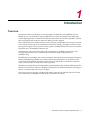
Overview ......................................................................................................................................................... 1-1
Features and Benefits .................................................................................................................................... 1-2
Applications .................................................................................................................................................... 1-2
Chapter 2: Network Configuration
Overview ......................................................................................................................................................... 2-1
Network Topologies ........................................................................................................................................ 2-2
Ad Hoc Wireless LAN (no Access Point or Bridge) .................................................................................. 2-2
Infrastructure Wireless LAN ..................................................................................................................... 2-3
Infrastructure Wireless LAN for Roaming Wireless PCs ..........................................................................2-4
Chapter 3: Initial Configuration
Overview ......................................................................................................................................................... 3-1
Initial Configuration Steps ............................................................................................................................... 3-1
Using the CLI ........................................................................................................................................... 3-2
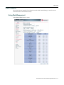
Using Web Management .......................................................................................................................... 3-4
Chapter 4: Advanced Configuration
Overview ......................................................................................................................................................... 4-1
Using the Web Interface ........................................................................................................................... 4-1
Using the Command Line Interface (CLI) ................................................................................................. 4-1
Identification ................................................................................................................................................... 4-3
Using Web Management .......................................................................................................................... 4-3
Using the CLI ........................................................................................................................................... 4-4
TCP / IP Settings ............................................................................................................................................ 4-5
Using Web Management .......................................................................................................................... 4-6
Using the CLI ........................................................................................................................................... 4-8
RADIUS .......................................................................................................................................................... 4-9
Using Web Management ........................................................................................................................ 4-10
Using the CLI ......................................................................................................................................... 4-11
PPPoE ..........................................................................................................................................................4-12
Using Web Management ........................................................................................................................ 4-12
Using the CLI ......................................................................................................................................... 4-13
Authentication ............................................................................................................................................... 4-14
Using Web Management ........................................................................................................................ 4-14
Using the CLI ......................................................................................................................................... 4-15
Filter Control ................................................................................................................................................. 4-17
Using Web Management ........................................................................................................................ 4-17
v
Using the CLI ......................................................................................................................................... 4-19
CLI Commands for VLAN Support ................................................................................................... 4-19
CLI Commands for Filtering.............................................................................................................. 4-21
QoS .............................................................................................................................................................. 4-22
Using Web Management ........................................................................................................................ 4-22
Using the CLI ......................................................................................................................................... 4-24
CDP Settings ................................................................................................................................................ 4-26
Using Web Management ........................................................................................................................ 4-26
Using the CLI ......................................................................................................................................... 4-27
Rogue AP Detection ..................................................................................................................................... 4-29
Using Web Management ........................................................................................................................ 4-30
Using the CLI ......................................................................................................................................... 4-31
SNMP ........................................................................................................................................................... 4-31
Using Web Management ........................................................................................................................ 4-32
Using the CLI ......................................................................................................................................... 4-36
Administration ............................................................................................................................................... 4-37
Changing the Password ......................................................................................................................... 4-37
Using Web Management .................................................................................................................. 4-37
Using the CLI.................................................................................................................................... 4-38
Enabling Disabling Com Port ................................................................................................................. 4-38
Using Web Management .................................................................................................................. 4-38
Using the CLI.................................................................................................................................... 4-38
Upgrading Firmware ............................................................................................................................... 4-39
Using Web Management .................................................................................................................. 4-40
Using the CLI.................................................................................................................................... 4-40
System Log ................................................................................................................................................... 4-42
Using Web Management ........................................................................................................................ 4-42
Using the CLI ......................................................................................................................................... 4-44
Configuring SNTP .................................................................................................................................. 4-45
Using the CLI to Configure SNTP .......................................................................................................... 4-46
Radio Interface ............................................................................................................................................. 4-47
Radio Signal Characteristics .................................................................................................................. 4-47
Virtual APs (VAPs) ................................................................................................................................. 4-47
Using the CLI for the 802.11a Interface .................................................................................................4-54
Using the CLI for 802.11b/g Interface .................................................................................................... 4-56
Using the CLI for the VAPs .................................................................................................................... 4-58
Security ......................................................................................................................................................... 4-60
Wired Equivalent Privacy (WEP) ............................................................................................................ 4-62
Using Web Management ........................................................................................................................ 4-62
CLI Commands for 802.1x Authentication ....................................................................................... 4-68
CLI Commands for Local MAC Authentication ................................................................................. 4-70
CLI Commands for RADIUS MAC Authentication ............................................................................ 4-72
CLI Commands for 802.1x Authentication ....................................................................................... 4-74
Using the CLI for WEP Shared Key Security ......................................................................................... 4-74
Using the CLI Commands for WEP over 802.1x Security ...................................................................... 4-76
Status Information ........................................................................................................................................ 4-77
Using Web Management to View AP Status .......................................................................................... 4-78
Using the CLI to Display AP Status ........................................................................................................ 4-80
Using Web Management to View CDP Status .......................................................................................4-81
Using the CLI to Display CDP Status ..................................................................................................... 4-81
Using Web Management to View Station Status ................................................................................... 4-82
Using the CLI to Display Station Status .................................................................................................4-84
Using Web Management to View Neighbor AP Detection Status .......................................................... 4-86
vi
Using the CLI to View Neighbor AP Detection Status ............................................................................4-88
Using Web Management to View Event Logs ........................................................................................ 4-90
Using the CLI to View Event Logs .......................................................................................................... 4-91
Appendix A: Using the Command Line Interface
Accessing the CLI .......................................................................................................................................... A-1
Console Connection ................................................................................................................................ A-1
Telnet Connection ................................................................................................................................... A-2
Entering Commands ...................................................................................................................................... A-3
Keywords and Arguments ....................................................................................................................... A-3
Minimum Abbreviation ............................................................................................................................. A-3
Command Completion ............................................................................................................................ A-3
Getting Help on Commands .......................................................................................................................... A-4
Showing Commands ............................................................................................................................... A-4
Partial Keyword Lookup .......................................................................................................................... A-4
Negating the Effect of Commands .......................................................................................................... A-5
Viewing Command History ...................................................................................................................... A-5
Understanding Command Modes .................................................................................................................. A-6
Exec Commands ..................................................................................................................................... A-6
Configuration Commands ....................................................................................................................... A-6
Command Line Processing ........................................................................................................................... A-8
Command Groups ......................................................................................................................................... A-9
General Commands .............................................................................................................................. A-10
configure .......................................................................................................................................... A-10
end................................................................................................................................................... A-11
exit ................................................................................................................................................... A-11
ping.................................................................................................................................................. A-12
reset................................................................................................................................................. A-13
show history..................................................................................................................................... A-14
show line.......................................................................................................................................... A-15
System Management Commands ......................................................................................................... A-16
country............................................................................................................................................. A-18
prompt ............................................................................................................................................. A-20
system contact................................................................................................................................. A-21
system location ................................................................................................................................ A-21
system name ................................................................................................................................... A-22
username......................................................................................................................................... A-22
password ......................................................................................................................................... A-23
com-port .......................................................................................................................................... A-23
ip http port........................................................................................................................................ A-24
ip http server.................................................................................................................................... A-25
ip https port...................................................................................................................................... A-26
ip https server .................................................................................................................................. A-27
ip ssh-server .................................................................................................................................... A-28
ip ssh-server port ............................................................................................................................. A-29
ip telnet-server................................................................................................................................. A-30
logging on ........................................................................................................................................ A-31
logging host ..................................................................................................................................... A-31
logging console................................................................................................................................ A-33
logging level..................................................................................................................................... A-34
logging facility-type .......................................................................................................................... A-35
show logging.................................................................................................................................... A-36
show events..................................................................................................................................... A-37
logging clear .................................................................................................................................... A-38
vii
sntp-server ip ................................................................................................................................... A-39
sntp-server enable........................................................................................................................... A-40
sntp-server date-time....................................................................................................................... A-41
sntp-server daylight-saving.............................................................................................................. A-42
sntp-server timezone ....................................................................................................................... A-43
show sntp ........................................................................................................................................ A-43
show system.................................................................................................................................... A-44
show version.................................................................................................................................... A-45
PPPoE Commands ............................................................................................................................... A-45
ip pppoe........................................................................................................................................... A-46
pppoe ip allocation mode................................................................................................................. A-47
pppoe ipcp dns ................................................................................................................................ A-48
pppoe lcp echo-interval ................................................................................................................... A-49
pppoe lcp echo-failure ..................................................................................................................... A-50
pppoe local ip .................................................................................................................................. A-51
pppoe remote ip............................................................................................................................... A-52
pppoe username.............................................................................................................................. A-53
pppoe password .............................................................................................................................. A-54
pppoe service-name ........................................................................................................................ A-55
pppoe restart ................................................................................................................................... A-55
show pppoe ..................................................................................................................................... A-56
SNMP Commands ................................................................................................................................ A-57
snmp-server community .................................................................................................................. A-58
snmp-server contact ........................................................................................................................ A-59
snmp-server enable server .............................................................................................................. A-60
snmp-server host ............................................................................................................................ A-61
snmp-server location ....................................................................................................................... A-62
show snmp ...................................................................................................................................... A-63
snmp-server trap ............................................................................................................................. A-64
snmp-server engine-id ..................................................................................................................... A-66
snmp-server user............................................................................................................................. A-67
snmp-server targets......................................................................................................................... A-69
snmp-server filter ............................................................................................................................. A-70
snmp-server filter-assignments ....................................................................................................... A-71
snmp-server group .......................................................................................................................... A-72
show snmp groups .......................................................................................................................... A-73
show snmp users............................................................................................................................. A-74
show snmp group-assignments....................................................................................................... A-74
show snmp target ............................................................................................................................ A-75
show snmp filter............................................................................................................................... A-75
show snmp filter-assignments ......................................................................................................... A-76
Flash/File Commands ........................................................................................................................... A-76
bootfile ............................................................................................................................................. A-77
copy ................................................................................................................................................ A-77
delete............................................................................................................................................... A-79
dir..................................................................................................................................................... A-80
RADIUS Client Commands ................................................................................................................... A-81
radius-server address ...................................................................................................................... A-82
radius-server key ............................................................................................................................. A-82
radius-server port ............................................................................................................................ A-83
radius-server port-accounting .......................................................................................................... A-84
radius-server retransmit................................................................................................................... A-84
radius-server timeout....................................................................................................................... A-85
radius-server timeout-interim ........................................................................................................... A-85
viii
radius-server secondary .................................................................................................................. A-86
show radius ..................................................................................................................................... A-87
802.1x Port Authentication Commands ................................................................................................. A-88
802.1x.............................................................................................................................................. A-89
802.1x broadcast-key-refresh-rate .................................................................................................. A-91
802.1x session-key-refresh-rate ...................................................................................................... A-92
802.1x session-timeout.................................................................................................................... A-93
802.1x supplicant............................................................................................................................. A-94
mac-access permission ................................................................................................................... A-95
mac-access entry ............................................................................................................................ A-96
mac-authentication server ............................................................................................................... A-97
mac-authentication session-timeout ................................................................................................ A-98
mac-authentication password.......................................................................................................... A-99
show authentication ....................................................................................................................... A-100
Filtering Commands ............................................................................................................................ A-101
filter ibss-relay ............................................................................................................................... A-102
filter wireless-ap-manage .............................................................................................................. A-103
filter ethernet-type enable .............................................................................................................. A-103
filter ethernet-type protocol............................................................................................................ A-104
show filters..................................................................................................................................... A-105
Interface Commands ........................................................................................................................... A-106
interface......................................................................................................................................... A-109
cdp authentication ......................................................................................................................... A-110
cdp auto-enable............................................................................................................................. A-111
cdp disable .................................................................................................................................... A-112
cdp enable ..................................................................................................................................... A-113
cdp hold-time ................................................................................................................................. A-114
cdp tx-frequency ............................................................................................................................ A-115
show cdp ....................................................................................................................................... A-116
dns................................................................................................................................................. A-118
ip address ...................................................................................................................................... A-119
ip dhcp ........................................................................................................................................... A-121
shutdown ....................................................................................................................................... A-122
show interface ethernet ................................................................................................................. A-123
description ..................................................................................................................................... A-124
secure-access ............................................................................................................................... A-125
speed............................................................................................................................................. A-126
channel .......................................................................................................................................... A-127
turbo .............................................................................................................................................. A-128
ssid ................................................................................................................................................ A-129
beacon-interval .............................................................................................................................. A-130
dtim-period..................................................................................................................................... A-131
fragmentation-length...................................................................................................................... A-132
preamble........................................................................................................................................ A-133
ibss relay ....................................................................................................................................... A-134
rts-threshold................................................................................................................................... A-135
authentication ................................................................................................................................ A-136
encryption ...................................................................................................................................... A-137
key ................................................................................................................................................. A-138
transmit-key ................................................................................................................................... A-139
transmit-power............................................................................................................................... A-140
max-association............................................................................................................................. A-141
multicast-data-rate......................................................................................................................... A-142
ix
multicast-cipher ............................................................................................................................. A-143
unicast-cipher ................................................................................................................................ A-144
wpa-clients..................................................................................................................................... A-145
wpa-mode...................................................................................................................................... A-147
wpa-preshared-key........................................................................................................................ A-148
vap................................................................................................................................................. A-149
shutdown ....................................................................................................................................... A-150
show interface wireless ................................................................................................................. A-151
show station................................................................................................................................... A-152
IAPP Commands ................................................................................................................................. A-153
iapp................................................................................................................................................ A-153
QoS Commands .................................................................................................................................. A-154
qos mode....................................................................................................................................... A-155
qos mac-addr................................................................................................................................. A-156
qos ether-type................................................................................................................................ A-156
svp ................................................................................................................................................. A-157
show svp........................................................................................................................................ A-157
Rogue AP Commands ........................................................................................................................ A-158
rogue-ap enable ............................................................................................................................ A-159
rogue-ap duration .......................................................................................................................... A-160
rogue-ap interduration ................................................................................................................... A-161
rogue-ap interval............................................................................................................................ A-162
rogue-ap [interface-a | interface-g] scan........................................................................................ A-163
rogue-ap radius ............................................................................................................................. A-164
rogue-ap scan................................................................................................................................ A-165
rogue-ap sortmode ........................................................................................................................ A-166
show rogue-ap............................................................................................................................... A-167
VLAN Commands ............................................................................................................................... A-170
management-vlan .......................................................................................................................... A-172
management-vlanid ....................................................................................................................... A-173
vlan ................................................................................................................................................ A-174
native-vlanid .................................................................................................................................. A-175
untagged-vlanid ............................................................................................................................. A-176
Appendix B: Default Settings
Appendix C: Troubleshooting
Troubleshooting Steps ................................................................................................................................... C-1
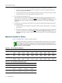
Maximum Distance Tables ............................................................................................................................ C-2
Index
x
Figures
2-1
2-2
2-3
Ad Hoc Wireless LAN ......................................................................................................................... 2-2
Infrastructure Wireless LAN................................................................................................................ 2-3
Infrastructure Wireless LAN for Roaming ........................................................................................... 2-4
Tables
4-1
4-2
4-3
4-4
4-5
4-6
4-7
A-1
A-2
A-3
A-4
A-5
A-6
A-7
A-8
A-9
A-10
A-11
A-12
A-13
A-14
A-15
A-16
A-17
A-18
A-19
C-1
C-2
C-3
Advanced Configuration ..................................................................................................................... 4-2
QoS Mode and Classifications ......................................................................................................... 4-23
SNMP Notifications ......................................................................................................................... 4-33
Logging Level Descriptions .............................................................................................................. 4-43
VLAN ID RADIUS Attributes ............................................................................................................. 4-50
Security Mechanisms ....................................................................................................................... 4-61
Status ............................................................................................................................................... 4-77
Command Class Modes .....................................................................................................................A-6
Command Line Processing Editing Keystrokes..................................................................................A-8
Command Groups ..............................................................................................................................A-9
General Commands .........................................................................................................................A-10
System Management Commands ....................................................................................................A-16
Country Codes..................................................................................................................................A-18
Alert Level Descriptions ....................................................................................................................A-34
PPPoE Commands...........................................................................................................................A-45
SNMP Commands............................................................................................................................A-57
SNMP Trap Messages ....................................................................................................................A-64
Flash/File Commands.......................................................................................................................A-76
RADIUS Client Commands ..............................................................................................................A-81
802.1x Access Control Commands ..................................................................................................A-88
Filtering Commands .......................................................................................................................A-101
Interface Commands (Ethernet and Wireless) ...............................................................................A-106
QoS Commands .............................................................................................................................A-154
Rogue AP Commands....................................................................................................................A-158
VLAN ID RADIUS Attributes ...........................................................................................................A-170
VLAN Commands...........................................................................................................................A-171
802.11a Wireless Distance .................................................................................................................C-2
802.11b Wireless Distance Table .......................................................................................................C-2
802.11g Wireless Distance Table .......................................................................................................C-3
xi
xii
Preface
Purpose of This Manual
This manual provides the configuration instructions for the RoamAbout Access Point 3000 using Web management and the Command Line Interface (CLI).
Intended Audience
This manual is intended for the wireless network manager who will configure the RoamAbout Access Point 3000. You should have a basic knowledge of Local Area Networks (LANs) and networking functions.
Associated Documents
You can download the documentation from the Enterasys Networks Web site. Documentation URL: http://www.enterasys.com/support/manuals
Documentacion URL: http://www.enterasys.com/support/manuals Dokumentation: http://www.enterasys.com/support/manuals
Document Conventions
The following icons are used in this document:
Caution: Contains information essential to avoid damage to the equipment.
Precaución: Contiene información esencial para prevenir dañar el equipo.
Achtung: Verweißt auf wichtige Informationen zum Schutz gegen Beschädigungen.
Note: Calls the reader’s attention to any item of information that may be of special importance.
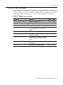
The following conventions are used in the text of this document:
Convention
Description
Bold font
Indicates mandatory keywords, parameters or keyboard keys.
italic font
Indicates complete document titles.
Courier font
Used for examples of information displayed on the screen.
Courier font in italics
Indicates a user-supplied value, either required or optional.
[]
Square brackets indicate an optional value.
{}
Braces indicate required values. One or more value may be required.
|
A vertical bar indicates a choice in values.
[x | y | z]
Square brackets with a vertical bar indicates a choice of a value.
RoamAbout Access Point 3000 Configuration Guide
xiii
Convention
Description
{x | y | z}
Braces with a vertical bar indicate a choice of a required value.
[x {y | z} ]
A combination of square brackets with braces and vertical bars indicates a
required choice of an optional value.
Getting Help
For additional support related to this device or document, contact Enterasys Networks using one of the following methods.
World Wide Web:
www.enterasys.com/support
Phone:
(603) 332-9400
1-800-872-8440 (toll-free in the U.S. and Canada)
For the Enterasys Networks Support toll-free number in your country:
www.enterasys.com/support/gtac-all.html
Email:
[email protected]
To expedite your message, please type [wireless] in the subject line.
To send comments or suggestions concerning this document to the Technical Writing Department:
[email protected]
To expedite your message, please type [techwriting] in the subject line, and include the document Part
Number in the email message.
Before calling Enterasys Networks, please have the following information ready:
xiv
Preface
•
Your Enterasys Networks service contract number •
A description of the failure
•
A description of any action(s) already taken to resolve the problem
•
The serial and revision numbers of all involved Enterasys Networks products in the network
•
A description of your network environment (layout, cable type, etc.)
•
Network load and frame size at the time of trouble (if known)
•
The device history (for example, have you returned the device before, is this a recurring problem, etc.)
•
Any previous Return Material Authorization (RMA) numbers
1
Introduction
Overview
The Enterasys Networks Wireless Access Point 3000 is an IEEE 802.11a/b/g (RBT3K‐AG and RBT3K‐AG‐G), or an IEEE 802.11b/g only (RBT3K‐1G), access point that provides transparent, wireless high‐speed data communications between the wired LAN and fixed, portable or mobile devices equipped with an 802.11a, 802.11b or 802.11g wireless adapter. This solution offers fast, reliable wireless connectivity with considerable cost savings over wired LANs (which include long‐term maintenance overhead for cabling). Using 802.11a, 802.11b, and 802.11g technology, this access point can easily replace a 10 Mbps Ethernet connection or seamless integration into a 10/100 Mbps Ethernet LAN.
In addition, the access point offers full network management capabilities through an easy to configure Web interface, and a command line interface for initial configuration and troubleshooting.
The IEEE 802.11a/g standard uses a radio modulation technique known as Orthogonal Frequency Division Multiplexing (OFDM), and a shared collision domain (CSMA/CA). It operates at the 5 GHz Unlicensed National Information Infrastructure (UNII) band for connections to 802.11a clients, and at 2.4 GHz for connections to 802.11g clients.
IEEE 802.11g includes backward compatibility with the IEEE 802.11b standard. IEEE 802.11b also operates at 2.4 GHz, but uses Direct Sequence Spread Spectrum (DSSS) modulation technology to achieve a communication rate of up to 11 Mbps. The access point also supports a 54 Mbps half‐duplex connection to Ethernet networks for each active channel (up to 108 Mbps in turbo mode on the 802.11a interface).
RoamAbout Access Point 3000 Configuration Guide
1-1
Features and Benefits
Features and Benefits
The features and benefits of the Access Point 3000 include the following:
•
Local network connection via 10/100 Mbps Ethernet ports or 54 Mbps wireless interface (supporting up to 250 mobile users per radio)
•
IEEE 802.11a, 802.11b, and 802.11g compliant •
Rogue AP Detection provides the ability to scan the airwaves and collect information about access points in the area. This feature detects neighboring access points and access points not authorized to participate in the network
•
Advanced security through 64‐bit (40‐bit), 128‐bit, 152‐bit Wired Equivalent Protection (WEP) encryption, IEEE 802.1x port authentication, Wi‐Fi Protected Access (WPA), AES (802.11i ready), SSID broadcast disable, remote authentication via RADIUS server, and MAC address filtering features to protect your sensitive data and authenticate only authorized users to your network
•
Provides seamless roaming within the IEEE 802.11a, 802.11b, and 802.11g WLAN environment
•
Automatically selects the available channel at power‐up
•
Allows you to configure up to seven Virtual Access Points (VAPs) on each radio interface each with its own set of authenticaion and security parameters
•
Supports Cabletron Discovery Protocol (CDP) •
Supports Spectralink Voice Priority (SVP)
Applications
The Wireless products offer a high speed, reliable, cost‐effective solution for 10/100 Mbps wireless Ethernet client access to the network in applications such as:
1-2
Introduction
•
Remote access to corporate network information
•
E‐mail, file transfer, and terminal emulation
•
Difficult‐to‐wire environments •
Historical or old buildings, asbestos installations, and open areas where wiring is difficult to employ
•
Frequently changing environments
•
Retailers, manufacturers, and banks that frequently rearrange the workplace or change location
•
Temporary LANs for special projects or peak times
•
Trade shows, exhibitions and construction sites which need temporary setup for a short time period
•
Retailers, airline and shipping companies that need additional workstations for a peak period
•
Auditors who require workgroups at customer sites
•
Access to databases for mobile workers, for example: doctors, nurses, retailers, or white‐collar workers who need access to databases while being mobile in a hospital, retail store, or an office campus
2
Network Configuration
Overview
The wireless solution supports a stand‐alone wireless network configuration as well as an integrated configuration with 10/100 Mbps Ethernet LANs.
Wireless network cards, adapters, and access points can be configured as:
•
Ad hoc for departmental, SOHO, or enterprise LANs
•
Infrastructure for wireless LANs
•
Infrastructure wireless LAN for roaming wireless PCs
The 802.11b and 802.11g frequency band which operates at 2.4 GHz can easily encounter interference from other 2.4 GHz devices, such as other 802.11b or g wireless devices, cordless phones and microwave ovens. If you experience poor wireless LAN performance, try the following measures: •
Limit any possible sources of radio interference within the service area
•
Increase the distance between neighboring access points to reduce interference
•
Decrease the signal strength of neighboring access points
•
Increase the channel separation of neighboring access points (e.g., up to 5 channels of separation for 802.11b, up to 4 channels for 802.11a, or 5 channels for 802.11g)
RoamAbout Access Point 3000 Configuration Guide
2-1
Network Topologies
Network Topologies
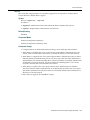
Ad Hoc Wireless LAN (no Access Point or Bridge)
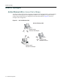
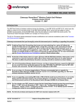
An ad hoc wireless LAN consists of a group of computers, each equipped with a wireless adapter, connected via radio signals as an independent wireless LAN. Computers in a specific ad hoc wireless LAN must therefore be configured to the same radio channel. Figure 2‐1 shows an example of this configuration.
Figure 2-1
Ad Hoc Wireless LAN
Ad Hoc Wireless LAN
Notebook with
Wireless USB Adapter
Notebook with
Wireless PC Card
Notebook with
Wireless PCI Adapter
2-2
Network Configuration
Network Topologies
Infrastructure Wireless LAN
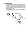
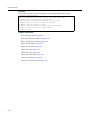
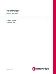
The access point also provides access to a wired LAN for wireless workstations. An integrated wired/wireless LAN is called an infrastructure configuration. A Basic Service Set (BSS) consists of a group of wireless PC users, and an access point that is directly connected to the wired LAN. Each wireless PC in this BSS can talk to any computer in its wireless group via a radio link, or access other computers or network resources in the wired LAN infrastructure via the access point.
The infrastructure configuration not only extends the accessibility of wireless PCs to the wired LAN, but also increases the effective wireless transmission range for wireless PCs by passing their signal through one or more access points.
A wireless infrastructure can be used for access to a central database, or for connection between mobile workers, as shown in Figure 2‐2.
Figure 2-2
Infrastructure Wireless LAN
Wired LAN Extension
to Wireless Adapters
File Server
Desktop PC
Switch
Notebook with Wireless
PC Card Adapter
DC 5V/3A
CONSO
LE
POE
IN
LOCK
Access Point
PC with Wireless
PCI Adapter
RoamAbout Access Point 3000 Configuration Guide
2-3
Network Topologies
Infrastructure Wireless LAN for Roaming Wireless PCs
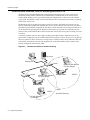
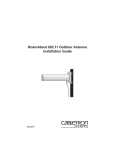
The Basic Service Set (BSS) defines the communications domain for each access point and its associated wireless clients. The BSS ID is a 48‐bit binary number based on the access point’s wireless MAC address, and is set automatically and transparently as clients associate with the access point. The BSS ID is used in frames sent between the access point and its clients to identify traffic in the service area. The BSS ID is only set by the access point, never by its clients. The clients only need to set the Service Set Identifier (SSID) that identifies the service set provided by one or more access points. The SSID can be manually configured by the clients, can be detected in an access point’s beacon, or can be obtained by querying for the identity of the nearest access point. For clients that do not need to roam, set the SSID for the wireless card to that used by the access point to which you want to connect.
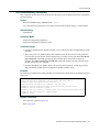
A wireless infrastructure can also support roaming for mobile workers. More than one access point can be configured to create an Extended Service Set (ESS), as shown in Figure 2‐3. By placing the access points so that a continuous coverage area is created, wireless users within this ESS can roam freely. All wireless network card adapters and Access Point 3000s, within a specific ESS, must be configured with the same SSID.
Figure 2-3
Infrastructure Wireless LAN for Roaming
File Server
Desktop PC
Switch
Notebook with Wireless
PC Card Adapter
DC 5V/3A
LE
CONSO
POE
IN
LOCK
Switch
Notebook with Wireless
PC Card Adapter
Access Point
DC 5V/3A
LE
CONSO
POE
IN
LOCK
Access Point
<BSS1>
PC with Wireless
PCI Adapter
2-4
Network Configuration
<ESS>
Seamless Roaming
<BSS2>
3
Initial Configuration
Overview
You can manage the RoamAbout Access Point 3000 with:
•
Command Line Interface (CLI) that you access through a direct connection to the console port
For a description of how to use the CLI, refer to Appendix A: Using the Command Line Interface. To view a list of all the CLI commands, refer to “Command Groups” on page A‐9.
•
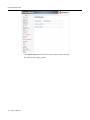
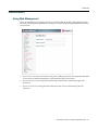
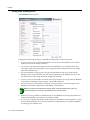
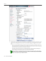
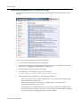
Web interface that you access through Internet Explorer or another Web browser
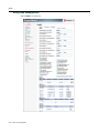
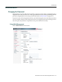
Note: You must click on the Apply button at the bottom of each Web interface page for the
configuration changes on that page to take effect.
•
An SNMP manager, such as Enterasys Networks NetSight management applications.
Refer to the RoamAbout Access Point 3000 Hardware Installation Guide for information on the physical setup of the access point.
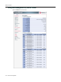
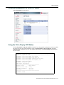
Initial Configuration Steps
You can perform the initial configuration steps through the CLI or the Web interface. The access point requests an IP address from a Dynamic Host Configuration Protocol (DHCP) server by default. If a DHCP server does not respond, then the access point uses the default address, 192.168.1.1. If you utilize a DHCP server to provision new elements in your IP network, use your DHCP server or other utilities to determine the IP address assigned to this access point. Then, use the DHCP assigned IP address to connect to the access point.
RoamAbout Access Point 3000 Configuration Guide
3-1
Initial Configuration Steps
Using the CLI
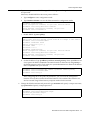
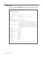
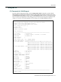
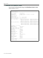
To use the CLI to minimally configure the access point, follow these steps:
1.
Make a serial connection to the access point’s console port as described in the RoamAbout Access Point 3000 Hardware Installation Guide.
2.
Use terminal emulation software to connect to the access point’s CLI.
3.
Enter admin for the user name, and password for the password to log in.
The access point 3000 CLI prompt appears.
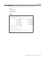
Username: admin
Password:********
RoamAbout 3000#
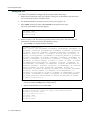
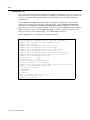
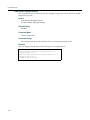
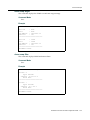
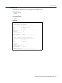
4.
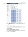
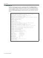
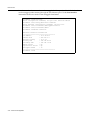
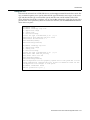
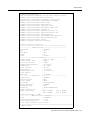
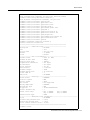
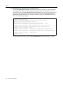
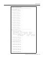
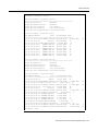
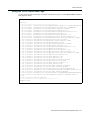
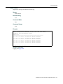
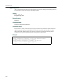
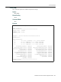
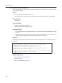
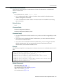
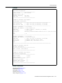
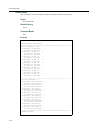
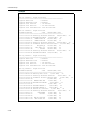
Set the Country Code. This restricts operation of the access point to the radio channels permitted for wireless networks in the specified country.
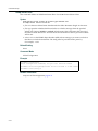
a.
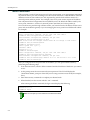
Type country ? to display the list of countries. RoamAbout 3000#country ?
WORD Country code: AL-ALBANIA, DZ-ALGERIA, AR-ARGENTINA, AM-ARMENIA, AUAUSTRALIA, AT-AUSTRIA, AZ-AZERBAIJAN, BH-BAHRAIN, BY-BELARUS, BE-BELGIUM,
BZ-BELIZE, BO-BOLVIA, BR-BRAZIL, BN-BRUNEI_DARUSSALAM, BG-BULGARIA, CACANADA, CL-CHILE, CN-CHINA, CO-COLOMBIA, CR-COSTA_RICA, HR-CROATIA, CYCYPRUS, CZ-CZECH_REPUBLIC, DK-DENMARK, DO-DOMINICAN_REPUBLIC, EC-ECUADOR,
EG-EGYPT, EE-ESTONIA, FI-FINLAND, FR-FRANCE, GE-GEORGIA, DE-GERMANY, GRGREECE, GT-GUATEMALA, HK-HONG_KONG, HU-HUNGARY, IS-ICELAND, IN-INDIA, IDINDONESIA, IR-IRAN,IE-IRELAND, IL-ISRAEL, IT-ITALY, JP-JAPAN, JO-JORDAN,
KZ-KAZAKHSTAN,KR-KOREA_REPUBLIC, KW-KUWAIT, LV-LATVIA, LB-LEBANON, LILIECHTENSTEIN, LT-LITHUANIA, LU-LUXEMBOURG, MO-MACAU, MK-MACEDONIA, MYMALAYSIA, MX-MEXICO, MC-MONACO, MA-MOROCCO, NL-NETHERLANDS, NZ- KP-NORTH
KOREA, NO-NORWAY, OM-OMAN, PK-PAKISTAN, PA-PANAMA, PE-PERU, PHPHILIPPINES, PL-POLAND, PT-PORTUGAL, PR-PUERTO_RICO, QA-QATAR, RO-ROMANIA,
RU-RUSSIA, SA-SAUDI_ARABIA, SG-SINGAPORE, SK-SLOVAK_REPUBLIC, SISLOVENIA, ZA-SOUTH_AFRICA, ES-SPAIN, SE-SWEDEN, CH-SWITZERLAND, SY-SYRIA,
TW-TAIWAN, TH-THAILAND, TR-TURKEY, UA-UKRAINE, AE-UNITED_ARAB_EMIRATES,
GB-UNITED_KINGDOM, US-UNITED_STATES, UY-URUGUAY, VE-VENEZUELA, VN-VIETNAM
RoamAbout 3000#country US
b.
Determine the code for your country, and then type country followed by your country code (for example, country US for United States).
c.
Reboot the RoamAbout Access Point 3000.
RoamAbout 3000#country US
Please reset the AP to make the country code change effective
RoamAbout 3000#reset board
Reboot system now? <y/n>: y
Username: admin
Password:********
RoamAbout 3000#
3-2
Initial Configuration
Initial Configuration Steps
5.
If your access point uses a DHCP assigned IP address go on to change the default username and password. Otherwise, disable DHCP for this access point as follows:
a.
Type configure to enter configuration mode.
b.
Type interface ethernet to access the Ethernet interface configuration mode.
RoamAbout 3000#configure
Enter configuration commands, one per line. End with CTRL/Z
RoamAbout 3000(config)#interface ethernet
Enter Ethernet configuration commands, one per line.
RoamAbout 3000(if-ethernet)#
c.
Disable DHCP. Type no ip dhcp.
RoamAbout 3000(if-ethernet)#no ip dhcp
DHCP client state has changed. Please reset AP for change to take effect.
RoamAbout 3000(if-ethernet)#exit
RoamAbout 3000#reset board
Reboot system now? <y/n>: y
Username: admin
Password:********
RoamAbout 3000#configure
Enter configuration commands, one per line. End with CTRL/Z
RoamAbout 3000(config)#interface ethernet
Enter Ethernet configuration commands, one per line.
RoamAbout 3000(if-ethernet)#
d. Set the IP Address. Type ip address ip‐address netmask gateway, where ip‐address is the access point’s IP address, netmask is the network mask for the network, and gateway is the default gateway router. Check with your system administrator to obtain an IP address that is compatible with your network.
RoamAbout 3000(if-ethernet)#ip address ip-address netmask gateway
RoamAbout 3000(if-ethernet)#end
RoamAbout 3000(config)#
After configuring the access point’s IP parameters, you can access the management interface from anywhere within the attached network. The command line interface can also be accessed using Telnet from any computer attached to the network. 6.
Change the default username and password: type username and specify a unique user name; type password and specify a unique password.
RoamAbout 3000(config)#username JadaPerl
RoamAbout 3000(config)#password G7nq1Z
Confirm new password: G7nq1Z
RoamAbout 3000(config)#
RoamAbout Access Point 3000 Configuration Guide
3-3
Initial Configuration Steps
7.
Enable Management VLAN.
a.
Type management‐vlanid and specify a management vlanid.
b.
Type management‐vlan enable, and reset the access point.
Note: Before enabling the VLAN feature on the access point, you must set up the network switch
port to support tagged VLAN packets from the access point. The switch port must also be
configured to accept the access point’s management VLAN ID and native VLAN IDs. Otherwise,
connectivity to the access point will be lost when you enable the VLAN feature.
RoamAbout 3000(config)#management-vlanid 10
RoamAbout 3000(config)#management-vlan enable
Reboot system now? <y/n>:y
Username: admin
Password:********
8.
Go to Chapter 4 for advanced configuration.
Using Web Management
To use the Web interface to minimally configure the access point, follow these steps:
1.
Open a Web browser and enter the access point’s IP address in the address field:
–
If your access point uses a DHCP assigned IP address, make sure the access point is connected to your network and enter the DHCP assigned IP address in your browser’s address field (use your DHCP server or other utility to determine the access point’s IP address).
–
If your access point uses a static IP address, connect a system to the access point’s Ethernet port and enter the default IP address: http://192.168.1.1/ in your browser’s address field.
The access point’s Login window appears.
2.
3-4
Initial Configuration
Enter the username admin and the password password and click LOGIN (for more information about the username and password, refer to Chapter 4).
Initial Configuration Steps
.
The Country Code page appears.
3.
To set the Country:
a.
Click the arrow in the Country pulldown menu to select the appropriate country, then click Apply at the bottom of the page.
The access point prompts you to reset.
b.
Click OK.
The Identification page appears.
RoamAbout Access Point 3000 Configuration Guide
3-5
Initial Configuration Steps
c.
Click Administration from the menu on the left‐hand side of the page.
The Administration page appears.
3-6
Initial Configuration
Initial Configuration Steps
d. Click Reset, at the bottom of the page.
The access point prompts you to confirm that you want to reboot the system.
e.
Click OK.
The access point reboots and the Login window appears.
f.
Enter the username admin and the password password and click LOGIN.
RoamAbout Access Point 3000 Configuration Guide
3-7
Initial Configuration Steps
4.
To set a static IP address:
a.
Click TCP/IP Settings from the menu on the left of the page.
The TCP/IP Settings page appears.
b.
Click the DHCP Client: Disable radio button.
An IP Address section appears on the page.
3-8
Initial Configuration
Initial Configuration Steps
c.
Specify IP address, Subnet Mask, Default Gateway, and Primary and Secondary DNS.
d. Click Apply at the bottom of the page.
e.
Type the IP address that you specified for the access point in your browser’s address field. For example, enter http://10.2.101.22/.
The Login window appears.
f.
Enter the username admin and the password password and click LOGIN.
g.
Click Administration from the menu on the left of the page.
The Administration page appears.
h. Click Reset, at the bottom of the page.
The access point prompts you to confirm that you want to reboot the system.
i.
Click OK.
The access point reboots and the Login window appears.
j.
Enter the username admin and the password password and click LOGIN .
RoamAbout Access Point 3000 Configuration Guide
3-9
Initial Configuration Steps
5.
Set username and password.
a.
Click Administration from the menu on the left of the page.
The Administration page appears.
b.
Specify a new username in the Username field.
c.
Specify a new password in the Password field.
d. Specify the new password again in the Confirm Password field.
e.
Click Apply at the bottom of the page.
The access point displays a Settings Saved message.
f.
Click OK.
The Administration page appears.
6.
Set management VLAN:
a.
Click Filter Control from the menu on the left of the page.
The Filter Control page appears.
3-10
Initial Configuration
Initial Configuration Steps
b.
Click the Management VLAN ID: field and enter the VLAN ID from which you will manage the AP.
c.
Click the Management VLAN: Enable radio button.
d. Click Apply at the bottom of the page.
The access point displays a dialog box indicating that the VLAN status has changed and will take effect after the next reboot. The dialog box prompts you to choose whether to reboot now or later.
e.
Click OK to reboot now.
The access point reboots and the Login window appears.
f.
7.
Enter the username and the password that you specified for this access point and click LOGIN.
Go to Chapter 4 for advanced configuration.
RoamAbout Access Point 3000 Configuration Guide
3-11
Initial Configuration Steps
3-12
Initial Configuration
4
Advanced Configuration
Overview
This chapter presents advanced configuration information organized according to the structure of the Web interface for easy reference.
Enterasys Networks recommends that you configure a user name and password to control management access to this device as the first advanced configuration step (refer to Administration on page 4‐37).
Table 4‐1 lists the configuration options and brief descriptions.
Using the Web Interface
You must click on the Apply button at the bottom of each Web interface page for the configuration changes on that page to take effect.
Using the Command Line Interface (CLI)
For a description of how to use the CLI, refer to Appendix A: Using the Command Line Interface. To view a list of all the CLI commands, refer to Command Groups on page A‐9.
RoamAbout Access Point 3000 Configuration Guide
4-1
Overview
Table 4-1
Advanced Configuration
Menu
Description
Page
Identification
Specifies the system name, location and contact.
4-3
TCP / IP Settings
Enables DHCP, or allows you to configures the IP address, subnet
mask, gateway, and domain name servers.
4-5
RADIUS
Configures the RADIUS server for wireless client authentication.
4-9
PPPoE Setup
Configures the access point to support Point-to-Point Protocol over
Ethernet (PPPoE) for WAN connection to an ISP.
4-12
Authentication
Configures the access point as an 802.1x authentication supplicant
with the network.
4-14
Filter Control
Filters communications between wireless clients, access to the
management interface from wireless clients, and traffic matching
specific Ethernet protocol types.
4-17
QoS
Allows you to select specific network traffic, prioritize it, and use
congestion-management and congestion-avoidance techniques to
provide preferential treatment.
4-22
CDP Settings
Configures AP to use Cabletron Discovery Protocol (CDP)
4-26
Rogue AP Detection
This feature scans the airwaves and collects information about
access points in the area.
4-29
SNMP
Controls access to this access point from management stations
using SNMP, as well as the hosts that will receive trap messages.
4-31
Administration
Configures user name and password for management access;
upgrades software from local file, FTP or TFTP server; resets
configuration settings to factory defaults; and resets the access
point.
4-37
System Log
Controls logging of error messages; sets the system clock via
SNTP server or manual configuration.
4-45
802.11a Interface
Configures the IEEE 802.11a interface.
4-47
Radio Settings
Configures radio signal parameters, and service set parameters for
the default interface and up to seven Virtual Access Points (VAPs).
4-47
Security
Configures 802.1x client authentication, with an option for MAC
address authentication, and data encryption with Wired Equivalent
Protection (WEP) or Wi-Fi Protected Access (WPA).
4-60
Configures the IEEE 802.11b/g interface.
4-47
Radio Settings
Configures radio signal parameters, and service set parameters for
the default interface and up to seven Virtual Access Points (VAPs).
4-47
Security
Configures 802.1x client authentication, with an option for MAC
address authentication, and data encryption with Wired Equivalent
Protection (WEP) or Wi-Fi Protected Access (WPA).
4-60
Displays AP status, CDP status, station status, Neighbor AP
Detection status, and event logs.
4-77
802.11b/g Interface
Status
4-2
Advanced Configuration
Identification
Identification
Using Web Management
The system information parameters for the Access Point 3000 can be left at their default settings. However, modifying these parameters can help you to more easily distinguish different devices in your network.
•
System Name is an alias used for the access point, enabling the device to be uniquely identified on the network. Default: RoamAbout AP; maximum length: 32 characters
•
System Location is a text string that describes the system location. Maximum length: 253 characters
•
System Contact is a text string that describes the system contact. Maximum length: 253 characters
RoamAbout Access Point 3000 Configuration Guide
4-3
Identification
Using the CLI
From the config mode, use the system name command to specify a new system name. Then return to the Exec mode, and use the show system command to display the changes to the system identification settings.
RoamAbout
RoamAbout
RoamAbout
RoamAbout
3000#configure
3000(config)#system name R&D
3000(config)#exit
3000#show system
System Information
====================================================================
Serial Number
: 034830992141
System Up time
: 0 days, 5 hours, 8 minutes, 42 seconds
System Name
: RoamAbout AP
System Location
:
System Contact
:
System Country Code : US - UNITED STATES
Ethernet MAC Address : 00-01-F4-61-9C-08
802.11a MAC Address : Default=00-01-F4-61-9C-36 VAP1=00-01-F4-36-3C-36
VAP2=00-01-F4-36-4C-36 VAP3=00-01-F4-36-5C-36
VAP4=00-01-F4-36-6C-36 VAP5=00-01-F4-36-7C-36
VAP6=00-01-F4-36-8C-36 VAP7=00-01-F4-36-9C-36
802.11b/g MAC Address : Default=00-0C-DB-81-3D-CD VAP1=00-0C-DB-81-3D-CE
VAP2=00-0C-DB-81-3D-CF VAP3=00-0C-DB-81-3D-D0
VAP4=00-0C-DB-81-3D-D1 VAP5=00-0C-DB-81-3D-D2
VAP6=00-0C-DB-81-3D-D3 VAP7=00-0C-DB-81-3D-D4
IP Address
: 10.2.43.203
Subnet Mask
: 255.255.0.0
Default Gateway
: 10.2.1.1
Management VLAN State : ENABLED
Management VLAN ID(AP : 3
IAPP State
: ENABLED
DHCP Client
: DISABLED
HTTP Server
: ENABLED
HTTP Server Port
: 80
HTTPS Server
: ENABLED
HTTPS Server Port
: 443
Slot Status
: Dual band(a/g)
SSH Server
: ENABLED
SSH Server Port
: 22
Telnet Server
: ENABLED
Com Port
: ENABLED
Software Version
: V3.1.0
====================================================================
RoamAbout 3000#
4-4
Advanced Configuration
TCP / IP Settings
TCP / IP Settings
Configuring the Access Point 3000 with an IP address expands your ability to manage the access point. A number of access point features depend on IP addressing to operate.
Note: You can use the Web browser interface to access the access point if the access point already
has an IP address that is reachable through your network.
By default, the Access Point 3000 will be automatically configured with IP settings from a Dynamic Host Configuration Protocol (DHCP) server. However, if you are not using a DHCP server to configure IP addressing, use the CLI to manually configure the initial IP values (refer to Chapter 3). After you have network access to the access point, you can use the Web browser interface to modify the IP configuration, if needed.
Note: If there is no DHCP server on your network, then the access point will automatically start up
with its default IP address, 192.168.1.1.
RoamAbout Access Point 3000 Configuration Guide
4-5
TCP / IP Settings
Using Web Management
Select TCP/IP Settings from the menu.
•
DHCP allows you to enable or disable the option to obtain the IP settings for the access point from a DHCP (Dynamic Host Configuration Protocol) server. The IP address, subnet mask, default gateway, and Domain Name Server (DNS) address are dynamically assigned to the access point by the network DHCP server. Default: Enable
Note: Enterasys Networks recommends that you reset the access point after changing the DHCP
client status.
•
4-6
IP Address
–
IP Address is the IP address of the access point. Valid IP addresses consist of four decimal numbers, 0 to 255, separated by periods. –
Subnet Mask is the mask that identifies the host address bits used for routing to specific subnets.
–
Default Gateway is the IP address of the router for the access point, which is used if the requested destination address is not on the local subnet.
–
Primary DNS and Secondary DNS are the IP addresses of the Domain Name Servers (DNS) on the network. A DNS maps numerical IP addresses to domain names and can be used to identify network hosts by familiar names instead of the IP addresses. Advanced Configuration
TCP / IP Settings
•
•
Web Servers –
HTTP Server allows the access point to be monitored or configured from a browser.
–
HTTP Port specifies the port to be used by the Web browser interface.
–
HTTPS Server allows you to enable or disable the secure HTTP server on the access point. –
HTTPS Port specifies the UDP port number used for HTTPS/SSL connection to the access pointʹs Web interface.
Telnet & SSH Settings Telnet allows you to manage the access point from anywhere in the network. Telnet is not secure from hostile attacks. Therefore, it is recommended to use the Secure Shell (SSH). The SSH protocol uses generated public keys to encrypt all data transfers passing between the access point and SSH‐enabled management station clients and ensures that data traveling over the network arrives unaltered.
–
Telnet Server disables or enables the Telnet server. Default: Enabled.
–
SSH Server disables or enables the SSH server. Default: Enabled.
–
SSH Port Number sets the UDP port for the SSH server. Range: 1‐22, 24‐79, 81‐442, 444‐
2312, 2314‐65535; Default: 22
Notes: SSH Port Number range may vary from range specified here; range varies based on default
ports defined on access point and port usage by other applications.
After software upgrade or configuration reset, the SSH server requires approximately five minutes
to generate host encryption keys. The SSH server is disabled while the keys are being generated.
RoamAbout Access Point 3000 Configuration Guide
4-7
TCP / IP Settings
Using the CLI
From the config mode, enter the interface configuration mode with the interface ethernet command. Use the ip dhcp command to enable the DHCP client, or no ip dhcp to disable it. To manually configure an address, specify the new IP address, subnet mask, and default gateway using the ip address command. To specify a DNS server address, use the dns server command. Then use the show interface ethernet command from the Exec mode to display the current IP settings.
RoamAbout 3000#configure
Enter configuration commands, one per line. End with CTRL/Z
RoamAbout 3000(config)#interface ethernet
Enter Ethernet configuration commands, one per line.
RoamAbout 3000(if-ethernet)#no ip dhcp
DHCP client state has changed. Please reset AP for change to take effect.
RoamAbout 3000(if-ethernet)#exit
RoamAbout 3000#reset board
Reboot system now? <y/n>: y
Username: admin
Password:********
RoamAbout 3000#configure
Enter configuration commands, one per line. End with CTRL/Z
RoamAbout 3000(config)#interface ethernet
Enter Ethernet configuration commands, one per line.
RoamAbout 3000(if-ethernet)#ip address 192.168.1.2 255.255.255.0
192.168.1.253
RoamAbout 3000(if-ethernet)#dns primary-server 192.168.1.55
RoamAbout 3000(if-ethernet)#dns secondary-server 10.1.0.55
RoamAbout 3000(if-ethernet)#end
RoamAbout 3000(config)#end
RoamAbout 3000#show interface ethernet
Ethernet Interface Information
========================================
IP Address
: 192.168.1.2
Subnet Mask
: 255.255.255.0
Default Gateway
: 192.168.1.253
Primary DNS
: 192.168.1.55
Secondary DNS
: 10.1.0.55
Admin status
: Up
Operational status : Up
Untagged VlanId
: 1
========================================
RoamAbout 3000#
4-8
Advanced Configuration
RADIUS
RADIUS
Remote Authentication Dial‐in User Service (RADIUS) is an authentication protocol that uses software running on a central server to control access to RADIUS‐aware devices on the network. An authentication server contains a database of user credentials for each user that requires access to the network.
A primary RADIUS server must be specified for the Access Point 3000 to implement IEEE 802.1x network access control and Wi‐Fi Protected Access (WPA) wireless security. A secondary RADIUS server may also be specified as a backup should the primary server fail or become inaccessible
If you are using MAC authentication, you must provide the following information to the RADIUS Server Network Administrator:
•
MAC Address of your wireless client. This becomes the username, which is case‐sensitive (lower‐case), and in the format: 00‐01‐f4‐ab‐cd‐ef.
•
Configure the RADIUS server to authenticate using the default password of “NOPASSWORD” for all the MAC address based user names.
Notes: This guide assumes that you already configured RADIUS server(s) to support the access
point. Configuration of RADIUS server software is beyond the scope of this guide, refer to the
documentation provided with the RADIUS server software.
If you are using RADIUS, it is highly recommended that you assign a static IP address to ensure that
the address doesn’t change via DHCP.
RoamAbout Access Point 3000 Configuration Guide
4-9
RADIUS
Using Web Management
Select RADIUS from the menu.
Configure the following settings to use RADIUS authentication on the access point:
•
IP Address/Server Name specifies the IP address or host name of the RADIUS server. The IP address must be an IP Version 4 address.
•
Port Number is the UDP port number used by the RADIUS server for authentication. This value must match the configuration of your primary RADIUS authentication server. Range: 1024‐65535; Default: 1812
•
Key is the shared text string used to encrypt messages between the access point and the RADIUS server. Be sure that the same text string is specified on the RADIUS server. Do not use blank spaces in the string. Maximum length: 255 characters
•
Timeout (seconds) is the number of seconds the access point waits for a reply from the RADIUS server before re‐sending a request. Range: 1‐60 seconds; Default: 5
•
Retransmit attempts is the number of times the access point tries to re‐send a request to the RADIUS server before authentication fails. Range: 1‐30; Default: 3
Note: For the Timeout and Retransmit attempts fields, accept the default values unless you
experience problems connecting to the RADIUS server over the network.
4-10
•
RADIUS Accounting enables or disables the AP to send RADIUS accounting information for clients to the RADIUS accounting server. Default: Disable
•
Accounting Port specifies the specific destination port for RADIUS accounting packets. A value between 1024 and 65535. This value must match the configuration of your primary RADIUS accounting server. Default: 1813
Advanced Configuration
RADIUS
•
Interim Update Timeout determines how often to send accounting updates from the access point to the server for this session. This value can be overridden by the RADIUS server. Default: 3600 seconds (one hour), Range: 60 seconds (one minute) to 86400 seconds (one day).
Secondary Radius Server Setup is used to configure a second RADIUS server to provide a backup in case the primary server fails. The access point uses the secondary server if the primary server fails or becomes inaccessible. Once the access point switches over to the secondary server, it periodically attempts to establish communication again with primary server. If communication with the primary server is re‐established, the secondary server reverts to a backup role.
Using the CLI
From the global configuration mode, use the radius‐server address command to specify the address of the primary RADIUS server, or the radius‐server secondary address command to specify the address of the secondary RADIUS server. (The following example configures settings for the primary RADIUS server.) Use the radius‐server or radius server secondary and key, port, port‐accounting, retransmit, timeout, and timeout‐iterim commands to configure the other RADIUS server parameters. Use the show radius command from the Exec mode to display the current settings for the primary and secondary RADIUS servers.
RoamAbout
RoamAbout
RoamAbout
RoamAbout
RoamAbout
RoamAbout
RoamAbout
RoamAbout
RoamAbout
RoamAbout
3000#configure
3000(config)#radius-server
3000(config)#radius-server
3000(config)#radius-server
3000(config)#radius-server
3000(config)#radius-server
3000(config)#radius-server
3000(config)#radius-server
3000(config)#exit
3000#show radius
address 192.168.1.25
port 181
key green
timeout 10
retransmit 5
port-accounting 1813
port-accounting enable
Radius Server Information
========================================
IP
: 192.168.1.25
Port
: 181
Key
: *****
Retransmit
: 5
Timeout
: 10
Accounting Port : 1813
InterimUpdate vv: 3600
========================================
Radius Secondary Server Information
========================================
IP
: 0.0.0.0
Port
: 1812
Key
: *****
Retransmit
: 3
Timeout
: 5
Accounting Port : 0
InterimUpdate vv: 3600
========================================
RoamAbout 3000#
RoamAbout Access Point 3000 Configuration Guide
4-11
PPPoE
PPPoE
Since many Internet Service Providers (ISP) use Point‐to‐Point Protocol over Ethernet (PPPoE) to establish communications with end users, the access point includes a built‐in client for this protocol. You can configure the access point to support PPPoE as an authentication method to establish communications with end users.
Using Web Management
Select PPPoE Settings from the menu.
4-12
•
PPPoE: enables the access point to support PPPoE as an authentication method to establish communications with end users through an ISP. Default: Disable
•
Username: The username assigned by your service provider for the PPPoE tunnel. The range is 1 to 63 alphanumeric characters.
•
Password: The password assigned by your service provider for the PPPoE tunnel. The range is 1 to 63 alphanumeric characters.
•
Service Name: The service name assigned by your service provider for the PPPoE. The service name may be required by some service providers. The range is 1 to 63 alphanumeric characters.
•
IP Allocation Mode: Specifies how IP addresses for the PPPoE tunnel are configured on the RJ‐
45 interface. The allocation mode depends on the type of service you have purchased from the ISP. If Automatically allocated is selected, DHCP is used to allocate the IP addresses for the PPPoE connection. If static addresses have been assigned to you by the ISP, you must manually enter the assigned addresses. The default setting is Automatically allocated.
Advanced Configuration
PPPoE
•
Local IP Address: The IP address of the local end of the PPPoE tunnel. If you selected Static assigned, you must enter the IP address.
•
Remote IP Address: The IP address of the remote end of the PPPoE tunnel. If you selected Static assigned, you must enter the IP address.
•
DNS Negotiation Mode: Allows you to enable or disable DNS. DNS servers are used to translate host computer names into IP addresses. PPPoE clients can request a primary and secondary DNS server from the network connection device at the remote end of the PPPoE tunnel. This request is passed to the remote end during the IP Control Protocol (IPCP) negotiation phase during session initialization.
•
Echo Interval: Sets the interval between sending echo requests for the PPPoE tunnel. Default 10.
•
Echo Failure: Echo requests are used to verify the integrity of the link through the PPPoE tunnel. Devices at either end of the link can issue an echo‐request. Devices receiving an echo‐
request must return an echo‐reply. If a link is busy with large data transfers, the echo‐reply may not be issued in a timely manner causing the link to timeout. If you experience this kind of problem, try extending the echo failure count or the echo interval. Default 3. Using the CLI
From the config mode, enter the interface ethernet command. Use the ip pppoe to enable PPPoE, or no ip pppoe to disable it. From the if‐ethernet mode, select from the following:
•
Use the pppoe ip allocation mode static command to use fixed addresses assigned by the ISP.
•
Use the pppoe ip allocation mode automatic command to use IP addresses that are dynamically assigned by the ISP.
•
Use the pppoe ipcp dns command to request allocation of IP addresses for Dynamic Naming System (DNS) servers from the device at the remote end of the PPPoE tunnel. Or, use the no
pppoe ipcp dns command.
•
Use the pppoe lcp echo-interval and pppoe lcp echo-failure commands to set the Link Control Protocol (LCP) echo request parameters for the PPPoE tunnel.
RoamAbout 3000#configure
Enter configuration commands, one per line. End with CTRL/Z
RoamAbout 3000(config)#interface ethernet
Enter Ethernet configuration commands, one per line.
RoamAbout 3000(if-ethernet)#ip pppoe
RoamAbout 3000(if-ethernet)#pppoe ip allocation mode static
RoamAbout 3000(if-ethernet)#pppoe ipcp dns
RoamAbout 3000(if-ethernet)#pppoe lcp echo-interval 30
RoamAbout 3000(if-ethernet)#pppoe local ip 10.7.1.200
RoamAbout 3000(if-ethernet)#
RoamAbout Access Point 3000 Configuration Guide
4-13
Authentication
Authentication
802.1x Supplicant allows you to enable the access point as an 802.1x authentication supplicant with the network.
Using Web Management
Select Authentication from the menu.
•
802.1x Supplicant allows you to enable or disable the access point as an 802.1x authentication supplicant to authenticate with the network.
If enabled, you must specify:
4-14
•
Username specifies the username that the access point uses to authenticate to the network. Range: 1 to 32 characters
•
Password specifies the password that the access point uses to authenticate to the network. Range: 1 to 32 characters
Advanced Configuration
Authentication
Using the CLI
Use the 802.1x supplicant user command from the global configuration mode to specify the username and password that the access points uses for authentication with the network. Use the 802.1x supplicant command to enable the access point as an 802.1x supplicant. To display the current settings, use the show authentication command from the Exec mode. Use the no 8021.x supplication command from the global configuration mode to disable.
RoamAbout Access Point 3000 Configuration Guide
4-15
Authentication
RoamAbout 3000#configure
Enter configuration commands, one per line. End with CTRL/Z
RoamAbout 3000(config)#802.1x supplicant user
User Name<1-32> : RBT3K-AND
Password<1-32> :password
Confirm password<1-32> :password
RoamAbout 3000(config)#802.1x supplicant
RoamAbout 3000(config)#
RoamAbout 3000(config)#exit
RoamAbout 3000#show authentication
802.11a Authentication Server Information
VAP AuthMode SessionTimeout Password
Default Local MAC
========================================================================
Default LOCAL
0 min
00000
ALLOWED
1
LOCAL
0 min
11111
ALLOWED
2
LOCAL
0 min
22222
ALLOWED
3
LOCAL
2 min
24567
ALLOWED
4
LOCAL
0 min
44444
ALLOWED
5
LOCAL
0 min
55555
ALLOWED
6
LOCAL
0 min
66666
ALLOWED
7
LOCAL
0 min
77777
ALLOWED
802.11b/g Authentication Server Information
VAP AuthMode SessionTimeout Password
Default Local MAC
========================================================================
Default LOCAL
0 min
NOPASSWORD
ALLOWED
1
LOCAL
0 min
NOPASSWORD
ALLOWED
2
LOCAL
0 min
NOPASSWORD
ALLOWED
3
LOCAL
0 min
NOPASSWORD
ALLOWED
4
LOCAL
0 min
NOPASSWORD
ALLOWED
5
LOCAL
0 min
NOPASSWORD
ALLOWED
6
LOCAL
0 min
NOPASSWORD
ALLOWED
7
LOCAL
0 min
NOPASSWORD
ALLOWED
802.1x Supplicant Information
========================================================================
802.1x supplicant
: DISABLED
802.1x supplicant user
: EMPTY
802.1x supplicant password
: EMPTY
MAC Address Filter Status List in SSID
802.11a 802.11b/g
Index MAC Address
Status
01234567 01234567
===== ================= ========= ======== ========
1 00-01-f4-88-b3-d7 ALLOWED ******** ********
2 00-00-11-22-33-44 ALLOWED *------- *------===================================================
RoamAbout 3000(config)#
4-16
Advanced Configuration
Filter Control
Filter Control
The access point can employ VLAN ID and network traffic frame filtering to control access to network resources and increase security. Using Web Management
Select Filter Control from the menu.
RoamAbout Access Point 3000 Configuration Guide
4-17
Filter Control
•
Management VLAN ID specifies the management VLAN ID for the access point.
The management VLAN is for managing the access point. For example, the access point allows traffic that is tagged with the specified VLAN to manage the access point via remote management, SSH, SNMP, Telnet, etc.
•
Management VLAN allows you to enable or disable management VLAN tagging support on the Access Point 3000. Default: Disable
•
Ethernet Untagged VLAN ID specifies the VLAN ID to which the AP maps untagged packets entering through the APʹs Ethernet port. Range: 1 to 4094
•
IAPP (Inter Access Point Protocol) enables the protocol signaling required for wireless clients to roam between different 802.11f‐compliant access points. Select Disable to disable 802.11f signaling. Default: Enable.
•
IBSS Relay Control, in conjunction with radio interface and Virtual AP (VAP) IBSS settings, controls whether clients associated with an interface or VAP can establish wireless communications with clients associated with other interfaces or VAPs. Default: All VAP mode
•
•
4-18
–
In All VAP Mode, clients associated with any IBSS enabled radio interfaces or VAPs can establish wireless communications with each other.
–
In Per VAP Mode, clients associated with a specific IBSS enabled radio interface or VAP can establish wireless communications with other clients associated with the same interface or VAP. For example, clients associated with VAP1 can establish wireless communications with each other but not with clients associated with an IBSS enabled VAP2.
Wireless AP Management controls management access to the Access Point 3000 from wireless clients. Management interfaces include the Web, Telnet, or SNMP. Default: Allow
–
Allow permits management access from wireless clients. The default setting.
–
Disallow blocks management access from wireless clients. Ethernet Type Filter controls checks on the Ethernet type of all incoming and outgoing Ethernet packets against the protocol filtering table. Default: Disable
–
Disable: The access point does not filter Ethernet protocol types.
–
Enable: The access point filters Ethernet protocol types based on the configuration of protocol types in the filter table. If a protocol has its status set to “ON,” in the filter table, the access point filters that protocol.
–
Local Management lists the Ethernet protocols.
–
ISO Designator specifies the ISO designators for each Ethernet protocol listed.
–
Status indicates, by radio button selection, whether the access point filters this Ethernet protocol. ON indicates filtering for this Ethernet protocol. Off indicates no filtering for this Ethernet protocol.
Advanced Configuration
Filter Control
Using the CLI
CLI Commands for VLAN Support
From the global configuration mode, use the management‐vlanid command to set the default Management VLAN ID for the Ethernet interface, then enable management VLAN tagging using the management‐vlan enable command (use no management‐vlan to disable). When you change the access point’s management VLAN setting, you must reboot the access point to implement the change. To view the current management VLAN settings, use the show system command.
RoamAbout 3000#configure
Enter configuration commands, one per line. End with CTRL/Z
RoamAbout 3000(config)#management-vlanid 3
RoamAbout 3000(config)#management-vlan enable
Reboot system now? <y/n>: y
Username: admin
Password:********
RoamAbout 3000#show system
System Information
====================================================================
Serial Number
: 034830992141
System Up time
: 0 days, 5 hours, 8 minutes, 42 seconds
System Name
: RoamAbout AP
System Location
:
System Contact
:
System Country Code : US - UNITED STATES
Ethernet MAC Address : 00-01-F4-61-9C-08
802.11a MAC Address : Default=00-01-F4-61-9C-36 VAP1=00-01-F4-36-3C-36
VAP2=00-01-F4-36-4C-36 VAP3=00-01-F4-36-5C-36
VAP4=00-01-F4-36-6C-36 VAP5=00-01-F4-36-7C-36
VAP6=00-01-F4-36-8C-36 VAP7=00-01-F4-36-9C-36
802.11b/g MAC Address : Default=00-0C-DB-81-3D-CD VAP1=00-0C-DB-81-3D-CE
VAP2=00-0C-DB-81-3D-CF VAP3=00-0C-DB-81-3D-D0
VAP4=00-0C-DB-81-3D-D1 VAP5=00-0C-DB-81-3D-D2
VAP6=00-0C-DB-81-3D-D3 VAP7=00-0C-DB-81-3D-D4
IP Address
: 10.2.43.203
Subnet Mask
: 255.255.0.0
Default Gateway
: 10.2.1.1
Management VLAN State : ENABLED
Management VLAN ID(AP : 3
IAPP State
: ENABLED
DHCP Client
: DISABLED
HTTP Server
: ENABLED
HTTP Server Port
: 80
HTTPS Server
: ENABLED
HTTPS Server Port
: 443
Slot Status
: Dual band(a/g)
SSH Server
: ENABLED
SSH Server Port
: 22
Telnet Server
: ENABLED
Com Port
: ENABLED
Software Version
: V3.1.0
====================================================================
RoamAbout 3000#
RoamAbout Access Point 3000 Configuration Guide
4-19
Filter Control
From the interface ethernet mode, use the untagged‐vlanid to specify a VLAN ID for the AP to use for untagged packets entering through the APʹs Ethernet port. Use the show interface command from the exec mode to view untagged‐vlanid status.
RoamAbout 3000#configure
Enter configuration commands, one per line. End with CTRL/Z
RoamAbout 3000(config)#interface ethernet
Enter Ethernet configuration commands, one per line.
RoamAbout 3000(if-ethernet)#untagged-vlanid 10
RoamAbout 3000(if-ethernet)#exit
RoamAbout 3000#show interface
Ethernet Interface Information
========================================
IP Address
: 10.2.43.203
Subnet Mask
: 255.255.0.0
Default Gateway
: 10.2.1.1
Primary DNS
: 134.141.93.21
Secondary DNS
: 134.141.79.92
Admin status
: Up
Operational status : Up
Untagged VlanId
: 10
========================================
RoamAbout 3000#
4-20
Advanced Configuration
Filter Control
CLI Commands for Filtering
Use the filter ibss‐relay command from the global configuration to set the mode for wireless‐to‐
wireless communications through the access point. Use the filter wireless‐ap‐manage command to restrict management access from wireless clients. Use the iapp or no iapp commands to enable or disable clients from roaming between access points. To configure Ethernet protocol filtering, use the filter ethernet‐type filter enable command to enable filtering and the filter ethernet‐type protocol <protocol> command to define the protocols that you want to filter. To remove a protocol filter from the table, use the no filter ethernet‐type protocol <protocol> command. To display the current settings, use the show filters command from the Exec mode.
RoamAbout 3000#configure
Enter configuration commands,
RoamAbout 3000(config)#filter
RoamAbout 3000(config)#filter
RoamAbout 3000(config)#filter
RoamAbout 3000(config)#exit
RoamAbout 3000#show filters
one per line. End with CTRL/Z
wireless-ap-manage
ethernet-type enable
ethernet-type protocol CDP
Protocol Filter Information
===========================================================
IBSS Relay Control
:All VAP Mode
802.11a VAP0 :ENABLED
802.11b/g VAP0 :ENABLED
VAP1 :ENABLED
VAP1 :ENABLED
VAP2 :ENABLED
VAP2 :ENABLED
VAP3 :ENABLED
VAP3 :ENABLED
VAP4 :ENABLED
VAP4 :ENABLED
VAP5 :ENABLED
VAP5 :ENABLED
VAP6 :ENABLED
VAP6 :ENABLED
VAP7 :ENABLED
VAP7 :ENABLED
Wireless AP Management :ENABLED
Ethernet Type Filter
:ENABLED
Enabled Protocol Filters
----------------------------------------------------------Protocol: CDP
ISO: 0x2000
===========================================================
RoamAbout 3000#
RoamAbout Access Point 3000 Configuration Guide
4-21
QoS
QoS
When you configure QoS (Quality of Service) on the access point, you can select specific network traffic, prioritize it, and use congestion‐management and congestion‐avoidance techniques to provide preferential treatment. Implementing QoS in your wireless LAN makes network performance more predictable and bandwidth utilization more effective.
The access point uses a weighted‐fair queuing scheme. Precedence is granted to the highest priority based on a weighted queuing scheme of all priorities, granting all priorities the ability to transmit/receive data.
Eight priority classes are defined. Network managers determine actual mappings. The highest priority is seven and the lowest priority is 0. For example, if you select 5 as the priority, 5 receives higher priority than those set with 0, 1, 2, 3, or 4 and lower priority than those set with 6 and 7 as their priority.
Using Web Management
Select QoS from the menu. The QoS Settings and Status page appears. The QoS mode selections are displayed in the following screen.
4-22
Advanced Configuration
QoS
•
QoS Mode drop‐down menu selections: –
Source Address allows you to specify priorities based on source MAC address. Specify source MAC addresses and associated priority levels in the MAC Address table.
–
Destination Address allows you to specify priorities based on destination MAC address. Specify destination MAC addresses and associated priority levels in the MAC Address table.
–
Ethernet Type allows you to specify priorities based on Ethernet types. Specify Ethernet types and associated priority levels in the Ethernet Type table. If you are using the CLI, the Ethernet type must be specified in the format HEX 0000‐FFFF (see the ISO Designator table listed in the Filter Control Web page).
–
802.1p is a specification that provides Layer 2 switches the ability to prioritize traffic (and perform dynamic multicast filtering). The prioritization specification works at the media access control (MAC) framing layer of the OSI model. To be compliant with 802.1p, Layer 2 switches must be capable of grouping incoming LAN packets into separate traffic classes.
Other than selecting 802.1p, and then clicking on Apply, there is no other user intervention on the access point. Priorities are set on the switch. •
SVP Status enables or disables the AP QoS to utilize Speculation Voice Priority (SVP) to give voice packets priority over data packets on the AP. Default: Disable
•
QoS Classifications are set in conjunction with the selected QoS mode. See Table 4‐2 for a list of QoS classifications associated with QoS modes.
Table 4-2
QoS Mode and Classifications
Mode
Classification
Source Address
MAC Address.
Specify priorities for up to 10 source addresses identified by MAC address.
Destination Address
MAC Address.
Specify priorities for up to 10 destination addresses identified by MAC address.
Ethernet Type
Ethernet Type.
Specify priorities for up to 10 Ethernet types specified by ISO designators. (See
Filter Control Web page for ISO designators.)
802.1p
N/A
RoamAbout Access Point 3000 Configuration Guide
4-23
QoS
Using the CLI
From the global configuration mode, use the qos mode command to set the type of classification (SA, DA, Ether‐Type, 802.1p‐Tag) that you want the access point to use. •
If you select source (SA) or destination (DA) address, you must use the qos mac‐address command to configure at least one MAC address for the qos mode to take affect. To display the QoS settings, use the show qos command from the Exec mode.
RoamAbout 3000#configure
Enter configuration commands, one per line. End with CTRL/Z
RoamAbout 3000(config)#qos mode SA
RoamAbout 3000(config)#qos mac-addr 00-01-f4-32-62-ac 6
RoamAbout 3000(config)#exit
RoamAbout 3000#
RoamAbout 3000#show qos
QoS information
======================================================
QoS Mode : Source Address
Address
Priority
-----------------------------------------------------00-01-F4-32-62-AC
6
=================================================================
====
RoamAbout 3000#
•
If you selected Ethernet Type, you must use the qos ether‐type command to configure at least one Ethernet type classification and the priority for the qos mode to take affect. To display the QoS settings, use the show qos command from the Exec mode.
RoamAbout 3000#configure
Enter configuration commands, one per line. End with CTRL/Z
RoamAbout 3000(config)#qos mode ether-type
RoamAbout 3000(config)#qos ether-type 0800 6
RoamAbout 3000(config)#
RoamAbout 3000(config)#exit
RoamAbout 3000#
RoamAbout 3000#show qos
QoS information
======================================================
QoS Mode : Ethernet Type
Ether_Type
Priority
-----------------------------------------------------0x0800
6
======================================================
RoamAbout 3000#
4-24
Advanced Configuration
QoS
To enable SVP, from the global configuration mode, use the svp command. To disable SVP, use the no version of the command. Use the show svp command from the Exec mode to view the SVP status.
RoamAbout 3000#configure
Enter configuration commands, one per line. End with CTRL/Z
RoamAbout 3000(config)#svp
RoamAbout 3000(config)#
RoamAbout 3000(config)#no svp
RoamAbout 3000(config)#exit
RoamAbout 3000#show svp
SVP:
Disabled
RoamAbout 3000#
RoamAbout Access Point 3000 Configuration Guide
4-25
CDP Settings
CDP Settings
Cabletron Discovery Protocol (CDP) settings controls how the AP uses CDP to discover neighbors on the physical LAN to which it connects. Using Web Management
Select CDP Settings from the menu. The CDP Settings page appears.
Note: The Port Status overrides the Global Status. Make the same selections for both global and
port status or make sure the port status settings match the behavior you want.
•
4-26
Global Status:
–
Disable ‐ disables this AP from using CDP. –
Enable ‐ enables this AP to use CDP and to send information about itself at the specified Transmit Frequency.
–
Auto ‐ enables this AP to use CDP and to send information about itself when it receives hello packets. Default: Auto •
Hold Time (15‐600): Specifies amount of time in seconds that the AP retains neighbor entry after receiving last hello packet. Default: 180 •
Transmit Frequency (5‐900): Interval in seconds between AP transmission of CDP hello packets. Default: 60 •
Authentication Key: Specifies a character string of up to16‐bytes to use as an authentication key for CDP packets.
Advanced Configuration
CDP Settings
•
Port Status: –
Disable ‐ disables this AP from using CDP. –
Enable ‐ enables this AP to use CDP and to send information about itself at the specified Transmit Frequency. –
Auto ‐ enables this AP to use CDP and to send information about itself only when neighbors request information. Default: Auto
Using the CLI
From the global configuration mode, enable cdp with the cdp auto‐enable or cdp enable commands. Specify the hold time, transmit frequency and optionally an authentication code using the cdp hold‐time, cdp tx‐frequency and cdp authentication commands. To disable cdp, use the cdp disable command. Use the show cdp command from Exec mode to display cdp settings, or to view neighbor entries or cdp traffic statics. RoamAbout Access Point 3000 Configuration Guide
4-27
CDP Settings
RoamAbout 3000#configure
Enter configuration commands, one per line. End with CTRL/Z
RoamAbout 3000(config)#cdp enable
RoamAbout 3000(config)#cdp hold-time 360
RoamAbout 3000(config)#cdp tx-frequency 120
RoamAbout 3000(config)#cdp authentication tC3Jc
RoamAbout 3000(config)#exit
RoamAbout 3000#show cdp
CDP Global Information
========================================
Global Status
: Enable
Authentication Code : tC3Jc
Transmit Frequency : 120 secs
Hold Time
: 360 secs
========================================
RoamAbout 3000#show cdp neighbor
CDP Neighbor Information
=================================================================
Last Change Time
: 7 days, 20 hours, 29 minutes, 26 seconds
Last Deletion Time
: 7 days, 20 hours, 28 minutes, 50 seconds
--------------------------------------------------------------------Neighbor IP Address : 10.2.191.52
Neighbor MAC Address : 00-E0-63-BB-93-C2
Time Mark
: 0 days, 0 hours, 0 minutes, 57 seconds
Device Type
: Dot1d Bridge
Description
: Enterasys Networks 6H303-48 Rev 05.05.01 03/14/03-11:10 ofc
Port
: 14
--------------------------------------------------------------------Neighbor IP Address : 10.2.43.200
Neighbor MAC Address : 00-01-F4-61-9B-F2
Time Mark
: 7 days, 20 hours, 29 minutes, 26 seconds
Device Type
: RoamAbout Wireless Access Point
Description
: RoamAbout AP ; SW version: V3.1.3
Port
: 1
=====================================================================
RoamAbout 3000#show cdp traffic
CDP Traffic Information
========================================
Input Packets
: 27283
Output Packets
: 16677
Invalid Version Packets : 0
Parse Error Packets
: 0
Transmit Error Packets : 0
Memory Error Packets
: 0
========================================
4-28
Advanced Configuration
Rogue AP Detection
Rogue AP Detection
This feature scans the airwaves and collects information about access points in the area.
It lists access points found during the scan on the Neighbor AP Detection Status page after the scan is complete.
If you enable the RADIUS authentication setting, this feature also identifies rogue APs. It performs a RADIUS server look up for the MAC address of each access point found. It reports access points whose MAC addresses it finds in the RADIUS server on the Neighbor AP Detection Status page. It reports access points whose MAC addresses it does not find as rogue APs in the syslog.
The term "rogue AP" is used to describe an access point that is not authorized to participate on the network.
It may not have the proper security settings in place. Rogue AP’s can potentially allow unauthorized users access to the network. In addition, a legitimate client may mistakenly associate to a rogue AP with invalid encryption settings and not to the AP that has been configured for it to use. This can cause a denial of service problem.
RoamAbout Access Point 3000 Configuration Guide
4-29
Rogue AP Detection
Using Web Management
Select Rogue AP Detection from the menu. The Rogue AP Detection selections are displayed in the following screen.
4-30
•
RADIUS Authentication enables the access point to discover rogue access points. Enabling RADIUS Authentication causes the access point to check the MAC address/Basic Service Set Identifier (BSSID) of each access point that it finds against a RADIUS server to determine whether the access point is allowed. With RADIUS authentication disabled, the access point can identify its neighboring access points only; it cannot identify whether the access points are allowed or are rogues. If you enable RADIUS authentication, you must configure a RADIUS server (on the RADIUS page) for this access point.
•
AP Scan Interval specifies the wait‐time between scans. Default: 720 minutes between scans.
•
AP Scan Duration specifies the amount of time to scan each frequency channel. Default: 350 milliseconds.
•
AP Scan Now button scans for the specified interface.
•
Scan All button scans for all 802.11a and 802.11b/g interfaces.
Advanced Configuration
SNMP
Using the CLI
Use the rogue‐ap command to detect neighboring access points and access points that are not authorized
to participate on the network. Use the interface‐a command to set access point detection parameters for 802.11a interfaces. Use the interface‐g command to set access point detection parameters for 802.11b/g interfaces. Set up the rogue AP feature by specifying the scan duration; interduration ‐
amount of time to make frequency channels active to clients; and the interval between scans. To use rogue AP detection, enable radius authentication using the radius command. To initiate a Rogue AP scan for all interfaces, use the scan command. Use the show rogue‐ap command from the Exec mode to view interface‐a and interface‐g settings and to view scan results for both interfaces.
RoamAbout 3000#configure
Enter configuration commands, one per line. End with CTRL/Z
RoamAbout 3000(config)#rogue-ap interface-a duration 500
RoamAbout 3000(config)#rogue-ap interface-a interduration
1000
RoamAbout 3000(config)#rogue-ap interface-a interval 750
RoamAbout 3000(config)#rogue-ap interface-a enable
RoamAbout 3000(config)#rogue-ap radius enable
RoamAbout 3000(config)#exit
SNMP
The access point includes an on‐board agent that supports SNMP versions 1, 2c, and 3. Access to the on‐board agent using SNMP v1 and v2c is controlled by community strings. To communicate with the access point, a management station must first submit a valid community string for authentication.
Access to the on‐board agent using SNMP v3 provides additional security features that cover message integrity, authentication, and encryption; as well as controlling notifications that are sent to specified user targets.
You can use a network management application such as Enterasys Networks NetSight Atlas Console to manage the Access Point 3000 via SNMP from a network management station.
To implement SNMP management, the Access Point 3000 must have an IP address and subnet mask, configured manually or dynamically. Once an IP address has been configured, appropriate SNMP communities and trap receivers should be configured.
RoamAbout Access Point 3000 Configuration Guide
4-31
SNMP
Using Web Management
Select SNMP from the menu.
4-32
Advanced Configuration
SNMP
•
SNMP allows you to enable or disable SNMP management access and also enables the access point to send SNMP traps (notifications). SNMP management is enabled by default.
•
Community Name (Read Only) defines the SNMP community access string that has read‐only access. Authorized management stations are only able to retrieve MIB objects. Default: public, maximum length: 23 characters, case sensitive
•
Community Name (Read/Write) defines the SNMP community access string that has read/write access. Authorized management stations are able to both retrieve and modify MIB objects. Default: private, maximum length: 23 characters, case sensitive
•
Trap Destination (1 to 4) enables or disables each of the four available trap destinations. If enabled, you must define the trap destination using the IP address and community name fields.
•
Trap Destination IP Address (1 to 4) specifies the recipient of SNMP notifications. Enter the IP address or the host name. Host Name: 1 to 20 characters
•
Trap Destination Community Name specifies the community string sent with the notification operation. Default: public, maximum length: 23 characters, case sensitive
•
Trap Configuration allows selection of specific SNMP notifications to send. Table 4‐3 lists the available notifications.
Table 4-3
SNMP Notifications
Notification
Description
sysSystemUp
The access point is up and running
sysSystemDown
The access point is about to shutdown and reboot
sysRadiusServerChanged
The access point was changed from the primary RADIUS
server to the secondary, or from the secondary to the primary
dot11StationAssociation
A client station successfully associated with the access point
dot11StationReAssociation
A client station successfully re-associated with the access point
dot11StationAuthentication
A client station was successfully authenticated
dot11StationRequestFail
A client station failed association, re-association, or
authentication
dot1xAuthFail
A 802.1x client station failed RADIUS authentication
dot1xMacAddrAuthSuccess
A client station successfully authenticated its MAC address with
the RADIUS server
dot11InterfaceAFail
The 802.11a interface failed
sntpServerFail
The access point failed to set the time from the configured
SNTP server
dot1xMacAddrAuthFail
A client station failed MAC address authentication with the
RADIUS server
dot1xAuthNotInitiated
A client station did not initiate 802.1x authentication
dot1xAuthSuccess
A 802.1x client station successfully authenticated by the
RADIUS server
localMacAddrAuthSuccess
A client station successfully authenticated its MAC address with
the local database on the access point
RoamAbout Access Point 3000 Configuration Guide
4-33
SNMP
Table 4-3
SNMP Notifications (continued)
localMacAddrAuthFail
A client station failed authentication with the local MAC address
database on the access point
pppLogonFail
The access point failed to log onto the PPPoE server using the
configured user name and password
iappStationRoamedFrom
A client station roamed from another access point (identified by
its IP address)
iappStationRoamedTo
A client station roamed to another access point (identified by its
IP address)
iappContextDataSent
A client station’s Context Data was sent to another access point
with which the station has associated
dot11InterfaceGFail
The 802.11g interface failed
•
•
Engine‐ID is used for SNMPv3 to identify the access point in a network of multiple access points. –
Entering the Engine‐ID invalidates all engine IDs that have been previously configured.
–
If the Engine‐ID is deleted or changed, all SNMP users will be cleared. You will need to reconfigure all users.
SNMP Users allows you configure the security requirement of users access.
Note: If you are going to use Group Lists, you must set up the Groups before adding the SNMP
users.
•
4-34
–
User specifies string to identify an SNMP user. (32 characters maximum)
–
Group is the name of the SNMP group to which the user is assigned (32 characters maximum). There are three pre‐defined groups: RO, RWAuth, or RWPriv.
–
Auth Type specifies the authentication type used for user authentication: “md5” or “none.”
–
Passphrase is the user password required when authentication, Auth Type, is used (8 to 32 characters).
–
Priv Type is the encryption type used for SNMP data encryption: “des” or “none.”
–
Passphrase is the user password required when data encryption, Priv Type, is used (8 to 32 characters).
–
Action: Add adds a new user; Edt allows you to edit an existing user; Del deletes the user.
Groups allow you to combine the users into groups of authorization and privileges. Users must be assigned to groups that have the same security levels. If a user who has “AuthPriv” security (uses authentication and encryption) is assigned to a read‐only (RO) group, the user will not be able to access the database. An AuthPriv user must be assigned to the RWPriv group with the AuthPriv security level.
Advanced Configuration
SNMP
•
•
•
Group List is the list of groups for SNMP v3 users. The access point enables SNMP v3 users to be assigned to three pre‐defined groups. Other groups cannot be defined. The available groups are:
–
RO is a read‐only group using no authentication and no data encryption. Users in this group use no security, authentication or encryption, in SNMP messages they send to the agent. This is the same as SNMP v1 or SNMP v2c.
–
RWAuth is a read/write group using authentication, but no data encryption. Users in this group send SNMP messages that use an MD5 key/password for authentication, but not a DES key/password for encryption.
–
RWPriv is a read/write group using authentication and data encryption. Users in this group send SNMP messages that use an MD5 key/password for authentication and a DES key/password for encryption. Both the MD5 and DES key/passwords must be defined.
–
Security Level
‐
noAuthNoPriv uses no authentication or privacy
‐
authNoPriv requires authentication, but not privacy ‐
authPriv requires authentication and privacy
–
WriteView allows write access to set objects.
–
Action Add adds a new group; Edt allows you to edit an existing group; Del deletes the group.
SNMP Targets
–
Target ID is the name you enter to identify the SNMP target. Maximum: 32 characters.
–
IP Address is the IP address of the user. –
UDP port is the UDP port of the server.
–
SNMP user is the name of the user. This name must match the name you entered in SNMP Users.
–
Filter ID is the filter ID that you entered in the SNMP Filter section.
–
Action Add adds a new target; Edt allows you to edit an existing target; Del deletes the target.
SNMP Filter
–
New Filter is the name you enter to identify a filter that includes or excludes certain notifications. Maximum: 32 characters.
–
Filter Type specifies whether the filter includes or excludes the specified notification. Includes means that notifications that are part of the subtree will be filtered out. Exclude means that notifications that are part of the subtree will be sent.
–
Subtree is an OID string that specifies the family of subtrees included or excluded by this filter. The string must be preceded with a period (.). For example, .1.3.6.1.
–
Action Add adds a filter; Edt allows you to edit an existing filter; Del deletes the filter.
RoamAbout Access Point 3000 Configuration Guide
4-35
SNMP
Using the CLI
The access point includes an on‐board agent that supports SNMP versions 1, 2c, and 3. Access to the on‐board agent using SNMP v1 and v2c is controlled by community strings. To communicate with the access point, a management station must first submit a valid community string for authentication.
Use the snmp‐server enable server command from the global configuration mode to enable SNMP. To set read/write and read‐only community names, use the snmp‐server community command. Use the snmp‐server location and snmp‐server contact commands to indicate the physical location of the access point and define a system contact. The snmp‐server host command defines trap receiver hosts. Use the snmp‐server trap command to specify the traps to send to hosts. To view the current SNMP settings, use the show snmp command.
Refer to Appendix A, for a complete list of SNMP commands.
RoamAbout 3000#configure
Enter configuration commands, one per line. End with CTRL/Z
RoamAbout 3000(config)#snmp-server community alpha rw
RoamAbout 3000(config)#
RoamAbout 3000(config)#snmp-server contact Steve
RoamAbout 3000(config)#snmp-server enable server
RoamAbout 3000(config)#snmp-server host 10.1.19.23 WWing
RoamAbout 3000(config)#snmp-server location WW-19
RoamAbout 3000(config)#snmp-server trap dot11StationAssociation
RoamAbout 3000(config)#snmp-server engine-id 1a:2b:3c:4d:00:ff
RoamAbout 3000(config)#snmp-server user
User Name<1-32> vvvvvv:dave
Group Name<1-32>
:RWPriv
md5 (Auth) Passphrase <8-32>:davepass1
des (Priv) Passphrase <8-32>:davepass2
RoamAbout 3000(config)#snmp-server targets mytraps 192.168.1.33 dave
RoamAbout 3000(config)#snmp-server group
Group Name<1-32> :RAPriv
1. NoAuthNoPriv
2. AuthNoPriv
3. AuthPriv
Select the security level<1,2,3>:[1]: 3
Write right<none,write>: none
RoamAbout 3000(config)#
4-36
Advanced Configuration
Administration
Administration
Changing the Password
Management access to the Web and CLI interface on the Access Point 3000 is controlled through a single user name and password. You can also gain additional access security by disabling the com port after configuring the AP, and using control filters (refer to Filter Control on page 4‐17.)
To protect access to the management interface, you should change the user name and password as soon as possible. If the user name and password are not configured, then anyone having access to the access point may be able to compromise access point and network security. Using Web Management
Select Administration from the menu.
RoamAbout Access Point 3000 Configuration Guide
4-37
Administration
•
•
Change Username/Password A username and password are required to configure the access point. Enterasys Networks strongly recommends that you change your password from the default value to ensure network security. –
Username is the name of the user. The default name is “admin”. Length: 3‐16 characters, case sensitive.
–
New Password is the password for management access. Length: 3‐16 characters, case sensitive.
–
Confirm New Password requires you to re‐enter the password for verification.
Reset Username/Password
Restore from default resets the username and/or the password back to the default settings. The default username is admin and the default password is password.
Using the CLI
Use the username and password commands from the CLI configuration mode.
RoamAbout
RoamAbout
RoamAbout
RoamAbout
RoamAbout
3000(config)#username John
3000(config)#password ****
3000(config)#confirm password ****
3000(config)#exit
3000#
Enabling Disabling Com Port
Using Web Management
Com Port Status radio buttons disable or enable the AP’s com port. Default: Enable
Using the CLI
Use the com‐port command from the Global Configuration mode.
RoamAbout
RoamAbout
RoamAbout
RoamAbout
4-38
Advanced Configuration
3000(config)#com-port disable
3000(config)#com-port enable
3000(config)#exit
3000#
Administration
Upgrading Firmware
You can upgrade the Access Point 3000 software from a local file on the management workstation, or from an FTP or TFTP server. New software may be provided periodically on the Wireless Web site (http://www.enterasys.com/products/wireless). After upgrading new software, you must reboot the Access Point 3000 to implement the new code. Until a reboot occurs, the Access Point 3000 will continue to run the software it was using before the upgrade started.
Before upgrading new software, verify that the Access Point 3000 is connected to the network and has been configured with a compatible IP address and subnet mask.
Bulk upgrades can be done using Enterasys Networks NetSight Inventory Manager. If you need to download from an FTP or TFTP server, perform the following additional tasks:
•
Obtain the IP address of the FTP or TFTP server where the access point software is stored.
•
Verify that the image is in the appropriate directory on the server.
•
If upgrading from an FTP server, be sure that you have an account configured on the server with a user name and password.
•
If VLANs are configured on the access point, determine the VLAN ID with which the FTP or TFTP server is associated, and then configure the management station, or the network port to which it is attached, with the same VLAN ID. If you are managing the access point from a wireless client, the VLAN ID for the wireless client must be configured on a RADIUS server.
RoamAbout Access Point 3000 Configuration Guide
4-39
Administration
Using Web Management
•
Current version displays the version number of code.
•
Local downloads an operation code image file from the Web management station to the access point using HTTP. Specify the name of the code file in the New firmware file field, either:
•
•
–
Use the Browse button to locate the image file locally on the management station.
–
Enter the name of the code file on the server. The new firmware file name should not contain slashes (\ or /), the leading letter of the file name should not be a period (.), and the maximum length for file names is 32 characters for files on the access point. (Valid characters: A‐Z, a‐z, 0‐9, “.”, “‐”, “_”).
–
Click Start Upgrade to download file.
Remote downloads an operation code image file from a specified remote FTP or TFTP server. –
Click the radio button beside FTP or TFTP server.
–
IP Address specifies the IP address or host name of FTP or TFTP server.
–
Username specifies the user ID for login on an FTP server.
–
Password specifies the password used for login on an FTP server.
–
Click Start Upgrade to download file.
Restore Factory Settings resets the configuration settings to the factory default settings (all configuration settings will be lost), and then you must reboot the system. Caution: If you restore factory defaults, all user configured information will be lost. You will have
to re-enter the default user name (admin) to regain management access to this device.
•
Reset Access Point reboots the system and retains your configuration settings. Note: If you have upgraded system software, then you must reboot the Access Point 3000 to
implement the new operation code.
4-40
Advanced Configuration
Administration
Using the CLI
To download software from a TFTP/FTP Server, use the copy command from the Exec mode. The copy command requires you to specify either the file type and then the server type, or the server type and then the file type. You must then specify the file name, and IP address of the TFTP server. When the download is complete, you can use the dir command to check that the new file is present in the access point file system. To run the new software, use the reset board command to reboot the access point.
RoamAbout 3000#
RoamAbout 3000#copy tftp file
1. Application image
2. Config file
3. Boot block image
Select the type of download<1,2,3>: [1]:1
TFTP Source file name:ets-img_v2.1.2.bin
TFTP Server IP:196.192.18.1
FTP Username:[admin]:
FTP Password:[password]:
RoamAbout 3000#copy ftp file
1. Application image
2. Config file
3. Boot block image
Select the type of download<1,2,3>: [1]:2
FTP Source file name:ets_310.cfg
FTP Server IP:10.2.20.140
FTP Username:[admin]:
FTP Password:[password]:
The configuration file was properly copied over to the system but a later
setup command will override the file. A reset is needed in order for the
configuration file changes to take place.
RoamAbout 3000#reset board
Reboot system now? <y/n>: y
RoamAbout Access Point 3000 Configuration Guide
4-41
System Log
System Log
The Access Point 3000 can be configured to send event and error messages to a System Log Server. The system clock can also be synchronized with a time server, so that all the messages sent to the Syslog server are stamped with the correct time and date.
The Access Point 3000 supports a logging process that can control error messages saved to memory or sent to a Syslog server. The logged messages serve as a valuable tool for isolating access point and network problems.
Using Web Management
Select System Log from the menu.
4-42
•
System Log Setup enables the logging of error messages.
•
Server (1, 2, 3, 4) enables the sending of log messages to a Syslog server host.
–
Server Name/IP is the IP address or name of a Syslog server.
–
Server UDP Port specifies the UDP port to use on that server.
•
Logging Console enables the logging of error messages to the console.
•
Logging Level sets the severity level for event logging.
Advanced Configuration
System Log
•
Logging Facility‐Type specifies the syslog facility to use for messages, (16 to 23) local 0 to local 7.
•
LoggingClear button clears the event log.
The system allows you to limit the messages that are logged by specifying a minimum severity level. Table 4‐4 lists the error message levels from the most severe (Alert) to least severe (Debug). The message levels that are logged include the specified minimum level up to the Alert level.
Table 4-4
Logging Level Descriptions
Error Level
Description
Emergency
Immediate action needed
Alerts
Immediate action needed
Critical
Critical conditions (e.g., memory allocation, or free memory error - resource exhausted)
Error
Error conditions (e.g., invalid input, default used)
Warning
Warning conditions (e.g., return false, unexpected return)
Notice
Normal but significant condition, such as cold start
Informational
Informational messages only
Debug
Debugging messages
Note: The access point error log can be viewed using the Event Logs window in the Status section
(refer to “Using Web Management to View Event Logs” on page 4-90).The Event Logs window
displays the last 128 messages logged in chronological order, from the newest to the oldest. Log
messages are erased when the device is rebooted.
RoamAbout Access Point 3000 Configuration Guide
4-43
System Log
Using the CLI
To enable logging on the access point, use the logging on command from the global configuration mode. The logging level command sets the minimum level of message to log. Use the logging console command to enable logging to the console. Use the logging host command to specify the Syslog servers. The logging facility‐type command sets the facility‐type associated with these messages. To view the current logging settings, use the show logging command from the Exec mode.
RoamAbout 3000#configure
Enter configuration commands, one per line. End with CTRL/Z
RoamAbout 3000(config)#logging on
RoamAbout 3000(config)#logging level alert
RoamAbout 3000(config)#logging console
RoamAbout 3000(config)#logging host 1 10.1.0.3 1024
RoamAbout 3000(config)#logging facility-type 19
RoamAbout 3000(config)#exit
RoamAbout 3000#show logging
Logging Information
============================================
Syslog State
: Enabled
Logging Console State
: Enabled
Logging Level
: Alert
Logging Facility Type
: 19
Servers
1: 10.1.0.3, UDP Port: 1024, State: Enabled
2: 0.0.0.0, UDP Port: 514, State: Disabled
3: 0.0.0.0, UDP Port: 514, State: Disabled
4: 0.0.0.0, UDP Port: 514, State: Disabled
=============================================
RoamAbout 3000#
4-44
Advanced Configuration
System Log
Configuring SNTP
Simple Network Time Protocol (SNTP) allows the Access Point 3000 to set its internal clock based on periodic updates from a time server. Maintaining an accurate time on the access point enables the system log to record meaningful dates and times for event entries.
The Access Point 3000 acts as an SNTP client, periodically sending time synchronization requests to specific time servers. You can configure up to two time server IP addresses. The access point will attempt to poll each server in the configured sequence.
•
SNTP Server configures the access point to operate as an SNTP client. When enabled, at least one time server IP address must be specified. When disabled, you manually set the date and time of the system clock.
–
Primary Server is the IP address of an SNTP time server that the access point attempts to poll for a time update. Default: 137.92.140.80
–
Secondary Server is the IP address of a secondary SNTP time server. The access point first attempts to update the time from the primary server; if this fails it attempts an update from the secondary server. Default: 192.43.244.18
Note: If SNTP is disabled, you can manually set the date and time of the system clock.
–
•
Set Time (SNTP Server disabled) allows you to manually set the current date and time for the location of this access point.
Set Time Zone. SNTP uses Coordinated Universal Time (or UTC, formerly Greenwich Mean Time, or GMT) based on the time at the Earth’s prime meridian, zero degrees longitude.
–
Enter Time Zone sets a time corresponding to your local time. You must indicate the number of hours your time zone is located before (East) or after (West) UTC.
–
Enable Daylight Saving provides a way to automatically adjust the system clock for Daylight Savings Time changes. To use this feature you must define the month and date to begin and to end the change from standard time. During this period the system clock is set back by one hour.
RoamAbout Access Point 3000 Configuration Guide
4-45
System Log
Using the CLI to Configure SNTP
To enable SNTP support on the access point, from the global configuration mode specify SNTP server IP addresses using the sntp‐server ip command, then use the sntp‐server enable command to enable the service. Use the sntp‐server timezone command to set the time zone for your location, and the sntp‐server daylight‐saving command to set daylight savings. To view the current SNTP settings, use the show sntp command from the Exec mode.
RoamAbout 3000#configure
Enter configuration commands, one per line. End with CTRL/Z
RoamAbout 3000(config)#sntp-server ip 1 10.1.0.19
RoamAbout 3000(config)#sntp-server enable
RoamAbout 3000(config)#sntp-server timezone +8
RoamAbout 3000(config)#sntp-server daylight-saving
Enter Daylight saving from which month<1-12>: 3
and which day<1-31>: 31
Enter Daylight saving end to which month<1-12>: 10
and which day<1-31>: 31
RoamAbout 3000(config)#exit
RoamAbout 3000#show sntp
SNTP Information
=========================================================
Service State
: Enabled
SNTP (server 1) IP: 10.1.0.19
SNTP (server 2) IP: 192.43.244.18
Current Time
: 19 : 35, Oct 10th, 2003
Time Zone
: +8 (TAIPEI, BEIJING)
Daylight Saving : Enabled, from Mar, 31th to Oct, 31th
=========================================================
RoamAbout 3000#
The following example shows how to manually set the system time when SNTP server support is disabled on the access point.
RoamAbout 3000#configure
Enter configuration commands, one per line. End with CTRL/Z
RoamAbout 3000(config)#no sntp-server enable
RoamAbout 3000(config)#sntp-server date-time
Enter Year<1970-2100>: 2003
Enter Month<1-12>: 10
Enter Day<1-31>: 10
Enter Hour<0-23>: 18
Enter Min<0-59>: 35
RoamAbout 3000(config)#exit
RoamAbout 3000#
4-46
Advanced Configuration
Radio Interface
Radio Interface
The IEEE 802.11a and 802.11b/g interfaces include configuration options for radio signal characteristics, Virtual APs (VAPs), and wireless security features. The configuration options for both radio interfaces are nearly identical, and are both covered in this section of the manual.
The Radio Settings section includes options for the radio characteristics of the interface, and the network definition of the default radio interface and up to seven VAPs per radio interface.
Radio Signal Characteristics
The access point can operate in several different radio modes, IEEE 802.11a only, 802.11b only, 802.11g only, 802.11b/g only, or a mixed 802.11a/b/g mode. Also note that 802.11g is backward compatible with 802.11b.
Note: The radio channel settings for the Access Point 3000 are limited by local regulations, which
determine the number of channels that are available.
The IEEE 802.11a interface operates within the 5 GHz band, at up to 54 Mbps in normal mode or up to 108 Mbps in Turbo mode.
You define network information and radio signal characteristics for the radio interface. The network information applies only to the Service Set Identifier (SSID) specified for the default radio interface. You specify unique network information for the SSID of each VAP you define for this radio interface (in addition to the default radio interface), if any.
Virtual APs (VAPs)
In addition to defining network characteristics for the default radio interface, you can define network characteristics for up to seven VAPs per radio interface. Each default radio interface and VAP has its own unique Service Set Identifier (SSID) with which clients can associate, using a variety of security and authentication options.
RoamAbout Access Point 3000 Configuration Guide
4-47
Radio Interface
Using Web Management
Select Radio Settings under the type of interface (802.11a or 802.11b/g) that you want to configure. 4-48
Advanced Configuration
Radio Interface
•
Interface Status disables/enables use of this default radio interface. Default: Enable.
Notes: Before enabling the radio card, you must set the country selection using the CLI. For more
information, see the RoamAbout Access Point 3000 Hardware Installation and Configuration Guide.
You must enable the default radio interface in order to configure VAPs on this radio interface.
•
Description is the description you provide to identify this default radio interface.
•
Network Name (SSID) is the name that you specify for the basic service set provided by the default radio interface. All clients that want to connect to the wired LAN through the default radio interface must set their SSIDs to this SSID.
•
Native VLAN ID is the VLAN ID for this default radio interface. The access point assigns this VLAN ID to all client traffic using this radio interface unless you assign unique VLAN IDs to clients through the RADIUS server using RFC 3580 (Section 3.31) tunnel attributes.
Using RFC 3580 (Section 3.31) tunnel attributes, you must configure user VLAN IDs (1‐4095) on the RADIUS server for each client authorized to access the network. The RADIUS server then assigns a VLAN ID to a client after successful authentication using IEEE 802.1x and a central RADIUS server. If a client does not have a configured VLAN ID, the access point assigns the client to the native VLAN ID for the radio interface.
When setting up VLAN IDs for each user on the RADIUS server, be sure to use the RADIUS attributes and values as indicated in Table 4‐5.
RoamAbout Access Point 3000 Configuration Guide
4-49
Radio Interface
Table 4-5
VLAN ID RADIUS Attributes
Number
RADIUS Attribute
Value
64
Tunnel-Type
VLAN (13)
65
Tunnel-Medium-Type
802
81
Tunnel-Private-Group-ID
VLANID (1 to 4095 in hexadecimal)
Note: The specific configuration of RADIUS server software is beyond the scope of this guide.
Refer to the documentation provided with the RADIUS server software.
•
•
Secure Access specifies whether clients can access the default radio interface network by discovering and automatically configuring the SSID, or whether clients must be already configured with the SSID. Default: Disable
–
Enabled, this default radio interface denies access to wireless clients that do not have the default radio interface network name (SSID) already configured. This default radio interface does not broadcast its network name, so that clients with operating systems like Windows XP do not see the name show up in wireless LAN configuration dialogs. –
Disabled, this default radio interface broadcasts its network name, and clients can discover and use the SSID to access this default radio interface’s wireless network. IBSS Relay: In conjunction with IBSS Relay Control settings (see Filter Control on page 4‐17), controls whether clients associated with the default radio interface can establish wireless communications with each other through the AP. Default: Disable
If you enable IBSS Relay, clients can establish wireless communications with each other through the AP. If you set the IBSS Relay Control to All VAP, then clients associated with all IBSS enabled radio interfaces or VAPs can establish wireless communications with each other. If you set the IBSS Relay Control to Per VAP, only the clients associated with the same (IBSS enabled) radio interface or VAP can communicate with each other. •
Maximum Associations (0‐255): Specifies the number of clients allowed to associate with this radio interface. •
Turbo Mode. (802.11a ONLY.) The normal 802.11a wireless operation mode provides connections up to 54 Mbps. Turbo Mode is an enhanced mode (not regulated in IEEE 802.11a) that provides a higher data rate of up to 108 Mbps. Enabling Turbo Mode allows the Access Point 3000 to provide connections up to 108 Mbps. Default: Disabled
Note: In normal mode, the access point provides a channel bandwidth of 20 MHz, and supports the
maximum number of channels permitted by local regulations (e.g., 13 channels for the United
States). In Turbo Mode, the channel bandwidth is increased to 40 MHz to support the increased data
rate. However, this reduces the number of channels supported (e.g., 5 channels for the United
States).
4-50
Advanced Configuration
Radio Interface
•
VLAN enables or disables VLAN tagging support on this default radio interface. If enabled, the access point will tag traffic passing from wireless clients to the wired network with the VLAN ID associated with each client on the RADIUS server. Up to 64 VLAN IDs can be mapped to specific wireless clients, allowing users to remain within the same VLAN as they move around a campus site. This feature can also be used to control access to network resources from wireless clients, thereby improving security. Default: Disable
–
Enable: When VLAN filtering is enabled, the access point must also have 802.1x authentication enabled and a RADIUS server configured. Wireless clients must also support 802.1x client software to be assigned to a specific VLAN. –
Disable: When VLAN filtering is disabled, this default radio interface ignores the VLAN tags on any received frames.
Note: If the radio interface has VLANs enabled, then VLANs are enabled on all VAPs associated
with this radio interface.
•
Radio Channel specifies the channel number for the operating radio channel in the access point. –
The 802.11a radio channel that the access point uses to communicate with wireless clients. When multiple access points are deployed in the same area, set the channel on neighboring access points at least four channels apart to avoid interference with each other. –
The 802.11b/g radio channel that the access point uses to communicate with wireless clients. When multiple access points are deployed in the same area, set the channel on neighboring access points at least five channels apart to avoid interference with each other. For example, in the United States you can deploy up to three access points in the same area (e.g., channels 1, 6, 11). Also note that the channel for wireless clients is automatically set to the same as that used by the access point to which it is linked. Range: 1‐11; Default: 6
•
Auto Channel Select enables the access point to automatically select an unoccupied radio channel. Default: Enabled
•
Working Mode (802.11b/g ONLY). The access point can be configured to support both 802.11b and 802.11g clients simultaneously, 802.11b clients only, or 802.11g clients only. Default: 802.11b and 802.11g
•
Transmit Power adjusts the power of the radio signals transmitted from the access point. The higher the transmission power, the farther the transmission range. Power selection is not just a trade off between coverage area and maximum supported clients. You also have to ensure that high‐power signals do not interfere with the operation of other radio devices in the service area. (Options: 100%, 50%, 25%, 12.5%, minimum.) Default: 100%
•
Maximum Tx Data Rate identifies the highest desired transmission speed for the broadcast traffic as forwarded by the AP to the wireless LAN.
–
802.11a defines 6, 9, 12, 18, 24, 36, 48, 54 Mbps data rates in the 5 GHz band. –
802.11b only defines: 1, 2, 5.5, 11 Mbps data rates in the 2.4 GHz band.
–
802.11g only, or 802.11b and 802.11g defines: 1, 2, 5.5, 6, 9, 11, 12, 18, 24, 36, 48, 54 Mbps data rates.
RoamAbout Access Point 3000 Configuration Guide
4-51
Radio Interface
•
Multicast Data Rate sets the speed to support for multicast traffic.
The faster the transmit speed, the shorter the coverage area at that speed. For example, an AP with an 802.11b 11 Mbit/s Radio Card can communicate with clients up to a distance of 375 feet in a semi‐open environment. However, only clients within the first 165 feet can communicate at 11 Mbit/s. Clients between 165 and 230 feet communicate at 5.5 Mbit/s. Clients between 230 and 300 feet communicate at 2 Mbit/s; and clients between 300 to 375 feet communicate at 1 Mbit/s.
•
Beacon Interval (20‐1000) sets the rate at which beacon signals are transmitted from the access point. The beacon signals allow wireless clients to maintain contact with the access point. They may also carry power‐management information. Default: 100 Ms
•
Data Beacon Rate (1‐255) sets the rate at which stations in sleep mode must wake up to receive broadcast/multicast transmissions. Known also as the Delivery Traffic Indication Map (DTIM) interval, it indicates how often the MAC layer forwards broadcast/multicast traffic, which is necessary to wake up stations that are using Power Save mode. The default value of 2 indicates that the access point will save all broadcast/multicast frames for the Basic Service Set (BSS) and forward them after every second beacon. Using smaller DTIM intervals delivers broadcast/multicast frames in a more timely manner, causing stations in Power Save mode to wake up more often and drain power faster. Using higher DTIM values reduces the power used by stations in Power Save mode, but delays the transmission of broadcast/multicast frames. Range: 1‐255 beacons; Default: 2 beacons
•
Fragment Length (256‐2346) specifies an alternative frame length for packets. When transmitting data via the wireless network, your wireless network automatically splits up the file or message in a number of different packets that are re‐assembled again by the communication partner. RoamAbout products use standard IEEE 802.11 compatible frame lengths, where different lengths apply for each Transmit Rate. Fragmentation will apply alternative (usually shorter) frame lengths to split and reassemble the wireless data frames. Default: 2346.
•
RTS Threshold (0‐2347) sets the Request to Send (RTS) threshold frame length between 0 and 2,327 bytes. You can configure the access point to initiate an RTS frame sequence always, never, or only on frames longer than a specified length. If the packet size is smaller than the preset RTS threshold size, the RTS/CTS mechanism will NOT be enabled.
The access point sends request to send (RTS) frames to a particular receiving station to negotiate the sending of a data frame. After receiving an RTS, the station send a CTS (Clear to Send) frame to acknowledge the right for the station to send data frames. The access point contending for the medium may not be aware of each other. The RTS/CTS mechanism can solve this ʺHidden Node Problemʺ.
If the RTS threshold is set to 0, the access point never sends RTS signals. If set to 2347, the access point always sends RTS signals. If set to any other value, and the packet size equals or exceeds the RTS threshold, the RTS/CTS (Request to Send / Clear to Send) mechanism will be enabled. Range: 0‐2347 bytes: Default: 2347 bytes
4-52
Advanced Configuration
Radio Interface
Virtual AP: •
VAP (1‐7) enables or disables the selected virtual access point (VAP).
•
Description that you provide for this VAP.
•
Network Name (SSID) the name that you specify for the basic service set provided by this VAP. All clients that want to connect to the wired LAN through this VAP must set their SSIDs to this SSID.
•
Native VLAN ID is the VLAN ID for this VAP. The access point assigns this VLAN ID to all client
traffic using this VAP unless you assign unique VLAN IDs to clients through the RADIUS server using
RFC 3580 (Section 3.31) tunnel attributes. For more information on tunnel attributes, see the
description under radio interface.
•
Secure Access specifies whether clients can access the default radio interface network by discovering and automatically configuring the SSID, or whether clients must be already configured with the SSID. Default: Disable
•
–
Enabled specifies that this VAP denies access to wireless clients that do not have its network name (SSID) already configured. This VAP does not broadcast its network name, so that clients with operating systems like Windows XP do not see the name show up in wireless LAN configuration dialogs. –
Disabled specifies that this VAP broadcasts its network name, and clients can discover and use the SSID to access this default radio interface’s wireless network. Default: Disable
IBSS Relay: In conjunction with IBSS Relay Control settings (see Filter Control on page 4‐17), controls whether clients associated with this VAP can establish wireless communications with each other through the AP. Default: Disable
If you enable IBSS Relay, clients can establish wireless communications with other clients. If you set the IBSS Relay Control to All VAP, then clients associated with all IBSS enabled radio interfaces or VAPs can establish wireless communications with each other. If you set the IBSS Relay Control to Per VAP, only the clients associated with the same (IBSS enabled) radio interface or VAP can communicate with each other. •
Maximum Associations (0‐255) specifies the number of clients allowed to associate with this VAP.
RoamAbout Access Point 3000 Configuration Guide
4-53
Radio Interface
Using the CLI for the 802.11a Interface
From the global configuration mode, enter the interface wireless a command to access the 802.11a radio interface. Set the interface SSID using the ssid command and, if required, configure a name for the interface using the description command. Use the turbo command to enable this feature before setting the radio channel with the channel command. Set any other parameters as required. To view the current 802.11a radio settings, use the show interface wireless a command.
4-54
Advanced Configuration
Radio Interface
RoamAbout 3000#configure
Enter configuration commands, one per line. End with CTRL/Z
RoamAbout 3000(config)#interface wireless a
Enter Wireless configuration commands, one per line.
RoamAbout 3000(if-wireless a)#description RD-AP#3
RoamAbout 3000(if-wireless a)#ssid r&d
RoamAbout 3000(if-wireless a)#channel 40
RoamAbout 3000(if-wireless a)#secure-access
RoamAbout 3000(if-wireless a)#transmit-power full
RoamAbout 3000(if-wireless a)#speed 9
RoamAbout 3000(if-wireless a)#max-association 32
RoamAbout 3000(if-wireless a)#beacon-interval 150
RoamAbout 3000(if-wireless a)#dtim-period 5
RoamAbout 3000(if-wireless a)#fragmentation-length 512
RoamAbout 3000(if-wireless a)#rts-threshold 256
RoamAbout 3000(if-wireless a)#exit
RoamAbout 3000#show interface wireless a
Wireless Interface Information
===========================================================
----------------Identification----------------------------Description
: RD-AP#3
SSID
: r&d
Turbo Mode
: OFF
Channel
: 40
Status
: Enable
----------------802.11 Parameters-------------------------Transmit Power
: FULL (17 dBm)
Maximum Tx Data Rate
: 9Mbps
Multicast Data Rate
: 6Mbps
Fragmentation Threshold
: 512 bytes
RTS Threshold
: 256 bytes
Beacon Interval
: 150 ms
DTIM Interval
: 5 beacons
Maximum Association
: 32 stations
Native VLAN ID
: 1
VLAN State
: DISABLED
----------------Security----------------------------------Secure Access
: ENABLED
Multicast cipher
: WEP
Unicast cipher
: TKIP
WPA clients
: Not-supported
WPA Key Mgmt Mode
: DYNAMIC
WPA PSK Key Type
: HEX
Encryption
: 64-BIT ENCRYPTION
Default Transmit Key
: 1
Common Static Keys
:Key 1: EMPTY
Key 2: EMPTY
Key 3: EMPTY
Key 4: EMPTY
Authentication Type : OPEN
----------------Authentication Parameters-------------------------802.1x
: DISABLED
Broadcast Key Refresh Rate
: 0 min
Session Key Refresh Rate
: 0 min
802.1x Session Timeout Value :60 min
===================================================================
RoamAbout 3000#
RoamAbout Access Point 3000 Configuration Guide
4-55
Radio Interface
Using the CLI for 802.11b/g Interface
From the global configuration mode, enter the interface wireless g command to access the 802.11g radio interface. Set the interface SSID using the ssid command and, if required, configure a name for the interface using the description command. You can also use the no ssid‐broadcast command to stop sending the SSID in beacon messages. Select a radio channel or set selection to Auto using the channel command. Set any other parameters as required. To view the current 802.11g radio settings, use the show interface wireless g command.
4-56
Advanced Configuration
Radio Interface
RoamAbout 3000#configure
Enter configuration commands, one per line. End with CTRL/Z
RoamAbout 3000(config)#interface wireless g
Enter Wireless configuration commands, one per line.
RoamAbout 3000(if-wireless g)#ssid r&d
RoamAbout 3000(if-wireless g)#channel auto
RoamAbout 3000(if-wireless g)#secure-access
RoamAbout 3000(if-wireless g)#radio-mode g
RoamAbout 3000(if-wireless g)#transmit-power full
RoamAbout 3000(if-wireless g)#speed 6
RoamAbout 3000(if-wireless g)#max-association 32
RoamAbout 3000(if-wireless g)#beacon-interval 150
RoamAbout 3000(if-wireless g)#dtim-period 5
RoamAbout 3000(if-wireless g)#fragmentation-length 512
RoamAbout 3000(if-wireless g)#rts-threshold 256
RoamAbout 3000(if-wireless g)#exit
RoamAbout 3000#show interface wireless g
Wireless Interface Information
===========================================================
----------------Identification----------------------------Description
: RD-AP#3
SSID
: r&d
802.11g band
: 802.11g only
Channel
: 6 (AUTO)
Status
: Enable
----------------802.11 Parameters-------------------------Transmit Power
: FULL (17 dBm)
Maximum Tx Data Rate
: 6Mbps
Multicast Data Rate
: 11Mbps
Fragmentation Threshold
: 512 bytes
RTS Threshold
: 256 bytes
Beacon Interval
: 150 ms
DTIM Interval
: 5 beacons
Preamble Length
: LONG
Maximum Association
: 32 stations
Native VLAN ID
: 1
VLAN State
: DISABLED
----------------Security----------------------------------Secure Access
: ENABLED
Multicast cipher
: WEP
Unicast cipher
: TKIP
WPA clients
: Not-supported
WPA Key Mgmt Mode
: DYNAMIC
WPA PSK Key Type
: HEX
Encryption
: 64-BIT ENCRYPTION
Default Transmit Key
: 1
Common Static Keys
: Key 1: EMPTY
Key 2: EMPTY
Key 3: EMPTY
Key 4: EMPTY
Authentication Type
: OPEN
----------------Authentication Parameters-------------------------------802.1x
: DISABLED
Broadcast Key Refresh Rate
: 0 min
Session Key Refresh Rate
: 0 min
802.1x Session Timeout Value : 60 min
===========================================================
RoamAbout 3000#
RoamAbout Access Point 3000 Configuration Guide
4-57
Radio Interface
Using the CLI for the VAPs
From the global configuration mode, enter the interface wireless a command to access the 802.11a radio interface, or the interface wireless g command to access the 802.11g radio interface. Use the vap [1‐7] command to specify the VAP you want to configure and to enter VAP mode. Set the VAP SSID using the ssid command and, if required, configure a name for the VAP using the description command. Use the native‐vlanid command to specify the native VLANID for this VAP. Enable secure access for this VAP with the secure‐access command. Set any other parameters as required. Specify whether clients associated with this VAP can establish wireless communications with each other through the AP with the ibss‐relay command. Specify the maximum number of clients that can associate with the VAP using the max‐association command. To view VAP settings, use the show interface wireless <a|g> <vap#> command.
4-58
Advanced Configuration
Radio Interface
RoamAbout 3000#configure
Enter configuration commands, one per line. End with CTRL/Z
RoamAbout 3000(config)#interface wireless g
Enter Wireless configuration commands, one per line.
RoamAbout 3000(if-wireless g)#vap 1
RoamAbout 3000(if-wireless g: VAP[1])#ssid r&d-a-V1
RoamAbout 3000(if-wireless g: VAP[1])#description AP-a-V1
RoamAbout 3000(if-wireless g: VAP[1])#native-vlanid 20
RoamAbout 3000(if-wireless g: VAP[1])#secure-access
RoamAbout 3000(if-wireless g: VAP[1])#ibss-relay
RoamAbout 3000(if-wireless g: VAP[1])#max-association 32
RoamAbout 3000(if-wireless g: VAP[1])#end
RoamAbout 3000(if-wireless g:)#exit
RoamAbout 3000#show interface wireless g 1
Wireless Interface Information
===========================================================
----------------Identification----------------------------Description
: RD-AP#3-1
SSID
: r&d
802.11g band
: 802.11b + 802.11g
Channel
: 6
Status
: Enable
----------------802.11 Parameters-------------------------Transmit Power
: FULL (17 dBm)
Maximum Tx Data Rate
: 6Mbps
Multicast Data Rate
: 11Mbps
Fragmentation Threshold
: 2346 bytes
RTS Threshold
: 2347 bytes
Beacon Interval
: 100 TUs
DTIM Interval
: 2 beacons
Preamble Length
: LONG
Maximum Association
: 32 stations
Native VLAN ID
: 1
VLAN State
: DISABLED
----------------Security----------------------------------Secure Access
: ENABLED
Multicast cipher
: WEP
Unicast cipher
: TKIP
WPA clients
: Not-supported
WPA Key Mgmt Mode
: DYNAMIC
WPA PSK Key Type
: HEX
Encryption
: 64-BIT ENCRYPTION
Default Transmit Key
: 1
Common Static Keys
: Key 1: EMPTY
Key 2: EMPTY
Key 3: EMPTY
Key 4: EMPTY
Authentication Type
: OPEN
----------------Authentication Parameters------------------------------802.1x
: DISABLED
Broadcast Key Refresh Rate
: 0 min
Session Key Refresh Rate
: 0 min
802.1x Session Timeout Value : 60 min
===========================================================
RoamAbout Access Point 3000 Configuration Guide
4-59
Security
Security
The Access Point 3000 is configured by default as an “open system,” which broadcasts a beacon signal including the configured SSID. Wireless clients can read the SSID from the beacon, and automatically reset their SSID to allow immediate connection to the nearest access point. To improve wireless network security, you have to implement two main functions:
•
Authentication: to verify that clients attempting to connect to the network are authorized users.
•
Traffic Encryption: to protect data passing between the access point and clients from interception and eavesdropping.
The access point can implement one or a combination of the following security mechanisms:
4-60
•
Wired Equivalent Privacy (WEP)
•
AES (802.11i ready)
•
IEEE 802.1x •
Wireless MAC address filtering
•
Wi‐Fi Protected Access (WPA)
Advanced Configuration
Security
The security mechanisms that you may employ depend upon the level of security required, the network and management resources available, and the software support provided on wireless clients. Table 4‐6 provides a summary of wireless security considerations.
Table 4-6
Security Mechanisms
Security
Mechanism
Client Support
Implementation Considerations
WEP
Built-in support on all 802.11a,
802.11b, and 802.11g devices
Provides only basic security
Requires manual key management
WEP over
802.1x
Requires 802.1x client support
in system or by add-in software
(native support provided in
Windows XP and Windows 2000
via patch)
Provides dynamic key rotation for improved WEP
security
• Requires configured RADIUS server
• 802.1x EAP type may require management of
digital certificates for clients and server
AES (Advanced
Encryption
Standard)
802.11i ready
Provides more robust wireless security.
MAC Address
Filtering
Uses the MAC address of client
network card
• Management of authorized MAC addresses
• Can be combined with other methods for improved
security
• Optionally configured RADIUS server
WPA over
802.1x mode
Requires WPA-enabled system
and network card driver
(native support provided in
Windows XP)
Provides robust security in WPA-only mode (for
example, WPA clients only)
• Offers support for legacy WEP clients, but with
increased security risk (for example, WEP
authentication keys disabled)
• Requires configured RADIUS server
• 802.1x EAP type may require management of
digital certificates for clients and server
WPA Pre-shared
key type
Requires WPA-enabled system
and network card driver
(native support provided in
Windows XP)
• Provides good security in small networks
• Requires manual management of pre-shared key
Note: Although a WEP static key is not needed for WEP over 802.1x, WPA over 802.1x, and WPA
PSK modes, you must enable WEP encryption through the Web or CLI in order to enable all types of
encryption in the access point.
RoamAbout Access Point 3000 Configuration Guide
4-61
Security
Wired Equivalent Privacy (WEP)
WEP provides a basic level of security, preventing unauthorized access to the network and encrypting data transmitted between wireless clients and the access point. WEP uses static shared keys (fixed‐length hexadecimal or alphanumeric strings) that are manually distributed to all clients that want to use the network.
WEP is the security protocol initially specified in the IEEE 802.11 standard for wireless communications. For more robust wireless security, the Access Point 3000 provides Wi‐Fi Protected Access (WPA) and AES for improved data encryption and user authentication.
Setting up shared keys enables the basic IEEE 802.11 Wired Equivalent Privacy (WEP) on the access point to prevent unauthorized access to the network.
If you choose to use WEP shared keys instead of an open system, be sure to define at least one static WEP key for user authentication and data encryption. Also, be sure that the WEP shared keys are the same for each client in the wireless network.
Using Web Management
Click on Security in the menu under the type of interface (802.11a or 802.11b/g) that you want to configure. 4-62
Advanced Configuration
Security
•
Statics Key Settings specify up to four static WEP encryption keys that clients may use with either the default interface or a VAP associated with this radio.
–
Key Type specifies the preferred method of entering WEP encryption keys on the access point and enter up to four keys:
‐
Hexadecimal: Enter keys as 10 hexadecimal digits (0 to 9 and A to F) for 64 bit keys, 26 hexadecimal digits for 128 bit keys, or 32 hexadecimal digits for 152 bit keys.
‐
Alphanumeric: Enter keys as 5 alphanumeric characters for 64 bit keys, 13 alphanumeric characters for 128 bit keys, or 16 alphanumeric characters for 152 bit keys.
–
Key Len specifies whether to use 64, 128 or 152 bit keys.
–
Key: Specify a key in the appropriate format for the type of key type and length that you selected. Hexadecimal: 64‐bit enter a 10 digit key; 128‐bit enter a 26 digit key; 152‐bit enter a 32 digit key.
Alphanumeric: 64‐bit enter a 5 character key; 128‐bit enter a 13 character key; 152‐bit enter a 16 character key.
–
Transmit Key Select specifies the key number to use for encryption for the default interface and each of the VAPs. If the clients have all four keys configured to the same values, you can change the encryption key to any of the four settings without having to update the client keys.
After completing the Static Key Settings, click default interface or any of the VAPs for which you want to specify security settings.
The Security Settings page appears.
RoamAbout Access Point 3000 Configuration Guide
4-63
Security
•
Authentication Type Setup sets the access point to communicate as an open system that accepts network access attempts from any client, or with clients using pre‐configured static shared keys.
–
Open System (the default setting): Select this option if you plan to use WPA or 802.1x as a security mechanism. If you don’t set up any other security mechanism on the access point, the network has no protection and is open to all users.
–
Shared Key sets the access point to use WEP shared keys. If this option is selected, you must configure at least one key on the access point and all clients.
Note: To use 802.1x on wireless clients requires a network card driver and 802.1x client software
that supports the EAP authentication type that you want to use. Windows XP provides native WPA
support, other systems require additional software.
4-64
Advanced Configuration
Security
•
Data Encryption Setup enables or disables the access point to use WEP shared keys for data encryption. If this option is selected, you must configure at least one key on the access point and all clients. (Default: Disable)
Note: You must enable WEP encryption in order to enable all types of encryption on the access
point; however, you do not need to define WEP keys for WPA.
•
•
•
WPA Clients sets the specified radio interface or VAP to: –
Required ‐ allow only WPA‐enabled clients to access the network;
–
Supported ‐ allow WPA‐enabled clients and clients only capable of supporting WEP to access the network; –
Not supported ‐ does not allow WPA‐enabled clients to access the network.
Default: Supported
WPA Key Management: You can configure WPA to work in an enterprise environment using IEEE 802.1x and a RADIUS server for user authentication. For smaller networks, you can configure WPA using a common pre‐shared key for client authentication with the access point.
–
WPA authentication over 802.1x sets this radio interface or VAP to the WPA enterprise mode. This mode uses IEEE 802.1x to authenticate users and to dynamically distribute encryption keys to clients. –
WPA Pre‐shared Key sets this radio interface or VAP to the WPA mode for small networks. This mode uses a common password string that is manually distributed. You must configure all wireless clients associated with this radio interface or VAP with the same key. You must specify the key string under the WPA Pre‐Shared Key Type section of the Security Settings page.
Multicast Cipher Mode selects an encryption method for the global key used for multicast and broadcast traffic, which is supported by all wireless clients associated with this radio interface or VAP.
–
WEP specifies that communicating devices must use the same WEP key to encrypt and decrypt radio signals. WEP has many security flaws, and is not recommended for transmitting highly‐sensitive data.
–
TKIP provides data encryption enhancements including per‐packet key hashing (that is, changing the encryption key on each packet), a message integrity check, an extended initialization vector with sequencing rules, and a re‐keying mechanism.
–
AES designated by the National Institute of Standards and Technology as the successor to the Data Encryption Standard (DES) encryption algorithm. RoamAbout Access Point 3000 Configuration Guide
4-65
Security
•
WPA Pre‐shared Key Type specifies the WPA pre‐shared key type and the key for client authentication with this radio interface or VAP. If you use the WPA pre‐shared‐key, you must configure all wireless clients with the same key entered here to communicate with this interface or VAP.
–
Hexadecimal uses a key made up of a string of 64 hexadecimal numbers.
–
Alphanumeric uses a key in an easy‐to‐remember form of letters and numbers. The string must be from 8 to 63 characters and can include spaces.
–
WPA Pre‐Shared Key specifies the pre‐shared key in the appropriate format for the type of key you selected: a string of 64 hexadecimal numbers, or a string of 8 to 63 alphanumeric characters. 802.1x Authentication: Wireless clients can be authenticated for network access by checking their MAC address against the local database configured on the access point, or by using the IEEE 802.1x network access authentication protocol to look up their MAC addresses on a RADIUS server. The 802.1x protocol can also be configured to check other user credentials such as a user name and password.
•
802.1x Setup. IEEE 802.1x is a standard framework for network access control that uses a central RADIUS server for user authentication. This control feature prevents unauthorized access to the network by requiring an 802.1x client application to submit user credentials for authentication. The 802.1x standard uses the Extensible Authentication Protocol (EAP) to pass user credentials (either digital certificates, user names and passwords, or other) from the client to the RADIUS server. Client authentication is then verified on the RADIUS server before the access point grants client access to the network.
The 802.1x EAP packets are also used to pass dynamic unicast session keys and static broadcast keys to wireless clients. Session keys are unique to each client and are used to encrypt and correlate traffic passing between a specific client and the access point. You can also enable broadcast key rotation, so the access point provides a dynamic broadcast key and changes it at a specified interval.
You can enable 802.1x as optionally supported or as required to enhance the security of the wireless network. 4-66
–
Disable indicates that the access point does not support 802.1x authentication for any wireless client. After successful wireless association with the access point, each client is allowed to access the network.
–
Supported indicates that the access point supports 802.1x authentication only for clients initiating the 802.1x authentication process (that is, the access point does not initiate 802.1x authentication). For clients initiating 802.1x, only those successfully authenticated are allowed to access the network. For those clients not initiating 802.1x, access to the network is allowed after successful wireless association with the access point.
–
Required indicates that the access point enforces 802.1x authentication for all associated wireless clients. If 802.1x authentication is not initiated by a client, the access point will initiate authentication. Only those clients successfully authenticated with 802.1x are allowed to access the network.
Advanced Configuration
Security
When you enable 802.1x, you can also enable the broadcast and session key rotation intervals.
•
–
Broadcast Key Refresh Rate sets the interval at which the broadcast keys are refreshed for stations using 802.1x dynamic keying. (Range: 0‐1440 minutes; Default: 0 means disabled)
–
Session Key Refresh Rate specifies the interval at which the access point refreshes unicast session keys for associated clients. (Range: 0‐1440 minutes; Default: 0 means disabled)
–
802.1x Session Timeout sets the time period after which a connected client must be re‐
authenticated. During the re‐authentication process of verifying the client’s credentials on the RADIUS server, the client remains connected to the network. Only if re‐authentication fails is network access blocked. Default: 60 minutes.
MAC Authentication configures how the access point uses MAC addresses to authorize wireless clients to access the network. This authentication method provides a basic level of authentication for wireless clients attempting to gain access to the network. A database of authorized MAC addresses can be stored locally on the Access Point 3000 or remotely on a central RADIUS server. (Default: Local MAC)
–
Local MAC indicates that the MAC address of the associating station is compared against the local database stored on the access point. Local MAC Authentication enables the local database to be set up.
–
RADIUS MAC specifies that the MAC address of the associating station is sent to a configured RADIUS server for authentication. To use a RADIUS authentication server for MAC address authentication, the access point must be configured to use a RADIUS server, see RADIUS (page 4‐9).
–
Disable specifies that the access point does not check an associating station’s MAC address.
If you specify RADIUS MAC for this default interface or VAP, you must specify the following parameters:
–
MAC Authentication Password specifies the authentication password this radio interface or VAP sends to the RADIUS server to authenticate MAC addresses. –
MAC Authentication Session Timeout specifies the amount of time after which you want a MAC authentication session to timeout between the AP and the RADIUS server. If you specify Local MAC for this default interface or VAP, you must specify Local MAC Authentication settings that configure the local MAC authentication database. The MAC database provides a mechanism to take certain actions based on a wireless client’s MAC address. You can configure The MAC list can be configured to allow or deny network access to specific clients.
–
System Default specifies a default action for all unknown MAC addresses (that is, those not listed in the local MAC database).
‐
Deny blocks access for all MAC addresses except those listed in the local database as “Allow”.
‐
Allow permits access for all MAC addresses except those listed in the local database as “Deny”.
RoamAbout Access Point 3000 Configuration Guide
4-67
Security
–
Local MAC Filter Settings adds MAC addresses and permissions into the local MAC database.
‐
MAC Address is the physical address of a client. Enter six pairs of hexadecimal digits separated by hyphens; for example, 00‐01‐F4‐12‐AB‐89.
‐
Permission specifies whether to allow or deny access to this MAC address. Allow permits access; Deny blocks access; Delete removes the specified MAC address entry from the database.
‐
Update enters the specified MAC address and permission setting into the local database.
‐
MAC Authentication Table displays current entries in the local MAC database.
CLI Commands for 802.1x Authentication
Use the 802.1x supported or 802.1x required command from the interface wireless or interface wireless: VAP configuration mode to enable 802.1x authentication, or the no 8021.x to disable it. Use the 802.1x broadcast‐key‐refresh‐rate, 802.1x broadcast‐key‐refresh‐rate, and 802.1x session‐
timeout commands to set the broadcast and session key refresh rates, and the re‐authentication timeout. RoamAbout 3000#configure
Enter configuration commands, one per line. End with CTRL/Z
RoamAbout 3000(config)#interface wireless a
RoamAbout 3000(if-wireless a)#802.1x supported
RoamAbout 3000(if-wireless a)#802.1x broadcast-key-refresh-rate
5
RoamAbout 3000(if-wireless a)#802.1x session-key-refresh-rate 5
RoamAbout 3000(if-wireless a)#802.1x session-timeout 300
RoamAbout 3000(if-wireless a)#
RoamAbout 3000(if-wireless a)#vap 1
RoamAbout 3000(if-wireless a: VAP[1])#802.1x supported
RoamAbout 3000(if-wireless a: VAP[1])#802.1x broadcast-keyrefresh-rate 5
RoamAbout 3000(if-wireless a: VAP[1])#802.1x session-keyrefresh-rate 5
RoamAbout 3000(if-wireless a: VAP[1])#802.1x session-timeout 300
RoamAbout 3000(if-wireless a: VAP[1])#end
RoamAbout 3000(if-wireless a)#end
RoamAbout 3000#
4-68
Advanced Configuration
Security
To display the current settings, use the show interface wireless <a|g> <vap#> command from the Exec mode.
RoamAbout 3000#show interface wireless a 1
Wireless Interface Information
===========================================================
----------------Identification----------------------------Description
: RD-AP#3
SSID
: r&d
Turbo Mode
: OFF
Channel
: 149 (AUTO)
Status
: Enable
----------------802.11 Parameters-------------------------Transmit Power
: FULL (20 dBm)
Maximum Tx Data Rate
: 54Mbps
Multicast Data Rate
: 6Mbps
Fragmentation Threshold
: 2346 bytes
RTS Threshold
: 2347 bytes
Beacon Interval
: 100 TUs
DTIM Interval
: 2 beacons
Preamble Length
: LONG
Maximum Association
: 255 stations
Native VLAN ID
: 1
VLAN State
: DISABLED
----------------Security----------------------------------Secure Access
: ENABLED
Multicast cipher
: WEP
Unicast cipher
: TKIP
WPA clients
: Not-supported
WPA Key Mgmt Mode
: DYNAMIC
WPA PSK Key Type
: HEX
Encryption
: 64-BIT ENCRYPTION
Default Transmit Key
: 1
Common Static Keys
: Key 1: EMPTY
Key 2: EMPTY
Key 3: EMPTY
Key 4: EMPTY
Authentication Type
: OPEN
----------------Authentication Parameters-------------------------------802.1x
: SUPPORTED
Broadcast Key Refresh Rate
: 5 min
Session Key Refresh Rate
: 5 min
802.1x Session Timeout Value : 300 min
RoamAbout Access Point 3000 Configuration Guide
4-69
Security
CLI Commands for Local MAC Authentication
Use the mac‐authentication server command from the Interface Wireless or Interface Wireless: VAP configuration modes to enable local MAC authentication. Set the default behavior (allow or deny) for all unknown MAC addresses using the mac‐access permission command. Use the mac‐
access entry command to update the local table by entering, changing and removing MAC addresses.
RoamAbout 3000#configure
Enter configuration commands, one per line. End with CTRL/Z
RoamAbout 3000(config)#interface wireless g
Enter Wireless configuration commands, one per line.
RoamAbout 3000(if-wireless g)#mac-access entry 00-01-f4-88-b3-d6 allowed
RoamAbout 3000(if-wireless g)#
RoamAbout 3000(if-wireless g)#mac-access entry 00-01-f4-88-b3-d6 denied
This MAC address 00-01-f4-cc-99-1a filter permission status has been changed !!
RoamAbout 3000(if-wireless g)#
RoamAbout 3000(if-wireless g)# mac-access entry 00-01-f4-88-b3-d6 delete
RoamAbout 3000(if-wireless g)#vap 4
RoamAbout 3000(if-wireless g: VAP[4])#mac-access entry 00-00-11-22-33-44
allowed
RoamAbout 3000(if-wireless g: VAP[4])#end
RoamAbout 3000(if-wireless g)#
To display the current settings, use the show authentication command from the Exec mode.
4-70
Advanced Configuration
Security
RoamAbout 3000#show authentication
802.11a Authentication Server Information
VAP AuthMode SessionTimeout Password
Default Local MAC
============================================================================
Default LOCAL
0 min
00000
ALLOWED
1
LOCAL
0 min
11111
ALLOWED
2
LOCAL
0 min
22222
ALLOWED
3
LOCAL
2 min
24567
ALLOWED
4
LOCAL
0 min
44444
ALLOWED
5
LOCAL
0 min
55555
ALLOWED
6
LOCAL
0 min
66666
ALLOWED
7
LOCAL
0 min
77777
ALLOWED
802.11b/g Authentication Server Information
VAP AuthMode SessionTimeout Password
Default Local MAC
============================================================================
Default LOCAL
0 min
NOPASSWORD
ALLOWED
1
LOCAL
0 min
NOPASSWORD
ALLOWED
2
LOCAL
0 min
NOPASSWORD
ALLOWED
3
LOCAL
0 min
NOPASSWORD
ALLOWED
4
LOCAL
0 min
NOPASSWORD
ALLOWED
5
LOCAL
0 min
NOPASSWORD
ALLOWED
6
LOCAL
0 min
NOPASSWORD
ALLOWED
7
LOCAL
0 min
NOPASSWORD
ALLOWED
802.1x Supplicant Information
============================================================================
802.1x supplicant
: DISABLED
802.1x supplicant user
: EMPTY
802.1x supplicant password : EMPTY
MAC Address Filter Status List in SSID
802.11a 802.11b/g
Index MAC Address
Status
01234567 01234567
===== ================= ========= ======== ========
1 00-01-f4-88-b3-d7 ALLOWED ******** ********
2 00-00-11-22-33-44 ALLOWED *--*---- *--*---===================================================
RoamAbout Access Point 3000 Configuration Guide
4-71
Security
CLI Commands for RADIUS MAC Authentication
Use the mac‐authentication server command from the Interface Wireless or Interface Wireless: VAP configuration modes to enable remote MAC authentication. Set the timeout value for re‐
authentication using the mac‐authentication session‐timeout command. Specify a password for the AP to send to the RADIUS server for MAC authentication using the mac‐authentication password command. Be sure to also configure connection settings for the RADIUS server (not shown in the following example).
RoamAbout 3000#configure
Enter configuration commands, one per line. End with CTRL/Z
RoamAbout 3000(config)#interface wireless a
Enter Wireless configuration commands, one per line.
RoamAbout 3000(if-wireless a)#mac-authentication server remote
RoamAbout 3000(if-wireless a)#mac-authentication session-timeout 300
RoamAbout 3000(if-wireless a)#mac-authentication password Uc*2Zq
RoamAbout 3000(if-wireless a)#vap 6
RoamAbout 3000(if-wireless a: VAP[6])#mac-authentication server remote
RoamAbout 3000(if-wireless a: VAP[6])#mac-authentication session-timeout 300
RoamAbout 3000(if-wireless a: VAP[6])#mac-authentication password Uc*3Zq
RoamAbout 3000(if-wireless a: VAP[6])#exit
RoamAbout 3000#
To display the current settings, use the show authentication command from the Exec mode.
4-72
Advanced Configuration
Security
RoamAbout 3000#show authentication
802.11a Authentication Server Information
VAP AuthMode SessionTimeout Password
Default Local MAC
============================================================================
Default REMOTE
300 min
Uc*2Zq
ALLOWED
1
LOCAL
0 min
11111
ALLOWED
2
LOCAL
0 min
22222
ALLOWED
3
LOCAL
2 min
24567
ALLOWED
4
LOCAL
0 min
44444
ALLOWED
5
LOCAL
0 min
55555
ALLOWED
6 REMOTE
300 min
Uc*3Zg
ALLOWED
7
LOCAL
0 min
77777
ALLOWED
802.11b/g Authentication Server Information
VAP AuthMode SessionTimeout Password
Default Local MAC
============================================================================
Default LOCAL
0 min
NOPASSWORD
ALLOWED
1
LOCAL
0 min
NOPASSWORD
ALLOWED
2
LOCAL
0 min
NOPASSWORD
ALLOWED
3
LOCAL
0 min
NOPASSWORD
ALLOWED
4
LOCAL
0 min
NOPASSWORD
ALLOWED
5
LOCAL
0 min
NOPASSWORD
ALLOWED
6
LOCAL
0 min
NOPASSWORD
ALLOWED
7
LOCAL
0 min
NOPASSWORD
ALLOWED
802.1x Supplicant Information
============================================================================
802.1x supplicant
: DISABLED
802.1x supplicant user
: EMPTY
802.1x supplicant password : EMPTY
MAC Address Filter Status List in SSID
802.11a 802.11b/g
Index MAC Address
Status
01234567 01234567
===== ================= ========= ======== ========
1 00-01-f4-88-b3-d7 ALLOWED ******** ********
2 00-00-11-22-33-44 ALLOWED *--*---- *--*---===================================================
RoamAbout Access Point 3000 Configuration Guide
4-73
Security
CLI Commands for 802.1x Authentication
Use the 802.1x supported or 802.1x required command from the Interface Wireless or Interface Wireless: VAP configuration modes to enable 802.1x authentication, or the no 8021.x to disable it. Use the 802.1x broadcast‐key‐refresh‐rate, 802.1x session‐key‐refresh‐rate, and 802.1x session‐
timeout commands to set the broadcast and session key refresh rates, and the re‐authentication timeout. To display the current settings, use the show interface wireless <a|g> <vap#> command from the Exec mode (not shown here).
RoamAbout 3000#configure
Enter configuration commands, one per line. End with CTRL/Z
RoamAbout 3000(config)#interface wireless g
Enter Wireless configuration commands, one per line.
RoamAbout 3000(if-wireless g)#802.1x supported
RoamAbout 3000(if-wireless g)#802.1x broadcast-key-refresh-rate 5
RoamAbout 3000(if-wireless g)#802.1x session-key-refresh-rate 5
RoamAbout 3000(if-wireless g)#802.1x session-timeout 300
RoamAbout 3000(if-wireless g)#vap 4
RoamAbout 3000(if-wireless g: VAP[4])#802.1x required
RoamAbout 3000(if-wireless g: VAP[4])#802.1x broadcast-key-refresh-rate 5
RoamAbout 3000(if-wireless g: VAP[4])#802.1x session-key-refresh-rate 5
RoamAbout 3000(if-wireless g: VAP[4])#802.1x session-timeout 300
RoamAbout 3000(if-wireless g: VAP[4])#exit
RoamAbout 3000#
Using the CLI for WEP Shared Key Security
From the interface wireless or interface wireless: VAP configuration modes, use the authentication command to enable WEP shared‐key authentication and the encryption command to enable WEP encryption. Use the multicast‐cipher command to select WEP cipher type for broadcasting and multicasting. To enter WEP keys, use the key command (from the interface wireless mode only), and then set one key as the transmit key using the transmit‐key command. If necessary, disable 802.1x port authentication with the no 802.1x command. To view the current security settings, use the show interface wireless a <vap#> or show interface wireless g <vap#> command.
Note: The index and length values used in the key command must be the same values used in the
encryption and transmit-key commands.
4-74
Advanced Configuration
Security
RoamAbout 3000#configure
Enter configuration commands, one per line. End with CTRL/Z
RoamAbout 3000(config)#interface wireless g
Enter Wireless configuration commands, one per line.
RoamAbout 3000(if-wireless g)#authentication shared
RoamAbout 3000(if-wireless g)#encryption
RoamAbout 3000(if-wireless g)#multicast-cipher wep
RoamAbout 3000(if-wireless g)#key 1 128 ascii 1b3d5f6h7j8L9
RoamAbout 3000(if-wireless g)#transmit-key 1
RoamAbout 3000(if-wireless g)#vap 2
RoamAbout 3000(if-wireless g: VAP[2])#authentication shared
RoamAbout 3000(if-wireless g: VAP[2])#encryption
RoamAbout 3000(if-wireless g: VAP[2])#multicast-cipher wep
RoamAbout 3000(if-wireless g: VAP[2])#transmit-key 1
RoamAbout 3000(if-wireless g: VAP[2])#exit
RoamAbout 3000#
RoamAbout 3000#show interface wireless g
Wireless Interface Information
===========================================================
----------------Identification---------------------------------Description
: RoamAbout AP3000 - 802.11b/g
SSID
: RoamAbout Default Network Name 0
802.11g band
: 802.11b + 802.11g
Channel
: 6
Status
: Enable
----------------802.11 Parameters------------------------------Transmit Power
: FULL (17 dBm)
Max Station Data Rate
: 54Mbps
Multicast Data Rate
: 1Mbps
Fragmentation Threshold
: 2346 bytes
RTS Threshold
: 2347 bytes
Beacon Interval
: 100 TUs
DTIM Interval
: 2 beacons
Preamble Length
: LONG
Maximum Association
: 255 stations
Native VLAN ID
: 1
VLAN State
: DISABLED
----------------Security---------------------------------------Secure Access
: ENABLED
Multicast cipher
: WEP
Unicast cipher
: TKIP
WPA clients
: SUPPORTED
WPA Key Mgmt Mode
: PRE SHARED KEY
WPA PSK Key Type
: ASCII
Encryption
: 128-BIT ENCRYPTION
Default Transmit Key
: 1
Common Static Keys
: Key 1: *****
Key 2: EMPTY
Key 3: EMPTY
Key 4: EMPTY
Authentication Type
: SHARED
----------------Authentication Parameters----------------------802.1x
: SUPPORTED
Broadcast Key Refresh Rate
: 0 min
Session Key Refresh Rate
: 0 min
802.1x Session Timeout Value
: 60 min
===========================================================
RoamAbout 3000#
RoamAbout Access Point 3000 Configuration Guide
4-75
Security
Using the CLI Commands for WEP over 802.1x Security
From the interface wireless or interface wireless: VAP configuration modes, use the authentication command to select open system authentication. Use the multicast‐cipher command to select WEP cipher type. Set 802.1x to required with 802.1x command. Disable MAC authentication with the no mac‐authentication command. To view the current 802.11g security settings, use the show interface wireless g command (not shown in example).
RoamAbout 3000(config)#interface wireless g
Enter Wireless configuration commands, one per line.
RoamAbout 3000(if-wireless g)#authentication open
RoamAbout 3000(if-wireless g)#encryption 128
RoamAbout 3000(if-wireless g)#multicast-cipher wep
RoamAbout 3000(if-wireless g)#802.1x required
RoamAbout 3000(if-wireless g)#no mac-authentication
RoamAbout 3000(if-wireless g)#end
RoamAbout 3000(config)#
4-76
Advanced Configuration
Status Information
Status Information
Status information is described in Table 4‐7.
Table 4-7
Status
Menu
Description
AP Status
Displays configuration settings for the basic system and the wireless interface
CDP Status
Displays information about neighbors with which this AP exchanges Cabletron
Discovery Protocol (CDP) packets and information about packets exchanged.
Station Status
Shows the wireless clients currently associated with the access point. The Station
Status window shows the wireless clients currently associated with the Access
Point 3000. The Station Configuration page displays basic connection information
for all associated stations as described below. Note that this page is automatically
refreshed every five seconds.
Neighbor AP
Detection Status
Displays the 802.11a/b/g radios found when you enable AP Detection in the Rogue
AP Detection Web page.
Event Logs
Shows log messages stored in memory
RoamAbout Access Point 3000 Configuration Guide
4-77
Status Information
Using Web Management to View AP Status
Select AP Status from the menu.
4-78
Advanced Configuration
Status Information
The AP System Configuration table displays the following basic system configuration settings:
•
System Up Time is the length of time the management agent had been up.
•
MAC Address is the physical layer address for the device.
•
System Name is the name assigned to this system.
•
System Contact is the administrator responsible for the system.
•
IP Address is the IP address of the management interface for this device.
•
IP default gateway is the IP address of the gateway router between this device and management stations that exist on other network segments.
•
HTTP Server displays enabled if management access via HTTP is enabled on the access point.
•
HTTP Server Port displays the UDP port number used for a secure HTTP connection to the access point’s Web interface.
•
HTTPS Server displays enabled if secure HTTP server is enabled on the access point.
•
HTTPS Server Port displays the TCP port used by the HTTPS interface.
•
Version displays the version number for the runtime code.
The AP Wireless Configuration table displays the wireless interface settings listed below. •
802.1x displays if IEEE 802.1x access control for wireless clients is enabled.
•
SSID is the service set identifier for the wireless group.
•
Channel is the radio channel through which the access point communicates with wireless clients.
•
Encryption displays enabled or disabled.
•
Authentication Type displays if open system or shared key authentication is used.
RoamAbout Access Point 3000 Configuration Guide
4-79
Status Information
Using the CLI to Display AP Status
To view the current access point system settings, use the show system command from the Exec mode. To view the current radio interface settings, use the show interface wireless a or show interface wireless g command.
.
RoamAbout 3000#show system
ystem Information
====================================================================
Serial Number
: 034830992141
System Up time
: 0 days, 5 hours, 8 minutes, 42 seconds
System Name
: RoamAbout AP
System Location
:
System Contact
:
System Country Code : US - UNITED STATES
Ethernet MAC Address : 00-01-F4-61-9C-08
802.11a MAC Address : Default=00-01-F4-61-9C-36 VAP1=00-01-F4-36-3C-36
VAP2=00-01-F4-36-4C-36
VAP3=00-01-F4-36-5C-36
VAP4=00-01-F4-36-6C-36
VAP5=00-01-F4-36-7C-36
VAP6=00-01-F4-36-8C-36
VAP7=00-01-F4-36-9C-36
802.11b/g MAC Address : Default=00-0C-DB-81-3D-CD VAP1=00-0C-DB-81-3D-CE
VAP2=00-0C-DB-81-3D-CF VAP3=00-0C-DB-81-3D-D0
VAP4=00-0C-DB-81-3D-D1 VAP5=00-0C-DB-81-3D-D2
VAP6=00-0C-DB-81-3D-D3 VAP7=00-0C-DB-81-3D-D4
IP Address: 10.2.43.203
Subnet Mask
: 255.255.0.0
Default Gateway
: 10.2.1.1
Management VLAN State : ENABLED
Management VLAN ID(AP : 3
IAPP State
: ENABLED
DHCP Client
: DISABLED
HTTP Server
: ENABLED
HTTP Server Port
: 80
HTTPS Server
: ENABLED
HTTPS Server Port
: 443
Slot Status
: Dual band(a/g)
SSH Server
: ENABLED
SSH Server Port
: 22
Telnet Server
: ENABLED
Com Port
: ENABLED
Software Version
: V3.1.0
====================================================================
RoamAbout 3000#
4-80
Advanced Configuration
Status Information
Using Web Management to View CDP Status
Select CDP Status from the menu.
Using the CLI to Display CDP Status
Use the cdp enable or cdp auto‐enable commands from the general configuration mode to enable the AP to use CDP. Set CDP parameters using the cdp hold‐time, cdp tx‐frequency, and cdp authentication commands. To view the current CDP settings, use the show cdp command from the Exec mode.
RoamAbout 3000#configure
Enter configuration commands, one per line. End with CTRL/Z
RoamAbout 3000(config)#cdp auto-enable
RoamAbout 3000(config)#cdp hold-time 300
RoamAbout 3000(config)#cdp authentication asdfg
RoamAbout 3000(config)#cdp tx-frequency 120
RoamAbout 3000(config)#exit
RoamAbout 3000#show cdp
CDP Global Information
========================================
Global Status
: Auto Enable
Authentication Code : asdfg
Transmit Frequency : 120 secs
Hold Time
: 300 secs
========================================
RoamAbout 3000#
RoamAbout Access Point 3000 Configuration Guide
4-81
Status Information
Using Web Management to View Station Status
Select Station Status from the menu.
The Station Status window displays the status of stations associated with the default radio interfaces and any VAPs configured for each radio interface.
4-82
Advanced Configuration
Status Information
•
Station Address is the MAC address of the wireless client.
•
Authenticated displays if the station has been authenticated. The two basic methods of authentication supported for 802.11 wireless networks are “open system” and “shared key.” Open‐system authentication accepts any client attempting to connect to the access point without verifying its identity. The shared‐key approach uses Wired Equivalent Privacy (WEP) to verify client identity by distributing a shared key to stations before attempting authentication.
•
Associated displays if the station has been successfully associated with the access point. Once authentication is completed, stations can associate with the current access point, or reassociate with a new access point. The association procedure allows the wireless system to track the location of each mobile client, and ensure that frames destined for each client are forwarded to the appropriate access point.
•
Forwarding Allowed displays if the station has passed 802.1x authentication, and is now allowed to forward traffic to the access point.
•
Key Type displays the current key type used for encryption.
•
Tx displays the number of packets/bytes that this station has transmitted.
•
Rx displays the number of packets/bytes that this station has received.
RoamAbout Access Point 3000 Configuration Guide
4-83
Status Information
Using the CLI to Display Station Status
To view the status of clients currently associated with each of the default interfaces and any configured VAPs, use the show station command from the Exec mode.
4-84
Advanced Configuration
Status Information
RoamAbout 3000#show station
Station Table Information
===================================================
802.11a Channel : 42
if-wireless A [default]
:
No 802.11a Stations.
if-wireless A VAP [1]
:
No 802.11a Stations.
if-wireless A VAP [2]
:
No 802.11a Stations.
if-wireless A VAP [3]
:
No 802.11a Stations.
if-wireless A VAP [4]
:
No 802.11a Stations.
if-wireless A VAP [5]
:
No 802.11a Stations.
if-wireless A VAP [6]
:
No 802.11a Stations.
if-wireless A VAP [7]
:
No 802.11a Stations.
--------------------------------------------------802.11b/g Channel : 6
if-wireless B/G [default]
:
802.11b/g Station Table
Station Address
: 00-01-F4-88-B7-D9
VLAN ID: 1
Authenticated Associated
Forwarding
KeyType
TRUE
TRUE
TRUE
NONE
Counter:Tx(fromAPtoSTA):
16 pkts,
1924 bytes
Rx(fromSTAtoAP):
70 pkts,
5880 bytes
if-wireless B/G VAP [1]
:
No 802.11b/g Stations.
if-wireless B/G VAP [2]
:
No 802.11b/g Stations.
f-wireless B/G VAP [3]
:
No 802.11b/g Stations.
if-wireless B/G VAP [4]
:
No 802.11b/g Stations.
if-wireless B/G VAP [5]
:
No 802.11b/g Stations.
if-wireless B/G VAP [6]
:
No 802.11b/g Stations.
if-wireless B/G VAP [7]
:
No 802.11b/g Stations.
RoamAbout Access Point 3000 Configuration Guide
4-85
Status Information
Using Web Management to View Neighbor AP Detection Status
Select Neighbor AP Detection Status from the menu.
Click the appropriate radio button to Sort by: BSSID, Channel, SSID, RSSI and then click Save as Default to display the 802.11 a or b/g Neighbor AP lists sorted by your selection.
4-86
Advanced Configuration
Status Information
The Web interface displays a list of 802.11a and a list of 802.11b/g neighbors detected.
Click the appropriate radio button to Sort by: BSSID, Channel, SSID, RSSI and then click Save as Default to display the 802.11a or 802.11b/g Neighbor AP lists sorted by your selection.
The 802.11a or 802.11b/g Neighbor AP lists display the following information:
•
AP Address (BSSID) is the MAC address of the access point.
•
SSID identifies the name of the network associated with this access point.
•
Channel identifies the radio channel that the access point uses to communicate with wireless clients. •
Mhz identifies the bandwidth the access point uses on that channel.
•
RSSI specifies a measure of the power of the signal received from the access point.
•
Encryption indicates whether clients associating to this access point use encryption
•
IBSS RoamAbout Access Point 3000 Configuration Guide
4-87
Status Information
Using the CLI to View Neighbor AP Detection Status
To view the neighbor AP detection results of a rogue AP scan, use the show rogue‐ap command from the Exec mode.
4-88
Advanced Configuration
Status Information
RoamAbout 3000#show rogue-ap
802.11a Channel : Rogue AP Setting
=======================================================
Rogue AP Detection
: Enabled
Rogue AP Authentication
: Enabled
Rogue AP Scan Interval
: 720 minutes
Rogue AP Scan Duration
: 100 milliseconds
Rogue AP Scan InterDuration: 1000 milliseconds
802.11a Channel : Rogue AP Status
AP Address(BSSID)
SSID
Channel(MHz) RSSI
=======================================================
00-01-f4-7b-00-08 RoamAbout Default Network Name
44(5220 MHz)
00-01-f4-7b-02-14
AP-143a
48(5240 MHz)
29
00-01-f4-61-9c-19 WTL-DDK-TestAP1A
56(5280 MHz)
39
00-01-f4-39-a9-1c
ENATEL-VAP-8A
60(5300 MHz)
19
00-01-f4-39-89-1c
ENATEL-VAP-6A
60(5300 MHz)
20
00-01-f4-39-49-1c
ENATEL-VAP-2A
60(5300 MHz)
21
00-01-f4-7a-e9-1c
ENATEL-VAP-1A
60(5300 MHz)
21
00-01-f4-39-69-1c
ENATEL-VAP-4A
60(5300 MHz)
21
00-01-f4-39-99-1c
ENATEL-VAP-7A
60(5300 MHz)
20
00-01-f4-39-79-1c
ENATEL-VAP-5A
60(5300 MHz)
19
28
802.11g Channel : Rogue AP Setting
=======================================================
Rogue AP Detection
: Enabled
Rogue AP Authentication
: Enabled
Rogue AP Scan Interval
: 360 minutes
Rogue AP Scan Duration
: 350 milliseconds
Rogue AP Scan InterDuration: 3000 milliseconds
802.11g Channel : Rogue AP Status
AP Address(BSSID)
SSID
Channel(MHz) RSSI
=======================================================
00-e0-63-50-6c-05
gkhome
6(2437 MHz)
26
00-01-f4-7b-00-08 RoamAbout Default Network Name
11(2462
00-01-f4-5b-6a-08 WTF-warp AP1 Slot2
6(2437 MHz)
45
00-01-f4-6b-0f-0a RoamAbout Default Network Name
11(2462
00-01-f4-7a-f1-28
wtf-ap3000 1x
11(2462 MHz)
48
00-01-f4-6a-29-2a
AP-147g
6(2437 MHz)
28
00-01-f4-7c-f3-2a RoamAbout Default Network Name
6(2437
00-e0-63-50-54-3e Production Wireless
6(2437 MHz)
17
00-01-f4-39-b1-5e ENATEL-VAP-2BG
1(2412 MHz)
6
00-01-f4-3a-11-5e ENATEL-VAP-8BG
1(2412 MHz)
5
00-01-f4-39-f1-5e ENATEL-VAP-6BG
1(2412 MHz)
5
00-01-f4-7a-f1-5e ENATEL-VAP-1BG
1(2412 MHz)
8
00-0c-db-81-3d-69 WTL-DDK-TestAP1BG
1(2412 MHz)
42
00-e0-63-50-5b-74 Production Wireless
1(2412 MHz)
15
00-01-f4-61-9c-82 RoamAbout Default Network Name
6(2437
00-01-f4-7b-02-8a RoamAbout Default Network Name
6(2437
RoamAbout 3000#
MHz)
19
MHz)
15
MHz)
20
MHz)
MHz)
5
26
RoamAbout Access Point 3000 Configuration Guide
4-89
Status Information
Using Web Management to View Event Logs
The Event Logs window shows the log messages generated by the access point and stored in memory. The Event Logs table displays the following information:
•
Log Time is the time the log message was generated.
•
Event Level is the logging level associated with this message. For a description of the various levels, refer to “Logging Level Descriptions” on page 4‐43.
•
Event Message is the content of the log message. •
Error Messages. An example of a logged error message is:
“Station Failed to authenticate (unsupported algorithm).”
This message may be caused by any of the following conditions:
4-90
–
The Access point was set to “Open Authentication,” but a client sent an authentication request frame with a “Shared key.”
–
The Access point was set to “Shared Key Authentication,” but a client sent an authentication frame for “Open System.”
–
The WEP keys do not match: When the access point uses “Shared Key Authentication,” but the key used by client and access point are not the same, the frame will be decrypted incorrectly, using the wrong algorithm and sequence number.
Advanced Configuration
Status Information
Using the CLI to View Event Logs
To view status of clients currently associated with the access point, use the show events command from the Exec mode.
RoamAbout 3000#show events
Event Logs
======================================================
1 Jan 01 21:04:25 Information: 802.11b/g:WEP Encryption Mode set to 128-BIT Encryption
2 Jan 01 21:04:15 Information: 802.11b/g:Authentication Mode set to SHARED KEY
3 Jan 01 20:56:44 Information: 802.11a:Description updated to RD-AP#3
4 Jan 01 02:56:23 Information: 802.11b/g:RTS Length updated to 256
5 Jan 01 02:56:14 Information: 802.11b/g:Fragmentation Threshold updated to 512
6 Jan 01 02:55:57 Information: 802.11b/g:DTIM period updated to 5
7 Jan 01 02:55:47 Information: 802.11b/g:Beacon Interval updated to 150
8 Jan 01 02:55:35 Information: 802.11b/g:Max association clients updated to 32
9 Jan 01 02:55:24 Information: 802.11b/g:Maximum Station Data Rate updated to 6 Mbps
10 Jan 01 02:55:01 Information: 802.11b/g:Secure Access is enabled
11 Jan 01 02:54:56 Information: 802.11b/g:Radio channel updated to AUTO
12 Jan 01 02:54:49 Information: 802.11b/g:SSID updated to r&d
13 Jan 01 02:54:40 Information: 802.11b/g:Description updated to RD-AP#3
14 Jan 01 02:50:09 Information: 802.11a:RTS Length updated to 256
15 Jan 01 02:49:57 Information: 802.11a:Fragmentation Threshold updated to 512
16 Jan 01 02:49:43 Information: 802.11a:DTIM period updated to 5
17 Jan 01 02:49:35 Information: 802.11a:Beacon Interval updated to 150
18 Jan 01 02:49:24 Information: 802.11a:Max association clients updated to 32
19 Jan 01 02:49:11 Information: 802.11a:Maximum Station Data Rate updated to 9 Mbps
20 Jan 01 02:48:45 Information: 802.11a:Radio channel updated to 40
21 Jan 01 02:48:35 Information: 802.11a:SSID updated to r&d
22 Jan 01 02:48:24 Information: 802.11a:SSID updated to r7d
23 Jan 01 02:48:15 Information: 802.11a:Description updated to RD-AP#3
24 Jan 01 02:22:12 Information: 802.11a:Secure Access is enabled
25 Jan 01 02:22:05 Information: 802.11a:Radio channel updated to 36
26 Jan 01 02:21:25 Information: 802.11a:SSID updated to r&d
27 Jan 01 02:21:16 Information: 802.11a:Description updated to RD-AP#3
28 Jan 01 00:51:53 Information: 802.11a:11a Radio Interface Enabled
29 Jan 01 00:51:53 Information: 802.11a:SSID updated to WTL-SD-TechWriter-11a
30 Jan 01 00:51:52 Information: 802.11a:Description updated to RoamAbout AP3000 802.11a
31 Jan 01 00:51:00 Information: 802.11a:11a Radio Interface Enabled
32 Jan 01 00:51:00 Information: 802.11a:SSID updated to adminadminadminadminadminadminad
33 Jan 01 00:51:00 Information: 802.11a:Description updated to RoamAbout AP3000 802.11a
34 Jan 01 00:00:00 Notice: System Up
======================================================
RoamAbout 3000#
RoamAbout Access Point 3000 Configuration Guide
4-91
Status Information
4-92
Advanced Configuration
A
Using the Command Line Interface
Accessing the CLI
When accessing the management interface for the Access Point 3000 over a direct connection to the console port, or via a Telnet connection, the access point can be managed by entering command keywords and parameters at the prompt. Refer to the RoamAbout Access Point 3000 Hardware Installation Guide for more information.
Console Connection
To access the access point through the console port, perform the following steps:
1.
At the console prompt, enter the user name and password. The default user name is “admin” and the default password is “password.” The CLI displays the “RoamAbout 3000#” prompt. 2.
Enter the necessary commands to complete your desired tasks. 3.
When finished, exit the session with the “exit” command.
After connecting to the system through the console port, the login screen displays:
Username: admin
Password:********
RoamAbout 3000#
RoamAbout Access Point 3000 Configuration Guide
A-1
Accessing the CLI
Telnet Connection
Telnet operates over the IP transport protocol. In this environment, your management station and any network device you want to manage over the network must have a valid IP address. Valid IP addresses consist of four numbers, 0 to 255, separated by periods. Each address consists of a network portion and host portion. For example, if the access point cannot acquire an IP address from a Dynamic Host Configuration Protocol (DHCP) server, the default IP address used by the access point, 192.168.1.1, consists of a network portion (192.168.1) and a host portion (1).
To access the access point through a Telnet session, you must first set the IP address for the access point, and set the default gateway if you are managing the access point from a different IP subnet. For example:
RoamAbout 3000#configure
Enter configuration commands, one per line. End with CTRL/Z
RoamAbout 3000(config)#interface ethernet
Enter Ethernet configuration commands, one per line.
RoamAbout 3000(if-ethernet)#no ip dhcp
DHCP client state has changed. Please reset AP for change to take effect.
RoamAbout 3000(if-ethernet)#exit
RoamAbout 3000#reset board
Reboot system now? <y/n>: y
Username: admin
Password:********
RoamAbout 3000#configure
Enter configuration commands, one per line. End with CTRL/Z
RoamAbout 3000(config)#interface ethernet
Enter Ethernet configuration commands, one per line.
RoamAbout 3000(if-ethernet)#ip address 10.1.0.1 255.255.255.0 10.1.0.254
RoamAbout 3000(if-ethernet)#
After you configure the access point with an IP address, you can open a Telnet session by performing the following steps.
1.
From the remote host, enter the Telnet command and the IP address of the device you want to access. 2.
At the prompt, enter the user name and system password. The CLI will display the “RoamAbout 3000#” prompt to show that you are using executive access mode (for example., Exec). 3.
Enter the necessary commands to complete your desired tasks. 4.
When finished, exit the session with the “exit” command. After entering the Telnet command, the login screen displays the following:
Username: admin
Password:********
RoamAbout 3000#
Note: You can open up to four sessions to the device via Telnet.
A-2
Entering Commands
Entering Commands
This section describes how to enter the CLI commands.
Keywords and Arguments
A CLI command is a series of keywords and arguments. Keywords identify a command, and arguments specify configuration parameters. For example, in the command “show interfaces ethernet,” show and interfaces are keywords, and ethernet is an argument that specifies the interface type.
You can enter commands as described below:
•
To enter a simple command, enter the command keyword. •
To enter commands that require parameters, enter the required parameters after the command keyword. For example, to set a password for the administrator, enter:
RoamAbout 3000(config)#username dave
Minimum Abbreviation
The CLI will accept a minimum number of characters that uniquely identify a command. For example, the command “configure” can be entered as con. If an entry is ambiguous, the system will prompt for further input.
Command Completion
If you terminate the input using the Tab key, the CLI displays the remaining characters of a partial keyword up to the point of ambiguity. For example, typing con followed by a tab displays the command up to “configure.”
RoamAbout Access Point 3000 Configuration Guide
A-3
Getting Help on Commands
Getting Help on Commands
You can display a brief description of the help system by entering the help command. You can also display command syntax by following a command with the “?” character to list keywords or parameters.
Showing Commands
If you enter a “?” at the command prompt, the system will display the first level of keywords for the current configuration mode (Exec, Global Configuration, or Interface). You can also display a list of valid keywords for a specific command. For example, the command “show ?” displays a list of possible show commands:
RoamAbout 3000#show ?
alall
System snapshot for tech support
authentication Show Authentication parameters
bootfile
Show bootfile name
cdp
Show CDP Global Information
events
Show event log on console
filters
Show filters
hardware
Show hardware version
history
Display the session history
interface
Show interface information
line
TTY line information
logging
Show the logging buffers
pppoe
Show PPPoE parameters
qos
Show Quality of Service
radius
Show radius server
rogue-ap
Show Rogue AP Stations
snmp
Show snmp configuration
sntp
Show sntp configuration
station
Show 802.11 station table
svp
Show SVP
system
Show system information
version
Show system version
RoamAbout 3000#
The command “show interface ?” will display the following information:
RoamAbout 3000#show interface ?
ethernet Show Ethernet interface
wireless Show wireless interface
<cr>
RoamAbout 3000#show interface
Partial Keyword Lookup
If you terminate a partial keyword with a question mark, alternatives that match the initial letters are provided. (Remember not to leave a space between the command and question mark.) For example “s?” shows all the keywords starting with “s.”
RoamAbout 3000#show s?
snmp
sntp
station
RoamAbout 3000#show s
A-4
svp system
Getting Help on Commands
Negating the Effect of Commands
For many configuration commands you can enter the prefix keyword “no” to cancel the effect of a command or reset the configuration to the default value. For example, the logging command will log system messages to a host server. To disable logging, specify the no logging command. This guide describes the negation effect for all applicable commands.
Viewing Command History
The CLI maintains a history of commands that have been entered. You can scroll back through the history of commands by pressing the up arrow key. Any command displayed in the history list can be executed again, or first modified and then executed. Using the show history command displays a longer list of recently executed commands. RoamAbout Access Point 3000 Configuration Guide
A-5
Understanding Command Modes
Understanding Command Modes
The command set is divided into Exec and Configuration classes. Exec commands generally display information on system status or clear statistical counters. Configuration commands, on the other hand, modify interface parameters or enable certain functions. These classes are further divided into different modes. Available commands depend on the selected mode. You can always enter a question mark “?” at the prompt to display a list of the commands available for the current mode. The command classes and associated modes are displayed in Table A‐1.
Table A-1
Command Class Modes
Class
Mode
Exec
Privileged
Configuration
Global
Interface-ethernet
Interface-wireless
Exec Commands
When you open a new console session on the access point, the system enters Exec command mode. Only a limited number of the commands are available in this mode. You can access all other commands only from the configuration mode. To access Exec mode, open a new console session with the user name “admin” and the password “password”. The command prompt displays as “RoamAbout 3000#” for Exec mode. Username: admin
Password: ********
RoamAbout 3000#
Configuration Commands
Configuration commands are used to modify access point settings. These commands modify the running configuration and are saved in memory. The configuration commands are organized into three different modes:
•
Global Configuration
These commands modify the system level configuration, and include commands such as username and password. •
Interface‐Ethernet Configuration These commands modify the Ethernet port configuration, and include command such as dns and ip.
•
Interface‐Wireless Configuration These commands modify the wireless port configuration, and include command such as ssid and authentication.
The Interface‐Wireless configuration also includes a sub‐mode for configuring up to seven Virtual Access Points (VAPs) on each of the radio interfaces.
A-6
Understanding Command Modes
To enter the Global Configuration mode, enter the command configure in Exec mode. The system prompt changes to “RoamAbout 3000(config)#” which gives you access privilege to all Global Configuration commands.
RoamAbout 3000#configure
Enter configuration commands, one per line. End with CTRL/Z
RoamAbout 3000(config)#
To enter Interface mode, you must enter the “interface ethernet,” or “interface wireless a,” or “interface wireless g” command while in Global Configuration mode. The system prompt changes to “RoamAbout 3000(if‐ethernet)#,” or RoamAbout 3000(if‐wireless a)” indicating that you have access privileges to the associated commands. You can use the end command to go back a level, or the exit command to go back to the Exec mode.
RoamAbout 3000(config)#interface ethernet
Enter Ethernet configuration commands, one per line.
RoamAbout 3000(if-ethernet)#
RoamAbout 3000(if-ethernet)#end
RoamAbout 3000(config)#
RoamAbout 3000(config)#interface wireless a
Enter Wireless configuration commands, one per line.
RoamAbout 3000(if-wireless a)#
RoamAbout 3000(if-wireless a)#exit
RoamAbout 3000#
To enter the VAP sub‐mode, you must specify the “VAP” command while in either the “interface wireless a,” or “interface wireless g” configuration modes.
RoamAbout 3000(config)#interface wireless a
Enter Wireless configuration commands, one per line.
RoamAbout 3000(if-wireless a)#vap 2
RoamAbout 3000(if-wireless a: VAP[2])#
RoamAbout 3000(if-wireless a: VAP[2])#exit
RoamAbout 3000#
RoamAbout Access Point 3000 Configuration Guide
A-7
Command Line Processing
Command Line Processing
Commands are not case sensitive. You can abbreviate commands and parameters as long as they contain enough letters to differentiate them from any other currently available commands or parameters. You can use the Tab key to complete partial commands, or enter a partial command followed by the “?” character to display a list of possible matches. Table A-2 lists the editing keystrokes you can use for command‐line processing.
Table A-2
A-8
Command Line Processing Editing Keystrokes
Keystroke
Function
Ctrl-A
Shifts cursor to start of command line.
Ctrl-B
Shifts cursor to the left one character.
Ctrl-C
Terminates a task and displays the command prompt.
Ctrl-E
Shifts cursor to end of command line.
Ctrl-F
Shifts cursor to the right one character.
Ctrl-K
Deletes from cursor to the end of the command line.
Ctrl-L
Repeats current command line on a new line.
Ctrl-N
Enters the next command line in the history buffer.
Ctrl-P
Shows the last command.
Ctrl-R
Repeats current command line on a new line.
Ctrl-U
Deletes the entire line.
Ctrl-W
Deletes the last word typed.
Esc-B
Moves the cursor backward one word.
Esc-D
Deletes from the cursor to the end of the word.
Esc-F
Moves the cursor forward one word.
Delete key or Backspace key
Erases a mistake when entering a command.
Command Groups
Command Groups
The AP 3000 commands fall into the functional command groups shown in Table A‐3.
Table A-3
Command Groups
Command Group
Description
Page
General
Basic commands for entering configuration mode, restarting
the system, or quitting the CLI
A-10
System Management
Controls user name, password, system logs, browser
management options, clock settings, and a variety of other
system information
A-16
PPPoE
Configures PPPoE management tunnel connection
parameters for the Ethernet port.
A-45
SNMP
Configures community access strings and trap managers
A-57
Flash/File
Manages code image or access point configuration files
A-76
RADIUS
Configures the RADIUS client used with 802.1x
authentication
A-81
Authentication
Configures IEEE 802.1x port access control and address
filtering
A-88
Filtering
Filters communications between wireless clients, controls
access to the management interface from wireless clients,
and filters traffic using specific Ethernet protocol types
A-101
Interface
Configures connection parameters for the Ethernet port and
wireless interface
A-106
IAPP
Enables roaming between multi-vendor access points
A-153
QoS
Allows you to select specific network traffic, prioritize it, and
use congestion-management and congestion-avoidance
techniques to provide preferential treatment.
A-154
VLANs
Configures VLAN membership
A-170
The access mode shown in the following tables is indicated by the following abbreviations: •
Exec (Executive mode)
•
GC (Global Configuration)
•
IC (Interface Configuration ‐ general)
•
IC‐E (Interface Configuration ‐ configure Ethernet interface)
•
IC‐W (Interface Configuration ‐ configure wireless interface)
•
IC‐W: VAP (Interface Configuration ‐ configure the selected VAP for an interface)
RoamAbout Access Point 3000 Configuration Guide
A-9
Command Groups
General Commands
The General commands are listed in Table A‐4.
Table A-4
General Commands
Command
Function
Mode
Page
configure
Activates global configuration mode
Exec
A-10
end
Returns to Exec mode
GC, IC
A-11
exit
Returns to the previous configuration mode, or exits
the CLI
any
A-11
ping
Sends ICMP echo request packets to another node
on the network
Exec
A-12
reset
Restarts the system
Exec
A-13
show history
Shows the command history buffer
Exec
A-14
show line
Shows the configuration settings for the console port
Exec
A-15
configure
This command activates Global Configuration mode. You must enter this mode to modify most of the settings on the access point. You must also enter Global Configuration mode prior to enabling the context modes for Interface Configuration. See “Accessing the CLI” on page A‐1.
Default Setting
None
Command Mode
Exec
Example
RoamAbout 3000#configure
Enter configuration commands, one per line. End with CTRL/Z
RoamAbout 3000(config)#
Related Commands
end page A‐11
exit page A‐11 A-10
Command Groups
end
This command returns to the previous configuration mode.
Default Setting
None
Command Mode
Global Configuration, Interface Configuration
Example
This example shows how to return to the Configuration mode from the Interface Configuration mode:
RoamAbout 3000(if-ethernet)#end
RoamAbout 3000(config)#
exit
This command returns to the Exec mode or exits the session. Default Setting
None
Command Mode
Any
Example
This example shows how to return to the Exec mode from the Interface Configuration mode, and then quit the CLI session:
RoamAbout 3000(if-ethernet)#exit
RoamAbout 3000#exit
Username:
RoamAbout Access Point 3000 Configuration Guide
A-11
Command Groups
ping
This command sends ICMP echo request packets to another node on the network.
Syntax
ping <host_name | ip_address>
• host_name is the alias of the host. • ip_address is the IP address of the host.
Default Setting
None
Command Mode
Exec
Command Usage
• Use the ping command to see if another site on the network can be reached. • The following are some results of the ping command: ‐
Normal response ‐ The normal response occurs in one to ten seconds, depending on network traffic. ‐
Destination does not respond ‐ If the host does not respond, a “timeout” appears in ten seconds. ‐
Destination unreachable ‐ The gateway for this destination indicates that the destination is unreachable. ‐
Network or host unreachable ‐ The gateway found no corresponding entry in the route table. • Press the <Esc> key to stop the ping command.
Example
RoamAbout 3000#ping 10.1.0.19
192.168.1.19 is alive
RoamAbout 3000#
A-12
Command Groups
reset
This command resets the access point back to the factory default settings, and restarts the system.
Syntax
reset <board | configuration>
• board reboots the system and retains your configuration settings
• configuration resets the configuration settings to the factory defaults, and then reboots the system
Default Setting
None
Command Mode
Exec
Command Usage
When the system is restarted, it will always run the Power‐On Self‐Test. Example
This example shows how to reset the system:
RoamAbout 3000#reset board
Reboot system now? <y/n>: y
Username:
RoamAbout Access Point 3000 Configuration Guide
A-13
Command Groups
show history
This command shows the contents of the command history buffer.
Syntax
show history
Default Setting
None
Command Mode
Exec
Command Usage
• The history buffer size is fixed at 10 commands.
• Use the up or down arrow keys to scroll through the commands in the history buffer.
Example
In this example, the show history command lists the contents of the command history buffer:
RoamAbout 3000#show history
config
exit
show history
RoamAbout 3000#
A-14
Command Groups
show line
This command displays the console port’s configuration settings.
Syntax
show line
Default Setting
None
Command Mode
Exec
Example
The console port settings are fixed at the values shown below.
RoamAbout 3000#show line
Console Line Information
======================================================
databits
: 8
parity
: none
speed
: 9600
stop bits : 1
======================================================
RoamAbout 3000#
Note: The Initial Configuration section of the Access Point 3000 Hardware Installation Guide
describes how to configure terminal emulation software to connect to the Access Point through the
console port.
RoamAbout Access Point 3000 Configuration Guide
A-15
Command Groups
System Management Commands
The commands in Table A‐5 are used to configure the user name, password, system logs, browser management options, clock settings, and a variety of other system information.
Table A-5
A-16
System Management Commands
Command
Function
Mode
Page
Country Setting
Sets the country code for correct radio
operation
country
Sets the access point country code
Exec
A-18
Device Designation
Configures information that uniquely
identifies this device
prompt
Customizes the command line prompt
GC
A-20
system contact
Sets the system contact string
GC
A-21
system location
Sets the system location string
GC
A-21
system name
Specifies the host name for the access
point
GC
A-22
User Access
Configures the user name and password
for management access
username
Configures the user name for
management access
GC
A-22
password
Specifies the password for management
access
GC
A-23
com-port
Disables or enables the Access Point
3000’s com port
GC
A-23
Web Server
Enables management access via a Web
browser
ip http port
Specifies the port to be used by the Web
browser interface
GC
A-24
ip http server
Allows the access point to be monitored or
configured from a browser
GC
A-25
ip https port
Specifies the UDP port number used for a
secure HTTP connection to the access
point’s Web interface
GC
A-26
ip https server
Enables the secure HTTP server on the
access point
GC
A-27
SSH
Enables SSH server on the access point
ip ssh-server
Enables SSH access to this access point
A-28
ip ssh-server port
Sets the UDP port to use for the SSH
server
A-29
Telnet
Enables the Telnet server on the access
point
Command Groups
Table A-5
System Management Commands (continued)
Command
Function
Mode
Page
ip telnet-server
Enables Telnet access to this access
point.
GC
A-30
Event Logging
Controls logging of error messages
logging on
Controls logging of error messages
GC
A-31
logging host
Adds a syslog server host IP address that
will receive logging messages
GC
A-31
logging console
Initiates logging of error messages to the
console
GC
A-33
logging level
Defines the minimum severity level for
event logging
GC
A-34
logging facility-type
Sets the facility type for remote logging of
syslog messages
GC
A-35
show logging
Displays the state of logging
Exec
A-36
show events
Displays all messages recorded in the
event log
Exec
A-37
logging clear
Clears the event log of all messages.
GC
A-38
System Clock
Sets the system clock via an NTP/SNTP
server
sntp-server ip
Specifies one or more time servers
GC
A-39
sntp-server enable
Accepts time from the specified time
servers
GC
A-40
sntp-server date-time
Manually sets the system date and time
GC
A-41
sntp-server daylightsaving
Sets the start and end dates for daylight
savings time
GC
A-42
sntp-server timezone
Sets the time zone for the access point’s
internal clock
GC
A-43
show sntp
Shows current SNTP configuration
settings
Exec
A-43
System Status
Displays system configuration and version
information
show system
Displays system information
Exec
A-44
show version
Displays version information for the
system
Exec
A-45
RoamAbout Access Point 3000 Configuration Guide
A-17
Command Groups
country
This command configures the access point’s country code, which identifies the country of operation and sets the authorized radio channels. Note: You must reboot the Access Point for the country setting to take effect.
Syntax
country <country_code>
country_code is a two character code that identifies the country of operation. Table A‐6 lists the codes.
Table A-6
A-18
Country Codes
Country
Code
Country
Code
Country
Code
Country
Code
Albania
AL
Ecuador
EC
Latvia
LV
Russia
RU
Algeria
DZ
Egypt
EG
Lebanon
LB
Saudi Arabia
SA
Argentina
AR
Estonia
EE
Liechtenstein
LI
Singapore
SG
Armenia
AM
Finland
FI
Lithuania
LT
Slovak
Republic
SK
Australia
AU
France
FR
Luxembourg
LU
Slovenia
SI
Austria
AT
Georgia
GE
Macao
MO
South Africa
ZA
Azerbaijan
AZ
Germany
DE
Macedonia
MK
Spain
ES
Bahrain
BH
Greece
GR
Malaysia
MY
Sweden
SE
Belarus
BY
Guatemala
GT
Mexico
MX
Switzerland
CH
Belgium
BE
Hong Kong
HK
Monaco
MC
Syria
SY
Belize
BZ
Hungary
HU
Morocco
MA
Taiwan
TW
Bolivia
BO
Iceland
IS
Netherlands
NL
Thailand
TH
Brazil
BR
India
IN
New Zealand
NZ
Turkey
TR
Brunei
Darussalam
BN
Indonesia
ID
Norway
NO
Ukraine
UA
Bulgaria
BG
Iran
IR
Oman
OM
United Arab
Emirates
AE
Chile
CL
Ireland
IE
Pakistan
PK
United
Kingdom
GB
China
CN
Israel
IL
Panama
PA
Uruguay
UY
Colombia
CO
Italy
IT
Peru
PE
Venezuela
VE
Costa Rica
CR
Japan
JP
Philippines
PH
Vietnam
VN
Croatia
HR
Jordan
JO
Poland
PL
Cyprus
CY
Kazakhstan
KZ
Portugal
PT
Czech Republic
CZ
North Korea
KP
Puerto Rico
PR
Command Groups
Table A-6
Country Codes (continued)
Country
Code
Country
Code
Country
Code
Denmark
DK
Korea
Republic
KR
Qatar
QA
Dominican
Republic
DO
Kuwait
KW
Romania
RO
Country
Code
Default Setting
US ‐ for units sold in the United States
99 (no country set) ‐ for units sold in other countries
Command Mode
Exec
Command Usage
The available Country Code settings can be displayed by using the country ? command.
Example
RoamAbout 3000#country ?
Note: Once you set the country code, you cannot change it.
RoamAbout Access Point 3000 Configuration Guide
A-19
Command Groups
prompt
This command customizes the CLI prompt. Use the no form to restore the default prompt.
Syntax
prompt string
no prompt
string is any alphanumeric string to use for the CLI prompt. (Maximum length: 255 characters)
Default Setting
RoamAbout 3000
Command Mode
Global Configuration
Examples
RoamAbout 3000#configure
Enter configuration commands, one per line. End with CTRL/Z
RoamAbout 3000(config)#prompt RBTR3
RBTR3(config)#
RBTR3#configure
Enter configuration commands, one per line. End with CTRL/Z
RBTR3(config)#no prompt
RoamAbout 3000(config)#
A-20
Command Groups
system contact
This command is used to specify an administrator responsible for the system.
Syntax
system contact name
no system contact
name is the name of the contact. Maximum length: 255 characters
Default Setting
Blank
Command Mode
Global Configuration
Example
RoamAbout 3000#configure
Enter configuration commands, one per line. End with CTRL/Z
RoamAbout 3000(config)#system contact IT x9111
RoamAbout 3000(config)#
system location
This command specifies the physical system location. Syntax
system location location
no system location
location is the physical location. Maximum length: 255 characters
Default Setting
Blank
Command Mode
Global Configuration
Example
RoamAbout 3000#configure
Enter configuration commands, one per line. End with CTRL/Z
RoamAbout 3000(config)#system location Third Floor South Hall
RoamAbout 3000(config)#
RoamAbout Access Point 3000 Configuration Guide
A-21
Command Groups
system name
This command specifies or modifies the system name for this device. Use the no form to restore the default system name.
Syntax
system name name
no system name
name is the name of the system. Maximum length: 255 characters
Default Setting
RoamAbout AP
Command Mode
Global Configuration
Example
RoamAbout 3000#configure
Enter configuration commands, one per line. End with CTRL/Z
RoamAbout 3000#(config)#system name RoamAbout AP
RoamAbout 3000(config)#
username
This command configures the user name for management access.
Syntax
username name
name is the name of the user. Length: 3‐16 characters, case sensitive
Default Setting
admin
Command Mode
Global Configuration
Example
RoamAbout 3000#configure
Enter configuration commands, one per line. End with CTRL/Z
RoamAbout 3000(config)#username dave
RoamAbout 3000(config)#
A-22
Command Groups
password
After initially logging onto the system, you should change the password. To reset the password to the default password of password, use the no form.
Syntax
password password
no password
password is the password used for management access. Length: 3‐16 characters, case sensitive
Default Setting
password Command Mode
Global Configuration
Example
RoamAbout 3000#configure
Enter configuration commands, one per line. End with CTRL/Z
RoamAbout 3000(config)#password Az24K
Confirm new password: Az24K
RoamAbout 3000(config)#
com-port
Enables or disables the Access Point 3000’s com port.
Syntax
com-port <enable | disable>
enable allows access to the AP through its com port.
disable denies access to the AP through its com port.
Default Setting
Enable Command Mode
Global Configuration
Example
RoamAbout 3000#configure
Enter configuration commands, one per line. End with CTRL/Z
RoamAbout 3000(config)#com-port disable
RoamAbout 3000(config)#com-port enable
RoamAbout 3000(config)#
Related Commands
show system page A‐44
RoamAbout Access Point 3000 Configuration Guide
A-23
Command Groups
ip http port
This command specifies the TCP port number used by the Web browser interface. Use the no form to use the default port.
Syntax
ip http port <port-number>
no ip http port
port‐number is the TCP port to be used by the browser interface. Range: 80, 1024‐65535
Default Setting
80
Command Mode
Global Configuration
Command Usage
•
If you change the HTTP port number, clients attempting to connect to the HTTP server must specify the port number in the URL, in this format: http://device:port_number.
•
You cannot configure the HTTP and HTTPS servers to use the same port.
•
Configurable range restricted to 80 and 1024 through 65535. (This prevents the use of common reserved TCP port numbers below 1024.)
Example
RoamAbout 3000#configure
Enter configuration commands, one per line. End with CTRL/Z
RoamAbout 3000(config)#ip http port 1024
RoamAbout 3000(config)#
Related Commands
ip http server page A‐25
A-24
Command Groups
ip http server
Enables this device to be monitored or configured from a Web browser. Use the no form to disable this function.
Syntax
ip http server
no ip http server
Default Setting
Enabled
Command Mode
Global Configuration
Example
RoamAbout 3000#configure
Enter configuration commands, one per line. End with CTRL/Z
RoamAbout 3000(config)#ip http server
RoamAbout 3000(config)#
Related Commands
ip http port page A‐24
RoamAbout Access Point 3000 Configuration Guide
A-25
Command Groups
ip https port
Use this command to specify the UDP port number used for HTTPS/SSL connection to the access point’s Web interface. Use the no form to restore the default port. Range: 443, 1024‐65535.
Syntax
ip https port <port_number>
no ip https port
port_number is the UDP port used for HTTPS/SSL. Range: 443, 1024‐65535
Default Setting
443
Command Mode
Global Configuration
Command Usage
•
If you change the HTTPS port number, clients attempting to connect to the HTTPS server must specify the port number in the URL, in this format: https://device:port_number.
•
You cannot configure the HTTP and HTTPS servers to use the same port.
•
Configurable range restricted to 443 and 1024 through 65535. (This prevents the use of common reserved TCP port numbers below 1024.)
Example
RoamAbout 3000#configure
Enter configuration commands, one per line. End with CTRL/Z
RoamAbout 3000(config)#ip https port 49153
RoamAbout 3000(config)#
Related Commands
ip https server page A‐27
A-26
Command Groups
ip https server
Use this command to enable the secure hypertext transfer protocol (HTTPS) over the Secure Socket Layer (SSL), providing secure access (i.e., an encrypted connection) to the access point’s Web interface. Use the no form to disable this function.
Syntax
ip https server
no ip https server
Default Setting
Enabled
Command Mode
Global Configuration
Command Usage
•
Both HTTP and HTTPS service can be enabled independently.
•
If you enable HTTPS, you must indicate it in the URL: https://device[port_number]
•
When you start HTTPS, the connection is established by:
–
The client authenticating the server using the server’s digital certificate.
–
The client and server negotiating a set of security protocols to use for the connection.
–
The client and server generation of session keys for encrypting and decrypting data.
–
The client and server establishing a secure encrypted connection.
A padlock icon should appear in the status bar for Internet Explorer 5.x.
Example
RoamAbout 3000#configure
Enter configuration commands, one per line. End with CTRL/Z
RoamAbout 3000(config)#ip https server
RoamAbout 3000(config)#
Related Commands
ip https port page A‐26
RoamAbout Access Point 3000 Configuration Guide
A-27
Command Groups
ip ssh-server
Use this command to enable SSH access to this access point. Use the no version of this command to disable SSH access.
Syntax
ip ssh-server <enable>
no ip ssh-server
Default Setting
Enable
Command Mode
Global Configuration
Command Usage
The SSH protocol uses generated public keys to encrypt all data transfers passing between the access point and SSH‐enabled management station clients and ensures that data traveling over the network arrives unaltered.
Note: After boot up, the SSH server requires approximately two minutes to generate host
encryption keys. The SSH server is disabled while the keys are being generated.
Example
RoamAbout 3000#configure
Enter configuration commands, one per line. End with CTRL/Z
RoamAbout 3000(config)#ip ssh-server enable
RoamAbout 3000(config)#
Related Commands
ip ssh‐server port page A‐29
A-28
Command Groups
ip ssh-server port
Use this command to set the UDP port to use for the SSH server. Syntax
ip ssh-server <port number>
port number is the UDP port number to use for SSH. Range: 1‐22, 24‐79, 81‐442, 444‐2312, 2314‐65535
Default Setting
22
Command Mode
Global Configuration
Command Usage
N/A
Example
RoamAbout 3000#configure
Enter configuration commands, one per line. End with CTRL/Z
RoamAbout 3000(config)#ip ssh-server port 24
RoamAbout 3000(config)#
Related Commands
ip ssh‐server page A‐28
RoamAbout Access Point 3000 Configuration Guide
A-29
Command Groups
ip telnet-server
Use this command to enable Telnet access to this access point. Use the no version of this command to disable Telnet access.
Syntax
ip telnet-server <enable>
no ip telnet-server
Default Setting
Enable
Command Mode
Global Configuration
Command Usage
Telnet allows you to manage the access point from anywhere in the network. Telnet is not secure from hostile attacks. Therefore, it is recommended to use the Secure Shell (SSH).
Example
RoamAbout 3000#configure
Enter configuration commands, one per line. End with CTRL/Z
RoamAbout 3000(config)#ip telnet-server enable
RoamAbout 3000(config)#
Related Commands
N/A
A-30
Command Groups
logging on
This command controls logging of error messages; that is, sending debug or error messages to memory. The no form disables the logging process.
Syntax
logging on
no logging on
Default Setting
None
Command Mode
Global Configuration
Command Usage
The logging process controls error messages saved to memory. You can use the logging level command to control the type of error messages that are stored in memory. Example
RoamAbout 3000#configure
Enter configuration commands, one per line. End with CTRL/Z
RoamAbout 3000(config)#logging on
RoamAbout 3000(config)#
logging host
This command specifies a syslog server host that will receive logging messages. Use the no form to remove syslog server host.
Syntax
logging host <1-4> <host_name | host_ip_address> <port #>
no logging host
• 1‐4 specifies an index value by which you identify each logging host. (You can specify up to 4 logging hosts)
• host_name is the name of a syslog server. Range: 1‐20 characters
• host_ip_address is the IP address of a syslog server
• port # specifies the UDP port to use for this loggin host Default: 514
Default Setting
None
Command Mode
Global Configuration
RoamAbout Access Point 3000 Configuration Guide
A-31
Command Groups
Example
RoamAbout 3000#configure
Enter configuration commands, one per line. End with CTRL/Z
RoamAbout 3000(config)#logging host 1 10.1.0.3 514
RoamAbout 3000(config)#
A-32
Command Groups
logging console
This command initiates logging of error messages to the console. Use the no form to disable logging to the console.
Syntax
logging console
no logging console
Default Setting
Disabled
Command Mode
Global Configuration
Example
RoamAbout 3000#configure
Enter configuration commands, one per line. End with CTRL/Z
RoamAbout 3000(config)#logging console
RoamAbout 3000(config)#
RoamAbout Access Point 3000 Configuration Guide
A-33
Command Groups
logging level
This command sets the minimum severity level for event logging.
Syntax
logging level <Alert | Critical | Error | Warning | Notice | Informational | Debug>
Default Setting
Error
Command Mode
Global Configuration
Command Usage
Messages sent include the selected level down to Alert level as described in Table A‐7.
.
Table A-7
Alert Level Descriptions
Level Argument
Description
Alerts
Immediate action needed
Critical
Critical conditions (e.g., memory allocation, or free memory error- resource
exhausted)
Error
Error conditions (e.g., invalid input, default used)
Warning
Warning conditions (e.g., return false, unexpected return)
Notice
Normal but significant condition, such as cold start
Informational
Informational messages only
Debug
Debugging messages
* There are only Critical, Notice, and Informational messages for the current firmware.
Example
RoamAbout 3000#configure
Enter configuration commands, one per line. End with CTRL/Z
RoamAbout 3000(config)#logging level alert
RoamAbout 3000(config)#
A-34
Command Groups
logging facility-type
This command sets the facility type for remote logging of syslog messages.
Syntax
logging facility-type <type>
type ‐ A number that indicates the facility used by the syslog server to dispatch log messages to an appropriate service. Range: 16‐23
Default Setting
16
Command Mode
Global Configuration
Command Usage
The command specifies the facility type tag sent in syslog messages (refer to RFC 3164.) This type has no effect on the kind of messages reported by the access point. However, it may be used by the syslog server to sort messages or to store messages in the corresponding database.
Example
RoamAbout 3000#configure
Enter configuration commands, one per line. End with CTRL/Z
RoamAbout 3000(config)#logging facility 19
RoamAbout 3000(config)#
RoamAbout Access Point 3000 Configuration Guide
A-35
Command Groups
show logging
This command displays the logging configuration.
Syntax
show logging
Default Setting
None
Command Mode
Exec
Example
RoamAbout 3000#show logging
Logging Information
============================================
Syslog State
: Enabled
Logging Host State
: Enabled
Logging Console State
: Enabled
Server Domain name/IP
: 10.1.0.13
Logging Level
: Alert
Logging Facility Type
: 19
=============================================
RoamAbout 3000#
A-36
Command Groups
show events
Displays all messages recorded in the event log.
Syntax
show events
Default Setting
N/A
Command Mode
Exec
Command Usage
N/A
Example
RoamAbout 3000#configure
Enter configuration commands, one per line. End with CTRL/Z
RoamAbout 3000(config)#show events
Event Logs
======================================================
01 Jan 07 20:41:40 Information: PPPoE send PADI
02 Jan 07 20:41:10 Information: PPPoE send PADI
03 Jan 07 20:40:40 Information: PPPoE send PADI
04 Jan 07 20:40:10 Information: PPPoE send PADI
05 Jan 07 20:39:40 Information: PPPoE send PADI
06 Jan 07 20:39:10 Information: PPPoE send PADI
RoamAbout 3000(config)#
Related Commands
logging clear page A‐38
RoamAbout Access Point 3000 Configuration Guide
A-37
Command Groups
logging clear
Clears the event log of all messages.
Syntax
logging clear
Default Setting
N/A
Command Mode
Global Configuration
Command Usage
N/A.
Example
RoamAbout 3000#configure
Enter configuration commands, one per line. End with CTRL/Z
RoamAbout 3000(config)#logging clear
RoamAbout 3000(config)#
Related Commands
show events page A‐37
A-38
Command Groups
sntp-server ip
This command sets the IP address of the servers to which SNTP time requests are issued. Use this command with no arguments to clear all time servers from the current list.
Syntax
sntp-server ip <1 | 2> <ip address>
• 1 ‐ First time server
• 2 ‐ Second time server
• ip address is the IP address of an time server (NTP or SNTP). Default Setting
137.92.140.80
192.43.244.18
Command Mode
Global Configuration
Command Usage
When SNTP client mode is enabled using the sntp‐server enable command, the sntp‐server ip command specifies the time servers from which the access point polls for time updates. The access point will poll the time servers in the order specified until a response is received. Example
RoamAbout 3000#configure
Enter configuration commands, one per line. End with CTRL/Z
RoamAbout 3000(config)#sntp-server ip 1 10.1.0.19
RoamAbout 3000(config)#
Related Commands
sntp‐server enable page A‐40
show sntp page A‐43
RoamAbout Access Point 3000 Configuration Guide
A-39
Command Groups
sntp-server enable
This command enables SNTP client requests for time synchronization with NTP or SNTP time servers specified by the sntp‐server ip command. Use the no form to disable SNTP client requests.
Syntax
sntp-server enable
no sntp-server enable
Default Setting
Disabled
Command Mode
Global Configuration
Command Usage
The time acquired from time servers is used to record accurate dates and times for log events. Without SNTP, the access point only records the time starting from the factory default set at the last bootup (i.e., 00:14:00, January 1, 1970).
Example
RoamAbout 3000#configure
Enter configuration commands, one per line. End with CTRL/Z
RoamAbout 3000(config)#sntp-server enable
RoamAbout 3000(config)#
Related Commands
sntp‐server ip page A‐39
show sntp page A‐43
A-40
Command Groups
sntp-server date-time
This command sets the system clock.
Notes:
• The SNTP server must be disabled to set the date and time.
• The date and time is not saved after a reset.
Default Setting
00:00:00, January 1, 1970
Command Mode
Global Configuration
Example
This example sets the system clock to 14:37 January 18, 2004:
RoamAbout 3000#configure
Enter configuration commands, one per line. End with CTRL/Z
RoamAbout 3000(config)#sntp-server date-time
Enter Year<1970-2100>: 2004
Enter Month<1-12>: 1
Enter Day<1-31>: 18
Enter Hour<0-23>: 14
Enter Min<0-59>: 37
RoamAbout 3000(config)#
Related Commands
sntp‐server enable page A‐40
RoamAbout Access Point 3000 Configuration Guide
A-41
Command Groups
sntp-server daylight-saving
This command sets the start and end dates for daylight savings time. Use the no form to disable daylight savings time.
Syntax
sntp-server daylight-saving
no sntp-server daylight-saving
Default Setting
Disabled
Command Mode
Global Configuration
Command Usage
The command sets the system clock back one hour during the specified period.
Example
This sets daylight savings time to be used from July 1st to September 1st.
RoamAbout 3000(config)#sntp-server daylight-saving
Enter Daylight saving from which month<1-12>: 6
and which day<1-31>: 1
Enter Daylight saving end to which month<1-12>: 9
and which day<1-31>: 1
RoamAbout 3000(config)#
A-42
Command Groups
sntp-server timezone
This command sets the time zone for the access point’s internal clock.
Syntax
sntp-server timezone <hours>
hours is the number of hours before/after UTC. Range: ‐12 to +12 hours
Default Setting
None
Command Mode
Global Configuration
Command Usage
This command sets the local time zone relative to the Coordinated Universal Time (UTC, formerly Greenwich Mean Time or GMT), based on the earth’s prime meridian, zero degrees longitude. To display a time corresponding to your local time, you must indicate the number of hours and minutes your time zone is east (before) or west (after) of UTC.
Example
RoamAbout 3000#configure
Enter configuration commands, one per line. End with CTRL/Z
RoamAbout 3000(config)#sntp-server timezone +8
RoamAbout 3000(config)#
show sntp
This command displays the current time and configuration settings for the SNTP client.
Command Mode
Exec
Example
RoamAbout 3000#show sntp
SNTP Information
=========================================================
Service State
: Enabled
SNTP (server 1) IP
: 10.1.0.19
SNTP (server 2) IP
: 192.43.244.18
Current Time
: 08 : 04, Jun 20th, 2003
Time Zone
: +8 (TAIPEI, BEIJING)
Daylight Saving
: Enabled, from Jun, 1st to Sep, 1st
=========================================================
RoamAbout 3000#
RoamAbout Access Point 3000 Configuration Guide
A-43
Command Groups
show system
This command displays basic system configuration settings.
Syntax
show system
Default Setting
None
Command Mode
Exec
Example
RoamAbout 3000#configure
Enter configuration commands, one per line. End with CTRL/Z
RoamAbout 3000(config)#system name R&D
RoamAbout 3000(config)#exit
RoamAbout 3000#show system
System Information
====================================================================
Serial Number
: 034830992141
System Up time
: 0 days, 5 hours, 8 minutes, 42 seconds
System Name
: RoamAbout AP
System Location
:
System Contact
:
System Country Code : US - UNITED STATES
Ethernet MAC Address : 00-01-F4-61-9C-08
802.11a MAC Address : Default=00-01-F4-61-9C-36 VAP1=00-01-F4-36-3C-36
VAP2=00-01-F4-36-4C-36 VAP3=00-01-F4-36-5C-36
VAP4=00-01-F4-36-6C-36 VAP5=00-01-F4-36-7C-36
VAP6=00-01-F4-36-8C-36 VAP7=00-01-F4-36-9C-36
802.11b/g MAC Address : Default=00-0C-DB-81-3D-CD VAP1=00-0C-DB-81-3D-CE
VAP2=00-0C-DB-81-3D-CF VAP3=00-0C-DB-81-3D-D0
VAP4=00-0C-DB-81-3D-D1 VAP5=00-0C-DB-81-3D-D2
VAP6=00-0C-DB-81-3D-D3 VAP7=00-0C-DB-81-3D-D4
IP Address
: 10.2.43.203
Subnet Mask
: 255.255.0.0
Default Gateway
: 10.2.1.1
Management VLAN State : ENABLED
Management VLAN ID(AP : 3
IAPP State
: ENABLED
DHCP Client
: DISABLED
HTTP Server
: ENABLED
HTTP Server Port
: 80
HTTPS Server
: ENABLED
HTTPS Server Port
: 443
Slot Status
: Dual band(a/g)
SSH Server
: ENABLED
SSH Server Port
: 22
Telnet Server
: ENABLED
Com Port
: ENABLED
Software Version
: V3.1.0
====================================================================
RoamAbout 3000#
A-44
Command Groups
show version
This command displays the software version for the system.
Default Setting
None
Command Mode
Exec
Example
RoamAbout 3000#show version
Version v2.6.7
RoamAbout 3000#
PPPoE Commands
The commands described in this section configure PPPoE (Point‐to‐Point Protocol over Ethernet) management tunnel connection parameters for the Ethernet port.
Table A-8
PPPoE Commands
Command
Function
Mode
Page
ip pppoe
Enables PPPoE on the Ethernet interface
IC-E
A-46
pppoe ip allocation
Specifies how IP addresses for the PPPoE
tunnel are configured on the interface
IC-E
A-47
pppoe ipcp dns
Negotiates DNS for the PPPoE tunnel
IC-E
A-48
pppoe lcp echo-interval
Sets LCP echo interval for the PPPoE tunnel
IC-E
A-49
pppoe lcp echo-failure
Sets LCP echo timeout for the PPPoE tunnel
IC-E
A-50
pppoe local ip
Sets local IP address for the PPPoE tunnel
IC-E
A-51
pppoe remote ip
Sets remote IP address for the PPPoE tunnel
IC-E
A-52
pppoe username
Sets the user name for the PPPoE tunnel
IC-E
A-53
pppoe password
Sets the password for the PPPoE tunnel
IC-E
A-54
pppoe service-name
Sets the service name for the PPPoE tunnel
IC-E
A-55
pppoe restart
Restarts the PPPoE connection with updated
parameters
IC-E
A-55
show pppoe
Shows information about the PPPoE
configuration
Exec
A-56
RoamAbout Access Point 3000 Configuration Guide
A-45
Command Groups
ip pppoe
This command enables PPPoE on the Ethernet interface. Use the no form to disable PPPoE on the Ethernet interface.
Syntax
ip pppoe
no ip pppoe
Default Setting
Disabled
Command Mode
Interface Configuration (Ethernet)
Command Usage
The access point uses a PPPoE connection, or tunnel, only for management traffic between the access point and a remote PPPoE server (typically at an ISP). Examples of management traffic that may initiated by the access point and carried over a PPPoE tunnel are RADIUS, Syslog, or DHCP traffic.
Example
RoamAbout 3000#configure
Enter configuration commands, one per line. End with CTRL/Z
RoamAbout 3000(config)#interface ethernet
Enter Ethernet configuration commands, one per line.
RoamAbout 3000(if-ethernet)#ip pppoe
RoamAbout 3000(if-ethernet)#
A-46
Command Groups
pppoe ip allocation mode
This command specifies how IP addresses for the PPPoE tunnel are configured on this interface.
Syntax
pppoe ip allocation mode {automatic | static}
• automatic ‐ IP addresses are dynamically assigned by the ISP during PPPoE session initialization.
• static ‐ Fixed addresses are assigned by the ISP for both the local and remote IP addresses.
Default Setting
automatic
Command Mode
Interface Configuration (Ethernet)
Command Usage
The IP address allocation mode depends on the type of service provided by the ISP. If the ISP uses DHCP to allocate dynamically the IP addresses for the PPPoE connection, select automatic mode. If the ISP has assigned static addresses, select static and then enter the static addresses using the pppoe local ip and pppoe remote ip commands.
Example
RoamAbout 3000#configure
Enter configuration commands, one per line. End with CTRL/Z
RoamAbout 3000(config)#interface ethernet
Enter Ethernet configuration commands, one per line.
RoamAbout 3000(if-ethernet)#pppoe ip allocation mode static
RoamAbout 3000(if-ethernet)#
Related Commands
pppoe local ip page A‐51
pppoe remote ip page A‐52
RoamAbout Access Point 3000 Configuration Guide
A-47
Command Groups
pppoe ipcp dns
This command requests allocation of IP addresses for Dynamic Naming System (DNS) servers from the device at the remote end of the PPPoE tunnel.
Syntax
pppoe ipcp dns
no pppoe ipcp dns
Default Setting
Disabled
Command Mode
Interface Configuration (Ethernet)
Command Usage
DNS servers are used to translate host computer names into IP addresses. PPPoE clients can request a primary and secondary DNS server from the network connection device at the remote end of the PPPoE tunnel. This request is passed to the remote end during the IP Control Protocol (IPCP) negotiation phase during session initialization.
Example
RoamAbout 3000#configure
Enter configuration commands, one per line. End with CTRL/Z
RoamAbout 3000(config)#interface ethernet
Enter Ethernet configuration commands, one per line.
RoamAbout 3000(if-ethernet)#pppoe ipcp dns
RoamAbout 3000(if-ethernet)#
A-48
Command Groups
pppoe lcp echo-interval
This command sets the Link Control Protocol (LCP) echo interval for the PPPoE tunnel.
Syntax
pppoe lcp echo-interval <interval>
interval is the interval between sending echo requests. Range: 1‐60 seconds
Default Setting
10
Command Mode
Interface Configuration (Ethernet)
Command Usage
• Echo requests are used to verify the integrity of the link through the PPPoE tunnel. Devices at either end of the link can issue an echo‐request. Devices receiving an echo‐request must return an echo‐reply.
• If a link is busy with large data transfers, the echo‐reply may not be issued in a timely manner causing the link to timeout. If you experience this kind of problem, try extending the echo interval or timeout.
Example
RoamAbout 3000#configure
Enter configuration commands, one per line. End with CTRL/Z
RoamAbout 3000(config)#interface ethernet
Enter Ethernet configuration commands, one per line.
RoamAbout 3000(if-ethernet)#pppoe lcp echo-interval 30
RoamAbout 3000(if-ethernet)#
Related Commands
pppoe lcp echo‐failure page A‐50
RoamAbout Access Point 3000 Configuration Guide
A-49
Command Groups
pppoe lcp echo-failure
This command sets the Link Control Protocol (LCP) echo timeout for the PPPoE tunnel.
Syntax
pppoe lcp echo-failure <timeout>
timeout is the number of timeouts allowed. Range: 1‐10
Default Setting
3
Command Mode
Interface Configuration (Ethernet)
Command Usage
Echo requests are used to verify the integrity of the link through the PPPoE tunnel. Devices at either end of the link can issue an echo‐request. Devices receiving an echo‐request must return an echo‐reply.
If a link is busy with large data transfers, the echo‐reply may not be issued in a timely manner causing the link to timeout. If you experience this kind of problem, try extending the echo interval or timeout.
Example
RoamAbout 3000#configure
Enter configuration commands, one per line. End with CTRL/Z
RoamAbout 3000(config)#interface ethernet
Enter Ethernet configuration commands, one per line.
RoamAbout 3000(if-ethernet)#pppoe lcp echo-failure 5
RoamAbout 3000(if-ethernet)#
Related Commands
pppoe lcp echo‐interval page A‐49
A-50
Command Groups
pppoe local ip
This command sets a local IP address for the PPPoE tunnel.
Syntax
pppoe local ip <ip-address>
ip‐address is the IP address of the local end of the PPPoE tunnel.
Default Setting
None
Command Mode
Interface Configuration (Ethernet)
Command Usage
If you set the pppoe ip allocation mode to static, you must use this command to specify the local IP address and the pppoe remote ip command to set the remote IP address.
Example
RoamAbout 3000#configure
Enter configuration commands, one per line. End with CTRL/Z
RoamAbout 3000(config)#interface ethernet
Enter Ethernet configuration commands, one per line.
RoamAbout 3000(if-ethernet)#pppoe local ip 10.7.1.200
RoamAbout 3000(if-ethernet)#
Related Commands
pppoe ip allocation mode page A‐47
pppoe remote ip page A‐52
RoamAbout Access Point 3000 Configuration Guide
A-51
Command Groups
pppoe remote ip
This command sets a remote IP address for the PPPoE tunnel.
Syntax
pppoe remote ip <ip-address>
ip‐address is the IP address of the remote end of the PPPoE tunnel.
Default Setting
None
Command Mode
Interface Configuration (Ethernet)
Command Usage
If you set the pppoe ip allocation mode to static, you must use this command to specify the remote IP address and the pppoe local ip command to set the local IP address.
Example
RoamAbout 3000#configure
Enter configuration commands, one per line. End with CTRL/Z
RoamAbout 3000(config)#interface ethernet
Enter Ethernet configuration commands, one per line.
RoamAbout 3000(if-ethernet)#pppoe remote ip 192.168.1.20
RoamAbout 3000(if-ethernet)#
Related Commands
pppoe ip allocation mode page A‐47
pppoe local ip page A‐51
A-52
Command Groups
pppoe username
This command sets the user name for the PPPoE tunnel.
Syntax
pppoe username <username>
username is the user name assigned by the service provider. Range: 1‐63 alphanumeric characters
Default Setting
None
Command Mode
Interface Configuration (Ethernet)
Command Usage
You must enter a user name with this command, and a password with the pppoe password command.
Example
RoamAbout 3000#configure
Enter configuration commands, one per line. End with CTRL/Z
RoamAbout 3000(config)#interface ethernet
Enter Ethernet configuration commands, one per line.
RoamAbout 3000(if-ethernet)#pppoe username mike
RoamAbout 3000(if-ethernet)#
Related Commands
pppoe password page A‐54
RoamAbout Access Point 3000 Configuration Guide
A-53
Command Groups
pppoe password
This command sets the password for the PPPoE tunnel.
Syntax
pppoe password <string>
string is the password assigned by the service provider. Range: 1‐63 alphanumeric characters
Default Setting
None
Command Mode
Interface Configuration (Ethernet)
Command Usage
You must enter a password with this command, and a user name with the pppoe username command.
Example
RoamAbout 3000#configure
Enter configuration commands, one per line. End with CTRL/Z
RoamAbout 3000(config)#interface ethernet
Enter Ethernet configuration commands, one per line.
RoamAbout 3000(if-ethernet)#pppoe password 12345
Confirm password: 12345
RoamAbout 3000(if-ethernet)#
Related Commands
pppoe username page A‐53
A-54
Command Groups
pppoe service-name
This command sets the service name for the PPPoE tunnel.
Syntax
pppoe service-name <string>
string is the service name assigned by the service provider. Range: 1‐63 alphanumeric characters
Default Setting
None
Command Mode
Interface Configuration (Ethernet)
Command Usage
The service name is normally optional, but may be required by some service providers.
Example
RoamAbout 3000#configure
Enter configuration commands, one per line. End with CTRL/Z
RoamAbout 3000(config)#interface ethernet
Enter Ethernet configuration commands, one per line.
RoamAbout 3000(if-ethernet)#pppoe service-name classA
RoamAbout 3000(if-ethernet)#
pppoe restart
This command restarts the PPPoE connection with updated parameters.
Command Mode
Interface Configuration (Ethernet)
Command Usage
This command restarts PPPoE service using the most recently configured parameters.
Example
RoamAbout 3000#configure
Enter configuration commands, one per line. End with CTRL/Z
RoamAbout 3000(config)#interface ethernet
Enter Ethernet configuration commands, one per line.
RoamAbout 3000(if-ethernet)#pppoe restart
RoamAbout 3000(if-ethernet)#
RoamAbout Access Point 3000 Configuration Guide
A-55
Command Groups
show pppoe
This command shows information about the PPPoE configuration.
Command Mode
Privileged Exec
Example
RoamAbout 3000#show pppoe
PPPoE Information
======================================================
State
: Link up
Username
: mike
Service Name
: classA
IP Allocation Mode
: Static
DNS Negotiation
: Enabled
Local IP
: 10.7.1.200
Echo Interval
: 30
Echo Failure
: 5
======================================================
RoamAbout 3000#
A-56
Command Groups
SNMP Commands
The access point includes an on‐board agent that supports Simple Network Management Protocol (SNMP) versions 1, 2c, and 3. Access to the on‐board agent using SNMP v1 and v2c is controlled by community strings. To communicate with the access point, a management station must first submit a valid community string for authentication.
Access to the access point using SNMP v3 provides additional security features that cover message integrity, authentication, and encryption; as well as controlling notifications that are sent to specified user targets.
Table A‐9 lists the SNMP commands to control access to this access point from management stations using (SNMP), as well as the hosts that will receive trap messages.
Table A-9
SNMP Commands
Command
Function
Mode
Page
snmp-server community
Sets up the community access string to
permit access to SNMP commands
GC
A-58
snmp-server contact
Sets the system contact string
GC
A-59
snmp-server enable server
Enables SNMP service and traps
GC
A-60
snmp-server host
Specifies the recipient of an SNMP
notification operation
GC
A-61
snmp-server location
Sets the system location string
GC
A-62
show snmp
Displays the status of SNMP
communications
Exec
A-63
snmp-server trap
Enables specific SNMP notifications
GC
A-64
snmp-server engine id
Sets the engine ID for SNMP v3
GC
A-66
snmp-server user
Sets the name of the SNMP v3 user
GC
A-67
snmp-server targets
Configures SNMP v3 notification targets
GC
A-69
snmp-server filter
Configures filters to send or suppress
notifications from specified OID subtrees
GC
A-70
snmp-server filterassignments
Assigns the targets for which filters
control notifications to send
GC
A-71
snmp-server group
Sets the SNMPv3 group profile
GC
A-72
show snmp groups
Displays the pre-defined SNMP v3
groups
Exec
A-73
show snmp users
Displays SNMP v3 user settings
Exec
A-74
show snmp group-assignments
Displays the assignment of users to
SNMP v3 groups
Exec
A-74
show snmp target
Displays the SNMP v3 notification
targets
Exec
A-75
show snmp filter
Displays SNMP filters
GC
A-75
shown snmp filterassignments
Displays targets associated with SNMP
filters
GC
A-76
RoamAbout Access Point 3000 Configuration Guide
A-57
Command Groups
snmp-server community
This command defines the community access strings for SNMP. Use the no form to remove the specified community string.
Syntax
snmp-server community string [ro | rw]
no snmp-server community string
• string ‐ Community string that acts like a password and permits access to the SNMP protocol. Maximum length: 23 characters, case sensitive
• ro ‐ Specifies read‐only access. Authorized management stations are only able to retrieve MIB objects. • rw ‐ Specifies read/write access. Authorized management stations are able to both retrieve and modify MIB objects.
Default Setting
• public ‐ Read‐only access.
• private ‐ Read/write access.
Command Mode
Global Configuration
Command Usage
If you enter a community string without specifying ro or rw option, the string defaults to read only.
Example
RoamAbout 3000#configure
Enter configuration commands, one per line. End with CTRL/Z
RoamAbout 3000(config)#snmp-server community alpha rw
RoamAbout 3000(config)#
A-58
Command Groups
snmp-server contact
This command sets the system contact string. Use the no form to remove the system contact information.
Syntax
snmp-server contact string
no snmp-server contact
string ‐ String that describes the system contact. (Maximum length: 255 characters)
Default Setting
Contact
Command Mode
Global Configuration
Example
RoamAbout 3000#configure
Enter configuration commands, one per line. End with CTRL/Z
RoamAbout 3000(config)#snmp-server contact Steve
RoamAbout 3000(config)#
Related Commands
snmp‐server location page A‐62
RoamAbout Access Point 3000 Configuration Guide
A-59
Command Groups
snmp-server enable server
This command enables SNMP management access and also enables this device to send SNMP traps (i.e., notifications). Use the no form to disable SNMP service and trap messages.
Syntax
snmp-server enable server
no snmp-server enable server
Default Setting
Enabled
Command Mode
Global Configuration
Command Usage
• This command enables both authentication failure notifications and link‐up‐down notifications. • The snmp‐server host command specifies the host device that will receive SNMP notifications. Example
RoamAbout 3000#configure
Enter configuration commands, one per line. End with CTRL/Z
RoamAbout 3000(config)#snmp-server enable server
RoamAbout 3000(config)#
Related Commands
snmp‐server host page A‐61
A-60
Command Groups
snmp-server host
This command specifies the recipient of an SNMP notification. Use the no form to remove the specified host.
Syntax
snmp-server host <1 | 2 |3 | 4> <host_ip_address | <host_name> <community-string>
no snmp-server host
• 1 is the first SNMP host
• 2 is the second SNMP host
• 3 is the third SNMP host
• 4 is the fourth SNMP host
• host_ip_address is the IP of the host (the targeted recipient)
• host_name is the name of the host. Range: 1‐20 characters
• community‐string is the password‐like community string sent with the notification operation. Although you can set this string using the snmp‐server host command by itself, we recommend that you define this string using the snmp‐server community command prior to using the snmp‐server host command. Maximum length: 23 characters
Default Setting
Host Address: None
Community String: public
Command Mode
Global Configuration
Command Usage
The snmp‐server host command is used in conjunction with the snmp‐server enable server command to enable SNMP notifications. Example
RoamAbout 3000#configure
Enter configuration commands, one per line. End with CTRL/Z
RoamAbout 3000(config)#snmp-server host 1 10.1.19.23 WWing
RoamAbout 3000(config)#
Related Commands
snmp‐server enable server page A‐60
RoamAbout Access Point 3000 Configuration Guide
A-61
Command Groups
snmp-server location
This command sets the system location string. Use the no form to remove the location string.
Syntax
snmp-server location text
no snmp-server location
text is the string that describes the system location. (Maximum length: 255 characters)
Default Setting
None
Command Mode
Global Configuration
Example
RoamAbout 3000#configure
Enter configuration commands, one per line. End with CTRL/Z
RoamAbout 3000(config)#snmp-server location WW-19
RoamAbout 3000(config)#
Related Commands
snmp‐server contact page A‐59
A-62
Command Groups
show snmp
This command displays the SNMP configuration settings.
Syntax
show snmp
Default Setting
None
Command Mode
Exec
Example
RoamAbout 3000#show snmp
SNMP Information
==============================================
Service State : Enable
Community (ro) : *****
Community (rw) : *****
EngineId
:80:00:07:e5:80:00:00:31:d2:00:00:00:16
EngineBoots:17
Trap Destinations:
1:
10.1.19.23, Community: *****, State: Enabled
2:
0.0.0.0, Community: *****, State: Disabled
3:
0.0.0.0, Community: *****, State: Disabled
4:
0.0.0.0, Community: *****, State: Disabled
dot11InterfaceAFail Enabled
dot11InterfaceGFail
dot11StationAssociation Enabled
dot11StationAuthentication
dot11StationReAssociation Enabled
dot11StationRequestFail
dot1xAuthFail Enabled
dot1xAuthNotInitiated
dot1xAuthSuccess Enabled
dot1xMacAddrAuthFail
dot1xMacAddrAuthSuccess Enabled
iappContextDataSent
iappStationRoamedFrom Enabled
iappStationRoamedTo
localMacAddrAuthFail Enabled
localMacAddrAuthSuccess
pppLogonFail Enabled
sntpServerFail
radiusServerChanged Enabled
systemDown
systemUp Enabled
=============================================
RoamAbout 3000#
Enabled
Enabled
Enabled
Enabled
Enabled
Enabled
Enabled
Enabled
Enabled
Enabled
RoamAbout Access Point 3000 Configuration Guide
A-63
Command Groups
snmp-server trap
This command enables the access point to send specific SNMP traps (i.e., notifications). Use the no form to disable specific trap messages.
Syntax
snmp-server trap <trap>
no snmp-server trap <trap>
trap is one of the SNMP trap messages listed in Table A‐10:
Table A-10
SNMP Trap Messages
Message
Description
dot11InterfaceAFail
The 802.11a interface failed
dot11InterfaceGFail
The 802.11g interface failed
dot11StationAssociation
A client station successfully associated with the access point
dot11StationAuthentication
A client station was successfully authenticated
dot11StationReAssociation
A client station was successfully re-associated with the
access point
dot11StationRequestFail
A client station failed association, re-association, or
authentication
dot1xAuthFail
A 802.1x client station failed RADIUS authentication
dot1xAuthNotInitiated
A client station did not initiate 802.1x authentication
dot1xAuthSuccess
A 802.1x client station was successfully authenticated by the
RADIUS server
dot1xMacAddrAuthFai
A client station failed MAC address authentication with the
RADIUS server
dot1xMacAddrAuthSuccess
A client station successfully authenticated its MAC address
with the RADIUS server
iappContextDataSent
A client station’s Context Data was sent to another access
point with which the station has associated
iappStationRoamedFrom
A client station roamed from another access point (identified
by its IP address)
iappStationRoamedTo
A client station roamed to another access point (identified by
its IP address)
localMacAddrAuthFail
A client station failed authentication with the local MAC
address database on the access point
localMacAddrAuthSuccess
A client station was successfully authenticated its MAC
address with the local database on the access point
pppLogonFail
The access point failed to log onto the PPPoE server using
the configured user name and password
sntpServerFail
A-64
The access point failed to set the time from the configured
SNTP server
Command Groups
Table A-10
SNMP Trap Messages (continued)
Message
Description
radiusServerChanged
The access point switched from the primary RADIUS server
to the secondary, or from the secondary to the primary
sysSystemDown
The access point is about to shutdown and reboot
sysSystemUp
The access point is up and running.
Default Setting
All traps enabled
Command Mode
Global Configuration
Command Usage
This command is used in conjunction with the snmp‐server host and snmp‐server enable server commands to enable SNMP notifications.
Example
RoamAbout 3000#configure
Enter configuration commands, one per line. End with CTRL/Z
RoamAbout 3000(config)#snmp-server trap dot11StationAssociation
RoamAbout 3000(config)#
RoamAbout Access Point 3000 Configuration Guide
A-65
Command Groups
snmp-server engine-id
This command is used for SNMP v3. It is used to uniquely identify the access point among all access points in the network. Use the no form to delete the engine ID.
Syntax
snmp-server engine-id <engine-id>
no snmp-server engine-id
engine‐id ‐ Enter the engine‐id in hexadecimal (5 ‐32 characters). Default Setting
Enabled
Command Mode
Global Configuration
Command Usage
• This command is used in conjunction with the snmp‐server user command. • Entering this command invalidates all engine IDs that have been previously configured. Example
RoamAbout 3000#configure
Enter configuration commands, one per line. End with CTRL/Z
RoamAbout 3000(config)#snmp-server engine-id 1a:2b:3c:4d:00:ff
RoamAbout 3000(config)#
A-66
Command Groups
snmp-server user
This command configures the SNMP v3 users that are allowed to manage the access point. Use the no form to delete an SNMP v3 user.
Syntax
snmp-server user
no snmp-server user <user-name>
user‐name is the user‐defined string for the SNMP user. (32 characters maximum)
Default Setting
None
Command Mode
Global Configuration
Command Usage
•
Up to ten SNMPv3 users can be configured on the access point.
•
The SNMP engine ID is used to compute the authentication/privacy digests from the pass phrase. You should therefore configure the engine ID with the snmp‐server engine‐id command before using this configuration command.
•
The access point enables SNMP v3 users to be assigned to three pre‐defined groups. Other groups cannot be defined. The available groups are:
–
RO ‐ A read‐only group using no authentication and no data encryption. Users in this group use no security, either authentication or encryption, in SNMP messages they send to the agent. This is the same as SNMP v1 or SNMP v2c.
–
RWAuth ‐ A read/write group using authentication, but no data encryption. Users in this group send SNMP messages that use an MD5 key/password for authentication, but not a DES key/password for encryption.
–
RWPriv ‐ A read/write group using authentication and data encryption. Users in this group send SNMP messages that use an MD5 key/password for authentication and a DES key/password for encryption. Both the MD5 and DES key/passwords must be defined.
Note: If you are going to use Group Lists, you must set up the Groups before adding the SNMP
users.
•
Users must be assigned to groups that have the same security levels. If a user who has “AuthPriv” security (uses authentication and encryption) is assigned to a read‐only (RO) group, the user will not be able to access the database. An AuthPriv user must be assigned to the RWPriv group with the AuthPriv security level.
RoamAbout Access Point 3000 Configuration Guide
A-67
Command Groups
•
The command prompts for the following information to configure an SNMP v3 user:
–
User Name is the user‐defined string for the SNMP user. (32 characters maximum)
–
Group Name is the name of the SNMP group to which the user is assigned (32 characters maximum). There are three pre‐defined groups: RO, RWAuth, or RWPriv.
–
Authtype is the authentication type used for user authentication: “md5” or “none.”
–
Passphrase is the user password required when authentication or data encryption is used (8 – 32 characters).
–
Privacy is the encryption type used for SNMP data encryption: “des” or “none.”
Example
RoamAbout 3000#configure
Enter configuration commands, one per line. End with CTRL/Z
RoamAbout 3000(config)#snmp-server user
User Name<1-32>
:dave
Group Name<1-32>
:RWPriv
md5(Auth) Passphrase<8-32>:davepass1
des(Priv) Passphrase<8-32>:davepass2
RoamAbout 3000(config)#
A-68
Command Groups
snmp-server targets
This command configures SNMP v3 notification targets. Use the no form to delete an SNMP v3 target.
Syntax
snmp-server targets <target-id> <ip-addr> <sec-name> [version {3}] [udp-port
{port-number}] [notify-type {TRAP}]
no snmp-server targets <target-id>
• target‐id is the user‐defined name that identifies a receiver of SNMP notifications. (Maximum length: 32 characters)
• ip‐addr specifies the IP address of the management station to receive notifications.
• sec‐name is the defined SNMP v3 user name that is to receive notifications.
• version is the SNMP version of notifications. Currently only version 3 is supported in this command.
• port‐number is the UDP port that is used on the receiving management station for notifications.
Default Setting
None
Command Mode
Global Configuration
Command Usage
The SNMPv3 user name that is specified in the target must first be configured using the
snmp-server user command.
Example
RoamAbout 3000#configure
Enter configuration commands, one per line. End with CTRL/Z
RoamAbout 3000(config)#snmp-server targets mytraps 192.168.1.33 dave
RoamAbout 3000(config)#
RoamAbout Access Point 3000 Configuration Guide
A-69
Command Groups
snmp-server filter
This command defines an SNMP notification filter. Use the no form to delete a filter.
Syntax
snmp-server filter filter-ID filter-type subtree-oid
no snmp-server filter filter-ID
• filter‐id is the user‐defined name that identifies this filter. Maximum length: 32 characters
• filter‐type specifies whether this filter includes or excludes messages from the specified subtree‐oid. Options: include or exclude. Include means that notifications that are part of the subtree will be filtered out. Exclude means that notifications that are part of the subtree will be sent.
• subtree‐oid is a valid SNMP object identifier (OID) whose messages you want to include in this filter or exclude from this filter. The string must be preceded with a period (.). For example, .1.3.6.1.
Default Setting
None
Command Mode
Global Configuration
Example
RoamAbout 3000#config
Enter configuration commands, one per line. End with CTRL/Z
RoamAbout 3000(config)#snmp-server filter 1 include .1.2.840.114222
RoamAbout 3000(config)#
Related Commands
snmp‐server filter‐assignments page A‐71
A-70
Command Groups
snmp-server filter-assignments
This command assigns user‐defined notification filters to SNMP targets.
Syntax
snmp-server filter-assignments target-id filter-id
• target‐id specifies the name of a user‐defined notification target to associate with a filter.
Use show snmp target to view a list of notification targets defined for this access point.
• filter‐id is the user‐defined name that identifies the filter to associate with this notification target. Use show snmp filter to view a list of filters defined for this access point.
Default Setting
None
Command Mode
Global Configuration
Example
RoamAbout 3000#config
Enter configuration commands, one per line. End with CTRL/Z
RoamAbout 3000(config)#snmp-server filter-assignments 10 1
RoamAbout 3000(config)#
RoamAbout Access Point 3000 Configuration Guide
A-71
Command Groups
snmp-server group
This command allows you to set an SNMPv3 group profile.
Syntax
snmp-server group
Default Setting
None
Command Mode
Global Configuration
Command Usage
Users assigned to the snmp‐server group must have the same privileges. Example
RoamAbout 3000#configure
Enter configuration commands, one per line. End with CTRL/Z
RoamAbout 3000(config)#snmp-server group
Group Name<1-32> :RAPriv
1. NoAuthNoPriv
2. AuthNoPriv
3. AuthPriv
Select the security level<1,2,3>:[1]: 3
Write right<none,write>: none
RoamAbout 3000(config)#
A-72
Command Groups
show snmp groups
The CLI also enables up to ten SNMP v3 users to be assigned to one of three pre‐defined groups. The show snmp groups command displays the group names (RO, RWAuth, or RWPriv) and the group security settings.
Users must be assigned to groups that have the same security levels. If a user who has “AuthPriv” security (uses authentication and encryption) is assigned to a read‐only (RO) group, the user will not be able to access the database. An AuthPriv user must be assigned to the RWPriv group with the AuthPriv security level.
Use the snmp‐server engine‐id command to define the SNMP v3 engine before assigning users to groups. Use the snmp‐server user command to assign users to one of the three groups and set the appropriate authentication and encryption types to be used. To view the current SNMP v3 engine ID, use the show snmp command. To view SNMP users and group settings, use the show snmp users or show snmp group‐assignments commands.
Command Mode
Exec
Example
RoamAbout 3000#show snmp groups
GroupName
:RO
SecurityModel :USM
SecurityLevel :NoAuthNoPriv
GroupName
:RWAuth
SecurityModel :USM
SecurityLevel :AuthNoPriv
GroupName
:RWPriv
SecurityModel :USM
SecurityLevel :AuthPriv
RoamAbout 3000#
RoamAbout Access Point 3000 Configuration Guide
A-73
Command Groups
show snmp users
This command displays the SNMP v3 users and settings.
Command Mode
Exec
Example
RoamAbout 3000#show snmp users
=============================================
UserName
:dave
GroupName
:RWPriv
AuthType
:MD5
Passphrase:****************
PrivType
:DES
Passphrase:****************
=============================================
UserName
:steve
GroupName
:RO
=============================================
UserName
:john
GroupName
:RWAuth
AuthType
:MD5
Passphrase:****************
=============================================
RoamAbout 3000#
show snmp group-assignments
This command displays the SNMP v3 user group assignments.
Command Mode
Exec
Example
RoamAbout 3000#show snmp group-assignments
GroupName
UserName
:RWPriv
:dave
GroupName
UserName
:RO
:steve
GroupName
:RWAuth
UserName
:john
RoamAbout 3000#
A-74
Command Groups
show snmp target
This command displays the SNMP v3 notification target settings.
Command Mode
Exec
Example
RoamAbout 3000#show snmp target
Host ID
: dave
User
: dave
IP Address
: 192.168.1.10
UDP Port
: 162
=============================
Host ID
: steve
User
: steve
IP Address
: 192.168.1.12
UDP Port
: 162
=============================
RoamAbout 3000#
show snmp filter
This command displays SNMP notification filters.
Command Mode
Exec
Example
RoamAbout 3000#show snmp filter
Filter: 8
Type: exclude
Subtree: .10.33.4.3.4
Mask: None
=============================
Filter: 7
Type: include
Subtree: .10.7.4.5.1
Mask: None
=============================
RoamAbout 3000#
RoamAbout Access Point 3000 Configuration Guide
A-75
Command Groups
show snmp filter-assignments
This command displays the targets for which SNMP filters control notifications to send.
Command Mode
Exec
Example
RoamAbout 3000#show snmp filter-assignments
TargetID
10
FilterID
1
RoamAbout 3000#
Flash/File Commands
The commands listed in Table A‐11 are used to manage the system code or configuration files.
Table A-11
A-76
Flash/File Commands
Command
Function
Mode
Page
bootfile
Specifies the file or image used to start up the system
Exec
A-77
copy
Copies a code image or configuration between flash
memory and a FTP/TFTP server
Exec
A-77
delete
Deletes a file or code image
Exec
A-79
dir
Displays a list of files in flash memory
Exec
A-80
Command Groups
bootfile
This command specifies the image used to start up the system.
Syntax
bootfile <filename>
filename is the name of the image file.
Default Setting
None
Command Mode
Exec
Command Usage
• The file name should not contain slashes (\ or /), the leading letter of the file name should not be a period (.), and the maximum length for file names is 32 characters. (Valid characters: A‐Z, a‐z, 0‐9, “.”, “‐”, “_”)
• If the file contains an error, it cannot be set as the default file. Example
RoamAbout 3000#bootfile ets-img.bin
RoamAbout 3000#
copy
This command copies a boot file, code image, diagnostic‐configuration, or configuration file from an FTP/TFTP server to the access point’s flash memory, or copies a configuration file or diagnostic configuration from the the access point’s flash memory to an FTP/TFTP server. When you save the configuration settings to a file on a FTP/TFTP server, that file can later be downloaded to the access point to restore system operation. The success of the file transfer depends on the accessibility of the FTP/TFTP server and the quality of the network connection. Syntax
copy <ftp | tftp> file
copy config <ftp | tftp>
• tftp is the keyword that allows you to copy to/from a TFTP server.
• ftp is the keyword that allows you to copy to/from an FTP server.
• file is the keyword that allows you to copy to/from a flash memory file. • config is the keyword that allows you to upload the configuration file from flash memory. Default Setting
None
Command Mode
Exec
RoamAbout Access Point 3000 Configuration Guide
A-77
Command Groups
Command Usage
• The system prompts for data required to complete the copy command. • Only a configuration file can be uploaded to an FTP/TFTP server, but every type of file can be downloaded to the access point.
• The destination file name should not contain slashes (\ or /), the leading letter of the file name should not be a period (.), and the maximum length for file names on the FTP/TFTP server is 255 characters or 32 characters for files on the access point. (Valid characters: A‐Z, a‐z, 0‐9, “.”, “‐”, “_”)
• Due to the size limit of the flash memory, the access point only supports two operation code files.
Examples
The following examples show how to upload and download the configuration settings to a file on the TFTP server:
RoamAbout 3000#copy config tftp
1. syscfg
2. cfg_diag
Select the type of download<1,2>: [1]:1
TFTP Destination file name:ets_310.cfg
TFTP Server IP:196.192.18.1
FTP Username:[admin]:
FTP Password:[password]:
RoamAbout 3000#
The following example shows how to download a configuration file: RoamAbout 3000#copy ftp file
1. Application image
2. Config file
3. Boot block image
Select the type of download<1,2,3>: [1]:2
FTP Source file name:ets_310.cfg
FTP Server IP:10.2.20.140
FTP Username:[admin]:
FTP Password:[password]:
The configuration file was properly copied over to the
system but a later setup command will override the
file. A reset is needed in order for the configuration
file changes to take place.
A-78
Command Groups
delete
This command deletes a file or image.
Syntax
delete filename
filename is the name of the configuration file or image name.
Default Setting
None
Command Mode
ExecG149
Caution: Beware of deleting application images from flash memory. At least one application
image is required in order to boot the access point. If there are multiple image files in flash
memory, and the one used to boot the access point is deleted, be sure you first use the bootfile
command to update the application image file booted at startup before you reboot the access
point.
Example
This example shows how to delete the test.cfg configuration file from flash memory.
RoamAbout 3000#delete test.cfg
Are you sure you wish to delete this file? <y/n>:y
RoamAbout 3000#
Related Commands
bootfile page A‐77
dir page A‐80
RoamAbout Access Point 3000 Configuration Guide
A-79
Command Groups
dir
This command displays a list of files in flash memory.
Command Mode
Exec
Command Usage
File information is shown below:
Column Heading
Description
File Name
The name of the file.
Type
(2) Operation Code and (5) Configuration file
File Size
The length of the file in bytes.
Example
The following example shows how to display all file information:
RoamAbout 3000#dir
File Name
-------------------------dflt-img.bin
ets-img.bin
syscfg
syscfg_bak
Type
---2
2
5
5
4587520 byte(s) available
RoamAbout 3000#
A-80
File Size
----------1107688
1531598
34680
34680
Command Groups
RADIUS Client Commands
Remote Authentication Dial‐in User Service (RADIUS) is a logon authentication protocol that uses software running on a central server to control access for RADIUS‐aware devices to the network. An authentication server contains a database of credentials, such as users names and passwords, for each wireless client that requires access to the access point. RADIUS client commands are listed in Table A‐12.
Table A-12
RADIUS Client Commands
Command
Function
Mode
Page
radius-server address
Specifies the RADIUS server
GC
A-82
radius-server key
Sets the RADIUS encryption key
GC
A-82
radius-server port
Sets the RADIUS server network port
GC
A-83
radius-server portaccounting
Enables or disables the RADIUS server port
for accounting packets and sets the port
number
GC
A-84
radius-server retransmit
Sets the number of retries
GC
A-84
radius-server timeout
Sets the interval between sending
authentication requests
GC
A-85
radius-server timeoutinterim
Sets the interval to send accounting updates
from the access point to the server for this
session.
GC
A-85
radius-server secondary
Specifies configuration for the secondary
RADIUS server
GC
A-86
show radius
Shows the current RADIUS settings
Exec
A-87
RoamAbout Access Point 3000 Configuration Guide
A-81
Command Groups
radius-server address
This command specifies the primary RADIUS server by IP address or host name. Syntax
radius-server [secondary] address <host_ip_address | host_name>
• secondary ‐ Secondary server.
• host_ip_address ‐ IP address of server.
• host_name ‐ Host name of server. Range: 1‐20 characters
Default Setting
None
Command Mode
Global Configuration
Example
RoamAbout 3000#configure
Enter configuration commands, one per line. End with CTRL/Z
RoamAbout 3000(config)#radius-server address 192.168.1.25
RoamAbout 3000(config)#
radius-server key
This command sets the RADIUS encryption key. Syntax
radius-server [secondary] key <key_string>
• secondary is the secondary server.
• key_string is the encryption key used to authenticate logon access for client. Do not use blank spaces in the string. Maximum length: 20 characters
Default Setting
DEFAULT
Command Mode
Global Configuration
Example
RoamAbout 3000#configure
Enter configuration commands, one per line. End with CTRL/Z
RoamAbout 3000(config)#radius-server key green
RoamAbout 3000(config)#
A-82
Command Groups
radius-server port
This command sets the RADIUS authentication port. Syntax
radius-server [secondary] port <port_number>
• secondary is the secondary server.
• port_number is the RADIUS server UDP port used for authentication messages. Range: 1024‐
65535
Default Setting
1812
Command Mode
Global Configuration
Example
RoamAbout 3000#configure
Enter configuration commands, one per line. End with CTRL/Z
RoamAbout 3000(config)#radius-server port 1024
RoamAbout 3000(config)#
RoamAbout Access Point 3000 Configuration Guide
A-83
Command Groups
radius-server port-accounting
This command enables or disables the RADIUS server port for accounting packets and sets the port number. Syntax
radius-server port-accounting <port_number> | <enable | disable>
• port_number is the RADIUS server UDP port used for accounting packets. Range: 0 (disabled), 1024‐65535
• <enable | disable> enables or disables the use of the accounting port
Default Setting
Port number: 1813
Disable
Command Mode
Global Configuration
Example
RoamAbout 3000#configure
Enter configuration commands, one per line. End with CTRL/Z
RoamAbout 3000(config)#radius-server port-accounting 1813
RoamAbout 3000(config)#radius-server port-accounting enable
RoamAbout 3000(config)#
radius-server retransmit
This command sets the number of retries. Syntax
radius-server [secondary] retransmit number_of_retries
• secondary is the secondary server.
• number_of_retries is the number of times the access point will try to authenticate logon access via the RADIUS server. Range: 1 ‐ 30
Default Setting
3
Command Mode
Global Configuration
Example
RoamAbout 3000#configure
Enter configuration commands, one per line. End with CTRL/Z
RoamAbout 3000(config)#radius-server retransmit 5
RoamAbout 3000(config)#
A-84
Command Groups
radius-server timeout
This command sets the interval between transmitting authentication requests to the RADIUS server. Syntax
radius-server [secondary] timeout number_of_seconds
• secondary is the secondary server.
• number_of_seconds is the number of seconds the access point waits for a reply before re‐
sending a request. Range: 1‐60
Default Setting
5
Command Mode
Global Configuration
Example
RoamAbout 3000#configure
Enter configuration commands, one per line. End with CTRL/Z
RoamAbout 3000(config)#radius-server timeout 10
RoamAbout 3000(config)#
radius-server timeout-interim
This command sets the interval to send accounting updates from the access point to the server for this session. This value can be overridden by the RADIUS server.
Syntax
radius-server timeout [secondary] number_of_seconds
• secondary is the secondary server.
• number_of_seconds is the number of seconds the access point waits for a reply before re‐
sending a request. Range: 60 seconds (one minute) to 86400 seconds (one day)
Default Setting
3600 seconds (one hour).
Command Mode
Global Configuration
Example
RoamAbout 3000#configure
Enter configuration commands, one per line. End with CTRL/Z
RoamAbout 3000(config)#radius-server timeout-interim 1800
RoamAbout 3000(config)#
RoamAbout Access Point 3000 Configuration Guide
A-85
Command Groups
radius-server secondary
This command specifies the configuration for the secondary RADIUS server.
Syntax
radius-server secondary [address] [key] [port] [port-accounting] [retransmit]
[timeout] [timeout-interim]
Use the descriptions of the radius‐server commands to set these parameters for the secondary radius‐server.
Default Setting
See radius‐server address, radius‐server key, radius‐server port, radius‐server port‐accounting, radius‐
server retransmit, radius‐server timeout, radius‐server timeout‐interim.
Command Mode
Global Configuration
Example
RoamAbout 3000#configure
Enter configuration commands, one per line. End with CTRL/Z
RoamAbout 3000(config)#radius-server secondary address 192.168.1.25
RoamAbout 3000(config)#
A-86
Command Groups
show radius
This command displays the current settings for the RADIUS server.
Default Setting
None
Command Mode
Exec
Example
RoamAbout 3000#show radius
Radius Server Information
========================================
IP
: 192.168.1.25
Port
: 1812
Key
: *****
Retransmit
: 5
Timeout
: 10
Accounting Port : 0
InterimUpdate
: 3600
========================================
Radius Secondary Server Information
========================================
IP
: 0.0.0.0
Port
: 1812
Key
: *****
Retransmit
: 3
Timeout
: 5
Accounting Port : 0
InterimUpdate
: 3600
========================================
RoamAbout 3000#
RoamAbout Access Point 3000 Configuration Guide
A-87
Command Groups
802.1x Port Authentication Commands
The access point supports IEEE 802.1x access control for wireless clients. This control feature prevents unauthorized access to the network by requiring a 802.1x client application to submit user credentials for authentication. Client authentication is then verified via by a RADIUS server using EAP (Extensible Authentication Protocol) before the access point grants client access to the network. The commands are listed in Table A-13.
Table A-13
A-88
802.1x Access Control Commands
Command
Function
Mode
Page
802.1x
Configures 802.1x as disabled,
supported, or required
IC-W
IC-W: VAP
A-89
802.1x broadcast-key-refresh-rate
Sets the interval at which the
primary broadcast keys are
refreshed for stations using
802.1x dynamic keying
IC-W
IC-W: VAP
A-91
802.1x session-key-refresh-rate
Sets the interval at which unicast
session keys are refreshed for
associated stations using
dynamic keying
IC-W
IC-W: VAP
A-92
802.1x session-timeout
Sets the timeout after which a
connected client must be reauthenticated
IC-W
IC-W: VAP
A-93
802.1x supplicant
Sets the username and
password used by the access
point to authenticate with the
network.
GC
A-94
mac-access permission
Sets filtering to allow or deny
listed addresses
IC-W
IC-W: VAP
A-95
mac-access entry
Enters a MAC address in the
filter table
IC-W
IC-W: VAP
A-96
mac-authentication server
Sets address filtering to be
performed with local or remote
options
IC-W
IC-W: VAP
A-97
mac-authentication sessiontimeout
Sets the interval at which
associated clients will be reauthenticated with the RADIUS
server authentication database
IC-W
IC-W: VAP
A-98
mac-authentication password
Sets the password the AP sends
to the RADIUS server for
authenticating clients
IC-W
IC-W: VAP
A-99
show authentication
Shows some 802.1x
authentication settings, as well
as the address filter table
Exec
A-100
show interface wireless
Shows some 802.11x
authentication settings
Exec
A-151
Command Groups
802.1x
This command configures 802.1x as optionally supported or as required for wireless clients. Use the no form to disable 802.1x support.
Syntax
802.1x <supported | required>
no 802.1x
• supported ‐ Authenticates clients that initiate the 802.1x authentication process. • required ‐ Requires 802.1x authentication for all clients.
Default Setting
Disabled
Command Mode
Interface Configuration (Wireless)
Interface Configuration (Wireless): VAP
Command Usage
• Configures 802.1x for the default interface and up to seven VAPs per radio interface.
• When 802.1x is disabled, the access point does not support 802.1x authentication for any station. After successful 802.11 association, each client is allowed to access the network.
• When 802.1x is supported, the access point supports 802.1x authentication only for clients initiating the 802.1x authentication process (i.e., the access point does NOT initiate 802.1x authentication). For stations initiating 802.1x, only those stations successfully authenticated are allowed to access the network. For those stations not initiating 802.1x, access to the network is allowed after successful 802.11 association.
• When 802.1x is required, the access point enforces 802.1x authentication for all 802.11 associated stations. If 802.1x authentication is not initiated by the station, the access point will initiate authentication. Only those stations successfully authenticated with 802.1x are allowed to access the network.
• 802.1x does not apply to the 10/100Base‐TX port.
RoamAbout Access Point 3000 Configuration Guide
A-89
Command Groups
Example
The following example shows setting 802.1x for the default interface and a VAP.
RoamAbout 3000#configure
Enter configuration commands, one per line. End with CTRL/Z
RoamAbout 3000(config)#interface wireless a
Enter Wireless configuration commands, one per line.
RoamAbout 3000(if-wireless a)#802.1x supported
RoamAbout 3000(if-wireless a)#vap 1
RoamAbout 3000(if-wireless a: VAP[1])#802.1x supported
RoamAbout 3000(if-wireless a: VAP[1])#exit
RoamAbout 3000#
Related Commands
show interface wireless page A‐151
802.1x broadcast‐key‐refresh‐rate page A‐91
802.1x session‐key‐refresh‐rate page A‐92
802.1x session‐timeout page A‐93
radius‐server address page A‐82
radius‐server key page A‐82
radius‐server port page A‐83
radius‐server retransmit page A‐84
radius‐server timeout page A‐85
radius‐server timeout‐interim page A‐85
A-90
Command Groups
802.1x broadcast-key-refresh-rate
This command sets the interval at which the broadcast keys are refreshed for stations using 802.1x dynamic keying. Syntax
802.1x broadcast-key-refresh-rate <rate>
rate is the interval at which the access point rotates broadcast keys. Range: 0 ‐ 1440 minutes
Default Setting
0 (Disabled)
Command Mode
Interface Configuration (Wireless)
Interface Configuration (Wireless): VAP
Command Usage
• Use this command for the default interface or any of the seven VAPs configurable per radio interface.
• The access point uses EAPOL (Extensible Authentication Protocol Over LANs) packets to pass dynamic unicast session and broadcast keys to wireless clients. The 802.1x broadcast‐
key‐refresh‐rate command specifies the interval after which the broadcast keys are changed. The 802.1x session‐key‐refresh‐rate command specifies the interval after which unicast session keys are changed.
• Dynamic broadcast key rotation allows the access point to generate a random group key and periodically update all key‐management capable wireless clients.
Example
The following example shows setting the 802.1x broadcast key refresh rate for the default interface and a VAP.
RoamAbout 3000#configure
Enter configuration commands, one per line. End with CTRL/Z
RoamAbout 3000(config)#interface wireless a
Enter Wireless configuration commands, one per line.
RoamAbout 3000(if-wireless a)#802.1x broadcast-key-refresh-rate 5
RoamAbout 3000(if-wireless a)#vap 1
RoamAbout 3000(if-wireless a: VAP[1])#802.1x broadcast-key-refresh-rate 5
RoamAbout 3000(if-wireless a: VAP[1])#exit
RoamAbout 3000#
Related Commands
show interface wireless page A‐151
802.1x page A‐89
RoamAbout Access Point 3000 Configuration Guide
A-91
Command Groups
802.1x session-key-refresh-rate
This command sets the interval at which unicast session keys are refreshed for associated stations using dynamic keying.
Syntax
802.1x session-key-refresh-rate <rate>
rate is the interval at which the access point refreshes a session key. Range: 0 ‐ 1440 minutes
Default Setting
0 (Disabled)
Command Mode
Interface Configuration (Wireless)
Interface Configuration (Wireless): VAP
Command Usage
• Use this command for the default interface or any of the seven VAPs configurable per radio interface.
• Session keys are unique to each client, and are used to authenticate a client connection, and correlate traffic passing between a specific client and the access point.
Example
The following example shows setting the 802.1x session key refresh rate for the default interface and a VAP.
RoamAbout 3000#configure
Enter configuration commands, one per line. End with CTRL/Z
RoamAbout 3000(config)#interface wireless a
Enter Wireless configuration commands, one per line.
RoamAbout 3000(if-wireless a)#802.1x session-key-refresh-rate 5
RoamAbout 3000(if-wireless a)#vap 1
RoamAbout 3000(if-wireless a: VAP[1])#802.1x session-key-refresh-rate 5
RoamAbout 3000(if-wireless a: VAP[1])#exit
RoamAbout 3000#
Related Commands
show interface wireless page A‐151
802.1x page A‐89
802.1x session‐timeout page A‐93
A-92
Command Groups
802.1x session-timeout
This command sets the time period after which a connected client must be re‐authenticate. Use the no form to disable 802.1x re‐authentication.
Syntax
802.1x session-timeout <seconds>
no 802.1x session-timeout
seconds is the number of seconds. Range: 0‐65535
Default Setting
0 (Disabled)
Command Mode
Interface Configuration (Wireless)
Interface Configuration (Wireless): VAP
Command Usage
Use this command for the default interface or any of the seven VAPs configurable per radio interface.
Example
The following example shows setting 802.1x session‐timeout for the default interface and a VAP
RoamAbout 3000#configure
Enter configuration commands, one per line. End with CTRL/Z
RoamAbout 3000(config)#interface wireless a
Enter Wireless configuration commands, one per line.
RoamAbout 3000(if-wireless a)#802.1x session-timeout 300
RoamAbout 3000(if-wireless a)#vap 2
RoamAbout 3000(if-wireless a: VAP[2])#802.1x session-timeout 300
RoamAbout 3000(if-wireless a: VAP[2])#
RoamAbout 3000(if-wireless a: VAP[2])#exit
RoamAbout 3000#
Related Commands
show interface wireless page A‐151
802.1x page A‐89
802.1x session‐key‐refresh‐rate page A‐92
RoamAbout Access Point 3000 Configuration Guide
A-93
Command Groups
802.1x supplicant
This command enables or disables supplicant support, and sets the username and password used by the access point to authenticate with the network.
Syntax
802.1x supplicant user
802.1x supplicant
no 802.1x supplicant
user specifies the 802.1x supplicant username and password to use for the access point. Range: 1‐32 characters for each
Default Setting
None
Command Mode
Global Configuration
Command Usage
Note: You must specify the username and password that the access point uses as an 802.1x
supplicant before you can enable the access point as an 802.1x supplicant.
Example
RoamAbout 3000#configure
Enter configuration commands, one per line. End with CTRL/Z
RoamAbout 3000(config)#802.1x supplicant user
User Name<1-32> : RBT3K-AND
Password<1-32> :password
Confirm password<1-32> :password
RoamAbout 3000(config)#802.1x supplicant
RoamAbout 3000(config)#
A-94
Command Groups
mac-access permission
This command sets a default action (allow or deny) for all unknown MAC addresses (those not listed in the local MAC database).
Syntax
mac-access permission <allowed | denied>
• allowed ‐ Only MAC addresses entered as “denied” in the address filtering table are denied.
• denied ‐ Only MAC addresses entered as “allowed” in the address filtering table are allowed.
Default Setting
allowed
Command Mode
Interface Configuration (Wireless)
Interface Configuration (Wireless): VAP
Command Usage
Use this command for the default interface or any of the seven VAPs configurable per radio interface.
Example
The following example shows setting mac‐access permission for the default interface and a VAP
RoamAbout 3000#configure
Enter configuration commands, one per line. End with CTRL/Z
RoamAbout 3000(config)#interface wireless g
Enter Wireless configuration commands, one per line.
RoamAbout 3000(if-wireless g)#mac-access permission denied
RoamAbout 3000(if-wireless g)#vap 3
RoamAbout 3000(if-wireless g: VAP[3])#mac-access permission denied
RoamAbout 3000(if-wireless g: VAP[3])#end
RoamAbout 3000(if-wireless g)#
Related Commands
mac‐access entry page A‐96
show authentication page A‐100
RoamAbout Access Point 3000 Configuration Guide
A-95
Command Groups
mac-access entry
This command adds a MAC address to the local MAC database on the AP and sets the permission for that address to allowed or denied. This command also changes the permission of a MAC address already in the database, or deletes a MAC address from the database.
Syntax
mac-access entry <mac-address> <allowed | delete | denied>
• mac‐address is the physical address of client. Enter six pairs of hexadecimal digits separated by hyphens; e.g., 00‐01‐F4‐12‐AB‐89.
• allowed ‐ Entry is allowed access.
• delete ‐ entry is removed from the local MAC database
• denied ‐ Entry is denied access.
Default Setting
None
Command Mode
Interface Configuration (Wireless)
Interface Configuration (Wireless): VAP
Command Usage
• Use this command for the default interface or any of the seven VAPs configurable per radio interface.
• The access point supports up to 1024 MAC addresses.
Example
The following example shows setting mac‐access entry for the default interface and a VAP.
RoamAbout 3000#configure
Enter configuration commands, one per line. End with CTRL/Z
RoamAbout 3000(config)#interface wireless g
Enter Wireless configuration commands, one per line.
RoamAbout 3000(if-wireless g)#mac-access entry 00-01-f4-cc-99-1a allowed
RoamAbout 3000(if-wireless g)#mac-access entry 00-01-f4-cc-99-1a denied
This MAC address 00-01-f4-cc-99-1a filter permission status has been changed !!
RoamAbout 3000(if-wireless g)# mac-access entry 00-01-f4-cc-99-1a delete
RoamAbout 3000(if-wireless g)#vap 4
RoamAbout 3000(if-wireless g: VAP[4])#mac-access entry 00-01-ff-cc-99 allowed
RoamAbout 3000(if-wireless g: VAP[4])#end
RoamAbout 3000(if-wireless g)#
Related Commands
mac‐access permission page A‐95
show authentication page A‐100
A-96
Command Groups
mac-authentication server
Sets method for performing MAC authentication of clients. Use the no form to disable MAC address authentication.
Syntax
mac-authentication server [local | remote]
• local ‐ Authenticate the MAC address of wireless clients with the local authentication database during 802.11 association.
• remote ‐ Authenticate the MAC address of wireless clients with a RADIUS server during 802.11 association.
Default Setting
local
Command Mode
Interface Configuration (Wireless)
Interface Configuration (Wireless): VAP
Command Usage
• Use this command for the default interface or any of the seven VAPs configurable per radio interface.
• If you select local as the method of MAC authentication, you must enter MAC addresses into the APs local MAC database.
• If you select remote as the method of MAC authentication, you must configure the AP for RADIUS authentication, and you must specify a password and timeout for MAC authentication sessions with the RADIUS server.
Example
The following example shows setting the mac authentication server for the default interface and a VAP.
RoamAbout 3000#configure
Enter configuration commands, one per line. End with CTRL/Z
RoamAbout 3000(config)#interface wireless g
Enter Wireless configuration commands, one per line.
RoamAbout 3000(if-wireless g)#mac-authentication server remote
RoamAbout 3000(if-wireless g)#vap 5
RoamAbout 3000(if-wireless g: VAP[5])#mac-authentication server remote
RoamAbout 3000(if-wireless g: VAP[5])#end
RoamAbout 3000(if-wireless g)#
Related Commands
mac‐access entry page A‐96
mac‐access permission page A‐95
mac‐authentication session‐timeout page A‐98
radius‐server address page A‐82
show authentication page A‐100
RoamAbout Access Point 3000 Configuration Guide
A-97
Command Groups
mac-authentication session-timeout
This command sets the interval at which associated clients will be re‐authenticated with the RADIUS server authentication database. Use the no form to disable re‐authentication.
Syntax
mac-authentication session-timeout <seconds>
seconds is the re‐authentication interval. Range: 0‐65535
Default Setting
0 (disabled)
Command Mode
Interface Configuration (Wireless)
Interface Configuration (Wireless): VAP
Command Usage
Use this command for the default interface or any of the seven VAPs configurable per radio interface.
Example
The following example shows setting mac authentication session‐timeout for the default interface and a VAP.
RoamAbout 3000#configure
Enter configuration commands, one per line. End with CTRL/Z
RoamAbout 3000(config)#interface wireless g
Enter Wireless configuration commands, one per line.
RoamAbout 3000((if-wireless g)#mac-authentication session-timeout 30
RoamAbout 3000(if-wireless g)#vap 3
RoamAbout 3000(if-wireless g: VAP[3])#mac-authentication session-timeout 60
RoamAbout 3000(if-wireless g: VAP[3])#end
RoamAbout 3000(if-wireless g)#
Related Commands
mac‐authentication server page A‐97
A-98
Command Groups
mac-authentication password
This command sets the authentication password that the AP sends to the RADIUS server to authenticate MAC addresses.
Syntax
mac-authentication password <password>
password is string of up to 30 alphanumeric characters.
Default Setting
NOPASSWORD
Command Mode
Interface Configuration (Wireless)
Interface Configuration (Wireless): VAP
Command Usage
Use this command for the default interface or any of the seven VAPs configurable per radio interface.
Example
The following example shows setting the MAC authentication password for the default interface and a VAP.
RoamAbout 3000#configure
Enter configuration commands, one per line. End with CTRL/Z
RoamAbout 3000(config)#interface wireless a
Enter Wireless configuration commands, one per line.
RoamAbout 3000(if-wireless a)#mac-authentication password 73V3n
RoamAbout 3000(if-wireless a)#vap 6
RoamAbout 3000(if-wireless a: VAP[6])#mac-authentication password 8i9H7
RoamAbout 3000(if-wireless a: VAP[6])#end
RoamAbout 3000(if-wireless a)#
Related Commands
mac‐authentication server page A‐97
RoamAbout Access Point 3000 Configuration Guide
A-99
Command Groups
show authentication
This command shows all 802.1x authentication settings, as well as the address filter table.
Syntax
show authentication
Command Mode
Exec
Example
RoamAbout 3000#show authentication
802.11a Authentication Server Information
VAP AuthMode SessionTimeout Password
Default Local MAC
============================================================================
Default LOCAL
0 min
00000
ALLOWED
1
LOCAL
0 min
11111
ALLOWED
2
LOCAL
0 min
22222
ALLOWED
3
LOCAL
2 min
24567
ALLOWED
4
LOCAL
0 min
44444
ALLOWED
5
LOCAL
0 min
55555
ALLOWED
6
LOCAL
0 min
66666
ALLOWED
7
LOCAL
0 min
77777
ALLOWED
802.11b/g Authentication Server Information
VAP AuthMode SessionTimeout Password
Default Local MAC
============================================================================
Default LOCAL
0 min
NOPASSWORD
ALLOWED
1
LOCAL
0 min
NOPASSWORD
ALLOWED
2
LOCAL
0 min
NOPASSWORD
ALLOWED
3
LOCAL
0 min
NOPASSWORD
ALLOWED
4
LOCAL
0 min
NOPASSWORD
ALLOWED
5
LOCAL
0 min
NOPASSWORD
ALLOWED
6
LOCAL
0 min
NOPASSWORD
ALLOWED
7
LOCAL
0 min
NOPASSWORD
ALLOWED
802.1x Supplicant Information
============================================================================
802.1x supplicant
: DISABLED
802.1x supplicant user
: EMPTY
802.1x supplicant password
: EMPTY
MAC Address Filter Status List in SSID
802.11a 802.11b/g
Index MAC Address
Status
01234567 01234567
===== ================= ========= ======== ========
1 00-01-f4-88-b3-d7 ALLOWED ******** ********
2 00-00-11-22-33-44 ALLOWED *------- *------===================================================
A-100
Command Groups
Filtering Commands
The commands listed in Table A‐14 are used to filter communications between wireless clients, control access to the management interface from wireless clients, and filter traffic using specific Ethernet protocol types.
Table A-14
Filtering Commands
Command
Function
Mode
Page
filter ibss-relay
Changes ibss-relay control mode to
either All VAP or Per VAP
GC
A-102
filter wireless-ap-manage
Prevents wireless clients from
accessing the management interface
GC
A-103
filter ethernet-type enable
Checks the Ethernet type for all
incoming and outgoing Ethernet
packets against the protocol filtering
table
GC
A-103
filter ethernet-type protocol
Sets a filter for a specific Ethernet type
GC
A-104
show filters
Shows the filter configuration
Exec
A-105
RoamAbout Access Point 3000 Configuration Guide
A-101
Command Groups
filter ibss-relay
This command changes the ibss‐relay control mode from the default, ALL VAP, to Per VAP. Use the no form to change from Per VAP mode to All VAP mode.
Syntax
filter ibss-relay
no filter ibss-relay
Default Setting
All VAP
Command Mode
Global Configuration
Command Usage
Set to the default mode, All VAP, clients associated with any IBSS enabled radio interfaces and VAPs can establish wireless communications with each other through the AP. Set to Per VAP mode, clients associated with a specific IBSS enabled radio interface or VAP can establish wireless communications through the AP only with other clients associated with that radio interface or VAP.
This command can disable wireless‐to‐wireless communications between clients communicating through the access point. However, it does not affect communications between wireless clients and the wired network.
Example
RoamAbout 3000#configure
Enter configuration commands, one per line. End with CTRL/Z
RoamAbout 3000(config)#filter ibss-relay
RoamAbout 3000(config)#
Related Commands
ibss‐relay A-102
Command Groups
filter wireless-ap-manage
This command prevents wireless clients from accessing the management interface on the access point. Use the no form to disable this filtering.
Syntax
filter wireless-ap-manage
no filter wireless-ap-manage
Default Setting
Disabled
Command Mode
Global Configuration
Example
RoamAbout 3000#configure
Enter configuration commands, one per line. End with CTRL/Z
RoamAbout 3000(config)#filter wireless-ap-manage
RoamAbout 3000(config)#
filter ethernet-type enable
This command checks the Ethernet type on all incoming and outgoing Ethernet packets against the protocol filtering table. Use the no form to disable this feature.
Syntax
filter ethernet-type enable
no filter ethernet-type enable
Default Setting
Disabled
Command Mode
Global Configuration
Command Usage
This command is used in conjunction with the filter ethernet‐type protocol command to determine which Ethernet protocol types are to be filtered.
Example
RoamAbout 3000#configure
Enter configuration commands, one per line. End with CTRL/Z
RoamAbout 3000(config)#filter ethernet-type enable
RoamAbout 3000(config)#
Related Commands
filter ethernet‐type protocol page A‐104
RoamAbout Access Point 3000 Configuration Guide
A-103
Command Groups
filter ethernet-type protocol
This command sets a filter for a specific Ethernet type. Use the no form to disable filtering for a specific Ethernet type.
Syntax
filter ethernet-type protocol <protocol>
no filter ethernet-type protocol <protocol>
protocol is the Ethernet protocol type. (Options: ARP, RARP, Berkeley‐Trailer‐Negotiation, LAN‐Test, X25‐Level‐3, Banyan, CDP, DEC XNS, DEC‐MOP‐Dump‐Load, DEC‐MOP, DEC‐LAT, Ethertalk, Appletalk‐ARP, Novell‐IPX(old), Novell‐IPX(new), EAPOL, Telxon‐TXP, Aironet‐DDP, Enet‐Config‐Test)
Default Setting
None
Command Mode
Global Configuration
Command Usage
Use the filter ethernet‐type enable command to enable filtering for Ethernet types specified in the filtering table, or the no filter ethernet‐type enable command to disable all filtering based on the filtering table.
Example
RoamAbout 3000#configure
Enter configuration commands, one per line. End with CTRL/Z
RoamAbout 3000(config)#filter ethernet-type protocol ARP
RoamAbout 3000(config)#
Related Commands
filter ethernet‐type enable page A‐103
A-104
Command Groups
show filters
This command shows the filter options and protocol entries in the filter table. Syntax
show filters
Command Mode
Exec
Example
RoamAbout 3000#show filters
Protocol Filter Information
==========================================================
IBSS Relay Control
:All VAP Mode
802.11a VAP0 :DISABLED
802.11b/g VAP0 :ENABLED
VAP1 :ENABLED
VAP1 :ENABLED
VAP2 :ENABLED
VAP2 :ENABLED
VAP3 :ENABLED
VAP3 :ENABLED
VAP4 :ENABLED
VAP4 :ENABLED
VAP5 :ENABLED
VAP5 :ENABLED
VAP6 :ENABLED
VAP6 :ENABLED
VAP7 :ENABLED
VAP7 :ENABLED
Wireless AP Management :DISABLED
Ethernet Type Filter
:DISABLED
Enabled Protocol Filters
----------------------------------------------------------No protocol filters are enabled
===========================================================
RoamAbout 3000#
RoamAbout Access Point 3000 Configuration Guide
A-105
Command Groups
Interface Commands
The commands described in Table A‐15 are used to configure connection parameters for the Ethernet port and wireless interface.
Table A-15
Interface Commands (Ethernet and Wireless)
Command
Function
Mode
Page
Enters specified interface configuration
mode
GC
A-109
cdp authentication
Specifies an authentication key for CDP
packets
IC-E
A-110
cdp auto-enable
Set CDP in auto-enable mode
GC
A-111
cdp disable
Set CDP in disable mode
GC
A-112
cdp enable
Set CDP in enable mode
GC
A-113
cdp hold-time
Sets amount of time that AP holds
neighbor entry
GC
A-114
cdp tx-frequency
Set CDP transmit frequency
GC
A-115
show cdp
Displays CDP global settings, neighbor
entries, traffic statistics or port.
Exec
A-116
dns
Specifies the primary or secondary name
server
IC-E
A-118
ip address
Sets the IP address for the Ethernet
interface
IC-E
A-119
ip dhcp
Submits a DHCP request for an IP
address
IC-E
A-121
shutdown
Disables the Ethernet interface
IC-E
A-122
show interface
ethernet
Shows the status for the Ethernet
interface
Exec
A-123
description
Adds a description to the wireless
interface
IC-W
IC-W: VAP
A-124
secure-access
When enabled, the Access Point denies
access to wireless clients that do not use
the correct wireless network name.
IC-W
IC-W: VAP
A-125
speed
Configures the maximum data rate at
which a station can connect to the
access point
IC-W
A-126
channel
Configures the radio channel
IC-W
A-127
turbo
Configures turbo mode to use a faster
data rate
IC-W
A-128
General Interface
interface
Ethernet Interface
Wireless Interface
A-106
Command Groups
Table A-15
Interface Commands (Ethernet and Wireless) (continued)
Command
Function
Mode
Page
ssid
Configures the service set identifier
IC-W
IC-W: VAP
A-129
beacon-interval
Configures the rate at which beacon
signals are transmitted from the access
point
IC-W
A-130
dtim-period
Configures the rate at which stations in
sleep mode must wake up to receive
broadcast/multicast transmissions
IC-W
A-131
fragmentation-length
Configures the minimum packet size that
can be fragmented
IC-W
A-132
preamble
Sets the preamble length to long or short
IC-W
A-133
ibss-relay
Enables or disables IBSS Relay per
interface or VAP
IC-W
IC-W: VAP
A-134
rts-threshold
Sets the packet size threshold at which
an RTS must be sent to the receiving
station prior to the sending station
starting communications
IC-W
A-135
authentication
Defines the 802.11 authentication type
allowed by the access point
IC-W
IC-W: VAP
A-136
encryption
Defines whether or not WEP encryption
is used to provide privacy for wireless
communications
IC-W
IC-W: VAP
A-137
key
Sets the keys used for WEP encryption
IC-W
A-138
transmit-key
Sets the index of the key to be used for
encrypting data frames sent between the
access point and wireless clients
IC-W
IC-W: VAP
A-139
transmit-power
Adjusts the power of the radio signals
transmitted from the access point
IC-W
A-140
max-association
Configures the maximum number of
clients that can be associated with the
access point at the same time
IC-W
IC-W: VAP
A-141
multicast-data-rate
Identifies the speed that you want to
support for multicast traffic.
IC-W
A-142
multicast-cipher
This command defines the cipher
algorithm used for broadcasting and
multicasting when using Wi-Fi Protected
Access (WPA) security.
IC-W
IC-W: VAP
A-143
unicast-cipher
Defines the cipher algorithm used for
communicating over a network between
the access point and a client.
IC-W
A-144
wpa-clients
Defines whether WPA is required or
optionally supported for client stations
IC-W
IC-W: VAP
A-145
RoamAbout Access Point 3000 Configuration Guide
A-107
Command Groups
Table A-15
A-108
Interface Commands (Ethernet and Wireless) (continued)
Command
Function
Mode
Page
wpa-mode
Specifies dynamic keys or a pre-shared
key
IC-W
IC-W: VAP
A-147
wpa-preshared-key
Defines a WPA preshared-key value
IC-W
IC-W: VAP
A-148
vap
Enters Virtual Access Point (VAP)
configuration mode for the specified VAP
IC-W
A-149
shutdown
Disables the wireless interface
IC-W
A-150
show interface
wireless
Shows the status for the wireless
interface
Exec
A-151
show station
Shows the wireless clients associated
with the access point
Exec
A-152
Command Groups
interface
This command configures an interface type and enters interface configuration mode. Syntax
interface <ethernet | wireless <a | g>
• ethernet is the interface for wired network.
• wireless is the interface for wireless clients.
• a is the 802.11a radio interface.
• g is the 802.11g radio interface.
Default Setting
None
Command Mode
Global Configuration Examples
To specify the 10/100Base‐TX network interface, enter the following command:
RoamAbout 3000#configure
Enter configuration commands, one per line. End with CTRL/Z
RoamAbout 3000(config)#interface ethernet
Enter Ethernet configuration commands, one per line.
RoamAbout 3000(if-ethernet)#
To specify the 802.11a radio interface, enter the following command:
RoamAbout 3000#configure
Enter configuration commands, one per line. End with CTRL/Z
RoamAbout 3000(config)#interface wireless a
Enter Wireless configuration commands, one per line.
RoamAbout 3000(if-wireless a)#
RoamAbout Access Point 3000 Configuration Guide
A-109
Command Groups
cdp authentication
This command specifies an authentication key to use for Cabletron Discovery Protocol (CDP) packets. Use the no form to remove an authentication key.
Syntax
cdp authentication <authentication code>
no cdp-authentication-code
authentication code a character string up to 16 bytes to use as an authentication key for CDP packets.
Default Setting
None
Command Mode
Global Configuration
Example
RoamAbout 3000#configure
Enter configuration commands, one per line. End with CTRL/Z
RoamAbout 3000(config)#cdp authentication asdfg
RoamAbout 3000(config)#
Related Commands
cdp auto‐enable page A‐111
cdp enable page A‐113
A-110
Command Groups
cdp auto-enable
This command enables this AP to use Cabletron Discovery Protocol (CDP) and to send information about itself when it receives hello packets. Syntax
cdp auto-enable
Default Setting
Auto
Command Mode
Global Configuration
Example
RoamAbout 3000#configure
Enter configuration commands, one per line. End with CTRL/Z
RoamAbout 3000(config)#cdp auto-enable
RoamAbout 3000(config)#
Related Commands
cdp authentication page A‐110
cdp disable page A‐112
cdp hold‐time page A‐114
show cdp page A‐116
RoamAbout Access Point 3000 Configuration Guide
A-111
Command Groups
cdp disable
This command disables Cabletron Discovery Protocol (CDP) on this AP. Syntax
cdp disable
Default Setting
Auto
Command Mode
Global Configuration
Example
RoamAbout 3000#configure
Enter configuration commands, one per line. End with CTRL/Z
RoamAbout 3000(config)#cdp disable
RoamAbout 3000(config)#
Related Commands
cdp auto‐enable page A‐111
cdp enable page A‐113
show cdp page A‐116
A-112
Command Groups
cdp enable
This command enables this AP to use Cabletron Discovery Protocol (CDP) and to send information about itself at the specified Transmit Frequency.
Syntax
cdp enable
Default Setting
Auto
Command Mode
Global Configuration
Command Usage
If you set CDP to enable mode, specify a transmit frequency.
Example
RoamAbout 3000#configure
Enter configuration commands, one per line. End with CTRL/Z
RoamAbout 3000(config)#cdp enable
RoamAbout 3000(config)#
Related Commands
cdp authentication page A‐110
cdp disable page A‐112
cdp hold‐time page A‐114
cdp tx‐frequency page A‐115
show cdp page A‐116
RoamAbout Access Point 3000 Configuration Guide
A-113
Command Groups
cdp hold-time
This command specifies amount of time in seconds that the AP retains an AP neighbor entry after receiving last Cabletron Discovery Protocol (CDP) hello packet.
Syntax
cdp hold-time <seconds>
<seconds> amount of time to retain AP neighbor entry. Range: 15‐600
Default Setting
180 seconds
Command Mode
Global Configuration
Example
RoamAbout 3000#configure
Enter configuration commands, one per line. End with CTRL/Z
RoamAbout 3000(config)#cdp hold-time 300
RoamAbout 3000(config)#
Related Commands
cdp auto‐enable page A‐111
cdp enable page A‐113
cdp tx‐frequency page A‐115
show cdp page A‐116
A-114
Command Groups
cdp tx-frequency
This command specifies the frequency at which this AP transmits Cabletron Discovery Protocol (CDP) hello packets. Default: 60
Syntax
cdp tx-frequency <seconds>
<seconds> amount of time betwen AP tramission. Range: 5‐900
Default Setting
60 seconds
Command Mode
Global Configuration
Example
RoamAbout 3000#configure
Enter configuration commands, one per line. End with CTRL/Z
RoamAbout 3000(config)#cdp tx-frequency 120
RoamAbout 3000(config)#
Related Commands
cdp auto‐enable page A‐111
cdp enable page A‐113
cdp hold‐time page A‐114
show cdp page A‐116
RoamAbout Access Point 3000 Configuration Guide
A-115
Command Groups
show cdp
This command displays the Cabletron Discovery Protocol (CDP) global settings.
Syntax
show cdp <neighbor|port|traffic>
neighbor displays the cdp neighbor entries
port displays the cdp port
traffic displays cdp traffic statistics
Default Setting
N/A
Command Mode
Exec
A-116
Command Groups
Example
RoamAbout 3000#show cdp
CDP Global Information
========================================
Global Status
: Auto Enable
Authentication Code :
Transmit Frequency : 60 secs
Hold Time
: 180 secs
========================================
RoamAbout 3000#show cdp neighbor
CDP Neighbor Information
=====================================================================
Last Change Time
: 7 days, 20 hours, 29 minutes, 26 seconds
Last Deletion Time
: 7 days, 20 hours, 28 minutes, 50 seconds
--------------------------------------------------------------------Neighbor IP Address : 10.2.191.52
Neighbor MAC Address : 00-E0-63-BB-93-C2
Time Mark
: 0 days, 0 hours, 0 minutes, 57 seconds
Device Type
: Dot1d Bridge
Description
: Enterasys Networks 6H303-48 Rev 05.05.01 03/14/03--11:10
ofc
Port
: 14
--------------------------------------------------------------------Neighbor IP Address : 10.2.43.200
Neighbor MAC Address : 00-01-F4-61-9B-F2
Time Mark
: 7 days, 20 hours, 29 minutes, 26 seconds
Device Type
: RoamAbout Wireless Access Point
Description
: RoamAbout AP ; SW version: V3.1.3
Port
: 1
=====================================================================
RoamAbout 3000#show cdp port
CDP Port Information
========================================
Port 1 Status : Auto Enable
========================================
RoamAbout 3000#show cdp traffic
CDP Traffic Information
========================================
Input Packets
: 27185
Output Packets
: 16626
Invalid Version Packets : 0
Parse Error Packets
: 0
Transmit Error Packets : 0
Memory Error Packets
: 0
========================================
Related Commands
cdp auto‐enable page A‐111
cdp disable page A‐112
cdp enable page A‐113
cdp hold‐time page A‐114
cdp tx‐frequency page A‐115
RoamAbout Access Point 3000 Configuration Guide
A-117
Command Groups
dns
This command specifies the address for the primary or secondary domain name server to be used for name‐to‐address resolution. Syntax
dns primary-server <server-address>
dns secondary-server <server-address>
• primary‐server is the primary server used for name resolution
• secondary‐server is the secondary server used for name resolution
• server‐address is the IP address of domain‐name server
Default Setting
None
Command Mode
Global Configuration
Command Usage
The primary and secondary name servers are queried in sequence. Example
This example specifies two domain‐name servers.
RoamAbout 3000#configure
Enter configuration commands, one per line. End with CTRL/Z
RoamAbout 3000(config)#interface ethernet
Enter Ethernet configuration commands, one per line.
RoamAbout 3000(if-ethernet)#dns primary-server 192.168.1.55
RoamAbout 3000(if-ethernet)#dns secondary-server 10.1.0.55
RoamAbout 3000(if-ethernet)#
Related Commands
show interface ethernet page A‐123
A-118
Command Groups
ip address
This command sets the IP address for the (10/100Base‐TX) Ethernet interface. Use this command to set the IP address for the access point when not setting the IP address from a DHCP server. Use the no form to restore the default IP address.
Syntax
ip address <ip-address> <netmask> <gateway>
no ip address
• ip‐address is the IP address • netmask is the network mask for the associated IP subnet. This mask identifies the host address bits used for routing to specific subnets
• gateway is the IP address of the default gateway
Default Setting
IP address: 192.168.1.1
Netmask: 255.255.255.0
Command Mode
Interface Configuration (Ethernet)
Command Usage
• You must assign an IP address to this device to gain management access over the network or to connect the access point to existing IP subnets. You can manually configure a specific IP address using this command, or direct the device to obtain an address from a DHCP server using the ip dhcp command. Valid IP addresses consist of four numbers, 0 to 255, separated by periods. Anything outside this format will not be accepted by the configuration program. • DHCP is enabled by default. To manually configure a new IP address, you must first disable the DHCP client with the no ip dhcp command.
RoamAbout Access Point 3000 Configuration Guide
A-119
Command Groups
Example
RoamAbout 3000#configure
Enter configuration commands, one per line. End with CTRL/Z
RoamAbout 3000(config)#interface ethernet
Enter Ethernet configuration commands, one per line.
RoamAbout 3000(if-ethernet)#no ip dhcp
DHCP client state has changed. Please reset AP for change to take effect.
RoamAbout 3000(if-ethernet)#exit
RoamAbout 3000#reset board
Reboot system now? <y/n>: y
Username: admin
Password:********
RoamAbout 3000#configure
Enter configuration commands, one per line. End with CTRL/Z
RoamAbout 3000(config)#interface ethernet
Enter Ethernet configuration commands, one per line.
RoamAbout 3000(if-ethernet)#ip address 192.168.1.2 255.255.255.0 192.168.1.3
RoamAbout 3000(if-ethernet)#
Related Commands
ip dhcp page A‐121
A-120
Command Groups
ip dhcp
This command sets the IP address for the access point. Use the no form to restore the default IP address.
Syntax
ip dhcp
no ip dhcp
Default Setting
Enabled
Command Mode
Interface Configuration (Ethernet)
Command Usage
• You must assign an IP address to this device to gain management access over the network or to connect the access point to existing IP subnets. You can manually configure a specific IP address using the ip address command, or direct the device to obtain an address from a DHCP server using this command. • When you use this command, the access point will begin broadcasting DHCP client requests. The current IP address (i.e., default or manually configured address) will continue to be effective until a DHCP reply is received. Requests will be broadcast periodically by this device in an effort to learn its IP address. (DHCP values can include the IP address, subnet mask, and default gateway.) Example
RoamAbout 3000#configure
Enter configuration commands, one per line. End with CTRL/Z
RoamAbout 3000(config)#interface ethernet
Enter Ethernet configuration commands, one per line.
RoamAbout 3000(if-ethernet)#ip dhcp
DHCP client state has changed. Please reset AP for change to take effect.
RoamAbout 3000(if-ethernet)#exit
RoamAbout 3000#reset board
Reboot system now? <y/n>: y
Username: admin
Password:********
RoamAbout 3000#configure
Enter configuration commands, one per line. End with CTRL/Z
RoamAbout 3000(config)#interface ethernet
Enter Ethernet configuration commands, one per line.
RoamAbout 3000(if-ethernet)#
Related Commands
ip address page A‐119
RoamAbout Access Point 3000 Configuration Guide
A-121
Command Groups
shutdown
This command disables the Ethernet interface. To restart a disabled interface, use the no form.
Syntax
shutdown
no shutdown
Default Setting
Interface enabled
Command Mode
Interface Configuration (Ethernet)
Command Usage
This command allows you to disable the Ethernet port due to abnormal behavior (e.g., excessive collisions), and re‐enable it after the problem has been resolved. You may also want to disable the Ethernet port for security reasons. Example
The following example disables the Ethernet port.
RoamAbout 3000#configure
Enter configuration commands, one per line. End with CTRL/Z
RoamAbout 3000(config)#interface ethernet
Enter Ethernet configuration commands, one per line.
RoamAbout 3000(if-ethernet)#shutdown
RoamAbout 3000(if-ethernet)#
A-122
Command Groups
show interface ethernet
This command displays the status for the Ethernet interface.
Syntax
show interface [ethernet]
Default Setting
Ethernet interface
Command Mode
Exec
Example
RoamAbout 3000#show interface ethernet
Ethernet Interface Information
========================================
IP Address
: 192.168.1.2
Subnet Mask
: 255.255.255.0
Default Gateway
: 192.168.1.3
Primary DNS
: 192.168.1.55
Secondary DNS
: 10.1.0.55
Admin status
: Up
Operational status : Up
Untagged VlanId
: 1
========================================
RoamAbout 3000#
RoamAbout Access Point 3000 Configuration Guide
A-123
Command Groups
description
This command adds a description to a wireless interface. Use the no form to remove the description.
Syntax
description <string>
no description
string is a comment or a description for this interface. Range: 1‐80 characters
Default Setting
None
Command Mode
Interface Configuration (Wireless)
Interface Configuration (Wireless): VAP
Command Usage
Use this command for the default interface or any of the seven VAPs configurable per radio interface.
Example
The following example shows setting the description for the default interface and a VAP.
RoamAbout 3000#configure
Enter configuration commands, one per line. End with CTRL/Z
RoamAbout 3000(config)#interface wireless g
RoamAbout 3000(if-wireless g)#description RD-AP#3-G
RoamAbout 3000(if-wireless g)#vap 4
RoamAbout 3000(if-wireless g: VAP[4])#description RD-AP#3-GV4
RoamAbout 3000(if-wireless g: VAP[4])#end
RoamAbout 3000(if-wireless g)#
A-124
Command Groups
secure-access
This command denies access to clients without a pre‐configured SSID. Use the no form to disable this feature.
Syntax
secure-access
no secure-access
Default Setting
Enabled
Command Mode
Interface Configuration (Wireless)
Interface Configuration (Wireless): VAP
Command Usage
• Use this command for the default interface or any of the seven VAPs configurable per radio interface.
• When SSID broadcast is disabled, the access point will not include its SSID in beacon messages. Nor will it respond to probe requests from clients that do not include a fixed SSID. The access point allows access only to clients that have a fixed SSID that matches its own.
Example
The following example shows setting secure‐access on the default interface and on a VAP.
RoamAbout 3000#configure
Enter configuration commands, one per line. End with CTRL/Z
RoamAbout 3000(config)#interface wireless a
RoamAbout 3000(if-wireless a)#no secure-access
RoamAbout 3000(if-wireless a)#vap 2
RoamAbout 3000(if-wireless a: VAP[2])#no secure-access
RoamAbout 3000(if-wireless a: VAP[2])#end
RoamAbout 3000(if-wireless a)#
RoamAbout Access Point 3000 Configuration Guide
A-125
Command Groups
speed
This command configures the maximum data rate at which a station can connect to the access point. Syntax
speed <speed>
speed is the maximum access speed allowed for wireless clients. Options:
802.11a: 6, 9, 12, 18, 24, 36, 48, 54
802.11b only: 1, 2, 5.5, 11
802.11g only, or 802.11b and 802.11g: 1, 2, 5.5, 6, 9, 11, 12, 18, 24, 36, 48, 54 Mbps
Default Setting
54 Mbps
Command Mode
Interface Configuration (Wireless)
Command Usage
• The maximum transmission distance is affected by the data rate. The lower the data rate, the longer the transmission distance. Please refer to the table for maximum distances in Appendix C.
• When turbo mode is enabled (see turbo page A‐128) for 802.11a, the effective maximum speed specified by this command is double the entered value (e.g., setting the speed to 54 Mbps limits the effective maximum speed to 108 Mbps).
Example
RoamAbout 3000#configure
Enter configuration commands, one per line. End with CTRL/Z
RoamAbout 3000(config)#interface wireless g
RoamAbout 3000(if-wireless g)#speed 36
RoamAbout 3000(if-wireless g)#
A-126
Command Groups
channel
This command configures the radio channel through which the access point communicates with wireless clients. Syntax
channel <channel | auto>
• channel ‐ Manually sets the radio channel used for communications with wireless clients. Range (for United States; this range differs in other countries): 802.11a ‐ 36, 40, 44, 48, 52, 56, 60, 64, 149, 153, 157, 161, 165 for normal mode, and 42, 50, 58, 152, 160 for turbo mode; 802.11g ‐ 1 to 11
• auto ‐ Automatically selects an unoccupied channel (if available). Otherwise, the lowest channel is selected.
Default Setting
Automatic channel selection Command Mode
Interface Configuration (Wireless)
Command Usage
• The available channel settings are limited by local regulations, which determine the number of channels that are available. • When multiple access points are deployed in the same area, be sure to choose a channel separated by at least four channels for 802.11a to avoid having the channels interfere with each other, and at least five channels for 802.11b/g. • For most wireless adapters, the channel for wireless clients is automatically set to the same as that used by the access point to which it is linked.
Example
RoamAbout 3000#configure
Enter configuration commands, one per line. End with CTRL/Z
RoamAbout 3000(config)#interface wireless g
RoamAbout 3000(if-wireless g)#channel 1
RoamAbout 3000(if-wireless g)#
RoamAbout Access Point 3000 Configuration Guide
A-127
Command Groups
turbo
This command sets the access point to an enhanced mode (not regulated in IEEE 802.11a) that provides a higher data rate of up to 108 Mbps. Use the no form to turn off this feature.
Syntax
turbo
no turbo
Default Setting
Disabled
Command Mode
Interface Configuration (Wireless ‐ 802.11a)
Command Usage
• The normal 802.11a wireless operation mode provides connections up to 54 Mbps. Turbo Mode is an enhanced mode (not regulated in IEEE 802.11a) that provides a higher data rate of up to 108 Mbps. Enabling Turbo Mode allows the access point to provide connections up to 108 Mbps.
• In normal mode, the access point provides a channel bandwidth of 20 MHz, and supports the maximum number of channels permitted by local regulations (e.g., 12 channels for the United States). In Turbo Mode, the channel bandwidth is increased to 40 MHz to support the increased data rate. However, this reduces the number of channels supported (e.g., 5 channels for the United States).
Example
RoamAbout 3000#configure
Enter configuration commands, one per line. End with CTRL/Z
RoamAbout 3000(config)#interface wireless a
RoamAbout 3000(if-wireless a)#turbo
RoamAbout 3000(if-wireless a)#
A-128
Command Groups
ssid
This command configures the service set identifier (SSID). Syntax
ssid string
string is the name of a basic service set supported by the access point. Range: 1 ‐ 32 characters
Default Setting
RoamAbout Default Network Name Command Mode
Interface Configuration (Wireless)
Interface Configuration (Wireless): VAP
Command Usage
• Use this command for the default interface or any of the seven VAPs configurable per radio interface.
• Clients that want to connect to the wireless network via an access point must set their SSIDs to the same as that of the access point.
Example
The following example shows setting the service set identifier for the default interface and a VAP.
RoamAbout 3000#configure
Enter configuration commands, one per line. End with CTRL/Z
RoamAbout 3000(config)#interface wireless g
RoamAbout 3000(if-wireless g)#ssid RD-AP#3-G
RoamAbout 3000(if-wireless g)#vap 3
RoamAbout 3000(if-wireless g: VAP[3])#ssid RD-AP#3-GV3
RoamAbout 3000(if-wireless g: VAP[3})#end
RoamAbout 3000(if-wireless g)#
RoamAbout Access Point 3000 Configuration Guide
A-129
Command Groups
beacon-interval
This command configures the rate at which beacon signals are transmitted from the access point. Syntax
beacon-interval <interval>
interval is the rate for transmitting beacon signals. Range: 20‐1000 milliseconds.
Default Setting
100
Command Mode
Interface Configuration (Wireless)
Command Usage
The beacon signals allow wireless clients to maintain contact with the access point. They may also carry power‐management information.
Example
RoamAbout 3000#configure
Enter configuration commands, one per line. End with CTRL/Z
RoamAbout 3000(config)#interface wireless g
RoamAbout 3000(if-wireless g)#beacon-interval 150
RoamAbout 3000(if-wireless g)#
A-130
Command Groups
dtim-period
This command configures the rate at which stations in sleep mode must wake up to receive broadcast/multicast transmissions. Syntax
dtim-period <interval>
interval is the interval between the beacon frames that transmit broadcast or multicast traffic. Range: 1‐255 beacon frames
Default Setting
2
Command Mode
Interface Configuration (Wireless)
Command Usage
• The Delivery Traffic Indication Map (DTIM) packet interval value indicates how often the MAC layer forwards broadcast/multicast traffic. This parameter is necessary to wake up stations that are using Power Save mode.
• The DTIM is the interval between two synchronous frames with broadcast/multicast information. The default value of 2 indicates that the access point will save all broadcast/
multicast frames for the Basic Service Set (BSS) and forward them after every second beacon.
• Using smaller DTIM intervals delivers broadcast/multicast frames in a more timely manner, causing stations in Power Save mode to wake up more often and drain power faster. Using higher DTIM values reduces the power used by stations in Power Save mode, but delays the transmission of broadcast/multicast frames.
Example
RoamAbout 3000#configure
Enter configuration commands, one per line. End with CTRL/Z
RoamAbout 3000(config)#interface wireless g
RoamAbout 3000(if-wireless g)#dtim-period 100
RoamAbout 3000(if-wireless g)#
RoamAbout Access Point 3000 Configuration Guide
A-131
Command Groups
fragmentation-length
This command configures the minimum packet size that can be fragmented when passing through the access point. Syntax
fragmentation-length <length>
length is the minimum packet size for which fragmentation is allowed. Range: 256‐2346 bytes
Default Setting
2346
Command Mode
Interface Configuration (Wireless)
Command Usage
• If the packet size is smaller than the preset Fragment size, the packet will not be segmented.
• Fragmentation of the PDUs (Package Data Unit) can increase the reliability of transmissions because it increases the probability of a successful transmission due to smaller frame size. If there is significant interference present, or collisions due to high network utilization, try setting the fragment size to send smaller fragments. This will speed up the retransmission of smaller frames. However, it is more efficient to set the fragment size larger if very little or no interference is present because it requires overhead to send multiple frames.
Example
RoamAbout 3000#configure
Enter configuration commands, one per line. End with CTRL/Z
RoamAbout 3000(config)#interface wireless g
RoamAbout 3000(if-wireless g)#fragmentation-length 512
RoamAbout 3000(if-wireless g)#
A-132
Command Groups
preamble
This command sets the preamble used for synchronizing transmission timing (for 802.11b/g frames) to long or short. Syntax
preamble <long | short>
• long sets the preamble to long
• short sets the preamble to short
Default Setting
long
Command Mode
Interface Configuration (Wireless)
Command Usage
Example
RoamAbout 3000#configure
Enter configuration commands, one per line. End with CTRL/Z
RoamAbout 3000(config)#interface wireless g
RoamAbout 3000(if-wireless g)#preamble short
RoamAbout 3000(if-wireless g)#
RoamAbout Access Point 3000 Configuration Guide
A-133
Command Groups
ibss relay
This command enables or disables IBSS relay per interface or VAP. Use the no form to disable IBSS relay.
Syntax
ibss-relay
no ibss-relay
Default Setting
Enable
Command Mode
Interface Configuration (Wireless)
Interface Configuration (Wireless): VAP
Command Usage
• Use this command for the default interface or any of the seven VAPs configurable per radio interface.
• In conjunction with the filter ibss-relay command settings, controls whether clients associated with the default radio interface or a VAP can establish wireless communications with each other through the AP. • If you enable IBSS Relay, clients can establish wireless communications with each other through the AP. If you set the filter ibss-relay command to All VAP, then clients associated with all IBSS enabled radio interfaces or VAPs can establish wireless communications with each other. If you set the filter ibss-relay command to Per VAP, only the clients associated with the same (IBSS enabled) radio interface or VAP can communicate with each other. Example
The following example shows enabling the ibss‐relay on the default interface and on a VAP.
RoamAbout 3000#configure
Enter configuration commands, one per line. End with CTRL/Z
RoamAbout 3000(config)#interface wireless g
Enter Wireless configuration commands, one per line.
RoamAbout 3000(if-wireless g)#ibss-relay
RoamAbout 3000(if-wireless g)#vap 1
RoamAbout 3000(if-wireless g: VAP[1])#ibss-relay
RoamAbout 3000(if-wireless g: VAP[1])#end
RoamAbout 3000(if-wireless g)#
A-134
Command Groups
rts-threshold
This command sets the packet size threshold at which a Request to Send (RTS) signal must be sent to the receiving station prior to the sending station starting communications.
Syntax
rts-threshold <threshold>
threshold is the threshold packet size for which to send an RTS. Range: 0‐2347 bytes
Default Setting
2347
Command Mode
Interface Configuration (Wireless)
Command Usage
• If the threshold is set to 0, the access point never sends RTS signals. If set to 2347, the access point always sends RTS signals. If set to any other value, and the packet size equals or exceeds the RTS threshold, the RTS/CTS (Request to Send / Clear to Send) mechanism will be enabled.
• The access point sends RTS frames to a receiving station to negotiate the sending of a data frame. After receiving an RTS frame, the station sends a CTS frame to notify the sending station that it can start sending data. • Access points contending for the wireless medium may not be aware of each other. The RTS/CTS mechanism can solve this “Hidden Node” problem.
Example
RoamAbout 3000#configure
Enter configuration commands, one per line. End with CTRL/Z
RoamAbout 3000(config)#interface wireless g
Enter Wireless configuration commands, one per line.
RoamAbout 3000(if-wireless g)#rts-threshold 256
RoamAbout 3000(if-wireless g)#
RoamAbout Access Point 3000 Configuration Guide
A-135
Command Groups
authentication
This command defines the 802.11 authentication type allowed by the access point. Syntax
authentication <open | shared>
• open ‐ accepts the client without verifying its identity using a shared key.
• shared ‐ authentication is based on a shared key that has been distributed to all stations.
Default Setting
open
Command Mode
Interface Configuration (Wireless)
Interface Configuration (Wireless): VAP
Command Usage
• Use this command for the default interface or any of the seven VAPs configurable per radio interface.
• When using WPA or 802.1x for authentication and dynamic keying, the access point must be set to open.
• Shared key authentication can only be used when WEP is enabled with the encryption command, and at least one static WEP key has been defined with the key command. Example
The following example shows setting the 802.11 authentication type for the default interface and a VAP.
RoamAbout 3000#configure
Enter configuration commands, one per line. End with CTRL/Z
RoamAbout 3000(config)#interface wireless a
RoamAbout 3000(if-wireless a)#authentication shared
RoamAbout 3000(if-wireless a)#vap 1
RoamAbout 3000(if-wireless a: VAP[1])#authentication shared
RoamAbout 3000(if-wireless a: VAP[1])#end
RoamAbout 3000(if-wireless a)#
Related Commands
encryption page A‐137
key page A‐138
A-136
Command Groups
encryption
This command defines whether WEP encryption is used to provide privacy for wireless communications. Use the no form to disable encryption.
Syntax
encryption
no encryption
Default Setting
Disabled
Command Mode
Interface Configuration (Wireless)
Interface Configuration (Wireless): VAP
Command Usage
• Use this command for the default interface or any of the seven VAPs configurable per radio interface.
• Wired Equivalent Privacy (WEP) is implemented in this device to prevent unauthorized access to your wireless network. For more secure data transmissions, enable WEP with this command, and set at least one static WEP key with the key command. • The WEP settings must be the same on each client in your wireless network.
• Note that WEP protects data transmitted between wireless nodes, but does not protect any transmissions over your wired network or over the Internet.
• Although WEP keys are not needed for WPA, you must enable WEP encryption in order to enable all types of encryption in the access point. Example
The following example shows setting WEP encryption for the default interface and a VAP.
RoamAbout 3000#configure
Enter configuration commands, one per line. End with CTRL/Z
RoamAbout 3000(config)#interface wireless g
RoamAbout 3000(if-wireless g)#encryption
RoamAbout 3000(if-wireless g)#vap 6
RoamAbout 3000(if-wireless g: VAP[6])#encryption
RoamAbout 3000(if-wireless g: VAP[6])#end
RoamAbout 3000(if-wireless g)#
Related Commands
key page A‐138
RoamAbout Access Point 3000 Configuration Guide
A-137
Command Groups
key
This command sets the keys used for WEP encryption. Use the no form to delete a configured key.
Syntax
key <index> <size> <type> <value>
no key index
• index is the key index. Range: 1‐4
• size is the key size. (Options: 64, 128, or 152 bits)
• type is the input format. (Options: ASCII, HEX)
• value ‐ The key string. For ASCII input, use 5/13 alphanumeric characters for 64/128 bit strings. For HEX input, use 10/26 hexadecimal digits for 64/128 bit strings.
Default Setting
None
Command Mode
Interface Configuration (Wireless)
Command Usage
• To enable Wired Equivalent Privacy (WEP), use the authentication command to specify the “shared key” authentication type, use the encryption command to specify the key length, and use the key command to configure at least one key.
• If WEP is enabled, all wireless clients must be configured with the same shared keys to communicate with the access point.
• The encryption length specified in the encryption command and the key command must match.
• The encryption index, length and type configured in the access point must match those configured in the clients.
Example
RoamAbout 3000#configure
Enter configuration commands, one per line. End with CTRL/Z
RoamAbout 3000(config)#interface wireless g
RoamAbout 3000(if-wireless g)#key 3 128 hex 12345123451234512345123456
RoamAbout 3000(if-wireless g)#
Related Commands
authentication page A‐136
encryption page A‐137
A-138
Command Groups
transmit-key
This command sets which of the keys defined for this Access Point to use for encrypting data frames broadcast or multicast from the access point to wireless clients.
Syntax
transmit-key <index>
index is the key index. Range: 1‐4
Default Setting
1
Command Mode
Interface Configuration (Wireless)
Interface Configuration (Wireless): VAP
Command Usage
• Use this command for the default interface or any of the seven VAPs configurable per radio interface.
• If you use WEP key encryption, the access point uses the transmit key to encrypt multicast and broadcast data signals that it sends to client devices. Other keys can be used for decryption of data from clients.
• When using IEEE 802.1x, the access point uses a dynamic WEP key to encrypt unicast and broadcast messages to 802.1x‐enabled clients. However, because the access point sends the WEP keys during the 802.1x authentication process, these keys do not have to appear in the client’s WEP key list.
Example
The following example shows setting the transmit key for the default interface and a VAP. RoamAbout 3000#configure
Enter configuration commands, one per line. End with CTRL/Z
RoamAbout 3000(config)#interface wireless a
RoamAbout 3000(if-wireless a)#transmit-key 3
RoamAbout 3000(if-wireless a)#vap 4
RoamAbout 3000(if-wireless a: VAP[4])#transmit-key 3
RoamAbout 3000(if-wireless a: VAP[4])#end
RoamAbout 3000(if-wireless a)#
RoamAbout Access Point 3000 Configuration Guide
A-139
Command Groups
transmit-power
This command adjusts the power of the radio signals transmitted from the access point.
Syntax
transmit-power <signal-strength>
signal‐strength is the signal strength transmitted from the access point. (Options: full, half, quarter, eighth, min)
Default Setting
full
Command Mode
Interface Configuration (Wireless)
Command Usage
• The “min” keyword indicates minimum power.
• The longer the transmission distance, the higher the transmission power required. But to support the maximum number of users in an area, you must keep the power as low as possible. Power selection is not just a trade off between coverage area and maximum supported clients. You also have to ensure that high strength signals do not interfere with the operation of other radio devices in your area.
Example
RoamAbout 3000#configure
Enter configuration commands, one per line. End with CTRL/Z
RoamAbout 3000(config)#interface wireless g
RoamAbout 3000(if-wireless g)#transmit-power half
RoamAbout 3000(if-wireless g)#
A-140
Command Groups
max-association
This command configures the maximum number of clients that can be associated with the access point at the same time.
Syntax
max-association <count>
count is the maximum number of associated stations. Range: 0‐250
• The maximum number of associations is 250 if you are NOT using encryption or authentication. • The maximum number of associations is 120 if you ARE using encryption or authentication.
Default Setting
100
Command Mode
Interface Configuration (Wireless)
Interface Configuration (Wireless): VAP
Command Usage
Use this command for the default interface or any of the seven VAPs configurable per radio interface.
Example
The following example shows setting the max‐association for the default interface and a VAP. RoamAbout 3000#configure
Enter configuration commands, one per line. End with CTRL/Z
RoamAbout 3000(config)#interface wireless g
RoamAbout 3000(if-wireless g)#max-association 32
RoamAbout 3000(if-wireless g)#vap 1
RoamAbout 3000(if-wireless g: VAP[1])#max-association 10
RoamAbout 3000(if-wireless g: VAP[1])#end
RoamAbout 3000(if-wireless g)#
RoamAbout Access Point 3000 Configuration Guide
A-141
Command Groups
multicast-data-rate
Identifies the speed that you want to support for multicast traffic. The faster the transmit speed, the shorter the coverage area at that speed. For example, an Access Point with a 802.11b 11 Mbit/s Radio Card can communicate with clients up to a distance of 375 feet in a semi‐open environment. However, only clients within the first 165 feet can communicate at 11 Mbit/s. Clients between 165 and 230 feet communicate at 5.5 Mbit/s. Clients between 230 and 300 feet communicate at 2 Mbit/s; and clients between 300 to 375 feet communicate at 1 Mbit/s.
Syntax
multicast-data-rate <rate>
rate is the data rate number you enter.
Options:
802.11a: 6, 12, 24 Mbps
802.11b only or 802.11b and 802.11g: 1, 2, 5.5, 11 Mbps
802.11g only: 1, 2, 5.5, 11, 12, 24 Mbps
Default Setting
none
Command Mode
Interface Configuration (Wireless)
Example
RoamAbout 3000#configure
Enter configuration commands, one per line. End with CTRL/Z
RoamAbout 3000(config)#interface wireless g
RoamAbout 3000(if-wireless g)#multicast-data-rate 11
RoamAbout 3000(if-wireless g)#
A-142
Command Groups
multicast-cipher
This command defines the cipher algorithm used for broadcasting and multicasting when using Wi‐Fi Protected Access (WPA) security.
Syntax
multicast-cipher <AES | TKIP | WEP>
• AES ‐ Advanced Encryption Standard • TKIP ‐ Temporal Key Integrity Protocol • WEP ‐ Wired Equivalent Privacy Default Setting
WEP
Command Mode
Interface Configuration (Wireless)
Interface Configuration (Wireless): VAP
Command Usage
• Use this command for the default interface or any of the seven VAPs configurable per radio interface.
• WPA enables the access point to support different unicast encryption keys for each client. However, the global encryption key for multicast and broadcast traffic must be the same for all clients. This command sets the encryption type that is supported by all clients.
• If any clients supported by the access point are not WPA enabled, the multicast‐cipher algorithm must be set to WEP.
• WEP is the first generation security protocol used to encrypt data crossing the wireless medium using a fairly short key. Communicating devices must use the same WEP key to encrypt and decrypt radio signals. WEP has many security flaws, and is not recommended for transmitting highly sensitive data.
• TKIP provides data encryption enhancements including per‐packet key hashing (i.e., changing the encryption key on each packet), a message integrity check, an extended initialization vector with sequencing rules, and a re‐keying mechanism. • TKIP defends against attacks on WEP in which the un‐encrypted initialization vector in encrypted packets is used to calculate the WEP key. TKIP changes the encryption key on each packet, and rotates not just the unicast keys, but the broadcast keys as well. TKIP is a replacement for WEP that removes the predictability that intruders relied on to determine the WEP key. • AES has been designated by the National Institute of Standards and Technology as the successor to the Data Encryption Standard (DES) encryption algorithm, and will be used by the U.S. government for encrypting all sensitive, nonclassified information. Because of its strength, and resistance to attack, AES is also being incorporated as part of the 802.11 standard. RoamAbout Access Point 3000 Configuration Guide
A-143
Command Groups
Example
The following example shows setting the multi‐cast cipher for the default interface and a VAP.
RoamAbout 3000#configure
Enter configuration commands, one per line. End with CTRL/Z
RoamAbout 3000(config)#interface wireless a
RoamAbout 3000(if-wireless a)#multicast-cipher TKIP
RoamAbout 3000(if-wireless a)#vap 5
RoamAbout 3000(if-wireless a: VAP[5])#multicast-cipher AES
RoamAbout 3000(if-wireless a: VAP[5])#end
RoamAbout 3000(if-wireless a)#
unicast-cipher
This command defines the cipher algorithm used for communicating over a network between the access point and a client.
Syntax
unicast-cipher <AES | TKIP | WEP>
• AES ‐ Advanced Encryption Standard • TKIP ‐ Temporal Key Integrity Protocol • WEP ‐ Wired Equivalent Privacy Default Setting
WEP
Command Mode
Interface Configuration (Wireless)
Example
RoamAbout 3000#configure
Enter configuration commands, one per line. End with CTRL/Z
RoamAbout 3000(config)#interface wireless g
RoamAbout 3000(if-wireless g)#unicast-cipher TKIP
RoamAbout 3000(if-wireless g)#
A-144
Command Groups
wpa-clients
This command defines whether Wi‐Fi Protected Access (WPA) is required, optionally supported, or not supported for client stations.
Syntax
wpa-clients <not-supported | required | supported>
• not‐supported ‐ Access point does not support clients using WPA.
• required ‐ Supports only clients using WPA.
• supported ‐ Support clients with or without WPA.
Default Setting
Supported
Command Mode
Interface Configuration (Wireless)
Interface Configuration (Wireless): VAP
Command Usage
• Use this command for the default interface or any of the seven VAPs configurable per radio interface.
• Wi‐Fi Protected Access (WPA) provides improved data encryption, which was weak in WEP, and user authentication, which was largely missing in WEP. WPA uses the following security mechanisms.
• Enhanced Data Encryption through TKIP
• WPA uses Temporal Key Integrity Protocol (TKIP). TKIP provides data encryption enhancements including per‐packet key hashing (i.e., changing the encryption key on each packet), a message integrity check, an extended initialization vector with sequencing rules, and a re‐keying mechanism. • Enterprise‐level User Authentication via 802.1x and EAP
• To strengthen user authentication, WPA uses 802.1x and the Extensible Authentication Protocol (EAP). Used together, these protocols provide strong user authentication via a central RADIUS authentication server that authenticates each user on the network before they join it. WPA also employs “mutual authentication” to prevent a wireless client from accidentally joining a rogue network.
RoamAbout Access Point 3000 Configuration Guide
A-145
Command Groups
Example
The following example shows setting the wpa‐clients parameter for the default interface and a VAP. RoamAbout 3000#configure
Enter configuration commands, one per line. End with CTRL/Z
RoamAbout 3000(config)#interface wireless g
RoamAbout 3000(if-wireless g)#wpa-client required
RoamAbout 3000(if-wireless g)#vap 7
RoamAbout 3000(if-wireless g: VAP[7])#wpa-client supported
RoamAbout 3000(if-wireless g: VAP[7])#end
RoamAbout 3000(if-wireless g)#
Related Commands
wpa‐mode page A‐147
A-146
Command Groups
wpa-mode
This command specifies whether Wi‐Fi Protected Access (WPA) is to use 802.1x dynamic keys or a pre‐shared key.
Syntax
wpa-mode <dynamic | pre-shared-key>
• dynamic ‐ WPA with 802.1x dynamic keys.
• pre‐shared‐key ‐ WPA with a pre‐shared key.
Default Setting
Dynamic
Command Mode
Interface Configuration (Wireless)
Interface Configuration (Wireless): VAP
Command Usage
• Use this command for the default interface or any of the seven VAPs configurable per radio interface.
• When the WPA mode is set to “dynamic,” clients are authenticated using 802.1x via a RADIUS server. Each client has to be WPA‐enabled or support 802.1x client software. A RADIUS server must also be configured and be available in the wired network.
• In the dynamic mode, keys are generated for each wireless client associating with the access point. These keys are regenerated periodically, and also each time the wireless client is re‐
authenticated.
• When the WPA mode is set to “pre‐shared‐key,” the key must first be generated and distributed to all wireless clients before they can successfully associate with the access point.
Example
The following example shows setting wpa‐mode for the default interface and a VAP. RoamAbout 3000#configure
Enter configuration commands, one per line. End with CTRL/Z
RoamAbout 3000(config)#interface wireless a
RoamAbout 3000(if-wireless a)#wpa-mode pre-shared-key
RoamAbout 3000(if-wireless a)#vap 4
RoamAbout 3000(if-wireless a: VAP[4])#wpa-mode dynamic
RoamAbout 3000(if-wireless a: VAP[4])#end
RoamAbout 3000(if-wireless a)#
Related Commands
wpa‐clients page A‐145
wpa‐preshared‐key page A‐148
RoamAbout Access Point 3000 Configuration Guide
A-147
Command Groups
wpa-preshared-key
This command defines a Wi‐Fi Protected Access (WPA) preshared‐key.
Syntax
wpa-preshared-key <type> <value>
• type is the input format. (Options: ASCII, HEX)
• value is the key string. For ASCII input, use 5 to 63 ASCII characters. For HEX input, use 64 hexadecimal digits.
Default Setting
None
Command Mode
Interface Configuration (Wireless)
Interface Configuration (Wireless): VAP
Command Usage
• Use this command for the default interface or any of the seven VAPs configurable per radio interface.
• To support Wi‐Fi Protected Access (WPA) for client authentication, use the wpa‐clients command to specify the authentication type, use the wpa‐mode command to specify pre‐
shared‐key mode, and use this command to configure one static key.
• If WPA is used with pre‐shared‐key mode, all wireless clients must be configured with the same pre‐shared key to communicate with the access point.
Example
The following example shows setting the WPA pre‐shared key for the default interface and a VAP. RoamAbout 3000#configure
Enter configuration commands, one per line. End with CTRL/Z
RoamAbout 3000(config)#interface wireless g
Enter Wireless configuration commands, one per line.
RoamAbout 3000(if-wireless g)#wpa-preshared-key ASCII agoodsecret
RoamAbout 3000(if-wireless g)#vap 2
RoamAbout 3000(if-wireless g: VAP[2])#wpa-preshared-key ASCII 6buQ3!
RoamAbout 3000(if-wireless g: VAP[2])#end
RoamAbout 3000(if-wireless g)#
Related Commands
wpa‐clients page A‐145
wpa‐mode page A‐147
A-148
Command Groups
vap
This command enters VAP mode to allow you to configure the specified Virtual Access Point (VAP).
Syntax
vap <1-7>
<1‐7> specifies which VAP to configure
Default Setting
None
Command Mode
Interface Configuration (Wireless)
Command Usage
• You can configure up to seven VAPs
• Use this command to select the VAP to configure, and to enter VAP configuration mode
• Once in VAP mode, use the authentication and security commands to configure the selected VAP
Example
RoamAbout 3000#configure
Enter configuration commands, one per line. End with CTRL/Z
RoamAbout 3000(config)#interface wireless g
Enter Wireless configuration commands, one per line.
RoamAbout 3000(if-wireless g)#vap 1
RoamAbout 3000(if-wireless g: VAP[1])#
RoamAbout Access Point 3000 Configuration Guide
A-149
Command Groups
shutdown
This command disables the wireless interface. Use the no form to restart the interface.
Syntax
shutdown
no shutdown
Default Setting
Interface enabled
Command Mode
Interface Configuration (Wireless)
Interface Configuration (Wireless): VAP
Examples
RoamAbout 3000#configure
Enter configuration commands, one per line. End with CTRL/Z
RoamAbout 3000(config)#interface wireless g
RoamAbout 3000(if-wireless g)#shutdown
RoamAbout 3000#configure
Enter configuration commands, one per line. End with CTRL/Z
RoamAbout 3000(config)#interface wireless g
RoamAbout 3000(if-wireless g)#no shutdown
RoamAbout 3000#configure
Enter configuration commands, one per line. End with CTRL/Z
RoamAbout 3000(config)#interface wireless g
RoamAbout 3000(if-wireless g)#vap 7
RoamAbout 3000(if-wireless g VAP[7])#shutdown
A-150
Command Groups
show interface wireless
This command displays the status for the wireless interface.
Syntax
show interface wireless <a | g> <vap#>
• a is the 802.11a radio interface
• g is the 802.11g radio interface
• vap# is the vap on the a or g radio interface that you want to view
Default Setting
None
Command Mode
Exec
Example
RoamAbout 3000#show interface wireless g
Wireless Interface Information
===========================================================
----------------Identification----------------------------Description
: RoamAbout AP3000 - 802.11 b/g
SSID
: RD-AP#3
802.11g band
: 802.11g
Channel
: 1
Status
: Enable
----------------802.11 Parameters-------------------------Transmit Power
: HALF (13 dBM)
Maximum Tx Data Rate
: 36 Mbps
Multicast Data Rate nnnnnnn: 11 Mps
Fragmentation Threshold
: 512 bytes
RTS Threshold
: 256 bytes
Beacon Interval
: 150 ms
DTIM Interval
: 100 beacons
Maximum Association
: 32 stations
Native VLAN ID
: 1
VLAN State
: DISABLED
----------------Security----------------------------------Secure Access
: DISABLED
Multicast cipher
: TKIP
Unicast cipher
: TKIP
WPA clients
: Required
WPA Key Mgmt Mode
: Preshared key
WPA PSK Key Type
: Alphanumeric
Encryption
: 128-BIT ENCRYPTION
Default Transmit Key
: 3
Static Keys :
Key 1: EMPTY Key 2: EMPTY
Key 3: ***** Key 4: EMPTY
Authentication Type
: OPEN
===========================================================
RoamAbout 3000#
RoamAbout Access Point 3000 Configuration Guide
A-151
Command Groups
show station
This command shows the wireless clients associated with the access point.
Syntax
show station
Default Setting
None
Command Mode
Exec
Example
RoamAbout 3000#show station
Station Table Information
==========================================================
802.11a Channel : 149
if-wireless A [default]
:
No 802.11a Stations.
if-wireless A VAP [1]
:
No 802.11a Stations.
if-wireless A VAP [2]
:
No 802.11a Stations.
if-wireless A VAP [3]
:
No 802.11a Stations.
if-wireless A VAP [4]
:
No 802.11a Stations.
if-wireless A VAP [5]
:
No 802.11a Stations.
if-wireless A VAP [6]
:
No 802.11a Stations.
if-wireless A VAP [7]
:
No 802.11a Stations.
---------------------------------------------------------802.11b/g Channel : 6
if-wireless B/G [default]
:
No 802.11b/g Stations.
if-wireless B/G VAP [1]
:
No 802.11b/g Stations.
if-wireless B/G VAP [2]
:
No 802.11b/g Stations.
if-wireless B/G VAP [3]
:
No 802.11b/g Stations.
if-wireless B/G VAP [4]
:
No 802.11b/g Stations.
if-wireless B/G VAP [5]
:
No 802.11b/g Stations.
if-wireless B/G VAP [6]
:
No 802.11b/g Stations.
if-wireless B/G VAP [7]
:
No 802.11b/g Stations.
==========================================================
RoamAbout 3000#
A-152
Command Groups
IAPP Commands
The command described in this section enables the protocol signaling required to ensure the successful handover of wireless clients roaming between different 802.11f‐compliant access points. In other words, the 802.11f protocol can ensure successful roaming between access points in a multi‐vendor environment.
iapp
This command enables the protocol signaling required to hand over wireless clients roaming between different 802.11f‐compliant access points. Use the no form to disable 802.11f signaling.
Syntax
iapp
no iapp
Default
Enabled
Command Mode
Global Configuration
Command Usage
The current 802.11 standard does not specify the signaling required between access points in order to support clients roaming from one access point to another. In particular, this can create a problem for clients roaming between access points from different vendors. This command is used to enable or disable 802.11f handover signaling between different access points, especially in a multi‐vendor environment.
Example
RoamAbout 3000#configure
Enter configuration commands, one per line. End with CTRL/Z
RoamAbout 3000(config)#iapp
RoamAbout 3000(config)#
RoamAbout Access Point 3000 Configuration Guide
A-153
Command Groups
QoS Commands
When you configure QoS (Quality of Service) on the access point, you can select specific network traffic, prioritize it, and use congestion‐management and congestion‐avoidance techniques to provide preferential treatment. Implementing QoS in your wireless LAN makes network performance more predictable and bandwidth utilization more effective.
Eight classes are defined for the priority. Network managers determine actual mappings. The highest priority is seven and the lowest priority is 0. For example, if you select 5 as the priority, 5 receives higher priority than those set with 0, 1, 2, 3, or 4 and lower priority than those set with 6 and 7 as their priority.
Use the commands described in Table A‐16 to configure QoS parameters.
Table A-16
A-154
QoS Commands
Command
Function
Mode
Page
qos mode
Sets classifications by which to set
priorities.
GC
A-155
qos mac-addr
Sets priorities for up to ten MAC
addresses when using source or
destination addresses to classify QoS.
GC
A-156
qos ether-type
Sets priorities for up to ten Ethernet
types when using Ethernet type to
classify QoS.
GC
A-156
svp
Enables or disables Spectralink Voice
Priority (SVP) status
GC
A-157
show svp
Displays status of SVP
Exec
A-157
Command Groups
qos mode
This command allows you to set the type of classification used by the access point based on the source address (SA), destination address (DA), Ethernet type, or 802.1p. Syntax
qos mode <mode>
mode is the type of classification used by the access point (SA, DA, Ether‐type, or 802.1p)
Default Setting
None
Command Mode
Global Configuration
Command Usage
•
After you select SA or DA, use the qos mac-addr command to enter the MAC addresses and the priority.
•
After you select Ether‐type, use the qos ether-type command to enter the Ethernet protocol type and the priority.
•
If you select 802.1p, the priorities are based on the device (switch) attached. No further configuration is necessary.
Example
RoamAbout 3000#configure
Enter configuration commands, one per line. End with CTRL/Z
RoamAbout 3000(config)#qos mode SA
RoamAbout 3000(config)#
RoamAbout Access Point 3000 Configuration Guide
A-155
Command Groups
qos mac-addr
This command allows you to enter up to ten MAC addresses and the priority.
Note: You must configure at least one MAC address classification before the source or destination
address-based qos mode will take affect.
Syntax
qos mac-addr <mac address> <0 - 7>
mac address is the MAC address of the client that you want to assign the priority.
0 ‐ 7 is the priority.
Default Setting
None
Command Mode
Global Configuration
Example
RoamAbout 3000#configure
RoamAbout 3000(config)#qos mac-addr 00-01-f4-32-62-ac 6
RoamAbout 3000(config)#
qos ether-type
This command allows you to enter the Ethernet types in the Ethernet type table, and the priority class. The Ethernet type must be specified in the format HEX 0000‐FFFF.
Note: You must configure at least one Ethernet type classification before the Ether type-based qos
mode will take affect.
Syntax
qos ether-type <0000-FFFF> <0 - 7>
0000‐FFFF is the Ethernet type as specified in the Ethernet type table.
0 ‐ 7 is the priority.
Default Setting
None
Command Mode
Global Configuration
Example
RoamAbout 3000#configure
Enter configuration commands, one per line. End with CTRL/Z
RoamAbout 3000(config)#qos ether-type 0800 6
RoamAbout 3000(config)#
A-156
Command Groups
svp
This command enables the AP QoS to utilize Spectralink Voice Priority (SVP) mode to give voice packets priority over data packets on the AP. Use the no form to disable SVP mode.
Syntax
svp
no svp
Default Setting
Disable
Command Mode
Global Configuration
Command Usage
Set SVP mode if using Spectralink VoIP phones.
Example
RoamAbout 3000#configure
Enter configuration commands, one per line. End with CTRL/Z
RoamAbout 3000(config)#svp
RoamAbout 3000(config)#
show svp
This command displays the status of SVP mode.
Syntax
show svp
Default Setting
None
Command Mode
Exec
Command Usage
N/A
Example
RoamAbout 3000#configure
Enter configuration commands, one per line. End with CTRL/Z
RoamAbout 3000(config)# show svp
SVP:
Disabled
RoamAbout 3000(config)#
RoamAbout Access Point 3000 Configuration Guide
A-157
Command Groups
Rogue AP Commands
ʺRogue APʺ describes an access point that is not authorized to participate on the network. It may not have the proper security settings in place. Rogue APs can potentially allow unauthorized users access to the network. In addition, a legitimate client may mistakenly associate to a Rogue AP with invalid encryption settings and not to the AP that has been configured for it to use. This can cause a denial of service problem. This feature scans the airwaves and collects information about access points in the area. It lists neighbor access points found during the scan in the Neighbor AP Detection Status page after the scan is complete. In addition, if RADIUS is enabled, it performs a RADIUS server look up for the MAC address of each access point found. It reports access points whose MAC addresses it finds in the RADIUS server in the Neighbor AP Detection status list. It reports access points whose MAC addresses it does not find as rogue APs in the syslog.
Use the commands described in Table A‐16 to configure and use rogue AP.
Table A-17
A-158
Rogue AP Commands
Command
Function
Mode
Page
rogue-ap enable
Enables the rogue AP feature on the
radio interfaces.
GC
A-159
rogue-ap duration
Sets amount of time to scan each
frequency channel.
GC
A-160
rogue-ap
interduration
Sets amount of time to make frequency
channels active to clients.
GC
A-161
rogue-ap interval
Sets amount of time between scans.
GC
A-162
rogue-ap scan
Scans the specified radio interface for
rogue access points and for neighbors.
GC
A-165
rogue-ap radius
Enables the access point to identify
rogue APs by performing a RADIUS
server look up of the MAC addresses of
all access points it finds during a scan.
GC
A-164
rogue-ap scan
Scans all interfaces for rogue APs.
GC
A-165
rogue-ap sortmode
Specifies the parameter by which the
rogue ap report sorts the list of APs for
display.
GC
A-166
show rogue-ap
Displays rogue AP feature settings and
results of rogue AP scan.
Exec
A-166
Command Groups
rogue-ap enable
This command enables rogue AP on the 802.11a or 802.11g interfaces. Use the no version of this command to disable the rogue AP feature.
Syntax
rogue-ap [interface-a | interface-g] enable
no rogue-ap [interface-a | interface-g]
Default Setting
None
Command Mode
Global Configuration
Command Usage
N/A
Example
RoamAbout 3000#configure
Enter configuration commands, one per line. End with CTRL/Z
RoamAbout 3000(config)#rogue-ap interface-a enable
configure either syslog or trap or both to receive the rogue APs
detected.
Related Commands
N/A
RoamAbout Access Point 3000 Configuration Guide
A-159
Command Groups
rogue-ap duration
This command sets amount of time to scan each frequency channel for the 802.11a or 802.11g interface. Syntax
rogue-ap [interface-a | interface-g] duration <time>
time is the duration in milliseconds.
Range: 100‐1000 milliseconds
Default Setting
350 milliseconds
Command Mode
Global Configuration
Command Usage
N/A
Example
RoamAbout 3000#configure
Enter configuration commands, one per line. End with CTRL/Z
RoamAbout 3000(config)#rogue-ap interface-a duration 400
RoamAbout 3000(config)#
Related Commands
rogue‐ap enable page A‐159
rogue‐ap interduration page A‐161
rogue‐ap interval page A‐162
A-160
Command Groups
rogue-ap interduration
This command sets amount of time to make channels available to clients for the 802.11a or 802.11g interface. Syntax
rogue-ap [interface-a | interface-g] interduration <time>
time is the amount of time in milliseconds.
Range: 1000‐30000 milliseconds
Default Setting
3000 milliseconds
Command Mode
Global Configuration
Command Usage
N/A
Example
RoamAbout 3000#configure
Enter configuration commands, one per line. End with CTRL/Z
RoamAbout 3000(config)#rogue-ap interface-a interduration 15000
RoamAbout 3000(config)#
Related Commands
rogue‐ap enable page A‐159
rogue‐ap duration page A‐160
rogue‐ap interval page A‐162
RoamAbout Access Point 3000 Configuration Guide
A-161
Command Groups
rogue-ap interval
This command sets amount of time between scans for the 802.11a or 802.11g interface. Syntax
rogue-ap [interface-a | interface-g] interval <time>
time is the amount of time in minutes.
Range: 30‐10080 minutes
Default Setting
720 minutes
Command Mode
Global Configuration
Command Usage
N/A
Example
RoamAbout 3000#configure
Enter configuration commands, one per line. End with CTRL/Z
RoamAbout 3000(config)#rogue-ap interface-a interval 960
RoamAbout 3000(config)#
Related Commands
rogue‐ap enable page A‐159
rogue‐ap duration page A‐160
rogue‐ap interduration page A‐161
A-162
Command Groups
rogue-ap [interface-a | interface-g] scan
This command causes the access point to scan the specified radio interface for neighboring access points and for rogue APs, if rogue AP RADIUS is enabled.
Syntax
rogue-ap [interface-a | interface-g] scan
Default Setting
N/A
Command Mode
Global Configuration
Command Usage
Scans the specified radio interface only. To scan all radio interfaces, use the rogue‐ap scan command.
Example
RoamAbout 3000#configure
Enter configuration commands, one per line. End with CTRL/Z
RoamAbout 3000(config)#rogue-ap interface-a scan
RoamAbout 3000(config)#
Related Commands
rogue‐ap enable page A‐159
rogue‐ap scan page A‐165
rogue‐ap sortmode page A‐166
rogue‐ap radius page A‐164
RoamAbout Access Point 3000 Configuration Guide
A-163
Command Groups
rogue-ap radius
This command enables the access point to perform a RADIUS server look up of the MAC addresses of all access points it finds during a scan and to identify rogue APs whose MAC addresses are not listed in the RADIUS server.
Syntax
rogue-ap radius <enable>
no rogue-ap radius
enable causes the AP to look up MAC addresses in the RADIUS server and thus to identify rogue APs as APs whose MAC addresses do not exist in the RADIUS server.
Default Setting
None
Command Usage
N/A
Example
RoamAbout 3000#configure
Enter configuration commands, one per line. End with CTRL/Z
RoamAbout 3000(config)#rogue-ap radius enable
RoamAbout 3000(config)#
Related Commands
rogue‐ap enable page A‐159
rogue‐ap [interface‐a | interface‐g] scan page A‐163
rogue‐ap scan page A‐165
A-164
Command Groups
rogue-ap scan
This command starts a scan of both the 802.11a and 802.11g interfaces for neighboring access points and for rogue aps, if rogue AP RADIUS is enabled.
Syntax
rogue-ap scan
Default Setting
None
Command Mode
Global Configuration
Command Usage
Use this command to scan all radio interfaces. Use the rogue‐ap [interface‐a] [interface‐g] interval command to scan specified radio interfaces.
Example
RoamAbout 3000#configure
Enter configuration commands, one per line. End with CTRL/Z
RoamAbout 3000(config)#rogue-ap scan
Related Commands
rogue‐ap enable page A‐159
rogue‐ap [interface‐a | interface‐g] scan page A‐163
rogue‐ap sortmode page A‐166
rogue‐ap radius page A‐164
RoamAbout Access Point 3000 Configuration Guide
A-165
Command Groups
rogue-ap sortmode
This command specifies the parameter by which the rogue ap report sorts the list of APs for display. Syntax
rogue-ap sortmode <BSSID | Channel | SSID | RSSID>
BSSID sorted by BSSID
Channel sorted by Channel
SSID sorted by SSID
RSSID sorted by RSSID
Default Setting
BSSID
Command Mode
Exec
Command Usage
N/A
Example
RoamAbout 3000#configure
Enter configuration commands, one per line. End with CTRL/Z
RoamAbout 3000(config)#rogue-ap sortmode SSID
RoamAbout 3000(config)#
Related Commands
rogue‐ap enable page A‐159
rogue‐ap [interface‐a | interface‐g] scan page A‐163
rogue‐ap scan page A‐165
A-166
Command Groups
show rogue-ap
This command displays rogue AP settings and results of a rogue AP scan for both the 802.11a and 802.11g interfaces. Syntax
show rogue-ap
Default Setting
None
Command Mode
Exec
Command Usage
N/A
RoamAbout Access Point 3000 Configuration Guide
A-167
Command Groups
Example
RoamAbout 3000#show rogue-ap
802.11a Channel : Rogue AP Setting
=======================================================
Rogue AP Detection
: Enabled
Rogue AP Authentication
: Enabled
Rogue AP Scan Interval
: 720 minutes
Rogue AP Scan Duration
: 100 milliseconds
Rogue AP Scan InterDuration: 1000 milliseconds
802.11a Channel : Rogue AP Status
AP Address(BSSID)
SSID
Channel(MHz) RSSI
=======================================================
00-01-f4-7b-00-08 Enterasys Wireless Networks
44(5220 MHz)
23
00-01-f4-61-9c-19 WTL-DDK-TestAP1A
56(5280 MHz)
42
00-01-f4-39-99-1c
ENATEL-VAP-7A
60(5300 MHz)
15
00-01-f4-39-a9-1c
ENATEL-VAP-8A
60(5300 MHz)
15
00-01-f4-6a-29-2a Enterasys Wireless Networks
52(5260 MHz)
22
00-01-f4-61-9c-3f RoamAbout Default Network Name 0 157(5785 MHz)
00-01-f4-61-9c-47
WTL_AUTO_A
60(5300 MHz)
50
00-01-f4-36-3c-47
WTL_AUTO_A_2
60(5300 MHz)
50
00-01-f4-61-9c-48
Enatel
36(5180 MHz)
10
00-01-f4-7b-06-9a Enterasys Wireless Networks
40(5200 MHz)
26
00-01-f4-61-9b-df WTL-DDK-TestAP1A 149(5745 MHz)
15
49
802.11g Channel : Rogue AP Setting
=======================================================
Rogue AP Detection
: Enabled
Rogue AP Authentication
: Enabled
Rogue AP Scan Interval
: 360 minutes
Rogue AP Scan Duration
: 350 milliseconds
Rogue AP Scan InterDuration: 3000 milliseconds
802.11g Channel : Rogue AP Status
AP Address(BSSID)
SSID
Channel(MHz) RSSI
=======================================================
00-01-f4-5b-6a-08 WTF-warp AP1 Slot2
6(2437 MHz)
50
00-01-f4-6a-29-2a Enterasys Wireless Networks
6(2437 MHz)
20
30-31-32-33-34-35 RoamAbout Default Network Name
6(2437 MHz)
34
00-e0-63-50-45-44
11(2462 MHz)
50
00-01-f4-7a-f1-5e ENATEL-VAP-1BG
1(2412 MHz)
0
00-0c-db-81-3d-69 WTL-DDK-TestAP1BG
1(2412 MHz)
52
00-01-f4-7c-f4-6f
6(2437 MHz)
22
00-0c-db-81-3d-8f WTL-DDK-VAP2BG 1
1(2412 MHz)
54
00-0c-db-81-3d-90 WTL-DDK-VAP2BG 2
1(2412 MHz)
55
00-e0-63-50-53-91 WTL-SD-117-Pairwise
6(2437 MHz)
43
00-01-f4-7a-fc-96 Enterasys Wireless Networks
6(2437 MHz)
15
00-01-f4-68-fa-ac
WTLSVPNET
6(2437 MHz)
47
00-e0-63-50-69-c0
CertNet
6(2437 MHz)
58
00-01-f4-ec-6d-cb
11(2462 MHz)
45
00-01-f4-5b-71-d3 WTL-SD-SSID108
1(2412 MHz)
54
00-01-f4-5b-71-ed
WTL-SD-RR-114
1(2412 MHz)
73
A-168
Command Groups
Related Commands
rogue‐ap enable page A‐159
rogue‐ap [interface‐a | interface‐g] scan page A‐163
rogue‐ap scan page A‐165
RoamAbout Access Point 3000 Configuration Guide
A-169
Command Groups
VLAN Commands
The access point can employ VLAN tagging support to control access to network resources and increase security. VLANs separate traffic passing between the access point, associated clients, and the wired network. You can assign a VLAN to each of the access points radio interfaces, a management VLAN for the access point, and a VLAN to up to 64 associated clients. Each wireless client associated to the access point is assigned to the native VLAN ID (a number between 1 and 4095) for the radio interface. If IEEE 802.1x is being used to authenticate wireless clients, specific VLAN IDs can be configured on the RADIUS server to be assigned to each client. Using IEEE 802.1x and a central RADIUS server, up to 64 VLAN IDs can be mapped to specific wireless clients. The access point allows traffic tagged with assigned VLAN IDs or the native VLAN ID to access clients associated on the radio interface.
When VLAN support is enabled, the access point tags traffic passing to the wired network with the appropriate VLAN ID, either an assigned client VLAN ID, native VLAN ID, or the management VLAN ID. Traffic received from the wired network must also be tagged with one of these known VLAN IDs. Received traffic that has an unknown VLAN ID or no VLAN tag is dropped.
When VLAN support is disabled, the access point does not tag traffic passing to the wired network and ignores the VLAN tags on any received frames.
When setting up VLAN IDs for each user on the RADIUS server, be sure to use the RADIUS attributes and values as indicated in Table A‐18.
Table A-18
VLAN ID RADIUS Attributes
Number
RADIUS Attribute
Value
64
Tunnel-Type
VLAN (13)
65
Tunnel-Medium-Type
802
81
Tunnel-Private-Group-ID
VLANID (1 to 4095 in hexadecimal)
Note: The specific configuration of RADIUS server software is beyond the scope of this guide.
Refer to the documentation provided with the RADIUS server software.
The VLAN commands supported by the access point are listed in Table A‐19.
Note: When VLANs are enabled, the access point’s Ethernet port drops all received traffic that does
not include a VLAN tag. To maintain network connectivity to the access point and wireless clients, be
sure that the access point is connected to a device port that supports IEEE 802.1Q VLAN tags.
A-170
Command Groups
Table A-19
VLAN Commands
Command
Function
Mode
Page
management-vlan
Enables management VLAN for the access
point
GC
A-174
management-vlanid
Sets the management VLAN ID for the access
point
GC
A-173
vlan
Enables vlan on the specified radio interface
IC-W
A-174
native-vlanid
Sets the native VLAN ID for the selected radio
interface
IC-W
IC-W: VAP
A-175
untagged-vlanid
Specifies VLANID to use for untagged packets
on the Ethernet port
IC-E
A-176
Note: Before enabling the VLAN feature on the access point, you must set up the network switch
port to support tagged VLAN packets from the access point. The switch port must also be
configured to accept the access point’s management VLAN ID and native VLAN IDs. Otherwise,
connectivity to the access point will be lost when you enable the VLAN feature.
RoamAbout Access Point 3000 Configuration Guide
A-171
Command Groups
management-vlan
This command enables the management VLAN ID for the access point. Use the no form to disable the management VLAN.
Syntax
management-vlan enable
no management-vlan
Default Setting
Disable
Command Mode
Global Configuration
Command Usage
• The management VLAN is for managing the access point. For example, the access point allows traffic that is tagged with the specified VLAN to manage the access point via remote management, SSH, SNMP, Telnet, and so on.
• Changing the VLAN status of the access point requires a system reboot.
Example
RoamAbout 3000#configure
Enter configuration commands, one per line. End with CTRL/Z
RoamAbout 3000(config)#management-vlan enable
Reboot system now? <y/n>: n
VLAN functionality will not take effect until the next reset occurs!!
RoamAbout 3000(if-wireless a)#
Related Commands
management‐vlanid page A‐173
A-172
Command Groups
management-vlanid
This command configures the management VLAN ID for the access point. Syntax
management-vlanid <vlan-id>
vlan-id is the management VLAN ID. Range: 1-4094
Default Setting
1
Command Mode
Global Configuration
Command Usage
• The management VLAN is for managing the access point. For example, the access point allows traffic that is tagged with the specified VLAN to manage the access point via remote management, SSH, SNMP, Telnet, and so on.
Example
RoamAbout 3000#configure
Enter configuration commands, one per line. End with CTRL/Z
RoamAbout 3000(config)#management-vlanid 3
RoamAbout 3000(config)#
Related Commands
management‐vlan page A‐172
RoamAbout Access Point 3000 Configuration Guide
A-173
Command Groups
vlan
This command enables VLANs for all traffic on the specified radio interface. Use the no form to disable VLANs.
Syntax
vlan enable
no vlan
Default Setting
Disabled
Command Mode
Interface Configuration (wireless)
Command Description
• Changing the VLAN status of the access point requires a system reboot.
• When VLANs are enabled, the access point tags frames received from wireless clients with the native VLAN ID for the radio interface. If IEEE 802.1x is being used to authenticate wireless clients, specific VLAN IDs can be configured on the RADIUS server to be assigned to each client. Using IEEE 802.1x and a central RADIUS server, up to 64 VLAN IDs can be mapped to specific wireless clients.
• If the VLAN ID has not been configured for a client on the RADIUS server, then the frames are tagged with the native VLAN ID of the radio interface.
• When using IEEE 802.1x to dynamically assign VLAN IDs, the access point must have 802.1x authentication enabled and a RADIUS server configured. Wireless clients must also support 802.1x client software.
• Traffic entering the Ethernet port must be tagged with a VLAN ID that matches the access point’s management VLAN ID, a radio interface native VLAN ID, or with a VLAN tag that matches one of the wireless clients currently associated with the access point.
Example
RoamAbout 3000#configure
Enter configuration commands, one per line. End with CTRL/Z
RoamAbout 3000(config)#interface wireless a
RoamAbout 3000(if-wireless a)#vlan enable
Reboot system now? <y/n>: y
Username:
Related Commands
native‐vlanid page A‐175
A-174
Command Groups
native-vlanid
This command configures the native VLAN ID for the access point radio interfaces. Syntax
native-vlanid <vlan-id>
vlan‐id is the native VLAN ID. Range: 1‐4094
Default Setting
1
Command Mode
Interface Configuration (Wireless)
Interface Configuration (Wireless): VAP
Command Usage
• Use this command for the default interface or any of the seven VAPs configurable per radio interface.
• To implement the native VLAN ID setting for each radio interface, you must enable VLAN support on the access point using the vlan command.
• When VLANs are enabled, the access point tags frames received from wireless clients with the native VLAN ID for the radio interface. If IEEE 802.1x is being used to authenticate wireless clients, specific VLAN IDs can be configured on the RADIUS server to be assigned to each client. Using IEEE 802.1x and a central RADIUS server, up to 64 VLAN IDs can be mapped to specific wireless clients.
• If the VLAN ID has not been configured for a client on the RADIUS server, then the frames are tagged with the native VLAN ID of the radio interface.
Example
The following example shows setting the native VLAN ID for the default interface and a VAP.
RoamAbout 3000#configure
Enter configuration commands, one per line. End with CTRL/Z
RoamAbout 3000(config)#interface wireless a
RoamAbout 3000(if-wireless a)#native-vlanid 3
RoamAbout 3000(if-wireless a)#vap 6
RoamAbout 3000(if-wireless a: VAP[6])#native-vlanid 30
RoamAbout 3000(if-wireless a: VAP[6])#end
RoamAbout 3000(if-wireless a)#
Related Commands
vlan page A‐174
RoamAbout Access Point 3000 Configuration Guide
A-175
Command Groups
untagged-vlanid
This command sets the VLAN ID that the AP maps to untagged packets entering through the APʹs Ethernet port. Syntax
untagged-vlanid <id>
<id> is the VLANID to use for untagged packets. Range: 1 to 4095
Default Setting
1
Command Mode
Interface Ethernet
Example
RoamAbout 3000#
RoamAbout 3000#configure
Enter configuration commands, one per line. End with
CTRL/Z
RRoamAbout 3000(config)#interface ethernet
Enter Ethernet configuration commands, one per line.
RoamAbout 3000(if-ethernet)#untagged-vlanid 10
RoamAbout 3000(if-ethernet)#
A-176
B
Default Settings
This Appendix lists the access point system defaults. To reset the access point defaults, refer to the CLI command “reset configuration” from the Exec level prompt.
Feature
Parameter
Default
Identification
System Name
RoamAbout AP
Administration
User Name
admin
Password
password
Com Port
Enabled
DHCP
Enabled
HTTP Server
Enabled
HTTP Port
80
HTTPS Server
Enabled
HTTPS Port
443
SSH Server
Enabled
SSH Server Port
22
IP Telnet Server
Enabled
IP Address
192.168.1.1
Subnet Mask
255.255.255.0
Default Gateway
0.0.0.0
Primary DNS Address
0.0.0.0
Secondary DNS Address
0.0.0.0
IP Address
0.0.0.0
Port
1812
Port Accounting
Disabled, 1813
Timeout
5 seconds
Timeout Interim
3600 seconds (one hour)
Retransmit attempts
3
TCP/IP
RADIUS (Primary and
Secondary)
RoamAbout Access Point 3000 Configuration Guide
B-1
Feature
Parameter
Default
PPPoE
Settings
Disabled
IP Allocation Mode
Automatically allocated
IPCP DNS
Disabled
Link Control Protocol (LCP)
Echo Interval
10 (seconds)
Link Control Protocol (LCP)
Echo Failure
3 (seconds)
Local IP Address
0.0.0.0
Remote IP Address
0.0.0.0
MAC Authentication
Local MAC
MAC Access Permission
Allowed
Session Timeout
0 (disabled)
Password
NOPASSWORD
Status
Disabled
Broadcast Key Refresh
0 minutes (disabled)
Session Key Refresh
0 minutes (disabled)
Session Timeout
0 minutes (disabled)
CDP Auto Enable
Enabled
Hold Time
180 (seconds)
Tx Frequency
60 (seconds)
Management VLAN
Disabled
Management VLAN ID
1
VLAN
Disabled
Native VLAN
1
Untagged VLAN ID
1
IAPP
IAPP
Enabled
Filter Control
IBSS Relay
All VAP
Wireless AP Management
Disabled
Ethernet Type Filter
Disabled
Status
Off
SVP
Disable
MAC Authentication
802.1x Authentication
CDP
VLAN
QoS
B-2
Default Settings
Feature
Parameter
Default
Rogue AP
Interface a
Disable
Interface b/g
Disable
Duration
350 (milliseconds)
Interduration
3000 (milliseconds)
Interval
720 (minutes)
Authentication
Disabled
Status
Enabled
Community (Read Only)
public
Community (Read/Write)
private
Contact
contact
Host
public (community string)
Engine ID (SNMPv3
Enabled
Trap Destination
Enable (all traps)
Trap Destination IP Address
0.0.0.0
Trap Destination Community
Name
public
Syslog Setup
Disabled
Logging Console
Disabled
Logging Level
Error
Logging Facility Type
16
SNTP Server
Disabled
SNTP Primary Server
137.92.140.80
SNTP Secondary Server
192.43.244.18
SNTP Server Date-Time
00:00:00, January 1, 1970
Daylight Savings
Disabled
Radio Settings
Enabled
SNMP
System Log
Wireless Interface 802.11a
RoamAbout Access Point 3000 Configuration Guide
B-3
Feature
Wireless Security 802.11a
B-4
Default Settings
Parameter
Default
Native VLAN ID
1
Description
RoamAbout AP3000 - 802.11a
Network Name (SSID)
RoamAbout Default Network Name
Secure Access
Enabled
Turbo Mode
Disabled
Auto Channel Select
Enabled
Transmit Power
Full
Maximum Tx Data Rate
54 Mbps
Beacon Interval
100 ms
Data Beacon Rate (DTIM)
2 Beacons
Fragmentation Length
2346 bytes
RTS Threshold
2347 bytes
IBSS Relay
Enabled
Maximum Associations
100
VAP1:
Network Name (SSID)
RoamAbout Default Network Name 1
VAP2:
Network Name (SSID)
RoamAbout Default Network Name 2
VAP3:
Network Name (SSID)
RoamAbout Default Network Name 3
VAP4:
Network Name (SSID)
RoamAbout Default Network Name 4
VAP5:
Network Name (SSID)
RoamAbout Default Network Name 5
VAP6:
Network Name (SSID)
RoamAbout Default Network Name 6
VAP7:
Network Name (SSID)
RoamAbout Default Network Name 7
Authentication Type Setup
Open System
Data Encryption Setup
Disabled
WPA Clients
Supported
WPA Mode
Dynamic
Multicast Cipher Mode
WEP
Unicast Cipher Mode
WEP
WEP Transmit Key Number
1
Feature
Parameter
Default
Wireless Interface 802.11b/g
Radio Settings
Enabled
Description
RoamAbout AP3000 - 802.11 b/g
Network Name (SSID)
RoamAbout Default Network Name
Native VLAN ID
1
Secure Access
Enabled
Radio Channel
6
Auto Channel Select
Disabled
Fragmentation length
2346 Bytes
Working Mode
b & g mixed
Transmit Power
Full
Maximum Tx Data Rate
54 Mbps
Beacon Interval
100 ms
Data Beacon Rate (DTIM)
2 Beacons
RTS Threshold
2347 bytes
IBSS Relay
Enabled
Preamble
Long
Maximum Associations
100
VAP1:
Network Name (SSID)
RoamAbout Default Network Name 1
VAP2:
Network Name (SSID)
RoamAbout Default Network Name 2
VAP3:
Network Name (SSID)
RoamAbout Default Network Name 3
VAP4:
Network Name (SSID)
RoamAbout Default Network Name 4
VAP5:
Network Name (SSID)
RoamAbout Default Network Name 5
VAP6:
Network Name (SSID)
RoamAbout Default Network Name 6
VAP7:
Network Name (SSID)
RoamAbout Default Network Name 7
RoamAbout Access Point 3000 Configuration Guide
B-5
B-6
Default Settings
Feature
Parameter
Default
Wireless Security 802.11b/g
Authentication Type Setup
Open System
Data Encryption Setup
Disabled
WPA Clients
Supported
WPA Mode
Dynamic
Multicast Cipher Mode
WEP
Unicast Cipher Mode
WEP
WEP Transmit Key Number
1
C
Troubleshooting
Troubleshooting Steps
Check the following items before contacting technical support.
1.
If wireless clients cannot access the network, check the following:
a.
Be sure the access point and the wireless clients are configured with the same Service Set ID (SSID).
b.
If authentication or encryption are enabled, ensure that the wireless clients are properly configured with the appropriate authentication or encryption keys.
c.
If authentication is being performed through a RADIUS server, ensure that the clients are properly configured on the RADIUS server.
d. If authentication is being performed through IEEE 802.1x, be sure the wireless users have installed and properly configured 802.1x client software.
2.
e.
If MAC address filtering is enabled, be sure the client’s address is included in the local filtering database or on the RADIUS server database.
f.
If the wireless clients are roaming between access points, make sure that all the access points and wireless devices in the Extended Service Set (ESS) are configured to the same SSID, and authentication method.
If the access point cannot be configured using Telnet, a Web browser, or SNMP software:
a.
Be sure to have configured the access point with a valid IP address, subnet mask and default gateway.
b.
If VLANs are enabled on the access point, the management station should be configured to send tagged frames with a VLAN ID that matches the access point’s native VLAN (default VLAN 1, see page 6‐82**). However, to manage the access point from a wireless client, the AP Management Filter should be disabled (page 6‐52**). c.
Check that you have a valid network connection to the access point and that the Ethernet port or the wireless interface that you are using has not been disabled.
d. If you are connecting to the access point through the wired Ethernet interface, check the network cabling between the management station and the access point. If you are connecting to the access point from a wireless client, ensure that you have a valid connection to the access point.
e.
If you cannot connect using Telnet, you may have exceeded the maximum number of concurrent Telnet sessions permitted (i.e, four sessions). Try connecting again at a later time. RoamAbout Access Point 3000 Configuration Guide
C-1
Maximum Distance Tables
3.
4.
If you cannot access the on‐board configuration program via a serial port connection:
a.
Be sure you have set the terminal emulator program to VT100 compatible, 8 data bits, 1 stop bit, no parity and 9600 bps. b.
Check that the null‐modem serial cable conforms to the pin‐out connections provided in the RoamAbout Access Point 3000 Hardware Installation Guide.
If you forgot or lost the password:
You can set the access point to its default configuration by pressing the reset button on the back panel for 5 seconds or more. You will loose all of your configuration settings. Then, use the default user name “admin” with the password “password” to access the management interface.
5.
If all other recovery measures fail, and the access point is still not functioning properly, take any of these steps:
a.
Reset the access point’s hardware using the console interface, Web interface, or through a power reset.
b.
Reset the access point to its default configuration by pressing the reset button on the back panel for 5 seconds or more. You will loose all of your configuration settings. Then, use the default user name “admin” with the password “password” to access the management interface. Maximum Distance Tables
Table C‐1 through Table C‐3 list the wireless distances.
Note: Maximum distances posted below are actual tested distance thresholds. However, there are
many variables such as barrier composition and construction and local environmental interference
that may impact your actual distances and cause you to experience distance thresholds far lower than
those posted in the following tables.
Table C-1
802.11a Wireless Distance
Speed and Distance Ranges
Environment
108
Mbps
72
Mbps
54
Mbps
48
Mbps
36
Mbps
24
Mbps
18
Mbps
12
Mbps
9
Mbps
6
Mbps
Outdoors1
30 m
99 ft.
40 m
131 ft
85 m
279 ft
250 m
820 ft
310 m
1016 ft
400 m
1311 ft
445 m
1459 ft
455 m
1492 ft
465 m
1525 ft
510 m
1672 ft
Indoors2
15 m
49.5 ft
20 m
66 ft
25 m
82 ft
35 m
115 ft
40 m
131 ft
45 m
148 ft
50 m
164 ft
55 m
180 ft
66 m
216 ft
70 m
230 ft
Table C-2
802.11b Wireless Distance Table
Speed and Distance Ranges
Environment
11 Mbps
5.5 Mbps
2 Mbps
1 Mbps
Outdoors1
300 m
984 ft
465 m
1525 ft
500 m
1639 ft
515 m
1689 ft
Indoors2
60 m
197 ft.
70 m 2
30 ft.
83 m
272 ft
85 m
279 ft
C-2
Troubleshooting
Maximum Distance Tables
Table C-3
802.11g Wireless Distance Table
Speed and Distance Ranges
Environment
54
Mbps
48
Mbps
36
Mbps
24
Mbps
18
Mbps
12
Mbps
11
Mbps
9
Mbps
Outdoors1
82 m
269 ft
100 m
328 ft
300 m
984 ft
330 m
1082 ft
350 m
1148 ft
450 m
1475 ft
470 m
1541 ft
Indoors2
20 m
66 ft
25 m
82 ft
35 m
115 ft
43 m
141 ft
50 m
164 ft
57 m
187 ft.
66 m
216 ft
6
Mbps
5
Mbps
2
Mbps
1
Mbps
485 m 495 m
1590 ft 1623 ft
510 m
1672 ft
520 m
1705 ft
525 m
1722 ft
71 m
233 ft
85 m
279 ft
90 m
295 ft
93 m
305 ft
80 m
262 ft
1. Outdoor Environment: A line-of-sight environment with no interference or obstruction between the access
point and clients.
2. Indoor Environment: A typical office or home environment with floor to ceiling obstructions between the access
point and clients.
RoamAbout Access Point 3000 Configuration Guide
C-3
Maximum Distance Tables
C-4
Troubleshooting
Index
Numerics
802.1x
description 4-66
enable options 4-66
session key refresh rate 4-67
session timeout 4-67
802.1x supplicant 4-14
A
Access mode abbreviations A-9
Advanced configuration 4-1
Applications 1-2
Authentication 4-14
configuring 4-66, A-136
MAC address 4-67, A-95, A-96
type 4-60
B
Basic Service Set See BSS
Beacon
interval 4-52, A-130
rate 4-52, A-131
BOOTP A-119, A-121
Broadcast key refresh rate 4-67
BSS 2-3
C
Cabletron discovery protocol
see CDP
CDP A-115, A-116
auto-enable A-111
disable A-112
enable A-113
hold-time A-114
channel 4-51, A-127
CLI A-1
CLI Commands for 802.1x
Authentication 4-68, 4-74
command modes A-6
country code
configuring 3-2
default username and password 3-2
gateway address 3-3
IP address
configuring 3-3
RADIUS MAC Authentication 4-72
reset back to factory defaults B-1
reset the password A-23
secure-access A-125
com port A-16
CLI A-16, A-23
Web management 4-38
community name, configuring A-58
community string A-58
Configuration commands A-6
Configuration settings, saving or
restoring 4-40, A-77
configure command A-10
country code
configuring A-18
CSMA/CA 1-1
CTS A-135
H
D
I
Default IP address 3-5
Default settings B-1
Device status, displaying 4-78
DHCP 4-5, A-119, A-121
distances, maximum C-2
DNS 4-6, A-118
Domain Name Server See DNS
downloading software 4-39, A-77
DTIM 4-52, A-131
IAPP A-153
ibss-relay command A-134
IC definition A-9
IEEE 802.11a 1-1, 4-47, A-109
configuring interface A-109
maximum data rate 4-51, A-126
radio channel 4-51, A-127
IEEE 802.11b 4-47
IEEE 802.11f A-153
IEEE 802.11g 4-47
configuring interface A-109
maximum data rate A-126
radio channel 4-51, A-127
IEEE 802.1x A-88
configuring 4-66, A-88
Initial configuration
CLI procedure 3-2
default username and password 3-2
overview 3-1
using the CLI 3-1
Intended audience xiii
IP address 4-6
BOOTP/DHCP A-119, A-121
configuring 4-5, A-119, A-121
E
EAP A-145
Encryption 4-60, 4-62, A-137
end command A-10
Ethernet type 4-18
Event level descriptions 4-43
Event logs 4-90
Exec definition A-9
Exed command mode A-6
exit command A-10
F
factory defaults
restoring 4-40, A-13
Features and benefits 1-2
Filter
management access 4-18
VLANs 4-49
filter A-95
between wireless clients A-102
local bridge A-102
management access A-103
protocol types A-103
VLANs A-170
Filter control 4-17
Firmware
displaying version 4-38, 4-40
downloading 4-40
upgrading 4-39, 4-40
firmware
displaying version A-45
upgrading A-77
Flash/File commands A-76
Fragment length 4-52
fragmentation-length command A-132
G
Gateway address 4-6
gateway address A-2, A-119
GC definition A-9
General commands A-10
Getting help xiv
hardware version, displaying A-45
HTTPS A-27
HTTPS server command A-27
L
Local MAC 4-67
Local MAC Authentication 4-67
Log
messages 4-43, 4-90
log
messages A-31
server 4-42, A-31
Logging Console 4-42
logging host command A-31
Logging level 4-42
logging on command A-31
Login
CLI A-1
logon authentication
RADIUS client A-81
M
MAC address
authentication 4-67
MAC address, authentication A-95,
A-96
MAC Authentication
MAC address username 4-9
RADIUS server password
required 4-9
MAC Authentication Settings 4-68
Index-1
MAC Authentication table 4-68
mac-access
entry A-96
permission A-95
mac-authentication
server A-97
session-timeout A-98
Maximum data rate
802.11a interface 4-51
maximum data rate 4-51, A-126
802.11a interface A-126
802.11g interface A-126
maximum distances C-2
multicast cipher A-107, A-143
N
Network topologies
Ad hoc wireless LAN 2-2
infrastructure for roaming 2-4
infrastructure wireless LAN 2-3
Infrastructure wireless LAN for
roaming wireless PCs 2-4
no logging host command A-31
no logging on command A-31
O
OFDM 1-1
Open system 4-60
Orthogonal Frequency Division
Multiplexing 1-1
Overview 1-1
P
Password
changing 4-37
management 4-37
password
configuring A-23
management A-23
Password length 4-38
ping command A-10
PPPoE 4-12
preamble command A-133
PSK A-147
R
Radio channel
802.11a interface 4-51
802.11g interface 4-51
radio channel
802.11a interface A-127
802.11g interface A-127
RADIUS 4-9, A-81
IP address 4-10
key 4-10
retransmit attempts 4-10
secondary RADIUS server
setup 4-11
timeout 4-10
UDP port number 4-10
Index-2
RADIUS MAC 4-67
RADIUS, logon authentication A-81
Remote Authentication Dial-in User
Service See RADIUS
Request to Send See RTS
Reset 4-40
reset A-13
reset command A-10
reset the system A-13
Reset to factory default settings using
the CLI B-1
resetting the access point A-13
Rogue AP
CLI 4-31
commands A-158
duration A-160
enable A-159
interduration A-161
interval A-162
radius A-164
scan A-163, A-165
show A-167
sortmode A-166
detection 4-29
Web management 4-30
RTS
threshold 4-52, A-135
S
Secure Socket Layer See SSL
Security
options 4-60, 4-61
Server name/IP 4-42
Session key 4-66
session key A-92
Shared key 4-65
shared key A-138
show history command A-10
show line command A-10
show logging command A-36
Simple Network Management Protocol
See SNMP
Simple Network Time Protocol See
SNTP
SNMP 4-31, 4-36, A-57
community name 4-33, A-58
community string A-58
enabling traps 4-33, A-60
engine ID 4-34
notifications 4-33
trap configuration 4-33
trap destination 4-33, A-61
trap manager 4-33, A-61
SNMP commands A-57
SNTP 4-45, A-39
enabling client 4-45, A-40
server 4-45, A-39
Software
displaying version 4-79
downloading A-77
software
displaying version 4-39, A-45
downloading 4-40
SSID A-129
SSL A-27
Startup files, setting A-77
startup files, setting A-77
Station status 4-77, 4-81, 4-82, 4-86
station status A-152
Status
displaying device status 4-78, A-44
displaying station status 4-77
status
displaying station status A-152
Subnet mask 4-6
SVP A-157
Show A-157
System clock
setting A-41
system clock, setting 4-45
System contact 4-3
length 4-3
System location 4-3
length 4-3
System log
enabling 4-42
server 4-42
system log
server A-31
System log setup 4-42
System name 4-3
length 4-3
system software, downloading from
server 4-39, A-77
System status, displaying A-44
T
TCP/IP 4-5
Technical Support xiv
Telnet
for management access A-2
Time zone 4-45
setting A-43
TKIP A-143, A-144
Transmit power, configuring 4-51
transmit power, configuring A-140
Trap destination 4-33
trap destination A-61
Trap destination community
string 4-33
trap manager 4-33, A-61
Traps 4-33
U
upgrading software 4-39, A-77
user name, manager A-22
user password A-22, A-23
Username
changing 4-38
length 4-38
V
VAP
mode A-149
VLAN
configuration 4-49, A-174
management ID A-173
native ID 4-49, A-175
W
Web management
configuration page descriptions 4-2
default username and password 3-5
initial configuration 3-4
WEP 4-62, A-137
configuring 4-62, 4-65, A-137
shared key 4-65, A-138
Wired Equivalent Protection See WEP
Wireless network configurations 2-1
WPA A-147
authentication over 802.11x A-145
pre-shared key A-148
Index-3
Index-4