1
3
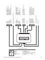
GREEN
DOOR TRIGGER INPUT ( - )
Locate the vehicle’s dome light or door pin switch wire.
Verification: This wire will register ground (NEG) when the door is opened
and the interior light is on. This wire will register positive voltage when the
door is closed and the interior light is off.
Connect the GREEN wire to the vehicle’s negative door input wire(s).
NOTE: Certain vehicles may require multiple connections. Refer to vehicle
application guide
4
YELLOW
IGNITION INPUT ( + )
Locate the vehicle’s ignition wire at the ignition switch.
Verification: This wire registers voltage when the key is turned to the ON (or
RUN) position. The voltage does not drop out when the key is turned to the
START (or CRANK) position.
Connect the YELLOW wire to the vehicle’s Ignition wire.
5
ORANGE
GROUND WHEN ARMED OUTPUT ( - )
This wire will have a continuous ( - ) 300mA output when the system is Armed. This
wire is typically used for controlling window modules or additional sensors.
6
RED/WHITE
TRUNK RELEASE OUTPUT ( - )
Locate the vehicle’s trunk release wire at the trunk release switch.
Verification: This wire will register either positive voltage or ground when
the trunk release is activated.
This is a low current output, 300mA.
2012 Audiovox Electronics Corporation. All rights reserved.
7