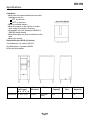
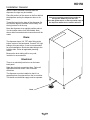
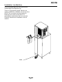
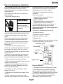
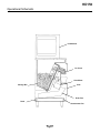
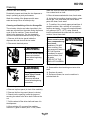
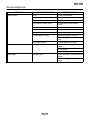
1
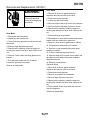
HD150
Introduction
To the owner or user: This product manual is a
source of information about the installation, start
up, cleaning, maintenance and repair of the
product.
The HD150 is a hotel/motel ice dispenser. It is
designed to use a Scotsman CME306 or CME456
ice machine as the source for ice.
Ice from the cuber falls into the insulated hopper,
where it is stored until needed. When a user
pushes the dispense button a rotating wheel
scoops the ice up to the top front of the hopper
where there is an outlet to the ice chute.
Table of Contents
Specifications/Limitations . . . . . . . . . . . . . . . . . . . . . . . . . . page 2
Installation . . . . . . . . . . . . . . . . . . . . . . . . . . . . . . . . page 3
Kits
. . . . . . . . . . . . . . . . . . . . . . . . . . . . . . . . . . page 5
Final Check List/Initial Start Up/Electrical Sequence
Cleaning
. . . . . . . . . . . . . . . page 7
. . . . . . . . . . . . . . . . . . . . . . . . . . . . . . . . page 8
Service Diagnosis . . . . . . . . . . . . . . . . . . . . . . . . . . . . . page 9
Removal and Replacement . . . . . . . . . . . . . . . . . . . . . . . . . page 10
Parts lists and wiring diagrams are located in the
center of this manual, printed on yellow paper.
Note the warning symbol where it appears in this
manual. It is an alert for important safety
information on a hazard that might cause serious
injury.
Keep this manual for future reference.
This manual was printed on recycled paper.
May 2000
Page 1
HD150
Specifications:
Limitations:
• Must meet the same limitations as the cuber
installed on top of it:
550F. air minimum,
Top View of HD150
1000F. air maximum.
• Must be installed indoors.
• Must allow space to the right for air intake
when using air cooled ice machine.
• Compatible only with Scotsman CME306 or
CME456 brand models.
• Must allow space for utility connections at the
back.
• Must have a drain.
Optional Kits (for HD150-1A) Include:
Coin Mechanism, kit number KSLDC2
Key Mechanism, kit number KSLDK2
All kits are field installed.
Model
Dimensions
Basic
(with legs)
Electrical
W x D x H
HD150S-1A 22" x 32" x 50" 115/60/1
Finish
Stainless
Steel
May 2000
Page 2
Ice Storage
Capacity
90 lb.
Max Fuse
Size
15
Min Circuit
Ampacity
2.9
HD150
Installation: General
After the carton has been removed from the
dispenser, the legs may be installed.
Place flat portions of the carton on the floor behind
the dispenser and lay the dispenser down on its
back.
Thread the legs into the base of the dispenser. Be
sure that the legs are screwed in all the way. Turn
the leg levelers in all the way.
Note
Remove any packing material from inside the
storage bin. Retain keys for later use.
Check that gasket tape is on the top outside edge of
the dispenser where the ice machine will rest.
Move the dispenser to an upright position and set
it in the location where it will be installed. Note
where drain lines and electrical connections will be
made.
Drain:
The dispenser has a 3/4" FPT drain fitting at the
bottom center of the back panel. Connect 3/4" rigid
tubing to this connection, a vent is recommended
for most installations. Route the drain tubing to the
building drain. Follow all applicable plumbing
codes.
Because the drain tubing will be very cold,
insulation is recommenced.
Electrical:
There is an electrical junction box on the lower
back panel
Make the electrical connections there. Follow all
applicable electrical codes. Use a licensed
electrician.
The dispenser must be installed so that it is a
separate piece of equipment from the ice machine.
The drains and electrical supply must be separate.
Drain
May 2000
Page 3
HD150
Installation: Ice Machine
Check that gasket tape has been placed at the
outside edge of the dispenser top.
There is no thermostat to install. Place the ice
machine (CME306 or CME456) onto the top of the
HD150. The ice machine will sense when ice
builds up into its cube port and shut off. It
automatically restarts when that ice is removed.
Follow all instructions for installation of the ice
machine.
Drain
May 2000
Page 4
HD150
Kits: Coin Mechanism (KSLDC2)
A kit is available to install a coin mechanism, and
another kit is available to install a room key
mechanism. Both come with detailed instructions,
summarized here:
Coin Mechanism, install after ice machine has
been operating:
1. Disconnect electrical power.
Electrical Shock Hazard.
Disconnect electrical
power before beginning
procedures.
mechanism and hold in the safety interlock switch.
Push the slide in and release it. The dispenser
should dispense ice into the container.
17. Check if the proper amount of ice was
dispensed.
If more ice is needed:
• Increase the time by turning the timer
adjustment dial clockwise.
If less ice is needed:
• Decrease the time by turning the timer
adjustment dial counter clockwise.
The initial setting should be 4 on the dial, or 8
seconds. Each segment equals 2 seconds.
Important: Disconnect the power supply when
adjusting the timer.
18. Place new schematic over the old one.
2. Locate key, unlock and remove sink. Then
remove the top front brace and control box cover.
19. Install the coin box.
19. Reconnect power to dispenser.
4. Remove all the wires from the push button
switch.
20. Replace control box cover.
21. Replace sink.
5. Remove the nuts that secure the push button
cover to the dispenser and remove the cover.
22. Check operation of coin box and key lock. After
everything is operating, give key to user.
6. Remove the screws that hold the push button
switch to the dispenser and remove the push
button switch.
Control Box Layout
7. Install the small cover plate from the kit.
Control Relay
8. Remove cover plate on right side of front panel,
below push button switch; use 5/16" nut driver.
9. Install the mounting plate fron the kit using the
nuts from the kit.
10. Secure the coin mechanism to the mounting
plate from the inside of the dispenser. Use the
screws, flat washers and lockwashers from the kit.
11. Remove the cover from the control box.
12. Remove the timer mechanism from the kit and
install it in the control box.
Coin Mech
Relay
Adjustment
Coin Mech
Timer
Agitation Timer
13. Remove wires numbered 8 and 9 from the
control box, they will be replaced by new wires
from the kit marked 8 and 9.
Electrical Sequence
14. Install the new wires, following the wiring
diagram from the kit.
2. Timer closes internal contacts, connecting
power to gearmotor (and door solenoid if -1B)
15. Reconnect the electrical power supply to the
machine.
3. Gearmotor rotates dispense wheel until internal
timer contacts (AND cam switch contacts if -1)
open. The time of rotation (and amount of ice
dispensed) is determined by the timer.
16. Place a container in the drop zone of the
dispenser. Place a quarter in the slide of the coin
1. Coin switch closes, connecting power to timer.
May 2000
Page 5
HD150
Key Kit Installation: (KSLDK2)
1. Disconnect electrical power
Electrical Shock Hazard.
Disconnect electrical
power before beginning
procedures.
2. Remove sink and drain pan.
3. Remove cover.
4. Remove control box cover
5. From kit, locate brass fitting. Obtain typical door
lock cylinder from the motel/hotel.
6. Insert cylinder into brass fitting (most cylinders
will fit). Mark place where cylinder sticks out past
brass fitting. Cut off excess cylinder.
7. Insert cylinder into hole on plate in kit. Place
switch mounting bracket behind cover plate and
over fitting, with the switch below the fitting. Using
the locknut provided, fasten the fitting in place with
the flats vertical.
8. Place the cylinder in the brass fitting, and
secure to the fitting with the set screw.
9. Push hotel/motel key into the cylinder and adjust
lever of micro switch so the switch closes when the
key is pushed all the way in.
10. Install plate and switch assembly into
dispenser. Secure with nuts removed from original
plate.
11. Remove wire #8 from normally open terminal
of the dispenser switch and reconnect it to the
normally open terminal of the room key
microswitch.
12. Disconnect wire #9 from the normally open
terminal of the dispense switch and connect it to
the normally open terminal of the room key switch.
13. Use wire #6 from kit, and connect the normally
open post of the dispense switch and common of
the room key switch
Install control box cover.
Replace drain pan and sink.
Reconnect power and check vending. Pushing key
in and holding vend button down should start vend.
May 2000
Page 6
HD150
Final Check List/Initial Start Up
1. Check that electrical power has been supplied.
2. Check that a drain, separate from the ice
machine, insulated and made of rigid tubing, has
been connected to the dispenser.
3. Check that the ice machine has been properly
installed per the ice machines installation
directions.
4. Check that the ice machine/dispenser assembly
is level front to back and left to right.
5. Check that optional kits, if any, have been
correctly installed.
6. Check that the sink key, and coin box key if
used, are available.
To Start:
1. Connect electrical power.
2. Go thru ice machine start up procedures. Let ice
machine make two harvests.
3. Push vend switch button in.
4. Rotor should rotate 1/4 turn and stop.
5. Ice will be dispensed from ice chute.
6. Remove sink, and check drain area for leaks. If
none, replace sink.
7. Fill out the warranty registration form and place
it in the mail.
8. Give the operator the key(s) and instructions on
the operation and maintenance of the product.
Check that the operator knows who to call for
service, and has the product/service manuals for
the machines.
Electrical Sequence
Pushing the vend button closes a contact to the
gear motor and to the ice door solenoid.
The gearmotor and ice door solenoid will have
power and the dispenser will continue to operate
as long as the dispense switch is pushed in. This
model also has a agitation cycle of 3 seconds
every 2 hours. The solenoid does not engage
during agitation and no ice is dispensed.
May 2000
Page 7
HD150
Operational Schematic
Ice Machine
Ice Chute
Gear Motor
Sink
Storage Bin
Drain Pan
Drain
Condensate Pan
May 2000
Page 8
HD150
Cleaning
General Care and Cleaning
Periodically inspect and clean the ice dispenser to
keep it operating at peak performance.
Wash the entire bin area and the delivery area.
Use a clean brush or cloth.
9. Rinse all areas washed with clean, fresh water.
10. Using the ice machine cleaning solution, clean
the ice grill, sink, and water pan. Rinse these
parts with clean, fresh water.
Wash the outside of the dispenser with warm
water and soap. Rinse off and wipe dry.
Cleaning and Sanitizing of the Ice Storage Bin:
The minerals, chlorine and other impurities in the
water are rejected from the water during the freeze
cycle of the ice machine. These minerals will
collect in the storage bin. The ice storage bin
should be cleaned and sanitized every 90 days.
1. Remove all of the ice stored inside the
dispenser bin and shut off the ice maker.
2. Disconnect electrical power
Electrical Shock Hazard.
Disconnect electrical
power before beginning
procedures.
11. To sanitize: Use a locally approved sanitizer. A
possible sanitizer: Mix a solution of ice machine
sanitizer and water: 1 ounce of household bleach
to 2 gallons of (95oF.-1150F.) water. Wash all
interior surfaces and the wheel with the sanitizer
solution. Use a clean cloth.
Scotsman Ice Machine
Cleaner contains acids.
These compounds may
cause burns.
If swallowed, DO NOT
induce vomiting. Give
large amounts of water or
milk. Call Physician
immediately. In case of
external contact, flush
with water.
KEEP OUT OF THE
REACH OF CHILDREN.
12. Allow the parts to air dry.
13. Reassemble wheel and large nut onto drive
shaft.
Moving parts in bin will
cause injury if hands
are in the way.
Disconnect electrical
power before beginning
procedures.
14. Replace all panels.
15. Reconnect power, be sure ice machine is
switched back on.
3. Locate key and remove sink.
4. Remove top front panel (in front of ice machine).
5. Remove the front top panel (above ice chute).
6. Reach into the opening, locate the large nut
securing the wheel to the drive shaft. Remove the
nut.
7. Pull the wheel off the drive shaft and leave it in
the dispenser.
8. Mix a solution of 5 ounces of ice machine
cleaner to 1 gallon of warm (95oF.-1150F.) water.
May 2000
Page 9
HD150
Service Diagnosis
PROBLEM
Does not vend
POSSIBLE CAUSE
No ice
No power
Vend switch open
Sink interlock switch open
Ice jams in chute
Front panel not on all the way
Gearmotor open
Ice door does not open
Coin Mechanism
Drive shaft broken
Does not vend, no ice
Leaks water
Bin drain leaks
May 2000
Page 10
PROBABLE FIX
Check ice machine
Check power supply
Check/replace vend switch
Check/replace sink interlock
switch
Machine is not level
Reinstall panel
Check/replace gearmotor
Check for power to solenoid.
Check linkage from solenoid to
door
Check/replace drive shaft.
Check the above, plus coin
switch
Check wiring
Check timer
Check bin drain connections and
fittings
Check for clogged bin drain
tubing
HD150
Removal and Replacement: HD150-1
Drive Shaft
Electrical Shock Hazard.
Disconnect electrical
power before beginning
procedures.
1. Remove all of the ice stored inside the
dispenser bin and shut off the ice maker.
2. Disconnect electrical power
3. Locate key and remove sink.
4. Remove top front panel (in front of ice machine).
5. Remove the front top panel (above ice chute).
Gear Motor
6. Reach into the opening, locate the large nut
securing the wheel to the drive shaft. Remove the
nut.
1. Disconnect electrical power
7. Disconnect wires at gearmotor.
2. Locate key and remove sink.
8. Mark position of cam switch bracket and remove
bracket with cam switch from gearmotor.
3. Trace wires from gearmotor to control box and
disconnect.
9. Remove 4 nuts securing gearmotor to cabinet.
4. Remove large dispenser top panel.
10. Pull gearmotor down and out of cabinet.
5. Reach into the opening, locate the large nut
securing the wheel to the drive shaft. Remove the
nut.
11. Remove six cap screws holding drive shaft
housing to cabinet.
6. Remove 4 nuts & bolts securing gearmotor to
bracket.
7. Pull gearmotor down and out of cabinet.
13. Remove snap ring from end of drive shaft, and
tap shaft out of bearings with plastic headed or
dead blow hammer.
8. Remove gearmotor from base.
14. Reverse to reassemble.
Reverse to reassemble.
Dispense Wheel
12. Pull drive shaft housing from the bin.
1. Remove all of the ice stored inside the
dispenser bin and shut off the ice maker.
2. Disconnect electrical power.
3. Remove ice machine from dispenser.
4. Remove large dispenser top panel.
5. Reach into the opening, locate the large nut
securing the wheel to the drive shaft. Remove the
nut.
6. Pull the wheel off the drive shaft and remove it
from the dispenser.
Reverse to reassemble..
May 2000
Page 11