1
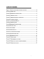
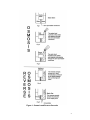
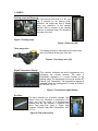
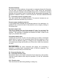
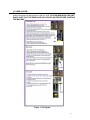
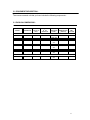
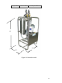
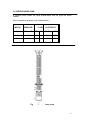
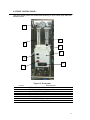
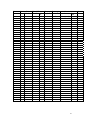
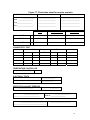
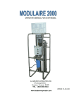
OPERATOR’S MANUAL 80 GPH
LEADER EVAPORATOR LTD.
49 Jonergin Drive
Swanton, Vermont 05488
TEL. : (802) 868-5444
www.leaderevaporator.com
VERSION 2005-02-02
TABLE OF CONTENTS
1.0
USER’S MODE FOR COMMERCIAL REVERSE OSMOSIS .......................................5
1.1 INTRODUCTION ........................................................................................5
1.2 HISTORY ................................................................................................5
1.3 FUNCTIONING .........................................................................................5
1.4 PARTS…………………………………………………………………………6
1.5 INSTALLATION.........................................................................................9
2.0 YEARLY START UP ...................................................................................... 10
3.0 USER GUIDE ............................................................................................... 11
3.1 CALCULUS OF % CONCENTRATION ........................................................12
3.2 MEMBRANE PERMEABILITY TEST ...........................................................13
3.3 ANNUAL CLOSING PROCEDURE..............................................................14
3.4 ANNUAL STORAGE WITH ANTIFREEZE .....................................................15
3.4.1 PRESERVATION SOLUTION..................................................................15
4.0 MANUFACTURE GUARANTIE ......................................................................... 16
5.0 EQUIPMENT DESCRIPTION ............................................................................ 17
5.1 PHYSICAL DIMENSIONNES .....................................................................18
5.2 OVERPRESSURE PUMP ..........................................................................19
5.3 MEMBRANE HOUSING ...........................................................................20
5.4 CONTROL PANNEL................................................................................21
5.5 PERFORMANCE LECTURE .....................................................................22
5.6 PRODUCTION SHEET FOR RO .................................................................26
5.7 CORRECTION FACTOR FOR MEMBRANES.................................................22
2
LISTE OF FIGURES
Figure 1. OSMOSIS AND REVERSE OSMOSIS PROCEDURE ........................................ 4
FIGURE 2. PRIMING PUMP.......................................................................................6
FIGURE 3. RESERVOIR IN STAINLESS STEEL .............................................................6
FIGURE 4. THREE WAYS VALVE...............................................................................6
FIGURE 5. TEMPERATURE DIGITAL CONTROLLER......................................................6
FIGURE 6. FILTER AND HOUSING .............................................................................6
FIGURE 7. LOW PRESSURE SWITCH.......... ..............................................................7
FIGURE 8. PRESSURE GAUGE.… ............................................................................7
FIGURE 9 MEMBRANE & PRESSURE PUMP……...... ..................................................7
FIGURE 10 CONTROL BOX..........… ........................................................................9
FIGURE 11 PICTOGRAM....……….........................................................................11
FIGURE 12. DATA RESULTS..................................................................................12
FIGURE 13. ILLUSTRATIVE UNIT MODEL .................................................................18
FIGURE 14 OVERPRESSURE PUMP......... ...............................................................19
FIGURE 15 MEMBRANE HOUSING......... .................................................................20
FIGURE 16. FRONT PANNEL .................................................................................21
FIGURE 17. PERFORMANCE UNIT TABLE ................................................................22
FIGURE 18. PRODUCTION
PAGE FOR REVERSE OSMOSIS ........................................25
FIGURE 19. CORRECTION FACTOR... .....................................................................27
3
Figure 1. Osmosis and Reverse Osmosis
4
1.0 USER’S MODE FOR COMMERCIAL REVERSE OSMOSIS
CONGRATULATIONS! You just acquired an LEADER EVAPORATOR reverse
osmosis. This proves your interest in new technologies and beautiful things.
In fact, you have purchased a technologically advanced unit built by skilled
professionals at A. Pellerin & Fils Ltée, who bring many years of research to the
use of reverse osmosis in maple syrup production..
1.1 INTRODUCTION :
Reverse osmosis is a process by which a solution’s natural tendency to scatter its
components uniformly is reversed. It occurs in the reverse osmosis because an
applied pressure forces the water through a semi-permeable membrane. The water
that does not pass through the membrane is left with all the sugar and thus called the
concentrate.
1.2 HISTORY :
The procedure of reverse osmosis was observed and studied since more than 200
years. Abbé Nolet a French scientist had experimented the basic phenomena around
1748. The scientists had figure out after long time, that the natural process could be
reversed and many applications could be dispose of in their research. This principle is
applied to the process of water desalination since the beginning of the 60’s.
1.3 FUNCTIONING :
How this unit works?
This is probably the first question that came to your mind as you opened this manual.
The sap provided by maple trees is a solution containing mostly water (96% to 98%),
2% to 3% sugar and small quantities of mineral salts, proteins and other elements
such as aroma. Sap is the solution in which you will increase the amount of sugar in
relation to the quantity of water. This will be done by extracting the water from the
maple tree sap. This separation process will give a more concentrated sap solution
(concentrate) and the portion of water which has been subtracted from the sap
(permeate).
5
1.4 PARTS :
Priming pump and Reservoir
All liquid amount inlet that is in the your
unit is pumped by the priming pump,
whatever, the maple sap that is coming
from your reservoir’s or the washing
solution that is founded in the washing
reservoir in stainless steel (CIP) located at
one side of the unit.
Figure 2. Priming pump
Figure 3. Reservoir (SS)
Three ways valve
The feeding process is effectuated by the three ways
valve (V6) located at the input of the unit.
Figure 4. Three ways valve (V6)
Digital Temperature Display
This controller evaluates the liquid’s temperature as it
penetrates the reverse osmosis. The value is
immediately displayed on a screen located on the
reading panel. The temperature must never exceed 49o
Celsius (120o Fahrenheit). The programming manual is
available inside the reading panel. It works at 50/60Hz,
AC100-240, 6.6 VA.
Figure 5. Temperature digital display
Pre Filter:
The sap is filtered by a 10 micron cartridge. This
clears it from any substance in suspension. The
sump and cap are made of a polypropylene
material and the cap includes a Pressure relief
valve. Flow rates from 1gpm to 15gpm. Max
Pressure: 100psi(6.9 bar). Max Temperature: 100F
(37.7C).
Figure 6. Filter and housing
6
Low pressure control
This control ensures that the filters are not obstructed by dirt
or micro-organisms. If such were the case, the machine
would stop by itself, thus protecting the pumps and
membranes
Figure 7. Low pressure Switch
Pressure Gauge
If this is the case, the machine (RO) will stop by itself protecting
the pump(s) and the membrane(s). A pressure gauge will allows
you to visualize the filter output pressure at the control panel, if
the pressure is lower than 12 pds./inch2 the unit will stop by itself.
Figure 8. Pressure gauge
Membrane and Pressure pump
The filtered water is pressurized with the help of the pressure pump.
The lower part of the pump creates what is called recirculation. This
gives the sap the necessary speed to clean the membrane surface
M5
automatically during the sap concentration process. The same thing
happens to the washing liquid during the soap and recirculation
washes. The sap is concentrated by the membranes resulting in a
sweeter sap (concentrate) and treated water (permeate). It is possible
to add more membranes just to increase your reverse osmosis
capacity.
Membrane
Pressure pump
Figure 9. Membrane and pressure pump
V2 : Concentrate flow regulating valve
As it comes out of the membrane, the concentrate sets out for the reading panel,
reaching a flow regulating valve. The flow will be measured by a flowmeter. You can
adjust the concentration percentage by regulating the concentrate flow. The sample
valve will allow you to determine the concentration that suits you.
Concentrate flowmeter
This flowmeter calculates the concentrate flow. The value, in gallons per minute
(GPM), is indicated on the reading panel
7
Permeate flowmeter
As it comes out of the membrane, the permeate is run directly through this flowmeter.
The flow value is indicated on the reading panel in GPM. During the concentration
process, the liquid is directed to the permeate storage basin. It is essential to know the
permeate and concentrate flows to calculate the sap concentration percentage. This
calculation is detailed in section 3.1 CALCULATION OF THE SAP CONCENTRATION
%.
V1 : Concentrate pressure regulating valve
This valve controls the concentrate pressure. The pressure increases as you
tighten the valve and decreases as you loosen it.
Pressure gauge (membrane pressure)
It is this gauge which evaluates the concentrate pressure in the membrane. It is
possible for you to know the value of this pressure (in psi.) simply by looking on
the reading panel.
Permeate sample valve
This valve is located at the top of the permeate V3 valve. You can know if the
reverse osmosis process is performed correctly by analyzing the permeate. For
example, if the membrane is damaged and therefore not able to retain all the
sugar, your permeate will be sweet.
Concentrate sample valve
Located at the top of the V4 valve, this valve allows you to obtain a concentrate
sample before it is sent into the concentrate basin. With this sample you will be
able to note the difference made by a change of the concentrate flow on the
concentration percentage and therefore you will be able to obtain the sweetness
you want.
Concentrate basin
After going through the valves, flowmeters and gauges, the concentrate is
directed to a storage basin (concentrate basin) to feed the evaporator. The
company does not provide you with this basin.
V3 : Permeate direction valve
V4 : Concentrate direction valve
The direction taken by the liquid is determined by the three-way valve position.
The black arrows indicate which ways the permeate (V3) and the concentrate
(V4) can go.
V19 : Direction valve
This valve directs the water during washing or rinsing only.
8
Control Box
The unit control is done by the an
electric control box, inside this box
all the electrical components are
included, such as : contacts, timer
relay, the temperature control, the
positional switches, the fuses,
etc.)
Figure 10. Control Box
1.5 INSTALLATION :
All the concentrators of ‘’A. PELLERIN et FILS’’ are delivery with a three way valve at
the input of the unit. You must provide the couplings for your basin in a way of
avoiding a restriction at the time of rising your unit, the waterproofness of the source
feeding must be verified in order to avoid the creation of vibrations that will cause a
deterioration of the pressure pump and the membrane. The maple sap is therefore
conducted by the source feeding pump from the basin just to the unit.
It is recommended to connect the filtrate basin and the maple sap by a common
source line, the flow of each basin will be controlled by a valve in each basin or
reservoir. This control will be connect directly to the input valve of your unit. It is
preferable to place the basin of water sap and filtrate in a way that the liquid pass with
gravity. In the unit, all the discharge inconvenient will be avoided in the source line
followed by a possible leak over this line.
The return lines for the filtrate and concentrate has to be installed just to the basin or
reservoir. It is preferable to be certain that there exist a slope towards the basin for
empting complete the lines, specially at evening time with the finality of avoiding
freezing effects. This lines, has to be washed, you have to prevent and eliminate the
outputs from the lines and basin. A drain has to be installed inside de room where the
concentrator is located, this with the finality of evacuate the water need for unit’s
rising.
A well lit, well heated, well ventilated, isolated shelter for the machine should be
planned in the saphouse. The entrance door dimensions must be calculated according
to the machine dimensions (see section 5.1). The shelter should be heated prior to
delivery and installation of the machine. The durability of the electrical components will
depend on the feeding quality. Therefore, it is very important to have your electrician
check your installations to make sure that they comply with the local electricity code
standards.
9
2.0 YEARLY START UP :
All the following procedures can be made with spring water (without Chlorine!)
or well water, as long as it is clean and does not stain.
Your machine has been filled with a glycol solution to prevent the membranes
and other components from freezing. The preparation of your system at the
beginning of each season must be carried out in the following way:
¾ Read the user’s manual completely.
¾ Call an electrician to connect the unit to an electrical source.
¾ Connect the unit to the maple sap, concentrate and filtrate basins.
¾ Connect the filtrate pipe beneath the membrane
¾ Plug in the machine and rinse the unit following the same process as for
membrane rinsing with half the number of water gallons your unit can
concentrate in an hour. For example, if your machine has an 8 inches
membrane, thus a 600 gallons per hour (GPH) capacity, rinse it with 300
gallons of water.
¾ Perform a washing without soap, reaching a water temperature of 460C
(1150F).
¾ Do a second rinsing cycle as soon as the washing cycle is finished.
¾ . Do a second washing without soap. It is very important to reach the
water temperature mentioned before.
¾ Do another rinsing cycle as soon as the washing cycle is finished.
¾ Do a third washing cycle, this time adding the soap. Make sure to reach
a temperature of 460C (1150F).
¾ Do a final rinsing cycle with half the number of water gallons your unit
can concentrate in an hour.
¾ Carry out a permeability test of membranes
1.
Fill the washing basin just to half of its capacity with filtrate.
2.
Concentrate the permeate at 200 PSI pressure. Returning the
permeate and concentrate to the washing basin. To do that, you must
position the valves in washing soap cycle, close valve V18 and adjust
the pressure to 200 pounds.
3.
Take down a reading of permeate flow when the temperature
reaches 130C (550F). This reading will indicate you the filtration capacity
of your membrane only without imply another factor such as
temperature, biofilms or bacteria. A permeability test at 210C (700F) and
150 PSI, will give you the same lecture.
4.
Compare the permeate flow value with the one taken when the unit
was manufactured or after you first utilisation during the season. You will
evaluate in this way the permeability of your membrane. This data will
be your reference for other successive tests.
¾ You are now ready to concentrate maple sap..
10
3.0 USER’S GUIDE :
This manual has been designed to help you work with your reverse osmosis. All of
these instructions are also printed on the unit. P.S. TO AVOID BREAKING THE UNIT,
MAKE SURE THAT THE PUMPS ARE FILLED WITH WATER BEFORE STARTING
THE MACHINE.
Figure 11. Pictogram
11
3.1 CALCULUS OF % CONCENTRATION :
The percentage of concentration is calculated in function of the filtrate flow quantity
and the total flow quantity that goes in the unit.
Operation data
Date
Density (Brix)
Flow (GPM)
Sap
Filtrate
Conc
Con
Temp.
Pressure
Concentrate
Degre F.
pds/inch2 % de Conc.
c.
1
Example 1
Example 2
Example 3
2
2.0
2.0
2.0
3
2.0
5.0
4.0
4
9.0
9.0
9.0
5
3.0
6.0
9.0
6
55
55
55
7
450
450
450
100x4/(4+5))
75%
60%
50%
Conc
.
or
Flow
GPH
60x(4+5) Test
720
900
1080
Figure 12. Data Results
20
15
10
5
0
Concentration Calculus
Flow
(gpm)
flow
(gpm)
Concentration Calculus
1
2
Example
3
Serie 1
Série2
Serie 2
Série1
30
20
10
0
Exemple
3
Example
1
2
Exemple
1 3
Example
Exemple
2
Example
1
2
3
Example
(filtrate flow)
)
(filtrate flow + concentrate flow)
Flow per hours = 60 x (filtrate flow + concentrate flow)
Concentration % = 100 x (
To facilitate the comprehension, we can take three examples : your unit process 9
gpm in the filtrate and you will like to adjust the concentrate to 3.6 or 9 gpm, what will
be the total flow concentration in % of the unit? (Using the data page) given above :
1) Permeate = 9gpm and concentrate= 3 gpm
% of concentration = 100 x ((9)/(3+9))
= 75% @ 720 gallons per hour
2) Permeate = 9 gpm and concentrate =6 gpm
% of concentration = 100 x ((9)/(6+9))
= 64% @ 840 gallons per hour
12
3)
Permeate = 9 gpm and concentrate = 9 gpm
% of concentration = 100 x ((9)/(9+9))
= 50% @ 1080 gallons per hour
IT’S VERY IMPORTANT TO REMEMBER THAT YOU HAVE TO TAKE NOTE OF
THE DATA EVERY OPERATION DAY THIS MEASURE HAS THE GOAL OF
DETECTING IMMÉDIATELY THE OPERATION DIFFICULTIÉS OF YOUR UNIT.
3.2 MEMBRANE PERMEABILITY TEST:
The filtration process and the membrane’s performance vary depending on the
type of membrane, exerted pressure on membrane, sap temperature, percentage
of sugar in the concentrate, and presence of other components such as bacteria,
biofilm and mineral salts. Therefore, it is important to maintain similar test
conditions for all samplings. To do so, we recommend that you use the following
method:
1.
Prepare a basin full of permeate obtained from sap concentration or
from clear, detritus free spring water.
2.
Rinse machine for 10 minutes with permeate so that only permeate
remains inside.
3.
Fill the washing basin just to half of its capacity with permeate.
4.
Concentrate the permeate at 200 PSI pressure. Returning the
permeate and concentrate to the washing basin. To do that, you must
position the valves in washing soap cycle, close valve V18 and adjust the
pressure to 200 pounds.
5.
Take down a reading of permeate flow when the temperature
reaches 130C (550F). This reading will indicate you the filtration capacity of
your membrane only without imply another factor such as temperature,
biofilms, or bacteria. A permeability test at 210C (700F) and 150 PSI, will
give you the same lecture. You can compare the permeate flow value with
the one taken when the unit was manufactured.
6.
Compare the permeate flow value from your test (no 5) to the same
test made at the factory or when you operated your machine for the first
time during the season. You will then be able to establish the exact
condition of your membrane.
13
3.3 ANNUAL CLOSING PROCESS
All of the following procedures can be made with spring water (without
Chlorine!) or well water, as long as it is clean and does not stain. Use as much
permeate water as possible to store your machine.
1
Rinse your machine with half the number of water gallons it can concentrate
per hour.
2 Wash the machine with the amount of soap recommended and let the
temperature raise up to 460C (1150F). Soap = 4 ounces per membrane.
3 Rinse your machine with half the number of water gallons it can concentrate
per hour.
4 Wash the machine with ACID and let the temperature raise up to 460C
(1150F). The unit should soak as long as possible (maximum 1 month).
5, 6, and 7 Do another rinse and wash soap cycle followed by another rinsing
as you had done in the three first steps.
Do a permeability membrane test.
¾ Fill the washing basin just to half of its capacity with permeate.
¾ Concentrate the permeate at 200 PSI pressure. Returning the
permeate and concentrate to the washing basin. To do that,
you must position the valves in washing soap cycle, close
valve V18 and adjust the pressure to 200 pounds.
¾ Take down a reading of permeate flow when the temperature
reaches 130C (550F). This reading will indicate you the filtration
capacity of your membrane only without imply another factor
such as temperature, biofilms or bacteria. A permeability test
at 210C (700F) and 150 PSI, will give you the same lecture.
¾ Compare the permeate flow value with the one taken when the
unit was manufactured or after you first utilisation during the
season. You will evaluate in this way the permeability of your
membrane.
8 If your membrane is clean, continue on step # 9. If you are not satisfied with
the cleanness of your membrane, you can pursue this process on step # 4
or simply send back the membrane to be CLEANED at the factory.
9 Put 20 litres of permeate in the washing basin and 4 litres of glycol or
glycerine. Add a teaspoon of preserve-osmo and let the water flow for 15
minutes. Then, stop your machine and HEAT the room all year between 50C
and 100C.
P.S.: If the room is subject to FREEZING, put 10 litres of glycol or glycerine for
each 4’’ x 40’’ membrane, 20 litres for each 8’’x40’’ membrane and 30 litres for
each 8’’x 60’’ membrane in the wash basin and let the liquid run inside the
machine (see annual storage with antifreeze).
14
3.6 ANNUAL STORAGE WITH ANTIFREEZE
It is possible to further insure adequate storage of your machine by storing it in a
glycol and water solution and following instructions for the soap washing
process. Before carrying out the annual storage process, you must be sure that
the machine has been thoroughly cleaned.
3.6.1 PRESERVATION SOLUTION
This preservation solution will protect the machine against freezing during the winter
months. The below table presents you the way to proceed.
Quantity
Description
20 liters
Glycol or glycerine for one membrane 8’’ x 40’’
30 liters
Glycol or glycerine for one membrane 8’’ x 60’’
½ ounce
Of préserve-osmo
Code
Quantity
Description
01260011
20 Liters
Glycol antifreeze alimentaire
01260051
4 Liters
Glycol antifreeze alimentaire
01260823
20 Liters
Glycerine alimentaire
01260824
4 Liters
Glycerine alimentaire
Proceed in the following way:
1. Valves positioned in washing soap cycle, with the exception of valve V19
(rinsing cycle)
2. Drain the washing basin.
3. Add the preservation solution.
4. To reduce the solution in the basin to 4 inches (bottom–up). Switch
position in manual operation by 15 seconds period allowing in this way,
the starting of the priming pump without the action of the pressure pump.
5. Valves position in washing soap cycle.
6. Do a solution circulation for a period of 10 minutes.
Following the above steps, drain the basin and the permeate output under the
membrane housing.
15
4.0 MANUFACTURER GUARANTIE :
The LEADER EVAPORATOR reverse osmosis units are guarantied by the
manufacturer against all fabrication vices for a period of two complete seasons,
starting with the installation date of the unit. The manufacturer’s responsibilities
concerning this guaranty are limited to the fixing or replacement of parts as one
desires by the manufacturer. All replaced pieces will be property of the manufacturer.
A. Pellerin & Fils Ltée. Will not be responsible for the damages that are results of
negligence, misuse, lack of respect in the operation mode in a factory that result in
damaging or injuries, or judicial pursuit.
16
5.0 EQUIPMENT DESCRIPTION :
The reverse osmosis unit that you have include the following components :
5.1 PHYSICAL DIMENSIONS :
MODEL
MEMBRANE
CAPACITY
GPD
MEMBRANE
2
PI OF
SURFACE
AE1014415C
1 X 4’’x40’’
2000
AE014430C
1 X 4’’x40’’
AE024430C
PRESSURE
PUMP
DIMENSIONS
(WxDxH)
PREFILTER
75
1.5 HP
110V, SS
28’’x25’’x52’’
1X10’’
2000
75
3 HP 220V,
SS
28’’x25’’x52’’
1X10’’
2 X 4’’x40’’
4000
150
3 HP 220V,
SS
28’’x25’’x52’’
1X10’’
AE034430C
3 X 4’’x40’’
6000
255
3 HP 220V,
SS
28’’x25’’x52’’
1X10’’
AE044430C
4 X 4’’x40’’
8000
300
3 HP 220V,
SS
28’’x25’’x52’’
1X10’’
17
Height : 52"
Width : 28"
Depth : 25"
52"
28"
25"
Figure 13. illustrative model
18
5.2 OVERPRESSURE PUMP :
A pressure pump allows the liquid pressurisation that will gives the desire
filtration.
Some examples of pressure pump characteristics :
MOTOR
PRESSURE
FLOW
ELECTRICITY
C.V
Pds/inch2
GPM
PH
VOLTS
AMPS.
5
450
10
1
230
20
7.5
450
16
1
230
30
Figure 14. Overpressure pump
19
5.3 MEMBRANE HOUSING :
The membranes are installed at the interior of a housing with the following
characteristics;
•
material : stainless steel........................................................... • dimension: 125 x 20 cm
•
membrane quantity by housing .......................................................................................1
01260007
Envelope 4”x40” in stainless steel
20
5.4 FRONT CONTROL PANEL :
The front control panel are constructed according to your needs, they have the
following items:
1
3
4
6
5
7
2
8
Figure 15. Front panel
CODE #
01090021 1
01151198 2
01260098 3
01260117 4
01150709 5
01260422 6
01150709 7
01150706 8
DESCRIPTION
PRESSURE INDICATOR (0-300 PSI)
TEMPERATURE DISPLAY
CONCENTRATE FLOWMETER
PERMEATE FLOWMETER
CONTROL BOX
FLOW VALVE V2
PRESSURE PUMP (white light)
HIGH TEMPERATURE (red light)
21
5.5 UNIT CONCENTRATION PERFORMANCE LECTURE :
The performance concentration lectures of the unit must be taking every time (day) that
you use the reverse osmosis unit. This lectures are primordial to assure an efficiency
maintenance of your membranes and to detect immediately all the lacunas at the time
operation of your unit. This lectures must be taking half hour after the beginning of the
concentration cycle. The following tables explain the procedure :
1) Date : data collection record day for the unit.
2) Sap density : in Brix degre when the temperature is 66oF.
3) Concentrate density : in Brix degre when the temperature is 66oF.
4) Concentrate flow : measure with a concentrate flowmeter lecture.
5) Permeate flow : measure with a permeate flowmeter lecture.
6) Water temperature : that is presently treated an the interior of the unit.
1.
Pressure in the membranes : measure with a manometer lecture "membrane pressure".
Density (Brix)
Sap Concen.
1
june 6 02
june 6 02
june 6 02
2
3
2.0
8.0
Flow (GPM)
Temp.
Filtrat
Con Degre F.
e
c.
4
5
6
7.5
55
7.5
2.5
55
Pressure
Lbs/po2
7
200
500
Concentrate
% de Concen. Flow
GPH
100x(4/(4+5)) 60x(4+5)
75%
600
75%
600
Figure 17. Unit performance table
22
Conc.
Or
Test
T
C
Date
1
Density (Brix)
Sap Concen.
2
3
Flow (GPM)
Temp.
Filtrate
Co Degre F.
nc.
4
5
6
Pressure
Po/inch2
7
Concentrate
Conc.
% de Concen. Flow
Or
GPH
100x(4/(4+5)) 60x(4+5) Test
23
Date
1
Density (Brix)
Sap Concen.
2
3
Flow (GPM)
Temp.
Filtrate
Conc. Degre F.
4
5
6
Pressure
Po/inch2
7
Concentrate
Conc.
% de Concen. Flow
Or
GPH
100x(4/(4+5)) 60x(4+5) Test
24
Figure 17. Production sheet for reverse osmosis
REVERSE OSMOSIS :
Membrane models
Serial number :
Serial number_______________
1._____________________
1.______________________
Model __________________
2._____________________
2.______________________
Pump __________________
3._____________________
3.______________________
Motor____________________
4._____________________
4.______________________
ACID
ALKALINE SOAPS
OXYDIZERS
Hydranautic PVD1
4 oz Acid-Osmo
4 oz Sani-Osmo
Filmtec NF70-BW30
4 oz Acid-Osmo
4 oz Sani-membrane
4 oz Oxy-membrane
Fluid System TFC
4 oz Acid-Osmo
4 oz Sani-membrane
4 oz Oxy-membrane
CONDUCTIVITY TEST
Membrane #
Conductivity
Concentrate Permeate
Temperature
o
F
Flow
Pressure
Permeate Concentrate
psi
1
2
3
4
TEMPERATURE CONTROLLER
Temperature 480C (1180F)
ELECTRICAL TESTS
Dielectric test
_________________OK
Total Amperage :
_______________Amps.
PROTECTION AGAINST FREEZING
Density :_________________
Temperature :__________
Salesman name :_________________
Buyer’s name :___________________
________________________________
Order # :__________________
Technician:_______________________________
Date________________________
_________________________________________
25
Fill up in case of malfunction
Our goal is to offer you an impeccable product. This is why every REVERSE
OSMOSIS machine is thoroughly inspected at the factory. We ask that you help us
improve our production methods by sending your comments to our production manager
at this fax number: (819) 828-3408.
Do not forget to send us the reverse osmosis production sheet with a description of the
problems encountered and their causes. We thank you in advance for your
collaboration.
Comments:
____________________________________________________________________
____________________________________________________________________
____________________________________________________________________
____________________________________________________________________
____________________________________________________________________
____________________________________________________________________
____________________________________________________________________
____________________________________________________________________
____________________________________________________________________
____________________________________________________________________
____________________________________________________________________
____________________________________________________________________
____________________________________________________________________
____________________________________________________________________
____________________________________________________________________
____________________________________________________________________
____________________________________________________________________
____________________________________________________________________
____________________________________________________________________
____________________________________________________________________
Technician : ___________________________
Date : _______________________
26
5.7 Correction factor for FLUID SYSTEM 8921S membrane
Temp
Factor
Machine capacity GPH) corrected according to the temperature
o
o
F
C
Corr. T
150
300
450
600
700
800 1000 1600
77
25
1,0000
216
433
649
865
1009 1154 1442 2307
75
24
1,0300
210
420
630
840
980 1120 1400 2240
73
23
1,0610
204
408
612
815
951 1087 1359 2175
72
22
1,0960
197
395
592
789
921 1053 1316 2105
70
21
1,1260
192
384
576
768
896 1025 1281 2049
68
20
1,1610
186
373
559
745
869
994 1242 1987
66
19
1,1960
181
362
543
723
844
965 1206 1929
64
18
1,2340
175
351
526
701
818
935 1169 1870
63
17
1,2720
170
340
510
680
794
907 1134 1814
61
16
1,3120
165
330
495
659
769
879 1099 1759
59
15
1,3540
160
319
479
639
745
852 1065 1704
57
14
1,3970
155
310
464
619
723
826 1032 1652
55
13
1,4420
150
300
450
600
700
800 1000 1600
54
12
1,4890
145
291
436
581
678
775
968
1549
52
11
1,5370
141
281
422
563
657
751
938
1501
50
10
1,5880
136
272
409
545
636
726
908
1453
48
9
1,6410
132
264
395
527
615
703
879
1406
46
8
1,6950
128
255
383
510
596
681
851
1361
45
7
1,7520
123
247
370
494
576
658
823
1317
43
6
1,8120
119
239
358
477
557
637
796
1273
41
5
1,8730
115
231
346
462
539
616
770
1232
39
4
1,9380
112
223
335
446
521
595
744
1191
37
3
2,0050
108
216
324
432
503
575
719
1151
36
2
2,0740
104
209
313
417
487
556
695
1112
34
1
2,1470
101
201
302
403
470
537
672
1075
To calculate the capacity of your unit : We suggest you to proceed in the following way :
The application formula is : Corrected Flow (GPH ) =
(Flow (GPH ))550 F *(Corr .T )550 F
(Corr . desired Temp. 0 F )
We can take an example to illustrate the formula application with the table showed above. You
need to find out the flow of any unit at one temperature of 20C (360F) for example. You must
take the flow value at 130C (550F) as a base value and multiply by the correction factor value
(1.4420) at this temperature. Finally, divide them by the correction factor value at the desired
temperature.
Data : Flow at 130C (550F) = 150 GPH, Temperature correction factor at 130C (550F) = 1,4420,
and the desired temperature value = 20C (360F). So the correction factor value at this
temperature is 2.0740.
Corrected Flow (GPH ) =
(150 GPH )550 F * (1.4420)
(2.0740)360 F
=
216.3
= 104 GPH
2.0740
Figure 18. Correction factor sheet
27
WASHING AND TAKING CARE OF YOUR MEMBRANES
1. WHEN TO WASH THE MEMBRANES?
The filtration process and thus the membrane’s performance vary depending on the type of
membrane, exerted pressure on membrane, sap temperature, percentage of sugar in the
concentrate, and presence of other components such as bacteria, biofilm and mineral salts.
Therefore, it is important to maintain similar test conditions in each sampling. To do so, we
recommend that you use the following method:
2.
TESTING METHODS :
¾
Fill the washing basin just to half of its capacity with filtrate.
¾
Concentrate the permeate at 200 PSI pressure. Returning the permeate and
concentrate to the washing basin. To do that, you must position the valves in
washing soap cycle, close valve V18 and adjust the pressure to 200 pounds.
¾
Take down a reading of permeate flow when the temperature reaches 130C
0
(55 F). This reading will indicate you the filtration capacity of your membrane only
without imply another factor such as temperature, biofilms or bacteria. A
permeability test at 210C (700F) and 150 PSI, will give you the same lecture.
¾ Compare the permeate flow value with the one taken when the unit was
manufactured or after you first utilisation during the season. You will evaluate in
this way the permeability of your membrane.
3. .. WASHING FREQUENCY :
It is often difficult for the user to determine when and how to wash the membranes
because the operating conditions vary according to many environmental factors. We
have thus established a simple and efficient method to keep your membrane clean
without putting it through a lot of washes. Otherwise it would wear out prematurely.
4 SOAP WASH :
The LEADER EVAPORATOR soap wash is the key process to keeping your membrane
clean. LEADER EVAPORATOR soap has been specially conceived to clean your
membrane while providing the best capacity (in gallons per hour)/longevity ratio. This
type of wash is efficient when the temperature reaches 430C (110 degrees F) but does
not exceed 460C (1150F) because this could change its properties. The recommended
washing time is 30 to 45 minutes. It is more important that you be sure to have the right
temperature conditions and the right amount of soap: increasing the soap wash time
or using another soap than LEADER EVAPORATOR soap could destroy your
membrane.
5 RECIRCULATION WASH
During this type of washing, in recirculation mode, the water contained in the permeate
basin runs through the whole machine at the lowest possible pressure for 8 to 12 hours.
6 ACID WASH :
The acid wash is a very important process to keep your membrane clean. It helps getting
rid of the biofilm and bacteria that develop when there are hotter periods in the season.
To be efficient, the Osmo acid soaking has to last at least 8 hours. It can go on without
damaging the membrane for up to four weeks. The acid wash is carried out following the
soap wash mode.
28
Reverse Osmosis operation
Concentration
Sugar removal in membrane
Rinse
Rinsing and
Recirculation
Soap
Daily wash
Rinsing with permeate 12 hrs.
Soap wash
Rinse
Rinse
Permeability test 200 pds./sq.in.
YES
Intensive wash cycle
NO
Loss
>15%
Acid or oxydizing wash
Rinse 20 min.
Cleaning Quantity product used par
membrane
Soap wash
Rinse 20 min.
Acid
Soap
Oxydizer
4'’ x 40’’
2 oz.
2 oz.
2 oz.
8'’ x 40’’
4 oz.
4 oz.
4 oz.
8' x 60’’
4 oz.
4 oz.
4 oz.
Hydranautic
Membrane
PVD1
Acid
Acid-osmo
Soap
Sani-osmo
Sanimembrane
Sanimembrane
Test 200 pds./sq.in.
Clean
Loss
>15%
Dirty
Restart intensive wash
next day
Filmtec
Koch
NF70-BW30 Acid-osmo
TFC
Acid-osmo
Oxydizer
------Oxymembrane
Oxymembrane
29


![Descargar - [ [ [ ANSEL ] ] ]](http://vs1.manualzilla.com/store/data/006268413_1-12223cddaa3301670b0a8998e4e61ac5-150x150.png)