1
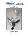
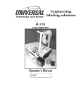
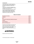
OPERATOR’S MANUAL FOR MODEL 500-1000 GPH
LEADER EVAPORATOR LTD.
49 Jonergin Drive
Swanton, Vermont 05488
(802) 868-5444
www.leaderevaporator.com
VERSION 2005-02-02
OPERATOR’S MANUAL FOR A REVERSE OSMOSIS 2000
TABLE OF CONTENTS________________________
1. MODULAIRE 2000 USER’S MANUEL...................................................... 5
1.1 INTRODUCTION ....................................................................................... 5
1.2 BACKGROUND.......................................................................................... 5
1.3 OPERATION ............................................................................................... 5
1.4 INSTALLATION : .................................................................................... 11
2. YEARLY START UP................................................................................... 12
3. USER’S GUIDE ............................................................................................ 13
3.1 GUIDE FOR 1HP PUMP.......................................................................... 13
3.2 GUIDE FOR 3HP PUMP.......................................................................... 15
3.3 CALCULATION OF SAP CONCENTRATION % .............................. 17
3.4 MEMBRANE PERMEABILITY TEST ................................................. 18
3.5 ANNUAL CLOSING PROCESS ............................................................. 19
3.6 PRESERVATION SOLUTIION.............................................................. 20
3.7 ANNUAL STORAGE PROCESS ............................................................ 20
4. MANUFACTURER WARRANTY ............................................................ 20
5. EQUIPEMENT DESCRIPTION ................................................................ 22
5.1 PHYSICAL DIMENSIONS...................................................................... 22
5.2 PRE-FILTER ............................................................................................. 24
5.3 PRESSURE PUMP.................................................................................... 25
5.4 MEMBRANE CASING ............................................................................ 26
5.5 READING PANEL.................................................................................... 27
5.6 ELECTRICAL BOARD ........................................................................... 28
5.7 OPERATION DATA.................................................................................. 29
APPENDIX 1. SERIAL EXPANSION KIT AND EXPANSION MODULE39
APPENDIX 2. PIPE INSTALLATION SUGGESTIONS………………..40
2
LIST OF FIGURES___ _____________________________
FIGURE 1. OSMOSIS AND
REVERSE OSMOSIS ......................................................... 4
FIGURE 2. FUNCTIONING OF THE 600 GAL REVERSE OSMOSIS .............................. 6
FIGURE 2. SERIAL FUNCTIONING WITH EXPANSION KIT (SEE APPENDIX 1)*…………. 6
FIGURE 3. FEEDING PUMP 1HP (P7) ...................................................................... 7
FIGURE 4 . TEMPERATURE CONTROLLER (S8) ...................................................... 7
FIGURE 5. PRE-FILTER ........................................................................................... 8
FIGURE 6. PRESSURE CONTROL (C11) ................................................................... 8
FIGURE 7. MEMBRANE (M5) .................................................................................. 9
FIGURE 8. FILTER ................................................................................................. 11
FIGURE 9. COUPLING TABLE ................................................................................ 11
FIGURE 10. PICTOGRAM....................................................................................... 16
FIGURE 11. DATA RESULTS .................................................................................. 17
FIGURE 12. REVERSE OSMOSIS UNIT .................................................................... 23
FIGURE 13. PRE-FILTER (10 MICRONS) ............................................................... 24
FIGURE 14. PRESSURE PUMP ................................................................................ 25
FIGURE 15. MEMBRANE HOUSING ....................................................................... 26
FIGURE 16. READING PANNEL .............................................................................. 27
FIGURE 17.ELECTRICAL BOARD FOR 600 GAL .................................................... 28
FIGURE 18. OPERATION DATA.............................................................................. 29
FIGURE 19. PRODUCTION SHEET FOR REVERSE OSMOSIS ................................... 36
FIGURE 20. CORRECTION FACTOR SHEET ........................................................... 38
FIGURE 21. SERIAL AND PARALLEL FUNCTIONING.............................................. 39
FIGURE 22 : SERIAL EXPANSION KIT 8” X 40” .................................................... 41
FIGURE 23. INSTALLATION DIAGRAM (1) ............................................................ 43
FIGURE 24. INSTALLATION DIAGRAM (2) ............................................................ 43
FIGURE 25. VALVES .............................................................................................. 44
3
Figure 1. Osmosis and reverse osmosis
4
1. MODULAIRE 2000 USER’S MANUEL
CONGRATULATIONS! You just acquired an LEADER reverse osmosis. This proves your
interest in new technologies and beautiful things.
In fact, you have purchased a technologically advanced unit built by skilled
professionals at LEADER EVAPORATOR LTD., who bring many years of research to the
use of reverse osmosis in maple syrup production.
1.1 INTRODUCTION
Reverse osmosis is a process by which a solution’s natural tendency to scatter its
components uniformly is reversed. It occurs in the reverse osmosis because an applied
pressure forces the water through a semi-permeable membrane. The water that does not
pass through the membrane is left with all the sugar and thus called the concentrate.
1.2 BACKGROUND
The reverse osmosis process has been observed and studied for more than 250 years.
Father Nolet, a French scientist, carried out experiments on the osmosis phenomenon
around 1748. The scientists have realized long ago that this process could be reversed and
that many applications could flow from this research. The principle of reverse osmosis has
been applied to the desalination of water since the beginning of 1960.
1.3 OPERATION
How does it work?
This is probably the first question that came to your mind as you opened this manual. The
sap provided by maple trees is a solution containing mostly water (96% to 98%), 2% to 3%
sugar and small quantities of mineral salts, proteins and other elements such as aroma. Sap
is the solution in which you will increase the amount of sugar in relation to the quantity of
water. This will be done by extracting the water from the maple tree sap. This separation
process will give a more concentrated sap solution (concentrate) and the portion of water
which has been subtracted from the sap (permeate).
5
Figure 2a. Functioning of the 600 gallons. reverse osmosis
Figure 2b. Functioning with serial expansion kit (see appendix 1)*
*Even if certain components appear in different quantities, the functioning of the
500 gal to 1000 gal reverse osmosis is the same.
6
V6 : Inlet valve
Three basins (washing, permeate and sap) are connected to this three-way valve, located
at the machine inlet. The origin of the liquid entering the reverse osmosis unit is
determined by the valve’s position.
V6
B20: Wash basin
This basin, located above the feeding pump, stores the
washing liquid. *The soap and recirculation washes are
explained in the USER’S GUIDE section.
Figure 3. Feeding pump 1HP (P7)
P7 : Feeding pump
All of the liquid entering your machine – sap, washing liquid or permeate – goes through
the feeding pump that gives it the impulse necessary to pursue its way inside the reverse
osmosis.
Sap and permeate basins
The sap basin contains the maple tree sap. The permeate basin is filled with the water
extracted from the sap during the concentration procedure. We recommend that the sap
and permeate basins be connected with a common feeding pipe connected directly to the
inlet valve (V6) of your machine. We also recommend that the permeate basin be able to
contain at least twice the modulaire’s capacity. It is preferable to place the maple sap and
permeate basins in such a way that gravity will cause the liquids to run. By doing this you
will not have to provide your machine with an additional pump pushing the fluids up to the
valve V6. Please note that the sap and permeate basins are not supplied by the company.
Sap and permeate pipes
Return lines have to be installed up to the permeate and concentrate basins. These lines
must be emptied. Here is a suggestion that will help you to succeed. Place the V19 valve
in rinse position, V3 and V4 valves half-way between two positions at a 45 degree angle.
The position of the V6 and V18 valves is not important. This will send all liquid in the pipes
to the drain. You must be able to get these lines out of the basins so that the liquid
contained in those basins is not drained during the process.
By following the paragraph below, it will possible to wash the sugar residue from the
concentration pipe. Here is a way of doing it. First of all, make sure to install the pipe in a
drain or a basin that can be emptied. At the end of the RO wash, put V4 valve in
concentration position. This will send the hot water from the wash into the concentrate
pipe instead of the drain. Repeat this procedure in rinse mode. (To do this operation close
the valve V18 partially).
Sap and permeate basin valves
The flow of those basins must be controlled by a valve situated under each one.
Figure 4 . Temperature controller (S8)
S8
7
S8 : Temperature controller
This controller evaluates the liquid’s temperature as it penetrates the reverse osmosis.
The value is immediately displayed on a screen located on the reading panel. The
temperature must never exceed 49o Celsius (120o Fahrenheit). The programming manual
is available inside the reading panel.
J28: Pressure Gauge
This gauge measures the pressure provided at the feeding pump. Its value is indicated on
the reading panel.
F9 : Pre-filter
The sap is filtered by a 10 micron cartridge. This clears it from any
substance in suspension.
F9
Figure 5. Pre-filter
C11 : Low Pressure control
This control ensures that the filters are not obstructed by dirt or
micro-organisms. If such were the case, the machine would stop
by itself, thus protecting the pumps and membranes.
Figure 6. Pressure control (C11)
C11
J10 : Pressure gauge
This gauge allows you to read the pressure at the filters’ outlet. Should it drop below 12
psi (82,737kPa), the machine will stop by itself.
P12 : Pressure pump
The filtered water is pressurized with the help of the pressure pump. The lower part of the
pump creates what is called recirculation. This gives the sap the necessary speed to clean
the membrane surface automatically during the sap concentration process. The same
thing happens to the washing liquid during the soap and recirculation washes.
M5
M5 : Membrane
The sap is concentrated by the membranes resulting in a sweeter
sap (concentrate) and treated water (permeate). It is possible to
add a serial expansion kit to increase your reverse osmosis
capacity (see appendix 1).
V2 : Concentrate flow regulating valve
As it comes out of the membrane, the concentrate sets out for the
reading panel, reaching a flow regulating valve. The flow will be
measured by a flowmeter (D24). You can adjust the concentration
percentage by regulating the concentrate flow. The sample valve
V32 will allow you to determine the concentration that suits you.
8
Figure 7. Membrane (M5)
D24 : Concentrate flowmeter
This flowmeter calculates the concentrate flow. The value, in gallons per minute (GPM), is
indicated on the reading panel
D23 : Permeate flowmeter
As it comes out of the membrane, the permeate is run directly through this flowmeter. The
flow value is indicated on the reading panel in GPM. During the concentration process, the
liquid is directed to the permeate storage basin. It is essential to know the permeate and
concentrate flows to calculate the sap concentration percentage. This calculation is
detailed in section 3.1 CALCULATION OF THE SAP CONCENTRATION %.
V1 : Concentrate pressure regulating valve
This valve controls the concentrate pressure. The pressure increases as you tighten the
valve and decreases as you loosen it.
J29: Pressure gauge (membrane pressure)
It is this gauge which evaluates the concentrate pressure in the membrane. It is possible
for you to know the value of this pressure (in psi.) simply by looking on the reading panel.
V31 Permeate sample valve
This valve is located at the machine outlet, more precisely on the manifold near the V3
and V4 valves. You can know if the reverse osmosis process is performed correctly by
analyzing the permeate. For example, if the membrane is damaged and therefore not able
to retain all the sugar, your permeate will be sweet.
V32 Concentrate sample valve
Located at the machine outlet, after the V4 valve, this valve allows you to obtain a
concentrate sample before it is sent into the concentrate basin. With this sample you will
be able to note the difference made by a change of the concentrate flow on the
concentration percentage and therefore you will be able to obtain the sweetness you want.
Concentrate basin
After going through the valves, flowmeters and gauges, the concentrate is directed to a
storage basin (concentrate basin) to feed the evaporator. The company does not provide
you with this basin.
V3 : Permeate direction valve
V4 : Concentrate direction valve
The direction taken by the liquid is determined by the three-way valve position. The black
arrows indicate which ways the permeate (V3) and the concentrate (V4) can go.
V18 : Drain valve
This valve is closed during the concentration process. It is open while washing or rinsing.
V19 : Direction valve
This valve directs the water during washing or rinsing only.
MANUAL OPERATING : When selecting this operating mode, you choose the starting time
of your machine. The feeding pump sill start first and then, pressure pumps will start
sequentially.
9
AUTOMATIC OPERATING: In the automatic operating mode, the machine can start
automatically when the sap basin is full and stop by itself when it is empty. Manual
adjustments have to be made first.
TIMER: By setting the timer, you choose your RO’s operating duration.
You will find an image accompanied by a short description of the reading panel in section
5.5. The selector (# 11) is used for the manual and automatic operating. The position of
the washing timer (#2) is also shown on this page.
10
1.4 INSTALLATION :
All the Leader Evaporator modulaires are delivered with three-way valves at the inlet and
outlet of the machine. The permeate and sap basin pipe ought to be connected to a filter
(figure 8). The latter must be connected to the V6 valve if this is not already done when you
receive your machine. The pipe diameter has to be equal to or greater than that of the filter
installed on the machine (see table below). You must plan your connecting pipes to prevent
restriction during the rinse and concentration cycles. Watertightness of the feeding pipe
must be checked to prevent vibrations which could cause pressure pump and membrane
deterioration. The table below shows the coupling dimensions.
Valve allowing the relief of the air in the
pipes.
Figure 8. Filter
V6 Valve
Connect the sap and permeate pipe to this end.
This part can be unscrewed to clean the filter inside.*
Capacity, # model Input
80 -160 (GPH)
1’’
LYNX
1½’’
150 – 600 (GPH)
Modular 2000
1½’’
600 – 1000 (GPH)
Modular 2000
2’’
plus 10 Brix
1600 (GPH)
3’’
Modular 2000
2400 - 3200 (GPH)
Permeate
¾’’
1’’
Concentrate Drain
¾’’
1’’
1’’
1’’
Overflow
11/2
11/2
1’’
1’’
1’’
11/2
1¼’’
1’’
11/2’
2
1½’’
1¼’’
11/2’’
2
Figure 9. Coupling table
*We suggest that you wash the filter every day you use your RO.
11
A well lit, well heated, well ventilated, isolated shelter for the machine should be planned in
the saphouse. The entrance door dimensions must be calculated according to the
machine dimensions (see section 5.1). The shelter should be heated prior to delivery and
installation of the machine. The durability of the electrical components will depend on the
feeding quality. Therefore, it is very important to have your electrician check your
installations to make sure that they comply with the local electricity code standards.
2. YEARLY START UP
All the following procedures can be made with spring water (without Chlorine!) or well
water, as long as it is clean and does not stain.
Your machine has been filled with a glycol solution to prevent the membranes and other
components from freezing. The preparation of your system at the beginning of each
season must be carried out in the following way:
¾ Read the user’s manual completely.
¾ Call an electrician to connect the unit to an electrical source.
¾ Connect the unit to the maple sap, concentrate and filtrate basins.
¾ Connect the filtrate pipe beneath the membrane.
¾ Plug in the machine and rinse the unit following the same process as for
membrane rinsing with half the number of water gallons your unit can
concentrate in an hour. For example, if your machine has an 8 inches
membrane, thus a 600 gallons per hour (GPH) capacity, rinse it with 300
gallons of water.
¾ Perform a washing without soap, reaching a water temperature of 460C
(1150F).
¾ Do a second rinsing cycle as soon as the washing cycle is finished.
¾ Do a second washing without soap. It is very important to reach the
water temperature mentioned before.
¾ Do another rinsing cycle as soon as the washing cycle is finished.
¾ Do a third washing cycle, this time adding the soap. Make sure to reach
a temperature of 460C (1150F).
¾ Do a final rinsing cycle with half the number of water gallons your unit
can concentrate in an hour.
¾
Carry out a permeability test of membranes
1. Fill the washing basin just to half of its capacity with filtrate.
2. Concentrate the permeate at 200 PSI pressure. Returning the permeate
and concentrate to the washing basin. To do that, you must position the
valves in washing soap cycle, close valve V18 and adjust the pressure to
200 pounds.
3. Take down a reading of permeate flow when the temperature reaches
130C (550F). This reading will indicate you the filtration capacity of your
membrane only without imply another factor such as temperature,
biofilms or bacteria. A permeability test at 210C (700F) and 150 PSI, will
give you the same lecture.
4. Compare the permeate flow value with the one taken when the unit was
manufactured or after you first utilisation during the season. You will
evaluate in this way the permeability of your membrane. This data will be
your reference for other successive tests.
¾ You are now ready to concentrate maple sap.
12
3. USER’S GUIDE
This manual was designed to help you work with your reverse osmosis. All of these
instructions are also printed on the front of your machine.
N.B. TO AVOID BREAKING THE UNIT, MAKE SURE THAT THE PUMPS ARE
FILLED WITH WATER BEFORE STARTING THE MACHINE.
3.1 GUIDE FOR 1HP PUMP
13
14
3.2 GUIDE FOR 3HP PUMP
15
Figure 10. Pictogram
16
3.3 CALCULATION OF SAP CONCENTRATION %
The concentration percentage is calculated in terms of the permeate and concentrate
flows.
Operation data
Date
1
Example 1
Example 2
Example 3
Density (Brix)
Flow (GPM)
Temp.
Sap
Conc
Permeate
Conc.
2
2.0
2.0
2.0
3
8.0
5.0
4.0
4
9.0
9.0
9.0
5
3.0
6.0
9.0
F Degrees
Pressu
re
psi
Concentrate
Conc %.
6
55
55
55
7
300
300
300
100x(4/(4+5))
75%
60%
50%
Conc.
Flow
GPH
60x(4+5)
720
900
1080
or
Test
C
C
C
T
Concentration calculus
30
20
10
0
Concentration calculus
Concentration
calculation
20
Exemple
3
Example
1
2
3
3
Exemple
2 2
Example
Example
Exemple
1 1
Flow
(gpm)
Flow
(gpm)
Concentration calculation
10
0
Examples
1
2
Example
3
Concentrate
Concentré
Permeate
Filtrat
Figure 11. Data results
(Permeate flow)
)
(Permeate flow + Concentrate flow)
Hour flow = 60 x (permeate flow + concentrate flow)
% = 100 x (
%Concentration
of concentration
Here are three examples to facilitate your comprehension: your machine treats 9 gpm
of permeate and you set the concentrate at 3, 6 or 9 gpm. What will be the
concentration percentage and the total flow of the machine? Let us use the data sheet
above:
1) filtrate = 9gpm and concentrate= 3 gpm
Concentration % = 100 x ((9)/(3+9))
= 75% @ 720 gallons per hour
2) filtrate = 9 gpm of concentrate =6 gpm
17
Concentration % = 100 x ((9)/(6+9))
=64% @ 840 gallons per hour
3) filtrate = 9 gpm and concentrate = 9 gpm
Concentration % = 100 x ((9)/(9+9))
= 50% @ 1080 gallons per hour
IT IS VERY IMPORTANT THAT YOU REMEMBER TO TAKE THIS DATA
EVERY DAY YOU USE YOUR REVERSE OSMOSIS. THIS WILL ENABLE
YOU TO DETECT ANY OPERATIONAL DIFFICULTY.
3.4 PERMEABILITY TEST OF MEMBRANES
The filtration process and the membrane’s performance vary depending on the type of
membrane, exerted pressure on membrane, sap temperature, percentage of sugar in
the concentrate, and presence of other components such as bacteria, biofilm and
mineral salts. Therefore, it is important to maintain similar test conditions for all
samplings. To do so, we recommend that you use the following method:
1)
Prepare a basin full of permeate obtained from sap concentration or from clear,
detritus free spring water.
2)
Rinse machine for 10 minutes with permeate so that only permeate remains
inside.
3)
Fill the washing basin just to half of its capacity with filtrate.
4)
Concentrate the permeate at 200 PSI pressure. Returning the permeate and
concentrate to the washing basin. To do that, you must position the valves in
washing soap cycle, close valve V18 and adjust the pressure to 200 pounds.
5)
Take down a reading of permeate flow when the temperature reaches 130C
(550F). This reading will indicate you the filtration capacity of your membrane only
without imply another factor such as temperature, biofilms, or bacteria. A
permeability test at 210C (700F) and 150 PSI, will give you the same lecture. You
can compare the permeate flow value with the one taken when the unit was
manufactured.
6)
Compare the permeate flow value from your test (no 5) to the same test made at
the factory or when you operated your machine for the first time during the
season. You will then be able to establish the exact condition of your membrane.
18
3.5 ANNUAL CLOSING PROCESS
All of the following procedures can be made with spring water (without Chlorine!) or
well water, as long as it is clean and does not stain. Use as much permeate water
as possible to store your machine.
1
Rinse your machine with half the number of water gallons it can concentrate
per hour.
2 Wash the machine with the amount of soap recommended and let the
temperature raise up to 460C (1150F). Soap = 4 ounces per membrane.
3 Rinse your machine with half the number of water gallons it can concentrate
per hour.
4 Wash the machine with ACID and let the temperature raise up to 460C
(1150F). The unit should soak as long as possible (maximum 1 month).
5, 6, and 7 Do another rinse and wash soap cycle followed by another rinsing
as you had done in the three first steps.
Do a permeability membrane test.
¾ Fill the washing basin just to half of its capacity with filtrate.
¾ Concentrate the permeate at 200 PSI pressure. Returning the
permeate and concentrate to the washing basin. To do that,
you must position the valves in washing soap cycle, close
valve V18 and adjust the pressure to 200 pounds.
¾ Take down a reading of permeate flow when the temperature
reaches 130C (550F). This reading will indicate you the filtration
capacity of your membrane only without imply another factor
such as temperature, biofilms or bacteria. A permeability test
at 210C (700F) and 150 PSI, will give you the same lecture.
¾ Compare the permeate flow value with the one taken when the
unit was manufactured or after you first utilisation during the
season. You will evaluate in this way the permeability of your
membrane.
8 If your membrane is clean, continue on step # 9. If you are not satisfied with
the cleanness of your membrane, you can pursue this process on step # 4
or simply send back the membrane to be CLEANED at the factory.
9 Put 20 litres of permeate in the washing basin and 4 litres of glycol or
glycerine. Add a teaspoon of préserve-osmo and let the water flow for 15
minutes. Then, stop your machine and HEAT the room all year between 50C
and 100C.
P.S.: If the room is subject to FREEZING, put 20 litres of glycol or glycerine for
each 8’’x40’’ membrane and 30 litres for each 8’’x 60’’ membrane in the wash
basin and let the liquid run inside the machine (see annual storage with
antifreeze).
19
3.6 ANNUAL STORAGE WITH ANTIFREEZE
It is possible to further insure adequate storage of your machine by storing it in a glycol
and water solution and following instructions for the soap washing process. Before
carrying out the annual storage process, you must be sure that the machine has been
thoroughly cleaned.
3.6.1 PRESERVATION SOLUTION
This preservation solution will protect the machine against freezing during the winter
months. The below table presents you the way to proceed.
Quantity
Description
20 liters
Glycol or glycerine for one membrane 8’’ x 40’’
30 liters
Glycol or glycerine for one membrane 8’’ x 60’’
½ ounce
Of préserve-osmo
Code
Quantity
Description
01260011
20 Liters
Glycol antifreeze alimentaire
01260051
4 Liters
Glycol antifreeze alimentaire
01260823
20 Liters
Glycerine alimentaire
01260824
4 Liters
Glycerine alimentaire
Proceed in the following way:
1. Valves positioned in washing soap cycle, with the exception of valve V19
(rinsing cycle)
2. Drain the washing basin.
3. Add the preservation solution.
4. To reduce the solution in the basin to 4 inches (bottom–up). Switch
position in manual operation by 15 seconds period allowing in this way,
the starting of the priming pump without the action of the pressure pump.
5. Valves position in washing soap cycle.
6. Do a solution circulation for a period of 10 minutes.
Following the above steps, drain the basin and the permeate output under the
membrane housing
20
4. MANUFACTURER WARRANTY
Reverse osmosis machines are guaranteed by their manufacturer against all
workmanship defects for a period of two complete seasons, starting on the installation
date of the machine. The manufacturer’s responsibility regarding this warranty is limited
to the repair or replacement of parts when he should consider it necessary to do so. All
replaced parts become the manufacturer’s property. Leader Evaporator Ltd shall not
be held responsible for any damage or injury arising from negligence, abuse, improper
handling or installation.
21
5. EQUIPEMENT DESCRIPTION
Your reverse osmosis unit includes the following components :
5.1 PHYSICAL DIMENSIONS
MODEL
MEMBRANE
CAPACITY
MEMBRANE
2
FEEDING
PRESSURE
TOTAL
DIMENSIONS
PRE-
GPH
FT OF SURF.
PUMP
PUMP
AMP
W x DEPTH x H
FILTER
AE124450
2 x 150
300
150
5CV
26 AMP
29"x34"x69"
1X20"
AE134450
3 x 150
450
225
5CV
26 AMP
29"x34"x69"
1X20"
AE118450
1 x 600
500
400
5CV
26 AMP
29"x42"x72"
2X20"
AE118475
1 x 600
600
400
7.5CV
37 AMP
29"x42"x72"
2X20"
AE318475
1 x 600
600
400
7.5CV
44 AMP
29"x42"x72"
2X20"
AE328475
2 x 600
1000
800
7.5CV
44 AMP
29"x42"x72"
2X20"
AE5384D75
3 x 600
1600
1200
2 X 7.5CV
81 AMP
30"x73"x72"
4X20"
AE5484D75
4 x 600
2000
1600
2 X 7.5CV
81 AMP
30"x86"x72"
4X20"
AE118675
1 x 800
700
600
7.5CV
37 AMP
29"x42"x77"
2X20"
AE318675
1 x 800
800
600
7.5CV
44 AMP
29"x42"x77"
2X20"
AE518675-E2
1 x 800
800
600
7.5CV
51 À 81
30"x54"x77"
2X20"
AE7518675-E3
1 x 800
800
600
1 CV/230
VOLTS
1 CV/230
VOLTS
1 CV/230
VOLTS
1 CV/230
VOLTS
3 CV/230
VOLTS
3 CV/230
VOLTS
5 CV/230
VOLTS
5 CV/230
VOLTS
1 CV/230
VOLTS
3 CV/230
VOLTS
5 CV/230
VOLTS
7.5CV/230
VOLTS
2 X 7.5CV
60 À 120
30"x73"x77"
2X20"
AE5286D75
2 x 800
1600
1200
2 X 7.5CV
81 AMP
30"x54"x77"
4X20"
AE75286D75E3
2 x 800
1600
1200
5 CV/230
VOLTS
7.5CV/230
VOLTS
2 X 7.5CV
90 À 120
30"x73"x77"
4X20"
AE75286D75E4
2 x 800
1600
1200
7.5CV/230
VOLTS
2 X 7.5CV
90 À 150
30"x86"x77"
4X20"
AE75386T75
3 x 800
2400
1800
7.5CV/230
VOLTS
3 X 7.5CV
120 AMP
30"x73"x77"
6X20"
AE75386T75E4
3 x 800
2400
1800
7.5CV/230
VOLTS
3 X 7.5CV
120 À 150
30"x86"x77"
6X20"
AE75486Q75
4 x 800
3200
2400
7.5 CV/230
VOLTS
4 X 7.5CV
150 AMP
30"x86"x77"
8X20"
Reverse osmosis with 2nd membrane in series to concentrate at a 10 o brix level
MODEL
MEMBRANE
CAPACITY
MEMBRANE
FEEDING
PRESSURE
AMP
DIMENSIONS
PRE-
GPH
PUMP
PUMP
TOTAL
W x DEPTH x H
FILTER
AE328475B
2 x 600
1000
FT2 OF
SURFACE
800
3 CV/230 VOLTS
7.5CV
64
30"x54"x77"
2X20"
AE518418675B
1 x 600
1200
1000
5 CV/230 VOLTS
7.5CV
71
30"x54"x77"
2X20"
2000
2000
7.5CV/230
VOLTS
2 X 7.5CV
131
30" x 85 3/16"
x 77"
4X20"
1 x 800
AE75284286D75B
2 x 600
2 x 800
The average capacity of the reverse osmosis machine is expressed in American gallons for a
sap concentration of 2 to 10 degrees brix at a temperature of 550F.
22
DIMENSIONS FOR A 600 GAL UNIT
Height : 72"
Width : 29"
Depth : 42"
machine # : AE118450
See table of physical dimensions
72"
42"
29"
Figure 12. Reverse osmosis unit
23
5.2 PRE-FILTER
A 10 microns filter is used to clear the liquid to be treated from any substance in
suspension.
•
length: 50 cm
•
diameter : 6.5 cm
50cm
Figure 13. Pre-Filter (10 microns)
6.5cm
24
5.3 PRESSURE PUMP
A pressure pump is used to pressurize the liquid in order to obtain the desired
filtration. This pump has the following features:
MOTOR
PRESSURE
FLOW
ELECTRICITY
HP
PSI
GPM
PH
VOLTS
AMPS.
5
400
10
1
230
20
7.5
400
16
1
230
30
*208, 230, 440 and 600 volt three-phase engines are available upon request.
Figure 14. Pressure pump
16GPM
#
7
9
11
12
13
85
Number
095006
950003
095515
090012
105051
100090
Description
SEAL RINGS (NBR)
INT. CHAMBER
SPLIT CONE NUT
SPLIT CONE
IMPELLER
UPTHRUST WASHER
16GPM
80GPM
#
7
8
9
11
12
13
72
Number
225014
120001
125005
120003
120002
125003
120005
Description
SEAL RING
INTERMEDIATE BEARING
INTERMEDIATE CHAMBER
SPLIT CONE NUT
SPLIT CONE
IMPELLER AND WEAR RING
IMPELLER WEAR RING
80GPM
25
5.4 MEMBRANE CASING
Each membrane is enclosed in a casing with the following features:
•
material : stainless steel
• dimensions: 125 x 20 cm
01260826
ENVELOPE 5" FOR COMPLETE MEMBRANE 4"
01260119 ENVELOPPE 8 1/2" * 40" STAINLESS STEEL
01260473 ENVELOPPE 8 1/2" * 60" STAINLESS STEEL
01260019 SERIAL EXPANSION KIT 8” X 40” 600 GPH
01260439 SERIAL EXPANSION KIT 8” X 60” 800 GPH
INCLUDES:
- 1 MEMBRANE 8" x 40" or 8" x 60"
- 1 ENVELOPE 8.5" x 40" or 8.5" x 60" stainless steel
- 1 SUPPORT
- TURBO PUMP 3HP stainless steel
- MAGNETIC STARTER
- OPTIONS
01261011 FLOWMETE KIT 10 GPMR
01261012 FLOWMETER KIT 20 GPM
01260023 EXPANSION MODULE 8" X 40" FOR RO AIRABLO
INCLUDES:
- MEMBRANE 8"x 40"
- ENVELOPE 8.5"x 40"
- STAINLESS STEEL FILTER (ENVELOPE)
- COUPLING KIT
01260732 EXPANSION MODULE 8" X 60" FOR RO AIRABLO
INCLUDES
- MEMBRANE 8"x 60"
- ENVELOPE 8.5"x 60"
- STAINLESS STEEL FILTER. (HOUSING)
These modules are made for EXPANSIONABLE separators. The flowmeters,
pressure gauges, etc. are not included.
*SEE APPENDIX ON SERIAL EXPANSION KITS AND EXPANSION
MODULES
Figure 15. Membrane housing
26
5.5 READING PANEL
The reading panels were designed to meet your needs. They include the following
items as standard equipment:
4
3
1
6
5
8
9
7
11
10
2
CODE
01090018
01090021
01090013
01150155
01260117
01260098
01260422
01260422
01151198
01150709
01153371
01150706
01153355
#
1
1
1
2
3
4
5
6
7
8
9
10
11
DESCRIPTION
PRESSURE INDICATOR (0-100 PSI)
PRESSURE INDICATOR (0-300 PSI)
PRESSURE INDICATOR (0-1000 PSI)
TIMER 0-60 MINUTES
PERMEATE FLOWMETER
CONCENTRATE FLOWMETER
CONCENTRATE PRESSURE REGULATING VALVE V1
CONCENTRATE FLOW REGULATING VALVE V2
TEMPERATURE DISPLAY
PRESSURE PUMP (clear light)
FEEDING PUMP
HIGH TEMPERATURE (red light)
SELECTOR : MAN/ STOP/ AUTO
Figure 16. Reading pannel
27
5.6 ELECTRICAL BOARD
1
4
6
5
8
7
3
11
2
16
12
13
17
15
9
10
14
#
CODE
QUANTITY
DESCRIPTION
1
2
3
4
5
6
7
8
9
10
11
12
13
14
15
16
17
1151310
1150190
1150059
1150038
1150758
1150144
1150191
1151590
1152121
1150624
1150258
1150727
1150737
1150106
1150757
1150759
1150758
1
2
1
1
0.2
1
1
1
1
1
2
1
1
1
0.04
7
0.13
FUSE HOLDER 2 POLES 30 AMPS 600 VOLTS
FUSE 4.0 AMPS 250 VOLTS
RELAY BASE 11 PINS (OMRON) (DANFOSS)
MULTI MODE TIMER 120/240 V 1.2 SEC TO 300 HRS
1 METER DIN RAIL 1 1/4" FOR ELECTRICITY
ELECTROD CONTROL SYRELEC PNR 220A
RELAY BASE 8 PINS (OMRON)
BARRIER TERMINAL 300V 12 TERMINALS 6.0" LONG
MODULAIRE 98 BACKPLATE PAINTED FACADE
OVERLOAD 6.0 TO 9.2 AMP (TYPE TI 16C,TI 25C)
AUXILIARY CONTACT ( CB-NO VERT TYPE )
MAGNETIC DP 25-3 208-230V/60HZ
MAGNETIC DP 40-3 208-230V/60HZ
OVERLOAD LOVATO MAN. 28.0-42.0AMP 2 POLES (BF9-25)
ALUMINIUM GROUND BAR 6'-0
ALUMINIUM GROUND BAR SCREW 205 SCREW/BAR
2 METERS DIN RAIL 1 1/4" FOR ELECTRICITY
Figure 17.Electrical board for 600 gal
28
5.7 OPERATION DATA
Your machine operation data has to be taken on every day of use. These readings are essential
to insure an efficient maintenance of your membranes. They also help you detect operating
problems immediately. The readings have to be taken half an hour after the beginning of the
concentration cycle. Write down your observations in the following tables:
1) Date: date of the day you collect the data.
2) Sap density: in Brix degrees.
3) Concentrate density: in Brix degrees.
4) Concentrate flow: measured by the concentrate flowmeter.
5) Permeate flow: measured by the permeate flowmeter.
6) Water temperature: for the water that is treated inside the reverse osmosis.
7) Membrane pressure: measured by the membrane pressure gauge.
Date
1
6 june 02
6 june 02
6 june 02
Density (Brix)
Sap
Conc.
2
3
2.0
8.0
Flow (GPM)
Filtrate Conc.
4
7.5
7.5
5
2.5
Temp.
Pressure
F Degrees
psi
6
55
55
7
200
400
Concentrate
Conc. %
Flow
GPH
100x(4/(4+5)) 60x(4+5)
75%
600
Figure 18. Operation data
29
Conc.
or
Test
T
C
Date
1
Density (Brix)
Sap
Conc.
2
3
Flow (GPM)
Temp.
Pressure
Filtrate Conc. F. Degrees
psi
4
5
6
7
Concentrate
Conc. %
Flow
GPH
100x(4/(4+5)) 60x(4+5)
30
Conc.
or
Test
Date
1
Density (Brix)
Sap
Conc.
2
3
Flow (GPM)
Temp.
Pressure
Filtrate Conc. F. Degrees
psi
4
5
6
7
Concentrate
Conc. %
Flow
GPH
100x(4/(4+5)) 60x(4+5)
31
Conc.
or
Test
Date
1
Density (Brix)
Sap
Conc.
2
3
Flow (GPM)
Temp.
Pressure
Filtrate Conc. F. Degrees
psi
4
5
6
7
Concentrate
Conc. %
Flow
GPH
100x(4/(4+5)) 60x(4+5)
32
Conc.
or
Test
Date
1
Density (Brix)
Sap
Conc.
2
3
Flow (GPM)
Temp.
Pressure
Filtrate Conc. F. Degrees
psi
4
5
6
7
Concentrate
Conc. %
Flow
GPH
100x(4/(4+5)) 60x(4+5)
33
Conc.
or
Test
Date
1
Density (Brix)
Sap
Conc.
2
3
Flow (GPM)
Temp.
Pressure
Filtrate Conc. F. Degrees
psi
4
5
6
7
Concentrate
Conc. %
Flow
GPH
100x(4/(4+5)) 60x(4+5)
34
Conc.
or
Test
Date
1
Density (Brix)
Sap
Conc.
2
3
Flow (GPM)
Temp.
Pressure
Filtrate Conc. F. Degrees
psi
4
5
6
7
Concentrate
Conc. %
Flow
GPH
100x(4/(4+5)) 60x(4+5)
35
Conc.
or
Test
Figure 19. Production sheet for reverse osmosis
REVERSE OSMOSIS :
Membrane models
Serial number :
Serial number_______________
1._____________________
1.______________________
Model __________________
2._____________________
2.______________________
Pump __________________
3._____________________
3.______________________
Motor____________________
4._____________________
4.______________________
ACID
ALKALINE SOAPS
OXYDIZERS
Hydranautic PVD1
4 oz Acid-Osmo 4 oz Sani-Osmo
Filmtec NF70-BW30
4 oz Acid-Osmo 4 oz Sani-membrane
4 oz Oxy-membrane
Fluid System TFC
4 oz Acid-Osmo 4 oz Sani-membrane
4 oz Oxy-membrane
CONDUCTIVITY TEST
Membrane #
Conductivity
Concentrate Permeate
Temperature
o
F
Flow
Pressure
Permeate Concentrate
psi
1
2
3
4
TEMPERATURE CONTROLLER
Temperature 480C (1180F)
ELECTRICAL TESTS
Dielectric test
_________________OK
Total Amperage :
_______________Amps.
PROTECTION AGAINST FREEZING
Density :_________________
Temperature :__________
Salesman name :_________________
Buyer’s name :___________________
________________________________
Order # :__________________
Technician:_______________________________
Date________________________
_________________________________________
36
Fill up in case of malfunction
Our goal is to offer you an impeccable product. This is why every REVERSE
OSMOSIS machine is thoroughly inspected at the factory. We ask that you help us
improve our production methods by sending your comments to our production manager
at this fax number: (819) 828-3408.
Do not forget to send us the reverse osmosis production sheet with a description of the
problems encountered and their causes. We thank you in advance for your
collaboration.
Comments:
____________________________________________________________________
____________________________________________________________________
____________________________________________________________________
____________________________________________________________________
____________________________________________________________________
____________________________________________________________________
____________________________________________________________________
____________________________________________________________________
____________________________________________________________________
____________________________________________________________________
____________________________________________________________________
____________________________________________________________________
____________________________________________________________________
____________________________________________________________________
____________________________________________________________________
____________________________________________________________________
____________________________________________________________________
____________________________________________________________________
____________________________________________________________________
____________________________________________________________________
Technician : ___________________________
Date : _______________________
37
Correction factor for FLUID SYSTEM 8921S membrane
Temp
o
F
77
75
73
72
70
68
66
64
63
61
59
57
55
54
52
50
48
46
45
43
41
39
37
36
34
Factor
o
C
25
24
23
22
21
20
19
18
17
16
15
14
13
12
11
10
9
8
7
6
5
4
3
2
1
Corr. T
1,0000
1,0300
1,0610
1,0960
1,1260
1,1610
1,1960
1,2340
1,2720
1,3120
1,3540
1,3970
1,4420
1,4890
1,5370
1,5880
1,6410
1,6950
1,7520
1,8120
1,8730
1,9380
2,0050
2,0740
2,1470
Machine capacity GPH) corrected according to the
temperature
150
216
210
204
197
192
186
181
175
170
165
160
155
150
145
141
136
132
128
123
119
115
112
108
104
101
300
433
420
408
395
384
373
362
351
340
330
319
310
300
291
281
272
264
255
247
239
231
223
216
209
201
450
649
630
612
592
576
559
543
526
510
495
479
464
450
436
422
409
395
383
370
358
346
335
324
313
302
600
865
840
815
789
768
745
723
701
680
659
639
619
600
581
563
545
527
510
494
477
462
446
432
417
403
700
1009
980
951
921
896
869
844
818
794
769
745
723
700
678
657
636
615
596
576
557
539
521
503
487
470
800
1154
1120
1087
1053
1025
994
965
935
907
879
852
826
800
775
751
726
703
681
658
637
616
595
575
556
537
1000
1442
1400
1359
1316
1281
1242
1206
1169
1134
1099
1065
1032
1000
968
938
908
879
851
823
796
770
744
719
695
672
1600
2307
2240
2175
2105
2049
1987
1929
1870
1814
1759
1704
1652
1600
1549
1501
1453
1406
1361
1317
1273
1232
1191
1151
1112
1075
To calculate the capacity of your unit : We suggest you to proceed in the following way :
The application formula is : Corrected Flow (GPH ) =
(Flow (GPH ))550 F *(Corr .T )550 F
(Corr . desired Temp. 0 F )
We can take an example to illustrate the formula application with the table showed above. You need
to find out the flow of any unit at one temperature of 20C (360F) for example. You must take the flow
value at 130C (550F) as a base value and multiply by the correction factor value (1.4420) at this
temperature. Finally, divide them by the correction factor value at the desired temperature.
Data : Flow at 130C (550F) = 600 GPH, Temperature correction factor at 130C (550F) = 1,4420, and
the desired temperature value = 20C (360F). So the correction factor value at this temperature is
2.0740.
Corrected Flow (GPH ) =
(600 GPH )550 F * (1.4420)
(2.0740)360 F
=
865.2
= 417 GPH
2.0740
Figure 20. Correction factor sheet
38
APPENDIX 1. SERIAL EXPANSION KIT AND EXPANSION MODULE
Figure 21 explains serial and parallel functioning. The concentration percentage of the
sap is shown. The circles represent the recirculation pumps, the rectangles represent the
membranes and the arrows show the fluid course, including recirculation.
Parallel functioning: During this functioning
mode, the membranes concentrate the sap
simultaneously. After going through the
feeding pump, all the liquid is divided
according to the number of V27 valves that
are open, thus the number of pressure
pumps in function.
Serial functioning: During this functioning
mode, the sap is concentrated successively
by every membrane. This option allows a
higher concentration percentage of the sap.
Figure 21a. Parallel functioning
Figure 21b. Serial functioning
Expansion module: Certain reverse osmosis can
be provided with an expansion module, which
means that you can add one or more
membranes, accompanied by pressure pumps.
Those machines are already provided with a
metallic support for this purpose.
Figure 21c. Expansion module
Serial expansion kit: You can allow the production of a sweeter sap by adding a serial
expansion kit. This unit works in series with one of the machine’s membranes. The sap
is thus concentrated two times rather than one. The expansion kit can be placed beside
the reverse osmosis since it is provided with a support of its own. It can thus be added to
machines that do not have and expansion module support. There are two types of
expansion kits: the first is provided with a 8 “ x 40 “ membrane and the second with an
8 “ x 60 “ membrane. The latter possesses a higher capacity which means it can
concentrate more gallons per hour.
Figure 21. Serial and parallel functioning
39
Expansion kit components
1. 8 ½ “ x 40 “ envelope with 8 “ x 40 “ 400pi. ca. membrane.
The envelope is the membrane’s case.
2. Recirculator support
It is this support which allows the kit to be placed aside from the
reverse osmosis.
3. Turbo pump 3Hp 230V,
Since the liquid entering the kit is already pressurized enough, the
pump only allows the recirculation of this liquid.
4. Magnetic starter
This magnetic starter is set to forward the electricity from the electrical
panel box to travel to the motor and turbo and execute the primary
functions Stop –Start.
2
5. Inlet liquid pipe
This pipe must be connected with the membrane output in the reverse
osmosis.
6. Concentrate pipe
The concentrate pipe is set to forward the membrane concentrate to travel to the front
panel via valve kit V18.
7. Permeate outlet
To collect the permeate, you will have to install a pipe at the permeate outlet and be
connected to the reverse osmosis front panel.
Item
1
1
2
3
4
5
6
7
Description
Envelope 8.5’’x40’’ in stainless steel
Membrane 8’’x40’’ (PVD1 for example)
Recirculator support
Turbo pump for the support
Magnetic starter
Code stainless 90 degrees
Hose alimentaire
Hose PVC reinforced
CODE
01260119
01260005
R300004
01260578
01150068
04210400
01130205
04210585
40
Figure 22a :Expansion Kit WITH flowmeter
#1 : This box must be connected to some
1
electrical source. Therefore, its very important to
verify your installation with your electrical
2
technician and verify the conformity with the
5
electrical code local norms. Your box must be
connected with the motor pressure pump
contactor in your reverse osmosis by an auxiliary
contact (see fig. 1C). This last item is normally
open (NO), shipped to you with the kit box. This
last item is also supply with a contactor and time
4
relay controller. Also, when the motor for the
3
pressure pump starts, the auxiliary contact will be
closed, connecting in this way your modular with
the KIT.
Fig. 1A
#2 : Concentrate pipe to be connected with valve
V18.
4
#3 : Input maple sap to be connected with the
membrane output in the reverse osmosis.
#4 : Permeate pipe to be connected with the
permeate flowmeter output (see fig. 1B).
#5 : Wire for the auxiliary contact. The auxiliary
must be installed in the contactor for the pressure
pump.(seer fig. 1C).
Fig. 1B
5
8" x 40" 600GPH :
Flowmeter Kit 10GPM :
8" x 60" 800GPH :
Flowmeter Kit 20GPM :
01260019
01261011
01260439
01261012
Fig. 1C
41
Figure 22b. Expansion Kit WITHOUT flowmeter
#1 : This box must be connected to some
1
electrical source. Therefore, its very important to
verify your installation with your electrical
5
technician and verify the conformity with the
electrical code local norms. Your box must be
2
connected with the motor pressure pump
contactor in your reverse osmosis by an auxiliary
contact (see fig. 2C). This last item is normally
4
open (NO), shipped to you with the kit box. This
last item is also supply with a contactor and time
relay controller. Also, when the motor for the
3
pressure pump starts, the auxiliary contact will be
closed, connecting in this way your modular with
the KIT..
Fig. 2A
#2 : Concentrate pipe to be connected with valve
V18.
#3 : Input maple sap to be connected with the
membrane output in the reverse osmosis.
4
Fig. 2B
#4 : Permeate pipe link with the flowmeter
permeate input (see fig. 2B), between the
flowmeter and membrane. If needed, change the
flowmeter for a 20GPM capacity.
#5 : Wire for the auxiliary contact. The auxiliary
must be installed in the contactor for the pressure
pump.(seer fig. 2C).
5
8" x 40" 600GPH : 01260019
8" x 60" 800GPH : 01260439
Fig. 2C.
42
APPENDIX 2. PIPE INSTALLATION SUGGESTIONS
This appendix contains ideas to help you use your RO easily and efficiently.
The overflow on the
back is linked to the
drain under the wash
basin. The front drain
(under V19 valve) must
not be connected to the
overflow on the back.
Figure 23. Installation diagram (1)
Figure 24. Installation diagram (2)
The overflow on the
back is linked to the
drain under the wash
basin. The front drain
(under V19 valve) must
not be connected to the
overflow on the back.
43
Diagrams:
The figures 23 and 24 show possible installations for your reverse osmosis unit. The
installation on figure 23 allows you to wash and drain the basins while you are in concentration
mode. This will not be possible if you install your unit as shown on figure 24. The squares
represent a top view of your basins. The permeate that comes out of your machine must go
back into the permeate basin and the concentrate basin feeds the evaporator. On figure 23,
each basin is connected to two pipes, one linked to the drain and the other to the V6 valve. On
figure 24, a single pipe connects the basins to the V6 valve.
Basins:
You can add as many permeate and sap basins as you want. That allows you to fill up a sap
basin, as soon as it becomes empty, with permeate obtained from the concentration process.
Make sure that the basins are situated higher than the RO so that gravity will cause the liquids
to run from the basins to the V6 valve. Do not install level indicators on the pipes at the outlet
of your basins. This allows the air to enter the pipe system causing the machine to stop.
Valves :
On figure 23, it is suggested that you install two valves or one three-way valve under your
permeate and sap basins (see figure 25). Make sure that your valves can be completely
closed. These valves will allow you to wash and drain a basin while you concentrate. That way
you will save a considerable amount of time.
Figure 25. Valves
Two-way valve :
Three-way valve :
Basin
Basin
Drain
Drain
RO
RO
44
WASHING AND TAKING CARE OF YOUR MEMBRANES
1. WHEN TO WASH THE MEMBRANES?
The filtration process and thus the membrane’s performance vary depending on the type of
membrane, exerted pressure on membrane, sap temperature, percentage of sugar in the
concentrate, and presence of other components such as bacteria, biofilm and mineral salts.
Therefore, it is important to maintain similar test conditions in each sampling. To do so, we
recommend that you use the following method:
2. TESTING METHODS :
¾ Fill the washing basin just to half of its capacity with filtrate.
¾ Concentrate the permeate at 200 PSI pressure. Returning the
permeate and concentrate to the washing basin. To do that, you must
position the valves in washing soap cycle, close valve V18 and adjust
the pressure to 200 pounds.
¾ Take down a reading of permeate flow when the temperature reaches
130C (550F). This reading will indicate you the filtration capacity of
your membrane only without imply another factor such as
temperature, biofilms or bacteria. A permeability test at 210C (700F)
and 150 PSI, will give you the same lecture.
¾ Compare the permeate flow value with the one taken when the unit
was manufactured or after you first utilisation during the season. You
will evaluate in this way the permeability of your membrane.
3. WASHING FREQUENCY :
It is often difficult for the user to determine when and how to wash the membranes
because the operating conditions vary according to many environmental factors. We
have thus established a simple and efficient method to keep your membrane clean
without putting it through a lot of washes. Otherwise it would wear out prematurely.
4 SOAP WASH :
The soap wash is the key process to keeping your membrane clean soap has been
specially conceived to clean your membrane while providing the best capacity (in gallons
per hour)/longevity ratio. This type of wash is efficient when the temperature reaches
430C (110 degrees F) but does not exceed 460C (1150F) because this could change its
properties. The recommended washing time is 30 to 45 minutes. It is more important that
you be sure to have the right temperature conditions and the right amount of soap:
increasing the soap wash time or using another soap than sani - osmo soap could
destroy your membrane.
5. RECIRCULATION WASH
During this type of washing, in recirculation mode, the water contained in the permeate
basin runs through the whole machine at the lowest possible pressure for 8 to 12 hours.
6. ACID WASH :
The acid wash is a very important process to keep your membrane clean. It helps getting
rid of the biofilm and bacteria that develop when there are hotter periods in the season.
To be efficient, the Osmo acid soaking has to last at least 8 hours. It can go on without
damaging the membrane for up to four weeks. The acid wash is carried out following the
soap wash mode.
45
Reverse Osmosis operation
Concentration
Sugar removal in membrane
Rinse
Rinsing and
Recirculation
Soap
Daily wash
Rinsing with permeate 12 hrs.
Soap wash
Rinse
Rinse
Permeability test 200 pds./sq.in.
YES
Intensive wash cycle
NO
Loss
>15%
Acid or oxydizing wash
Rinse 20 min.
Cleaning Quantity product used par
membrane
Soap wash
Rinse 20 min.
Acid
Soap
Oxydizer
4'’ x 40’’
2 oz.
2 oz.
2 oz.
8'’ x 40’’
4 oz.
4 oz.
4 oz.
8' x 60’’
4 oz.
4 oz.
4 oz.
Hydranautic
Membrane
PVD1
Acid
Acid-osmo
Soap
Sani-osmo
Sanimembrane
Sanimembrane
Test 200 pds./sq.in.
Clean
Loss
>15%
Dirty
Restart intensive wash
next day
Filmtec
Koch
NF70-BW30 Acid-osmo
TFC
Acid-osmo
Oxydizer
------Oxymembrane
Oxymembrane
46