1
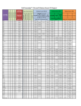
DELL 2900 Server Specifications
for McKesson Pharmacy Systems
Product Name: DELL PE2900 Server
0938307
DELL 2900 Server Specifications for McKesson Pharmacy Systems
Copyright
© 2007 McKesson Corporation. All rights reserved. This documentation is an unpublished
work of McKesson Corporation, which may be used only in accordance with a license
agreement with McKesson Corporation. Any unauthorized use, duplication, or disclosure
is prohibited.
McKesson Corporation assumes no responsibility or liability for any errors or inaccuracies
that may appear in this documentation. Except as permitted by such license, no part of
this publication may be reproduced, stored in a retrieval system, or transmitted, in any
form or by any means, electronic, mechanical, recorded, or otherwise, without the prior
written permission of McKesson Corporation.
Any reference to company names in samples, procedures, or templates are for
demonstration purposes only and are not intended to refer to any actual organization.
Pharmaserv is a registered trademark of McKesson Corporation.
ActiveX, Microsoft, Windows, Windows XP, Windows NT, and Windows Server 2003 are
either registered trademarks or trademarks of Microsoft Corporation in the United States
and/or other countries.
All other trademarks are the property of their respective owners.
Documentation Feedback
We welcome your feedback. If you have comments or suggestions regarding our product
online Help or user documentation (upgrade instructions, release notes, etc.), please email us at [email protected] and type doc tech in the subject line.
Please include the following information with your feedback:
Product and version number (e.g., Pharmaserv Version 3.1.3)
Document name and page numbers
Topic title (for online Help)
Brief description of content error (for example, inaccurate instructions, more detail
needed, grammatical error, inaccurate sample graphic, etc.)
Thank you for taking the time to help us improve our product.
McKesson Pharmacy Systems
Page 2 of 11
DELL 2900 Server Specifications for McKesson Pharmacy Systems
Table of Contents
DELL PE2900 Information .................................................................................................. 4
Dimensions for the DELL 2900 Server..................................................................... 4
Decibel Levels .......................................................................................................... 4
Weight....................................................................................................................... 4
Hardware Part Number............................................................................................. 5
Hardware Configuration............................................................................................ 5
Hardware No Longer Available................................................................................. 6
Front-Panel Features and Indicators .................................................................................. 7
Figure 1-1. Front-Panel Features and Indicators ..................................................... 7
Table 1-2. Front-Panel Components ........................................................................ 8
Hard-Drive Indicator Codes ...................................................................................... 9
Figure 1-2. Hard-Drive Indicators ............................................................................. 9
Table 1-3. Hard-Drive Indicator Patterns for RAID................................................... 9
Back-Panel Features and Indicators................................................................................. 10
Figure 1-3. Back-Panel Features and Indicators.................................................... 10
Connecting External Devices ................................................................................. 11
Power Indicator Codes ................................................................................................ 11
Table 1-4. Redundant Power Supply Indicators..................................................... 11
Figure 1-4. Redundant Power Supply Indicators.................................................... 11
McKesson Pharmacy Systems
Page 3 of 11
DELL 2900 Server Specifications for McKesson Pharmacy Systems
DELL PE2900 Information
Dimensions for the DELL 2900 Server
The DELL 2900 Server has the following approximate dimensions:
•
9 inches wide
•
19 inches high
•
28 inches depth
It is recommended that the server is placed in a well ventilated room with 4 to 6 inches of
space behind the server for cable connections and for heat exhaust/air circulation.
Decibel Levels
You may want to consider the noise level of the DELL server before determining a
placement for your server. The DELL 2900 operates with the following approximate
decibel (dB A) levels:
•
72 dB A at startup* – equivalent to a vacuum cleaner.
•
55 dB A at standing run – equivalent to a large office.
In comparison, the DELL 1800 server operates with the following approximate decibel
levels:
•
64 dB A at startup*
•
51 dB A at standing run
* Startup for either server runs approximately 2 minutes.
Weight
The DELL 2900 Server is associated with the following weights:
•
116 lbs inside the shipping container
•
92 pounds without the shipping container
Use caution whenever you are lifting or moving the server. Always have a helper on hand
before moving the server. The server is shipped with two stabilizing feet and two sets of
rolling casters.
Please consider the proper personnel and tools required when placing a server on an
elevated surface. It is recommended that the casters are not installed when placing the
server on an elevated surface.
McKesson Pharmacy Systems
Page 4 of 11
DELL 2900 Server Specifications for McKesson Pharmacy Systems
Hardware Part Number
PE2900 Premium with 1.60GHz processor and 1066MHz Front-side bus speed is MPS
part number 222-3391
Hardware Configuration
The Dell PE 2900 Premium server has one standard configuration. The technical
specifications are:
•
•
•
•
•
Windows Server 2003 Standard, SP1, Internet Explorer 7
Configurable as member server or Domain Controller
Minimum Pharmaserv build Version 3.2.0.1
Front-side bus speed depends on the part number
4GB 533MHz (4x1GB), Dual Ranked DIMMs
•
•
•
•
•
•
•
•
•
•
933 Watt Redundant 110/220V Power Supplies
48X Combo CD-RW/DVD-ROM
1X8 BACKPLANE,3.5HDD
6X 300GB, SAS 3.5IN Hot Swap Drives
5 1/4 drive enclosure CRU-DATA PORT with SATA drive, 500GB drive
3 additional CRU-DATA Carriers with SATA drives, 500 GB
5 1/4 (2 bays) Dell Flex Bay with two 500 GB SATA drives
Integrated ATI ES1000 controller with 16MB of SDRAM
PERC5/I,X6,INTEGRATED controller with 256MB cache
Dual embedded Broadcom® NetXtreme II™ 5708 Gigabit2 Ethernet NIC with
fail-over and load balancing.
Intel 5000X chipset
1 x8 PCI Express – x8 lane with x8 connector
3 x4 PCI Express – x4 lane with x8 connector
2 x 64-bit/133MHz PCI-X – supports full-height, full-length 3.3v PCI or PCI-X
cards
2 USB 2.0 ports on the front, 4 USB 2.0 ports on the back
1 RS232 serial port on the back
1 VGA connector on the front and one in the back
•
•
•
•
•
•
•
McKesson Pharmacy Systems
Page 5 of 11
DELL 2900 Server Specifications for McKesson Pharmacy Systems
•
•
•
•
•
•
•
•
•
•
•
•
•
•
•
•
•
•
•
Avocent SST-8P PCI MUX and fan out cable
SIIG SATA II PCIE ROHS compliant 2 Port card
TRIPP LITE Serial ATA cable
Keyboard, USB, black
Mechanical two-button mouse, USB, black
Two Stabilizing feet
EDOCS and OPENMANAGE CD kit
Dell OpenManage 5.1.0
DRAC 5
Standard Baseboard Management Controller with IPMI 2.0 support
Two sets of rolling casters P/N TJ201
5U Tower or Rack-mountable chassis
Tower Dimensions (without bezel): 18.85" (47.89cm) H w/feet x 8.92" (22.66cm)
W x 26.55" (67.43cm) D; (including LCD panel).
Tower Weight 49.9 kg (110 lb), maximum configuration
Rack with rack flanges: 8.57" (21.77 cm) H x 17.43" (44.27 cm) W x 26.55"
(67.43 cm) D
Rack Weight 45.36 kg (100 lb), maximum configuration
PESS BASIC NBD TECH SPT,3YR,PE2900
PESS BASIC NBD OS,UNY,INIT,PE2900
PESS BASIC NBD OS,UNY,2YR EXT,PE2900
Hardware No Longer Available
Please note that the following hardware is no longer available in the PE 2900 Premium:
• Parallel ports
• 3.5” diskette drive
• PS2 ports
McKesson Pharmacy Systems
Page 6 of 11
DELL 2900 Server Specifications for McKesson Pharmacy Systems
Front-Panel Features and Indicators
Figure 1-1 shows the controls, indicators, and connectors located behind the optional
rack bezel on the system's front panel. Table 1-2 provides component descriptions.
Refer to the DELL 2900 Premium Server Components Installation for Technical
Support guide for additional information.
Figure 1-1. Front-Panel Features and Indicators
Server is similar to the following picture:
1
2
3
4
5
6
7
8
9
10
McKesson Pharmacy Systems
Page 7 of 11
DELL 2900 Server Specifications for McKesson Pharmacy Systems
Table 1-2. Front-Panel Components
Item Component
Icon
Description
1
Power-on
indicator, power
button
The power-on indicator lights when the system power is on.
The power button controls the DC power supply output to the
system.
NOTE: If you turn off the system using the power button and
the system is running an ACPI-compliant operating system,
the system performs a graceful shutdown before the power is
turned off. If the system is not running an ACPI-compliant
operating system, the power is turned off immediately after
the power button is pressed.
2
NMI button
Used to troubleshoot software and device driver errors when
using certain operating systems. This button can be pressed
using the end of a paper clip.
Use this button only if directed to do so by qualified support
personnel or by the operating system's documentation.
3
System
identification
button
The identification buttons on the front and back panels can be
used to locate a particular system within a rack. When one of
these buttons is pushed, the LCD panel on the front and the
blue system status indicator on the back blink until one of the
buttons is pushed again.
4
LCD panel
Provides system ID, status information, and system error
messages.
The LCD lights during normal system operation. Both the
system management software and the identification buttons
located on the front and back of the system can cause the
LCD to flash blue to identify a particular system.
The LCD lights amber when the system needs attention, and
the LCD panel displays an error code followed by descriptive
text.
NOTE: If the system is connected to AC power and an error
has been detected, the LCD lights amber regardless of
whether the system has been powered on.
5
USB connectors
(2)
Connects USB 2.0-compliant devices to the system.
6
Video connector
Connects a monitor to the system.
7
Optical drive
The CD-ROM drive
8
CRU Drive
Contains a SATA 500 GB Drive
9
Dell Flex Bay
Two SATA 500 GB drives
10
Hard drives
Room for eight hot-pluggable bays for 3.5-inch SAS or SATA
hard drives connected to a 1x8 SAS backplane.
McKesson Pharmacy Systems
Page 8 of 11
DELL 2900 Server Specifications for McKesson Pharmacy Systems
Hard-Drive Indicator Codes
The hard-drive carriers have two indicators—the drive-activity indicator and the drivestatus indicator. See Figure 1-2. In RAID configurations, the drive-status indicator lights
to indicate the status of the drive. In non-RAID configurations, only the drive-activity
indicator lights; the drive-status indicator is off.
Figure 1-2. Hard-Drive Indicators
Hard drive indicator lights are similar to the following picture:
1. drive-status indicator (green and amber)
2. green drive-activity indicator
Table 1-3 lists the drive indicator patterns for RAID hard drives. Different patterns are
displayed as drive events occur in the system. For example, if a hard drive fails, the
"drive failed" pattern displays. After the drive is selected for removal, the "drive being
prepared for removal" pattern displays, followed by the "drive ready for insertion or
removal" pattern. After the replacement drive is installed, the "drive being prepared for
operation" pattern displays, followed by the "drive online" pattern.
Table 1-3. Hard-Drive Indicator Patterns for RAID
Condition
Drive-Status Indicator Pattern
Identify drive/preparing for
removal
Blinks green two times per second
Drive ready for insertion or
removal
Off
Drive predicted failure
Blinks green, amber, and off.
Drive failed
Blinks amber four times per second.
Drive rebuilding
Blinks green slowly.
Drive online
Steady green.
Rebuild aborted
Blinks green three seconds, amber three seconds, and off six
seconds.
McKesson Pharmacy Systems
Page 9 of 11
DELL 2900 Server Specifications for McKesson Pharmacy Systems
Back-Panel Features and Indicators
Figure 1-3 shows the controls, indicators, and connectors located on the system's back
panel.
Refer to the DELL 2900 Premium Server Components Installation for Technical
Support guide for additional information.
Figure 1-3. Back-Panel Features and Indicators
Server is similar to the following picture:
7
8
9
6
5
10
11
4
3
12
2
13
1
NOTE: The MUX will be located in the bottom expansion slot. The SIIG SATA II PCIE
ROHS compliant 2 Port card will be located in the top expansion slot.
1
serial connector
2
video connector
3
USB connectors (4)
4
NIC1 connector
5
NIC2 connector
6
remote access
connector (optional)
7
expansion-card slots
(6)
8
system status indicator
9
system identification
button
10 system status
indicator connector
11 power supply 2 (not
shown in this picture)
12 power supply status
indicators
13 power supply 1
McKesson Pharmacy Systems
Page 10 of 11
DELL 2900 Server Specifications for McKesson Pharmacy Systems
Connecting External Devices
When connecting external devices to your system, follow these guidelines:
•
Most devices must be connected to a specific connector and device drivers must
be installed before the device operates properly. (Device drivers are normally
included with your operating system software or with the device itself.) See the
documentation that accompanied the device for specific installation and
configuration instructions.
•
Always attach an external device while your system and the device are turned
off. Next, turn on any external devices before turning on the system (unless the
documentation for the device specifies otherwise).
•
USB devices will sometimes stall the system boot up when the BIOS is posting.
Power Indicator Codes
The power button on the front panel controls the power input to the system's power
supplies. The power indicator lights green when the system is on.
The indicators on the optional redundant power supplies show whether power is present
or whether a power fault has occurred (see Table 1-4 and Figure 1-4).
Table 1-4. Redundant Power Supply Indicators
Indicator
Function
Power supply status Green indicates that the power supply is operational.
Power supply fault
Amber indicates a problem with the power supply.
AC line status
Green indicates that a valid AC source is connected to the power supply.
Figure 1-4. Redundant Power Supply Indicators
Power indicator codes are similar to the following picture:
1. power supply status
2. power supply fault
3. AC line status
McKesson Pharmacy Systems
Page 11 of 11