1
SRlOl Series 2 Audio Console
OPERATION AND SERVICE MANUAL
Manufactured by
SHURE BROTHERS INC.
222 Hartrey Avenue
Evanston, Illinois 60204 U.S.A.
Copyright 1979, Shure Brothers Inc.
27A1171 (SD) (95E652)
Printed in U.S.A.
SR101 Series 2 Audio Console
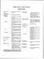
SPECIFICATIONS
Equipment Type
. . . . . All silicon transistor mixerlpreamplifier
Number of
lnput Channels . . . . . . 8
Power Output . . . . . . . . . +19 dBm (program line level)
Voltage Gain*
Program . . . .
.73 k 3 dB MIC input to LlNE
LEVEL out
50 k 3 dB AUX input to LlNE
LEVEL out
23 t 3 d ~MIC input to MIC LEVEL
out
Monitor . . . . . . . . . .78 1 3 dB MIC input via PROGRAM MONITOR to LlNE
LEVEL out
65 k 3 dB MIC input via PROGRAM MONITOR to PHONES
out
87 2 3 dB MIC input via one channel MONITOR to LINE LEVEL
out
Link . . . . . . . . . . . . .38 _t3 dB MIC input to LlNK OUT
(with 600-ohm termination)
30 2 2 dB LlNK IN to LlNE LEVEL
out
Accessory . . . . . . . .48 t 2 dB MIC input to ACCESSORY output (via pins 1-8lINPUTS)
43 i.3 dB MIC inputs to ACCESSORY output (via pin 91PROGRAM)
... 1
3 dB, 20 Hz-20 kHz (150-ohm
source; 600-ohm load)
lnput Sensitivity . . . . . . . 0.4 mV max. for f 4 dBm program
output
Distortion . . . . . . . . . . . . THD less than 1% at +12 dBm,
30 Hz -20 kHz; IM distortion
less than 1% at t 1 2 dBm
Noise
(300 Hz-20 kHz) . . . . . - 128 dBV(equiva1ent input noise
at full gain)
- 78 dBm output noise (MASTER
Volume Control down)
- 53 dBm output noise (one
channel Volume Control and
MASTER Volume Control up)
Frequency Response
'Measurement conditions: MIC input through 150 ohms, AUX input through 33
kilohms LlNK IN through 600 o h m s PROGRAM LlNE LEVEL and MONITOR
LlNE LEVEL terminated In 600 O ~ ~ ~ . ' P R O G RMIC
A MLEVEL terminated in 150
ohms. MONITOR PHONES terminated in 8 ohms: MASTER Volume. Channel
~olur;le and MONITOR Controls full up; all other controls and switches 0 or off.
Hum and Noise
(20 Hz-20 kHz) . . . . . . . - 125 dBV (equivalent input hum
and noise at full gain)
- 68 dBm output noise (MASTER
Volume Control down)
- 50 dBm output noise (one
channel Volume Control and
MASTER Volume Control up)
Signal to Noise Ratio
(20 Hz-20 kHz) . . . . .Typically 81 dB at maximum output with one channel Volume
Control and MASTER Volume
Control at 10 (approximately
60 dB gain)
lnput Attenuation . . . . . .O-30 dB (10 dB steps)
Input Clipping Level
at kHz:
MIC Input . . . . . . . ,315 mV (INPUT ATTEN at 0;
Volume at 2)
17.5 mV (INPUT ATTEN at 0;
Volume at 14)
10V (INPUT ATTEN at -30;
Volume at 2)
0.56V (INPUT ATTEN at -30;
Volume at 14)
AUX Input . . . . . . . .3.15V (INPUT ATTEN at 0;
Volume at 2)
0.18V (INPUT ATTEN at 0;
Volume at 14)
IOOV (INPUT ATTEN at -30;
Volume at 2)
5.6V (INPUT ATTEN at -30;
Volume at 14)
Input Common
Mode Rejection
. .. .
LOW-~requency
Equalization . . . . . .
Hig h-Frequency
Equalization . . . . . .
Ch.
Ch.
Ch.
Ch.
Ch.
Ch.
Ch.
Ch.
100 dB min. at 100 Hz (balanced
inputs)
-;I3 dB at 100 Hz with respect to
0 (flat) setting
k 1 2 dB at 10 kHz with respect to
0 (flat) setting
SR101 Series 2 Audio Console
SPECIFICATIONS
Feedback Filter
Frequencies . . . . . . . . I 3 0 Hz; 800 Hz; 2 kHz; 5 kHz
Tone Oscillator . . . . . . . . 1 kHz; less than 1 % distortion;
variable level
lnput Impedance
at 1 kHz:
Microphone . . . . . .1.2 kilohms balanced (for use
with 25- to 600-ohm' microAuxiliary
phones)
(Channels 7
and 8). . . . . . . . . . I 7 0 kilohms unbalanced
Link Input . . . . . . . .35 kilohms unbalanced
Output Impedances:
Program . . . . . . . . . Balanced line level: 120 ohms
actual (for use with 600-ohm
lines)
Microphone level: 0.5 ohms actual
(for use with 25- to 600-ohm inputs)
Monitor
. . . . . . . . ..Unbalanced
line level: 600 ohms
actual (for use with 600-ohm or
high-impedance phones, or
600-ohm lines)
Headphones: 3 ohms actual (for
use with 4- to 16-ohm headphones)
ACCESSORY AUX LEVEL (unbalanced) pins 1-811NPUTS: 33
ohms actual (for use with 3kilohm or greater loads); pin 91
PROGRAM: 600 ohms actual
Link Output
Monitor System
. . . . . . .600 ohms (actual)
. . . . . . .Headphone andlor
600-ohm line
output; individual and mixed
channel select or program; preand post-link monitoring
Reverberation
System . . . . . . . . . . . . .Spring type with individual channel intensity controls and highand low-frequency equalization
Link Jack System
. . . . . . External signal conditioning outputlinput; high-level auxiliary
amplifier and tape recorder
signal output; multiple Console
connection (mix bus); remote
master volume control
VU Meter Calibration . . . $4 dBm (1.23 Vrms) at 1 kHz to
600-ohm load (METER SENSITlVlTY ~ o n t r o l ' i nCAL position)
[22 dB-range METER SENSITIVITY Control in full clockwise
position provides 0 VU reading
of -18 dBm (0.1 Vrms) on 600ohm load]
Phasing (polarity). . . . . .AUX LEVEL input and LINK IN
tips and pin 3 of INPUT connectors in phase with pin 9 of
ACCESSORY OUTPUT; tips of
LlNK OUT, PROGRAM LlNE
LEVEL, and MONITOR LlNE
LEVEL outputs; tip of PHONES
jack; and pin 3 of PROGRAM
LlNE and MIC LEVEL outputs.
(PHASE Switch in 0" position.)
Pins 1-8 of ACCESSORY OUTPUT out of phase with the
above.
Phase Switch . . . . . . . . . Output polarity-reversing switch
(0°, 180°) (reverses phase of all
program outputs)
30 Vdc Bus . . . . . . . . . . .Pin 10 on ACCESSORY AUX
LEVEL connector is regulated
5 supply; pin 11 is
+30 ~ 3 . Vdc
ground (earth). May be used to
power accessories with up to
50 mA.
Operating Voltage . . . . .90-132 Vac, 50160 Hz (SR101)
90-132, 180-250 Vac, 50160 Hz
(SR101-2E)
Power Consumption . . . 20 watts max. (Console only). 500
watts max. (SWITCHED A. C.
receptacle)
Temperature Range:
Operating . . . . . . . . . . -7' to 54OC (20' to 130°F)
Storage . . . . . . . . . . . . -29' to 71°C (-20' to 160°F)
Dimensions . . . . . . . . . . .311 mm x 483 mm x 162 mm
(121/'" H x 19" W x 6%'' D)
Installation . . . . . . . . . . . Equipped for standard 19" rack
mounting (12%" height); may
b e operated i n accessory
AlOlA Carrying Case or in custom control center
Weight . . . . . . . . . . . . . . .22 Ib (10 kg)
Finish . . . . . . . . . . . . . . . . Matte black, with beige write-on
trim strip
Certifications . . . . . . . . . Listed by Underwriters' Laboratories, Inc.; listed by Canadian
Standards Association as certified (SRIOI only)
iii
SR101 Series 2 Audio Console
TABLE OF CONTENTS
Section
Page
SPECIFICATIONS . . . . . . . . . . . . . . . . . . . . . . . . . . . . . . ii
DESCRIPTION . . . . . . . . . . . . . . . . . . . . . . . . . . . . . . . . . 1
OPERATING INSTRUCTIONS
Functional Identification . . . . . . . . . . . . . . . . . . . . . . . 3
General Operating Instructions . . . . . . . . . . . . . . . . . 3
Mounting and Ventilation . . . . . . . . . . . . . . . . . . . . . . 4
Power Supply . . . . . . . . . . . . . . . . . . . . . . . . . . . . . . . . 5
Functional Circuit Description . . . . . . . . . . . . . . . . . . 5
Input Channels . . . . . . . . . . . . . . . . . . . . . . . . . . . . . . 7
Source Cuing . . . . . . . . . . . . . . . . . . . . . . . . . . . . . . . . 7
Reverberation . . . . . . . . . . . . . . . . . . . . . . . . . . . . . . . . 7
Monitor System . . . . . . . . . . . . . . . . . . . . . . . . . . . . . . 8
Monitor Mixer System . . . . . . . . . . . . . . . . . . . . . . . . . 8
Program Mix Amplifier . . . . . . . . . . . . . . . . . . . . . . . 9
Link Jacks . . . . . . . . . . . . . . . . . . . . . . . . . . . . . . . . . . 9
Feedback Filters . . . . . . . . . . . . . . . . . . . . . . . . . . . . . 9
Program Output . . . . . . . . . . . . . . . . . . . . . . . . . . . . . 9
VU Meter Circuit . . . . . . . . . . . . . . . . . . . . . . . . . . . . 10
Tone Oscillator . . . . . . . . . . . . . . . . . . . . . . . . . . . . . .10
Basic Operating Hints . . . . . . . . . . . . . . . . . . . . . . . . 11
SPECIAL OPERATING INSTRUCTIONS
High-Impedance Microphones . . . . . . . . . . . . . . . . . 11
Musical Instruments . . . . . . . . . . . . . . . . . . . . . . . . . . 11
Tape Recording . . . . . . . . . . . . . . . . . . . . . . . . . . . . . 12
Record Playback . . . . . . . . . . . . . . . . . . . . . . . . . . . . . 12
Tape Playback . . . . . . . . . . . . . . . . . . . . . . . . . . . . . . . 12
Talkback Circuit . . . . . . . . . . . . . . . . . . . . . . . . . . . . . . 13
Additional Mixer Inputs . . . . . . . . . . . . . . . . . . . . . . . . 13
Section
Page
Additional Console Inputs (Two Consoles) . . . . . . . . 14
Redundant Console Set-up (Two Consoles) . . . . . . . 15
Stereo Operation . . . . . . . . . . . . . . . . . . . . . . . . . . . . 16
Remote Volume Control . . . . . . . . . . . . . . . . . . . . . . . 17
Telephone Line Surge Protection . . . . . . . . . . . . . . 17
SERVICE INSTRUCTIONS
Console Service . . . . . . . . . . . . . . . . . . . . . . . . . . . . . . 18
Replacement Parts . . . . . . . . . . . . . . . . . . . . . . . . . . . . 18
Fuse Replacement . . . . . . . . . . . . . . . . . . . . . . . . . . . . 18
Knob Replacement . . . . . . . . . . . . . . . . . . . . . . . . . . . 18
ServiceAccess . . . . . . . . . . . . . . . . . . . . . . . . . . . . . . . 18
Lamp Replacement . . . . . . . . . . . . . . . . . . . . . . . . . . . 18
Reverberation Assembly . . . . . . . . . . . . . . . . . . . . . . . 18
Board Removal . . . . . . . . . . . . . . . . . . . . . . . . . . . . . . . 18
VU Meter Removal . . . . . . . . . . . . . . . . . . . . . . . . . . . .20
VU Meter Calibration . . . . . . . . . . . . . . . . . . . . . . . . . . 20
Volume Control Assembly . . . . . . . . . . . . . . . . . . . . . 20
Parts Removal . . . . . . . . . . . . . . . . . . . . . . . . . . . . . . . 21
Transistor and Diode Removal . . . . . . . . . . . . . . . . . 22
Transistor and Diode Checking . . . . . . . . . . . . . . . . . 22
Service Illustrations . . . . . . . . . . . . . . . . . . . . . . . . . . . 22
Optional Accessories . . . . . . . . . . . . . . . . . . . . . . . . . . 22
Guarantee . . . . . . . . . . . . . . . . . . . . . . . . . . . . . . . . . . . 22
Shipping Instructions . . . . . . . . . . . . . . . . . . . . . . . . . 22
PARTS LIST . . . . . . . . . . . . . . . . . . . . . . . . . . . . . . . . . . . 23
CONDENSED OPERATING INSTRUCTIONS . . . . . . . . 47
ARCHITECTS' AND ENGINEERS'
SPECIFICATIONS . . . . . . . . . . . . . . . . . . . . . . . . . . . . 47
SR101 Series 2 Audio Console
LlST OF ILLUSTRATIONS
Figure
1
2
3
4
5
6
7
8
9
10
11
12
13
14
15
Page
SR101 Audio Console Front Panel . . . . . . . . . . . 2
SR101 Audio Console Rear Panel . . . . . . . . . . . . 2
SRlO1 Audio Console Dimensional
Outline Drawing . . . . . . . . . . . . . . . . . . . . . . . . . 5
SR101 Audio Console Block Diagram . . . . . . . . 6
Monitor Mixer Applications . . . . . . . . . . . . . . . . 9
Tone Oscillator Applications . . . . . . . . . . . . . . . 10
Preamplifier-Console Connnections . . . . . . . . . 11
Tape Recording . . . . . . . . . . . . . . . . . . . . . . . . . .12
Record Playback . . . . . . . . . . . . . . . . . . . . . . . . 13
Talkbackcircuit . . . . . . . . . . . . . . . . . . . . . . . . . . 13
Carbon Microphone Power Supply . . . . . . . . . . 13
Additional Mixer Inputs . . . . . . . . . . . . . . . . . . . . 14
Additional Inputs: Two Consoles . . . . . . . . . . 15
Redundant Consoles . . . . . . . . . . . . . . . . . . . . . . 16
Stereo Tape Recording . . . . . . . . . . . . . . . . . . . 17
Figure
16
17
18
19
20
21
22
23
24
25
26
27
28
29
30
31
32
Page
Remote Volume Control . . . . . . . . . . . . . . . . . . . 17
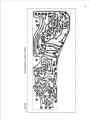
Printed Circuit Board and Parts Location . . . . . 19
Volume Control Assembly . . . . . . . . . . . . . . . . . . 21
Board 1: Preamplifier . . . . . . . . . . . . . . . . . . . . . 33
Board 2A: Channel Equalizer . . . . . . . . . . . . . . 34
Board 28: Reverb Equalizer . . . . . . . . . . . . . . . 34
Board 3: Program Mix Amplifier . . . . . . . . . . . . . 35
Board 4: Reverb Mix Amplifier . . . . . . . . . . . . . . 35
Board 5: Program Output . . . . . . . . . . . . . . . . . . 36
Board 6: Feedback Filters . . . . . . . . . . . . . . . . . 37
Board 7: Reverb Spring Amplifier . . . . . . . . . . . 37
Board 8: Monitor . . . . . . . . . . . . . . . . . . . . . . . . . 38
Board 9: Power Supply . . . . . . . . . . . . . . . . . . . . 38
Board 0: Program Mute . . . . . . . . . . . . . . . . . . . . 39
Transistor Lead Codes . . . . . . . . . . . . . . . . . . . . 41
SR101-2E Power Supply . . . . . . . . . . . . . . . . . . . 42
Circuit Diagram . . . . . . . . . . . . . . . . . . . . . . . . 44-45
SRIOI Series 2 Audio Console
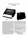
DESCRIPTION
(Shown in A I O I A
Carrying Case w i t h
A l O l B Panel Lamp)
The Shure Model SR101 series 2 Audio Console is a
solid-state, eight-channel microphone mixer-preamplifier
that enables the operator to mix as many as eight microphones with individual control over volume, reverberation,
and high- and low-frequency equalization. The Series 2
Consoles have rear-panel provisions for connection to up
to eight Shure SR110 Professional Monitor Mixers. The
SR110 is a self-contained, eight-channel, line level mixer
designed to provide a separate stage monitor mix that
follows the program mix levels. In addition, it may be used
in multi-track recording as a recording mix panel. The Console has two outputs: a program output and a monitor output. In addition, channels 7 and 8 contain switch-selectable
input connectors for .use with auxiliary high-level sources
or high-impedance microphones. Master volume controls
regulate program and monitor outputs. Program and monitor switches permit the operator to select the input signals
to be routed to each of the two outputs.
The program output has both a 600-ohm, balanced, line
level output and a low-impedance, balanced, microphone
output. The monitor has two outputs: a 600-ohm unbalanced output and an 8-ohm balanced headphone output.
Four switch-selectable feedback filters are included in the
program output, and a pair of link jacks facilitate connection to an additional audio console, mixer, or external
equipment such as compressors, limiters or equalizers.
The Console contains a VU meter with adjustable sensitivity to indicate program output level. A built-in 1 kHz
tone oscillator facilitates synchronization of all meters in
the system. An optional panel lamp accessory may be connected to the front panel lamp connector for illumination
of controls. Accessory equipment drawing up to 500 watts
may be connected to the rear-panel switched ac receptacle.
A front-panel trim strip provides space for pencilled notations.
The regulated power supply is designed to operate over
a wide range of input voltages, permitting the use of extremely long ac extension cables without performance
degradation.
The solid-state components in the SR101 Audio Console are protected against damage as a possible result
of open-circuit or short-circuit conditions on the inputs
or outputs. All components are conservatively rated and
are operated well within their respective ratings to assure
long life and trouble-free performance.
The Console is supplied with rack-mounting screws and
spare fuses (the SRlOI-2E comes with a detachable line
cord).
The Console is Underwriters' Laboratories, Inc., listed,
and is listed by the Canadian Standards Association as
certified (SRI 01 only).
The following accessories are specifically designed for
use with the SRlOl Series 2 Audio Console:
A l O l A Carrying Case
A101 B Panel Lamp Accessory
SR110 Professional Monitor Mixer
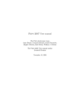
FIGURE 1. SRlOl SERIES 2 AUDIO CONSOLE FRONT PANEL
25
26
29
30
34
32
36
-
(SR101 2E Only)
35
37
-
(SR101 2E Only)
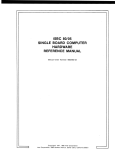
FIGURE 2. SRlOl SERIES 2 AUDIO CONSOLE REAR PANEL
2
33
SR101 Series 2 Audio Console
OPERATING INSTRUCTIONS
FUNCTIONAL IDENTIFICATION (Refer to Figures 1 and
2, Page 2.)
NOTE: All push-button switches are "on" when in (depressed) and "off" when out (released). Input attenuator
switches are calibrated in decibels; all other front panel
controls are numbered for reference only.
1. lndividual Channel Volume Slide Controls (Eight) Control volume and input clipping level of each channel separately.
2. REVERB INTENSITY Rotary Controls (Eight) - Control reverb level for each channel.
3. Master REVERB Push-Button Switch -Turns on (or
off) amount of reverb preset by channel REVERB INTENSITY controls.
4. REVERB FREQuency EQualizer-LOWRotary Control Adjusts low-frequency reverb signal equalization.
5. lndividual Channel FREQuency EQualizer-LOW Rotary
Controls (Eight) - Adjust low-frequency signal equalization for each channel.
6. REVERB FREQuency EQualizer-Hlgh Rotary Control Adjusts high-frequency reverb signal equalization.
7. lndividual Channel FREQuency EQualization-Hlgh Rotary Control (Eight) - Adjusts high-frequency signal
equalization for each channel.
8. PHONES Output Jack - Provides for connection of
stereo or monophonic headphones for monitoring.
9. Panel LAMP Accessory Connector - Provides connection for optional panel lamp accessory to illuminate front panel.
10. MONITOR Level Rotary Control - Controls volume
level to PHONES Jack (8) and MONITOR OUTPUT/
LlNE LEVEL Jack (30).
11. PROGRAM MONITOR Push-Button Switch - Connects total program output (all channels and reverb)
to PHONES Jack (8) and MONITOR OUTPUT/LINE
LEVEL Jack (30).
12. lndividual Channel MONITOR Push-Button Switches
(Eight) - Connect individual channel outputs (without reverb) to PHONES Jack (8) and MONITOR OUTPUT/LINE LEVEL Jack (30) when PROGRAM MONITOR Switch (11) is off.
13. lndividual Channel PROGRAM Push-Button Switches
(Eight) - Connect individual channel inputs to program output.
14. lndividual Channel INPUT ATTENuator Rotary
Switches (Eight) - Provide choice of input signal attenuation for each channel. Dual switches on channels 7 and 8 also select low-impedance (MIC) or highimpedance (AUX) input connections.
15. FEEDBACK FILTERS Push-Button Switches (Four) Provide for elimination of acoustic feedback in four
most probable audio frequency ranges.
16. TONE Oscillator LEVEL SwitchIRotary Control Turns on and adjusts level of 1 kHz tone generated
internally for set-up purposes.
17. True VU Meter - Indicates volume level of program
output. (Meets all current standards for VU Meters).
18. METER SENSITIVITY Rotary Control - Adjusts VU
meter sensitivity for wide ranges of program level
indication.
19. POWER ON-OFF Toggle Switch - Applies ac power
to power supply and SWITCHED A.C. Receptacle (23).
20. MASTER Volume Slide Control - Adjusts level of total
program output.
21. Ac Grounded Line Cord - Connects ac power source
to Console power supply (SRlO1 only).
22. 3AG-3/16A SLO-BLO Ac Fuse - Protects Console ac
input line against overload (SRlOl only).
23. SWITCHED A. C. Grounded Receptacle - Provides up
to 500 watts of switched ac power to accessory equipment iSR101 only).
24. PROGRAM OUTPUTSIMICrophone LEVEL 3-Pin Connector - Provides low-impedance microphone-level
program output.
25. PROGRAM OUTPUTS/LINE LEVEL Phone Jacks
(Two) - Provide balanced or unbalanced output connections to power amplifier.
26. PROGRAM OUTPUTS/PHASE Slide Switch - Reverses phase (polarity) of LlNE LEVEL and MIC LEVEL
program outputs with respect to inputs.
27. PROGRAM OUTPUTSILINE LEVEL 3-Pin Connector
- Provides balanced output connection to power
amplifier.
28. LlNK IN Phone Jack- Provides input connection for
external equipment (compressor, limiter, equalizer,
etc.).
29. MONITOR OUTPUTIPOST LINK-PRE L l N K Slide
Switch - Selects program monitoring either before or
after external equipment connection to LlNK Jacks (28,
31).
30. MONITOR OUTPUTILINE LEVEL Phone Jack - Provides monitor output connection to power amplifier.
31. LlNK OUT Phone Jack - Provides output connection
for external equipment, or mix bus to add Consoles.
32. INPUTS/AUX. LEVEL Phone Jacks (Two) - Provide
for connection of high-impedance sources to channel
7 or 8 inputs.
33. INPUTS/ MICROPHONE LEVEL 3-Pin Jacks (Eight) Provide for balanced connection of low-impedance
sources to channels 1 through 8 inputs.
34. ACCESSORY AUX LEVEL 1I-Pin Connector-Provides
output connection to Shure SR110 Monitor Mixer.
35. AC (MAINS) POWER 3-Pin Connector-Connects
ac
power cable to Console power supply (SRlOl-2E only).
36. VOLTAGE SELECTOR Slide Switch-Selects
operating voltage range of 90 to 132 or 180 to 250 Vac,
50/60 Hz (SRIOI-2E only).
37. 180-250V 0.1AT/90-132V 0.2AT Ac Fuse-Protects
Console ac input line against overload (SR101-2E
only).
GENERAL OPERATING INSTRUCTIONS
WARNING
Voltages in this equipment are hazardous to life. Make
all input and output connections with ac power disconnected. Refer servicing to qualified service personnel.
1. Using hardware provided, install Console securely in
standard 19" (483 mm) rack or optional AlOIA Carrying Case prior to making electrical connections. For
custom installations, see mounting template supplied
with Console. If desired, connect A l O l B Panel Lamp
Accessory to LAMP Connector (9).
3
2. Set all front-panel switches to off (out) and all controls to 0. Set rear-panel PHASE Switch (26) to 0'.
3. Connect desired PROGRAM OUTPUT/LINE LEVEL
Connector (25,27) to power amplifier input connecting cable. (NOTE: Shure SR105 Power Amplifiers
are supplied with audio connecting cables.) If Console
output is to be fed to another mixer or tape recorder
microphone input, use PROGRAM OUTPUT/MIC
LEVEL Connector (24). If desired, connect monophonic or stereo headphones to front-panel PHONES
Jack (8). Connect speakers to power amplifier.
4. Connect one or more low-impedance microphones to
rear-panel INPUTS/MICROPHONE LEVEL Connector
(33). Any high-quality dynamic, ribbon or condenser
low-impedance microphone may be used. Connect
high-impedance microphones or auxiliary high-level
sources to INPUTS/AUX. LEVEL Connectors (32) in
channels 7 or 8 only. If AUX. LEVEL Connectors are
used, set corresponding front-panel MIC/AUX (INPUT
ATTEN) Switch (14) to AUX.
5. If external signal-processing equipment such as an
equalizer, compressor or limiter is to be used, connect Console LlNK OUT Connector (31) to external
equipment input and Console LlNK IN Connector (28)
to external equipment output. (See Link Jacks, Page
8, for detailed information.)
6. SR101: Connect ac line cord (21) to grounded 90- to
132-volt, 50/60 Hz ac source.
Line cord is a 2.44m (8-ft.), 3-conductor cord with
3-pin grounding plug. If extension cords are required,
use high-quality, rubber-jacketed cable with 18 gauge
or larger wire.
SRlOl-2E: Obtain suitable &pin male ac connector
and attach to line cord: brown lead to "hot" or "live"
terminal, blue lead to neutral terminal, and green/
yellow lead to ground or earth terminal. (Connector
should be installed by qualified service personnel.)
Select proper operating voltage (90-132V or 180250V) using VOLTAGE SELECTOR Switch (36). Note
that switch positions are marked 115 and 220 volts.
Make certain proper fuse is installed in fuseholder
(37): O.1AT with switch set to 220, or 0.2AT with
switch set to 115. Insert female end of line cord into
chassis power connector (35) and connect male plug
to 3-wire grounded ac power receptacle providing
proper operating voltage.
7. Turn on front-panel POWER Switch (19) and allow
one to two minutes warmup time. This warmup time
allows the supply voltages to stabilize and capacitors
to charge to provide optimum performance. Depress
PROGRAM Switch (13) for channel to be used. (IMPORTANT: No program output will result if this switch
is not depressed!) Set INPUT ATTEN Control (14) for
that channel initially to 0 for normal or PA use, to -10
for instrumental music, or to -20 or -30 for "hard"
rock music. For AUX. INPUT sources (channels 7 and
8), set INPUT ATTEN Control initially to -20 or -30.
8. Set MASTER Volume Control (20) to 7. Set METER
SENSITIVITY Control (18) to CAL position. Have someone sing or talk into microphone and raise channel
Volume Control (1) to achieve desired sound level. If
VU Meter (17) reads too low at proper sound level, increase METER SENSITIVITY Control until normal meter movement - operation in black area of scale with
occasional peak excursions into red area - is ob-
9.
10.
11.
12.
tained. If meter still reads low, reduce power amplifier
volume level and increase channel volume level. For
single microphone set-up, if meter indicates excessively high level ("pinning" or "pegging" needle),
decrease channel Volume Control to obtain good
meter reading and increase power amplifier volume
level or input sensitivity to obtain proper sound level.
In multiple microphone set-up, it may be necessary to
decrease MASTER Volume Control in order to maintain channel Volume Control setting. Ideally, channel
Volume Control should remain approximately at midrange (7-9) to facilitate increases or decreases in control setting due to program change; INPUT ATTEN
Control (14) adjustment will aid in maintaining this setting. If feedback occurs below desired sound level,
consult section on Feedback Filters (Page 8).
Set HI and LO FREQ EQ Controls (7,5) for channel in
use. Vertical position (0) indicates "flat" frequency response. Clockwise (+) settings increase high-frequency (treble) or low-frequency (bass) equalization
and counterclockwise (-)
settings decrease frequency equalization. Note that these controls also
affect feedback; readjustment of Feedback Filters (15)
may be necessary.
If reverberation is desired, depress REVERB Switch
(3) and adjust REVERB INTENSITY Control (2) to
desired level for channel in use. Recommended settings are: speech - 0, vocals - 3-6, instruments 5-10. Adjust HI and LO REVERB FREQ EQ Controls
(6,4) for desired frequency equalization.
To monitor channel in use, depress MONITOR Switch
(12) for that channel. Monitor output is available at
front-panel PHONES Jack (8) and rear-panel MONITOR OUTPUT/LINE LEVEL Jack (30). Adjust MONITOR Control (10) for comfortable listening level. Note
that any or all channels may be monitored whether or
not PROGRAM Switch (13) for that channel is depressed; merely depress MONITOR Switch for desired
channel. When total program output monitoring is desired, depress PROGRAM MONITOR Switch (11). Note
too that only those channels with PROGRAM Switch
(13) depressed will be heard while monitoring with
PROGRAM MONITOR Switch depressed.
NOTE: During temporary shutdown (break, intermission), it is not necessary to turn off Console power. It
is designed to operate continuously, and optimum performance is maintained after internal voltages are allowed to stabilize. Also, do not turn off all microphones.
Leave the master or announcer's microphone on (PROGRAM Switch depressed) so that i f the Console is left
unattended, announcements may be made, and the
Console operator will be alerted that the next performance is about to begin.
MOUNTING AND VENTILATION
The Shure SR101 Audio Console may be operated in a
standard 19" (483 mm) audio equipment rack, in a Shure
AlOlA Carrying Case, or custom-mounted in a table- or
desk-type control center. Four rack-mounting screws are
provided with the Console. These screws may also be used
if the Console is to be custom-mounted in a metal-top control center.
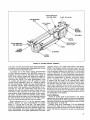
A custom-mounting template is supplied with the Console. Cutting dimensions and drill hole locations are given,
as are clearances for insertion and ventilation. The dimen-
operation) or a 0.2-ampere Slo-Blo fuse (for 90- to 132-volt
operation). Wired-in 3/10- and 1-ampere fuses protect the
ac line and power transformer 5.6-volt secondary winding,
respectively.
sions given should be followed to provide adequate cable
clearance (see Figure 3, Page 5).
In either rack- or custom-mounted installations, consider
rear-panel access before installation is made. Although
most installations will not require frequent access, it should
be remembered that input and output changes, and some
switch movements, will necessitate rear-panel access. Rear
panels are most easily reached in standard audio racks or
in custom installations having bottom access, such as an
open desk or a lower control center access panel.
,
.
NOTE: CLEARANCE DIMENSIONS
SHOWN. SEE MOUNTING
TEMPLATE.
I
I
I
I
I
-
* NOT INCLUDING CONNECTOR/CABLE CLEARANCE DEPTH.
--
-
I
FIGURE 3. SRlOl AUDIO CONSOLE
DIMENSIONAL OUTLINE DRAWING
POWER SUPPLY
SR101: The SR101 regulated power supply is designed to
operate from 90 to 132 volts ac, 50/60 Hz without adjustments, allowing the Console to meet all specifications over
this wide range of ac input voltages. A three-conductor,
grounded line cord (21) supplies ac power to the Console
through the front-panel POWER ON-OFF Switch (19). The
Console consumes 20 watts maximum (0.2 amperes) and
the ac line input is protected by a 3/16-ampere slo-blo fuse
(22) and a wired-in 3/10-ampere slo-blo fuse in series. A
wired-in 1-ampere slo-blo fuse protects the 5.6-volt secondary winding (indicator lamp) of the power transformer.
CAUTION
These fuses should not be replaced with any
other size or type of fuse.
Accessory equipment may be connected to the rearpanel SWITCHED A.C. Receptacle (23). The accessory
equipment may consume up to 500 watts maximum, which
provides for use with high-power amplifiers such as the
Shure SR105. Note that the receptacle is switched but not
fused; all accessory equipment used with the Console
should contain its own fuse.
SR101-2E: The SR101-2E regulated power supply is designed to operate from either 90 to 132 volts ac or 180 to
250 volts ac, 50/60 Hz, as selected by the rear-panel VOLTAGE SELECTOR Switch (36). A three-conductor, grounded
line cord supplies ac power to the Console through the
front-panel POWER ON-OFF Switch (19). The SR101-2E
line cord does not have a connector on the power source
end of the cord. Obtain a suitable three-pin male ac connector and install it on the line cord: brown to "hot" or
"live" terminal, blue lead to neutral terminal, and green/
yellow lead to ground or earth terminal. (Connector should
be installed by qualified service personnel.) The ac line is
protected by a 0.1-ampere Slo-Blo fuse (for 180- to 250-volt
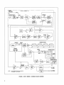
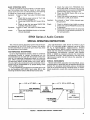
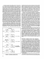
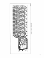
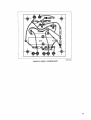
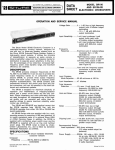
FUNCTIONAL CIRCUIT DESCRIPTION
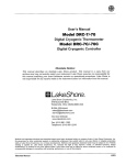
(See Figure 4, Page 6)
Each 3-pin professional audio input Microphone Connector (33) feeds its own low-impedance lnput Transformer,
which provides a gain increase of 23 dB. Channels 7 and 8
also contain switchable AUX LEVEL phone jacks (32) which
accept high-impedance microphones or other inputs. The
lnput Transformers (and, on channels 7 and 8, the AUXMIC Switch) are fed to 0-30 dB INPUT ATTEN Controls (14)
and then to the Preamplifier, which provides a A 6 to $30
dB gain increase. The amount of gain provided by the Preamplifier (6 to 30 dB) is controlled by the Channel Volume
Control ( I ) , providing an increase in input clipping level as
gain is reduced. The Preamplifier circuits contain the individual Channel Volume Controls and feed the individual
Channel Equalizer (HI and LO FREQ EQ) Controls (73)
which decrease the signal approximately 2 dB when set to
the 0, or "flat," setting.
The Equalizer outputs go to the Program and Monitor
circuits, and to the ACCESSORY AUX LEVEL Connector
(34) for interconnection with SR110 Monitor Mixers. The
Channel Equalizer outputs going to the Program circuits
go first to the individual channel PROGRAM Switch (13),
and subsequently to the Reverb circuits and individual
channel REVERB INTENSITY Controls (2). When reverb is
not used, the REVERB INTENSITY Control is set to 0, and
the channel output is sent directly to the Program Mix
Amplifier. When reverb is employed - REVERB Switch (3)
depressed - the REVERB INTENSITY Control feeds the
Reverb Intensity Mix Amplifier, Reverb Equalizer, Reverb
Driver and Differential Amplifiers, Reverb Output Mix Amplifier, and then into the Program Mix Amplifier. Note that as
the control is increased the amount of non-reverb ("dry")
signal sent to the Program Mix Amplifier is reduced, while
the signal sent to the Reverb lntensity Mix Amplifier is
increased.
The Channel Equalizer output to the Monitor input, controlled for each channel by a MONITOR Switch (12), is fed
to the Monitor Mix Amplifier, which changes the input by
+3 to -13 dB. The Amplifier output goes to the PROGRAM
MONITOR Switch (1I ) , where it may be selected to continue
through the MONITOR Level Control (lo), +40 dB Monitor
Amplifier, and to the rear-panel MONITOR OUTPUT/LINE
LEVEL jack (30) and front-panel PHONES jack (8).
The Program Mix Amplifier goes to both the PRE LlNK
side of the POST LINK/PRE LlNK Switch (29) for routing to
the Monitor circuits, and through a 560-ohm resistor to the
LlNK jacks (28,31). When accessory equipment is not connected to the LlNK jacks, the jacks are bypassed and the
program signal is fed to the POST LlNK side of the POST
LINK/PRE LINK Switch for monitoring, and to the MASTER
Volume Control (20). Note that the PRE LINK/POST LlNK
Switch output to the Monitor circuits is also routed to the
ACCESSORY AUX LEVEL Connector (34).
The output of the MASTER Volume Control, after feeding
a 0 dB gain Amplifier, is sent through a bank of four selectable FEEDBACK FILTERS (15), which provide attenuation
at 130, 800, 2000 and 5000 Hz for feedback control. The
FEEDBACK FILTERS output goes to a +6 to +31 dB
Amplifier, also controlled by the MASTER Volume Control,
through a 180' PHASE Switch (26), and into the Program
(
TYPICAL OF CHANNELS 1 - 8 1
NOTE l
lMlCROPHONE LEVEL
I
n:
200
HIGH
X~~~
1+23 dB1
,
pimq
f
-
0 - 3 0 dB
INPUT
ITTEN
-
CHANNEL
VOLUME
(SECTION A)
- 2 dB
CHANNEL
EWALIZER
-
-
OUT
4IN
f
-
REVERB
INTENSITY
(SECTION 0)
P
/
/
I
,
I
I
f
REVERB
INTENSITY
(SECTION A)
/
/
TONE
OSC
LEVEL
I
I
-
CHANNEL
VOLUME
(SECTION 0)
-
I
/
FEEDBACK
-
FILTERS]
m n
RESISTOR
[PHASE]
m -
MASTER
VOLUME
(SECTION 8)
LEVEL
.
MON
LEVEL
-
/
NOTES: I. AUX. LEVEL INPUT AND AUX-MIC SWITCH
ON CHANNELS 7 AND 8 ONLY.
PROGRAM OUTPUTS
1-10 dB1
FlGUR,E 4. SRlOl SERIES 2 CONSOLE BLOCK DIAGRAM
Output Transformer. The Transformer feeds three LlNE
LEVEL Output Connectors (25,27) and a MIC LEVEL Output Connector (24), which is at 50 dB below line level. The
+6 to $-31 dB Amplifier also feeds the METER SENSITIVITY Control (18), which goes to a +22 dB Meter Amplifier,
and then to the VU Meter (17).
The Console also contains a 1 kHz Tone Generator for
use in set-up and checkout. The Generator is activated and
controlled by the TONE OSC LEVEL SwitchIControl (16),
and the control output is fed to the Program Mix Amplifier.
A detailed description of the Console circuits and controls and their uses is provided in the following paragraphs
of this section.
INPUT CHANNELS
Eight professional, three-pin, audio MICROPHONE
LEVEL lnput Connectors (33) are provided on the upper
rear panel of the Console. The Console is designed to operate with high-quality, low-impedance dynamic, ribbon or
condenser microphones. Two additional AUX. LEVEL Input Connectors (32) are provided for channels 7 and 8.
These standard quarter-inch phone jacks allow connection
to auxiliary high-level sources or high-impedance microphones. Switches on the channels 7 and 8 INPUT ATTEN
Control (14) allow the user to select between either the
low-impedance microphone input (MIC), or the high-impedance auxiliary input (AUX). Each low-impedance microphone input is connected to a low-impedance, balancedinput transformer, the output of which is connected to a
0-30 dB input attenuator. On channels 7 and 8, the outputs
of the low-impedance microphone transformer and the
AUX. LEVEL lnput Jack (32) terminate in the AUX-MIC
Switch. The output of this switch goes to the 0-30 dB INPUT
ATTEN Switch (14). Note that the AUX-MIC Switch has
two detented positions; no output will be obtained when
the switch is between detent positions. The MIC-AUX
Switch grounds the unselected input to reduce crosstalk.
This should be considered when connecting inputs to this
channel. A I-kilohm isolation resistor is provided in the
AUX input circuit. When the AUX input is not selected, this
resistor is grounded, placing the I-kilohm load on the AUX
input. If the source connected to this input is also bridged
to feed other inputs, an additional isolation resistor may be
required.
The INPUT ATTEN (14) four-position switch provides
input attenuations of 0, 10, 20, or 30 dB. This switch allows
the user to compensate for the differences in levels due to
different sources, such as close talking or distant microphone placement, and to compensate for high output levels
from condenser microphones.
The Channel Volume Control (1) is a dual control: one
section, in a feedback circuit, sets the gain of the preamplifier, and the second section is a preamplifier output attenuator. This circuit configuration increases the preamplifier
input clipping level as the Volume Control is reduced to
lower settings. Ideally, the control should operate in the
middle range, between 7 and 9. This can generally be accomplished by proper INPUT ATTEN Control (14) setting.
The output of the Channel Volume Control (1) feeds the
equalizer circuit. Individual HI and LO FREQ EQ controls
(7,5)allow the user to shape the sound of each input
channel without affecting the other channels on the Console. The HI FREQ controls provide up to 13 dB of boost
or cut at 10 kHz with a 1 kHz hinge point. The LO FREQ
controls provide up to 13 dB of boost or cut at 100 Hz with
a 1 kHz hinge point. Control settings with plus (+)markings
indicate boost, and minus (-) markings denote cut. A 0
setting provides a normal or "flat" frequency response.
The output of the equalizer feeds the channel PROGRAM
and MONITOR Switches (13,12). The PROGRAM Switch
selects the channels to be connected to the program output. The MONITOR switches select the channels to be connected to the monitor output. The two switches are independent and have no effect on each other.
SOURCE CUING
Microphones, tape recorders, or other sources may be
preset, or cued, during a performance in the following
manner. With headphones connected to the front-panel
PHONES Jack (8) or rear-panel MONITOR LlNE LEVEL
Jack (30) (high-impedance headphones only), depress the
PROGRAM MONITOR Switch (11) and a PROGRAM Switch
(13) for a channel that has program material at the proper
level on it. Adjust the MONITOR Level Control (10) until an
adequate audio level is heard in the headphones. Release
the PROGRAM MONITOR Switch and PROGRAM Switch
for that channel, and depress the MONITOR Switch (12) for
the channel being cued. With the MONITOR Level Control
previously set, raise the channel Volume Control (1) until
the same audio level heard in the other PROGRAM channel
has been reached.
With the channel PROGRAM Switch (13) released and
the channel MONITOR Switch (12) depressed, the source
will be heard on the headphones and not on the program
channel. This allows the Console operator to cue up tapes,
check out microphones, etc., without interfering with the
program. When the channel is to be activated, depress the
channel PROGRAM Switch.
It is most important to have a good knowledge of microphone placement and the performer's microphone technique when cuing a microphone. Always begin cuing in the
new microphone at the lowest estimated volume setting. If
volume level correction is necessary, slowly raise the Volume Control (1) level. If a change in the INPUT ATTEN
(14) setting is required, wait until the vocalist takes a
breath or the instrumentalist takes a rest to balance out the
volume and attenuation levels to the required degree. Note
that minor changes in volume during a performance perceptible to the Console operator are rarely noticed by the
audience. However, if the channel level is set too high when
the channel is turned on, the sound may "blast" the audience, or cause acoustic feedback, or both. Either condition
will prove embarrassing to the Console operator.
REVERBERATION
The SR101 Audio Console contains a built-in electromechanical spring-type reverberation device utilizing four
coil springs in two transmission paths. Reverberation is accomplished by driving the input ends of the springs in a
torsional mode and transferring the torsional movement
back into an electrical signal which exhibits time delay with
a long decay time at the opposite ends of the springs. Since
the reverberation device is electromechanical in nature, it
is sensitive to mechanical shock.
The Console is designed to provide a foundation of "dry,"
or non-reverb, signal on the total output, no matter how the
channel REVERB INTENSITY Controls (2) are set. Of great
importance, too, is the fact that reverb intensity can be
increased without increasing overall gain. In most units
which employ artificial reverberation, the total gain in-
creases as the intensity of the reverberant signal is increased. This generally leads to acoustic feedback. However, the SR101 Audio Console reverb mixing system
reduces the "dry" signal as the reverb signal is increased;
this provides an almost constant gain and reduces the
possibility of feedback as reverb is added.
The following controls are pertinent to reverb operation.
The output of the PROGRAM Switch (13) feeds the channel
REVERB INTENSITY Controls (2). These are dual controls:
one section controls the amount of "dry" signal fed to the
program mix amplifier, and the other controls the amount
of signal fed to the reverb mix amplifier. As each REVERB
INTENSITY Control is increased, the amount of signal to
the program mix amplifier is reduced and the amount of
signal to the reverb mix amplifier is increased. As stated
above, this action keeps the same approximate overall
volume level to avoid feedback problems. The REVERB
INTENSITY Control is generally used at settings of 0 for
speech, 3-6 for vocals, and 5-10 for instruments.
The reverb mix amplifier combines the output of all channel REVERB INTENSITY Controls (2), mixing the signal and
sending it to the REVERB FREQ EQ Controls (6,4). The
output of the reverb equalizer circuit drives the reverbation
system. The separate REVERB FREQ EQ-HI and -LO Controls affect the reverb signal only. These reverb controls
modify the reverberant signals in essentially the same way
the channel equalization controls modify both "dry" and
reverb signals. The REVERB FREQ EQ Controls allow the
user to change the reverberant sound to compensate for
the reverberation in each room in which the Console is
used. In a "boomy" (low-frequency resonant) room, decrease the REVERB FREQ EQ-LO Control or increase the
REVERB FREQ-HI Control, or do both until the proper
equalized reverb sound is achieved.
The output of the reverberation spring is fed to a differential amplifier whose output is connected to the REVERB Switch (3). This switch turns the reverb system on (in)
and off (out) without affecting the overall level or the REVERB INTENSITY Controls (2). In this manner, the REVERB INTENSITY Controls may be preset, and when the
REVERB Switch is depressed, the reverb level is predetermined. The reverb signal, after passing through the REVERB Switch, is routed to the program mix amplifier and
combined with the "dry" signals from the program
channels.
MONITOR SYSTEM
The output of the individual channel MONITOR Switches
(12) are combined in the monitor mix amplifier. The channels that appear on the monitor system are independent of
the setting of the PROGRAM Switches (13). This feature
allows the signals that do not appear on the program output to be fed to the monitor output. This may be useful for
providing a talkback or for a "click track" signal feed.
The monitor mix amplifier is a passive mix amplifier; its
gain depends on the number of channels selected to be
monitored. This type of mixing means that as channels are
added to the monitor system, the overall apparent level
remains constant while each individual channel contribution is reduced. The output of the monitor mix amplifier
feeds the PROGRAM MONITOR Switch (11). When this
switch is released, the monitor system carries the channels
selected by the individual channel MONITOR Switches
(12). When the PROGRAM MONITOR Switch is depressed,
the monitor system monitors the output of the program mix
amplifier.
It should be noted that the individual channel MONITOR
Switches (12) monitor the channels ahead of the reverb,
and the PROGRAM MONITOR Switch (11) monitors the
entire program after reverb. The output signal from the
PROGRAM MONITOR Switch is fed to the MONITOR Level
Control (lo), which provides an output signal to drive the
monitor output amplifier. The signal from this amplifier
appears on the MONITOR OUTPUT/LINE LEVEL Jack (30)
on the rear panel, and also through a headphone matching
transformer to the PHONES Jack (8) on the front panel.
These two outputs may be used simultaneously.
Note that the front-panel PHONES Jack (8) permits the
use of either monophonic or stereo headphones (4-16 ohms
impedance) without rewiring. High-impedance monophonic headphones may be connected to the rear-panel
MONITOR OUTPUTILINE LEVEL Jack (30).
The purpose of the monitor system is to allow an operator
to use headphones to monitor the program if the PROGRAM
MONITOR Switch (11) is depressed, or to monitor the individual channels. Monitoring the individual channels
allows the operator to determine which microphones are
in use, which are turned off, or which may be malfunctioning. Note that i t is also possible to use the monitor output to
listen to a microphone or cue a tape that is driving a channel 7 or 8 AUX. LEVEL lnput Jack (32) without having the
signal on the program output.
The second major use of the monitor system is to provide on-stage monitoring, or foldback, which allows the
performers to hear themselves, but only gives them a
partial mix. This is useful in a system where all the instruments have microphones but the vocalists only want-to hear
themselves and one or two instruments, such as the piano,
to be able to keep in tune. When used in this manner, the
MONITOR OUTPUT/LINE LEVEL Jack (30) is connected
to the input of an auxiliary power amplifier that is connected
in turn to monitor speakers located on stage.
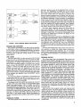
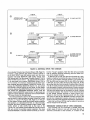
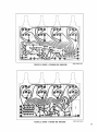
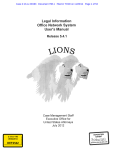
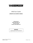
MONITOR MIXER SYSTEM
The rear-panel ACCESSORY OUTPUT/AUX LEVEL Connector (34) of the SR101 provides for interconnection to up
to eight Shure SR110 Professional Monitor Mixers. The output of each individual channel after the volume, equalization and attenuation channel controls appears on this
connector as do the LlNK INPUTIOUTPUT total mix signal
and the power supply connections. The SRI10 is a selfcontained, eight-channel, line level mixer designed for use
with the SRlOl Series 2 or similar equipment. The SR110
can provide a separate stage monitor "mix" that follows
the program "mix" levels coming from the eight channels
of the SR101. In addition, it may be used in making multitrack recordings: use two SRllOs for stereo and four for
quadriphonic.
The SR110 provides eight high-impedance, unbalanced,
line level inputs to its mixing circuitry, one high-impedance,
unbalanced, line level input to its Output Selector Switch
for monitoring the program mix, and one line level, 600ohm, balanced output. Individual channel and master volume controls are provided, as is a switch to choose between monitoring the channels in use (Mixed Inputs) and
the total program mix (Program Input). The Mixed Inputs
position takes the signal from each channel frequency
equalization circuit, and the Program lnput position obtains the mixed signal at the PRE LINK/POST LlNK Switch
(29).
The SR110 has parallel accessory inputloutput male and
female connectors. These connectors permit the connection of additional tandem or "stacked" SRllOs. A typical
application is shown in Figure 5, Page 9.
POWER
AMPLIFIER
PA
SPEAKERS
LEVEL
-
SRllO
MONITOR
MIXER
POWER
AMPLIFIER
STAGE
MONITOR
SPEAKER
I
SRllO
MONITOR
MIXER
STEREO
RECORDER
MONITOR
FIGURE 5. SR110 MONITOR MIXER APPLICATIONS
PROGRAM MIX AMPLIFIER
The program mix amplifier is an active mixing amplifier
in which gain remains constant independent of the number of individual channel PROGRAM Switches (13) that are
activated. The output of the program mix amplifier is connected through a 560-ohm mixing resistor to the LlNK
Jacks (28,31).
LlNK JACKS
The LlNK Jacks (28,31) on the rear panel of the Console
enable the user to interconnect more Consoles for additional inputs or add external equipment, such as equalizers,
compressors, or limiters. When connecting two or more
SR101 Audio Consoles together to provide many channel
inputs, connect the LlNK OUT Jacks (31) of all the units
together. It should be noted that the LlNK OUT Jack is
actually a two-way jack; the impedance at this point is
actually 600 ohms and any number of units may be tied
together at this point. The LlNK IN Jack (28) is an input-only
jack and has switching contacts that disconnect the output
of the program mix amplifier from the MASTER Volume
Control (20).
If an equalizer, limiter or compressor is connected to the
Console, the LlNK OUT Jack (31) is connected to the input
of the external unit and the output of the external unit is
connected to the LlNK IN Jack (28).
The signals at the LlNK JACKS are typically at a level 10
dB below line level. These jacks will accommodate signal
levels in the range between -30 to + I 0 dBm. The LlNK IN
input impedance is greater than 20 kilohms and may be
considered a bridging impedance. The output of the LlNK
Jacks feeds the MASTER Volume Control (20) which is a
two-section control similar to those used in the individual
channels. The POST LINK/PRE LlNK Switch (29) on the
rear panel, in the monitor circuit, allows the operator to
monitor the program before (PRE) or after (POST) the LlNK
Jacks.
FEEDBACK FILTERS
The output signal from the MASTER Volume Control (20)
attenuator section is sent to the feedback filter circuit at
this point. The FEEDBACK FILTERS (15) are four notch
filters whose center frequencies are 130 Hz, 800 Hz, 2 kHz,
and 5 kHz. T h e s e jil'lers a r e designed to minimize the
acoustic feedback (speaker howl or squeal) that may occur
through some combination of room acoustics, microphone
and speaker placement, volume increase, or equalization
control boost. Each filter modifies the frequency response
of the program output, with the lowest (130 Hz) filter affecting the lowest feedback pitch (howl) and the highest (5
kHz) filter affecting the highest feedback pitch (squeal).
The two center frequency filters affect feedback modes in
the middle ranges of the audio frequency spectrum.
The three upper frequency filters have little effect on
voice tonal qualities. The 130 Hz filter, generally used to
eliminate low-frequency room reverberations, causes some
decrease in bass tones. This may be compensated for by
increasing the FREQ EQ-LO Controls (5) slightly for the
individual channels in use.
If feedback is present, locate the one FEEDBACK FILTER
Switch (15) which eliminates it. Then increase the VOLUME
(1) or FREQ EQ Controls (5,7) as desired until another feedback pitch occurs. Then locate the filter to eliminate the
new feedback mode. IMPORTANT: Up to two FEEDBACK
FILTERS may be used at one time; more than two filters
will reduce overall gain and significantly affect system tonal
quality.
Note that the PHASE Switch (26), which allows the Console operator to change the output phase, functions to
reduce or eliminate acoustic feedback, too. It is normally
used to obtain maximum gain before feedback, or to obtain
the highest pitched feedback for elimination by the feedback filters.
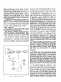
PROGRAM OUTPUT
The output signal from the feedback filters drives the
program output amplifier. The gain of this amplifier is controlled by one-half of the MASTER Volume Control (20) (the
other half is a preamplifier output attenuator). The output of
the program amplifier is sent to the PHASE Switch (26)
mounted on the rear panel of the Console. This switch
allows the user to change the phase of the program output,
which may be helpful in eliminating or reducing low-frequency acoustic feedback. Generally, this switch is adjusted to the position which either gives the most gain
before feedback or, if both positions give the same gain
before feedback, use the position that produces the highest
pitch feedback. The program signal, after leaving the
PHASE Switch, is routed to the output transformer which
provides both LlNE LEVEL and MIC LEVEL outputs. The
LlNE LEVEL output is connected to one professional threepin, male, audio output connector (27) and two three-circuit
phone jacks (25). The MIC LEVEL output is a low-impedance output, 50 dB below the LlNE LEVEL output, and is
connected to a professional three-pin male, audio output
connector (24).
Note that all of the program outputs are balanced with
respect to ground. If a phone plug is used to connect the
mixer line level output to an amplifier or tape recorder and
the phone plug is a two-circuit type, the line outputs will
automatically become unbalanced. If the 3-pin unbalanced
output is used and a phone jack output is also to be used,
obtain a stereo phone plug and connect the tip and ring of
the plug only. (The sleeve is a shield and would cause a
ground loop.)
If it becomes necessary to use the MIC LEVEL Output
Connector (24) to feed a high-impedance input, use a
matching transformer such as one of the Shure A95 Series
at the high-impedance input.
The output of the program output amplifier is also fed to
the VU Meter (17) circuit.
VU METER CIRCUIT
To allow a wide range of signals to be handled by the
VU Meter (17), a 22 dB VU Meter amplifier is provided. The
output of the program amplifier is fed to the METER SENSITIVITY Control (18) which in turn feeds the VU Meter amplifier and the Meter. The METER SENSITIVITY Control is
calibrated in its maximum counterclockwise position only.
The calibration of this position is internally adjusted at the
factory for +4 dBm at 0 VU across a 600-ohm load on the
program output. The VU Meter amplifier provides the
proper signal, impedance, and level for proper VU Meter
ballistics and calibration. This amplifier also isolates the
Meter from the program output and eliminates the distortion
normally caused by the nonlinearities of VU Meters.
TONE OSCILLATOR
The Console contains a built-in 1 kHz tone oscillator for
set-up and checkout purposes. The TONE OSC LEVEL Control a-nd ON-OFF Switch (16) injects the 1 kHz tone into the
program mix amplifier. The tone is processed through the
program channel in the same manner as microphone or
auxiliary input signals, except that the reverb system is
by passed.
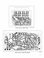
When using the tone oscillator, calibrate the Console VU
Meter (17) and proceed as follows: With the METER SENSITIVITY Control (18) set to CAL, increase the MASTER
Volume Control (20) and TONE OSC LEVEL Control (16)
until a 0 VU reading is obtained on the VU Meter. A tone
reference level has now been established. The Console
LlNE LEVEL Output (25,27) is now +4 dBm (1.23 volts) and
the MIC LEVEL Output (24) is approximately 4 millivolts.
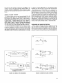
These reference signals may be used to set up power amplifiers, tape recorders, or other equipment connected to
these outputs (Figure 6A, Page 10). By adjusting the input
level (or volume) controls on the associated equipment, all
the meters in the audio system can be made to "track."
This allows the Console operator to observe the Console
VU Meter (17) to see if all the equipment is in its proper
operating range. This reference tone may also be used to
check out cables and equipment for proper operation.
To check a microphone cable, connect the cable between the Console MIC INPUT Jack (33) (any channel) and
the MIC LEVEL Output Jack (24) (refer to Figure 6B, Page
10). Connect headphones to the PHONES Jack (8). Release
the PROGRAM MONITOR Switch ( l l ) , and for the channel
being used, depress the MONITOR Switch (12), release the
PROGRAM Switch (13), and set the FREQ EQ Controls (5,7)
to 0, the channel Volume Control (1) to mid-range, and INPUT ATTEN Switch (14) to 0. An audible tone should be
heard through the headphones as the MONITOR Level
Control (10) is increased.
The same process may be used to check out a Console
channel. With a good microphone cable, make the connections described above. The tone should be heard clearly
through the headphones. If a channel is suspected of poor
quality, i t can be compared with another channel by connecting the microphone cable to the second channel with
all controls set in the same manner as the first. By care-
fully noting the level and quality of tone on each channel,
any significant differences can be established.
To check out an auxiliary channel, perform the process
described above, except connect a phone plug to phone
plug cable between the LlNE LEVEL Output Jack (25) and
the AUX. LEVEL Input Jack (32) for the channel (7 or 8)
being checked (Figure 6C, Page 10). Set the MIC/AUX
Switch (14) to AUX and INPUT ATTEN Switch to -30.
The tone oscillator may also be used to provide a check
of cables and equipment connected to the link output. With
the LINK OUT Jack (31) connected to the input of an external equipment, such as a Shure SE30 Gated Compressor1Mixer which in turn feeds a broadcast line, disconnect the program output, either at the back of the Console, power amplifier or speakers (Figure 6D, Page 10).
Turn the METER SENSITIVITY Control (18) to CAL, set the
MASTER Volume Control (20) to 7, and increase the TONE
OSC LEVEL Control (16) for a 0 VU Meter (17) reading.
Slide the MASTER Volume Control down to 0. Under this
set-up condition, the external equipment may now be calibrated or checked out without affecting the program output.
After calibrating the external equipment, turn off the tone
oscillator, and return the MASTER to 7. Reconnect the
power amplifier or speakers.
, ,, ,
MIC~
LINE^
ILINE,
SR I01
AUDIO CONSOLE
@
POWER
AMPLIFIER
)1
MIC L E V E L
INPUT JACK
TAPE
RECORDER
MIC LEVEL
OUTPUT JACK
SR l O l
AUDIO CONSOLE
0
INPUT
JACK
AUx.
LEVEL
n
LlNE L E V E L
OUTPUT JACK
SR 101
AUDIO CONSOLE
I
PHONES JACK
@
POWER A W L
AUX L E V E L
INPUT JACK
1
I
SR lOl
AUDIO CONSOLE
1
I
GATED
C0E;:SOR
MIXER
FIGURE 6. TON'E OSCILLATOR APPLICATIONS
1
1
BASIC OPERATING HINTS
Should any difficulty be encountered in Console operation, the problem may often be traced to some simple
source such as an error in interconnection. The following
is offered as a basic guide to problems of this sort.
Symptom: Console is "dead" (no output, VU Meter lamps
out)
Check:
1. Check that ac Dower source is "live" and
that Console is plugged in.
2. Check that POWER ON-OFF Switch (19) is
on.
3. Check to see that rear-panel 3AG-3116A
SLO-BLO Fuse (22) is good.
Symptom: Console is "dead" (no output, VU Meter lamps
lit)
Check:
1. Check that PROGRAM Switch or Switches
(13) are depressed.
2. Check that cable from PROGRAM OUTPUT/LINE LEVEL Connector (27) has not
accidentally been connected to PROGRAM
OUTPUT/MIC LEVEL Connector (24).
3. Check that PHASE Switch (26) is not between positions.
4. Check that external equipment is properly
connected to LINK Jacks (28,31).
Symptom:
One channel is "dead" (other channels operating properly)
Check:
1. Check for defective input cable or source.
2. Check that channel PROGRAM Switch (13)
is depressed.
3. Check that AUX-MIC Switch (14) (channels
7 and 8 only) is not between positions or in
the wrong position.
SR101 Series 2 Audio Console
SPECIAL OPERATING INSTRUCTIONS
The previous section described normal interconnection
and operation of the SR101 Audio Console; this section
provides information on special set-ups to more fully utilize
the capabilities of the Console.
HIGH-IMPEDANCE MICROPHONES
UP to two high-impedance dynamic, ribbon or condenser
microphones (crystal or ceramic microphones are not
recommended) can be used with the Console without the
need for line matching transformers simply by using the
AUX. INPUT Jacks (32) on channels 7 or 8 and moving the
corres~ondinclINPUT ATTEN Switch (14) to AUX. NOTE:
The very highoutput produced by s0m.e dondenser microphones may be compensated for by proper setting of the
INPUT ATTEN Control.
If a high-impedance microphone is to be used with one of
the low-impedance MIC LEVEL Input Jacks (33), a line
matching transformer (Shure A95 Series) must be used.
r
3.05 m (10') MAX.
The high-impedance cable should be limited to 6.lm
(20 ft.). If a long cable length is required, use up to 3.05m
(10 ft.) of high-impedance, single-conductor, shielded
cable (Belden #8401, #8410, or #8411) between the microphone and line matching transformer, and add as much
low-impedance, two-conductor, shielded cable (Belden
#8412,' or #8422) as necessary between the transformer
and Console input jack. These precautions will help avoid
high-frequency signal loss and reduce the possibility of
hum and noise.
INSTRUMENTS
Musical instruments, acoustical (non-electrified), acoustical-electrified, or electrified, may be amplified through the
Console. For acoustical instruments, place a microphone
close to the instrument strings, sounding board, or mouth.
Adjust equalization, reverb and volume controls as necessary.
-I
P
U
HIGH IMPEDANCE
AUX OR HEADPHONE
OUT
A95
LINE
MATCHING
TRANSFORMER
LOW IMPEDANCE
MIC LEVEL
INPUT
SR lOl
AUDIO CONSOLE
PREAMPLIFIER
-
1
P TO 3 0 5 m (1000')
r
LOW IMPEDANCE
MICROPHONE
CABLE
FIGURE 7. PREAMPLIFIER-CONSOLE CONNECTIONS
11
For acoustical-electrified instruments such as classic
or folk guitars with pickups and preamplifier outputs, or
pianos with pickups and preamplifier outputs, either place
the microphone as described above, or connect the pickup
to an AUX. LEVEL lnput Jack (32) on the Console. If the
cable from the instrument to the Console is greater than
6.lm (20 ft.), use a line matching transformer as described
under High-Impedance Microphones (Page 11). This transformer also allows the instrument to be connected to channels 1-6. Adjust the Console INPUT ATTEN Control (14) for
the channel in use to provide the desired sound level with
the channel Volume Control (1) set at about mid-scale.
To use a preamplifier auxiliary output with the Console
(instrument or tape recorder preamplifier, or hi-fi amplifier
tape monitor output jack, or headphone jack; never speaker
jacks), connect the preamplifier auxiliary output through
up to 3.05m (10 ft.) of cable to the high-impedance side of
a line matching transformer (Shure A95 Series) as shown
in Figure 7, Page 11. Connect the low-impedance side of the
transformer through a low-impedance microphone cable
[up to 305m (1000 ft.)] to a Console MICROPHONE LEVEL
lnput Jack (33). Adjust Console equalization controls for
optimum sound. Adjust the Console INPUT ATTEN Control
(14) for the channel in use to provide the desired sound
level with the channel Volume Control (1) set at about midscale.
Fully electrified instruments may also be amplified using
a microphone in front of the instrument speaker, or the instrument output (not the speaker jack) may be fed directly
to an input jack as described above. It is important to note
that the tonal quality of fully electrified instruments is primarily formed by the instrument amplifier and speaker; an
external microphone picking up the instrument speaker
output may very well provide a more desirable sound than
that obtained by direct connections.
The cable length restrictions applying to high-impedance
microphones also apply to most musical instruments (see
High-Impedance Microphones, Page 11).
TAPE RECORDING
The Console output may be recorded on a tape recorder
from either the LlNE LEVEL Output (25,27), MIC LEVEL
Output (24) or LlNK OUT (31) Jacks. The Console Program
Outputs are after the FEEDBACK FILTERS (15) and MASTER Volume Control (20); the LlNK OUT Jack is before
these circuits. In considering a tape recorder connection,
the operator should consider whether he wants the tape
level to follow the MASTER Control.
To use a LlNE LEVEL Output Jack feeding a high-impedance auxiliary tape recorder input, connect a cable from
one LlNE LEVEL Jack to the tape recorder input (see Figure 8, Page 12). If the LINE LEVEL Output is being used and
a two-circuit phone jack is used to connect the Console to
the tape recorder, this will unbalance the LlNE LEVEL Output (refer to Program Output, Page 9).
If the MIC LEVEL Output Jack (24) is to be used, connect
a cable from i t to the tape recorder low-impedance microphone input. If the microphone input on the tape recorder
is designed to be used with high-impedance microphones
(greater than 1000 ohms), insert a line matching transformer (Shure A95 Series with proper connectors) between
the MIC LEVEL Output Jack and the tape recorder input
(refer to Program Output, Page 9).
To use the LlNK OUT Jack (31), use a two-circuit phone
plug on the cable to the tape recorder auxiliary or line input.
The input impedance of the tape recorder should be 600
ohms minimum.
The low output impedance of the Console provides for
unlimited cable length between the Console output and
tape recorder input. Low-capacitance, single-conductor,
shielded cable (Belden #8401, #8410, or #8411) is recommended to reduce the possibility of hum and noise pickup.
For operation with a stereo tape recorder, refer to Stereo
Operation, Page 16.
LOW IMPEDANCE
BALANCED L l N E
SHIELD
MIC L E V E L OUTPUT
\
\
\
\
\
TRANSFORMER
SRlOl
AUDIO CONSOLE
RECORDER
FIGURE 8. TAPE RECORDING
RECORD PLAYBACK
To play records through the Console using a turntable
or record changer with a stereo magnetic cartridge and no
preamplifier, the most expedient method is to join the left
and right channel leads from the turntable in a "Y" adapter
and connect the joined output to a channel 7 (or 8) AUX.
LEVEL lnput Connector (32) on the Console (see Figure 9A,
Page 13). Note that the total lead length between turntable
and Console should not exceed five feet. To approximate
the RlAA equalization curve, set the Console FREQ EQ-LO
Control (5) to +4, the FREQ EQ-HI Control (7) to -6, and
the INPUT ATTEN Control (14) to 0 for the channel (7 or 8)
being used. Adjust the channel Volume Control (1) as
necessary.
A better method of performing this interconnection involves the use of a phono preamplifier such as the Shure
M64 Stereo Preamplifier (see Figure 96, Page 13). In this
set-up, RlAA equalization will be achieved at the preamplifier, before the signal enters the Console. In this manner,
the Console equalization controls may be used to optimize
the room sound, rather than compensating for the input
signal. The joined turntable leads enter the channel 1 input
of the preamplifier, and the output is taken from the channel
1 low level output and fed to the channel 7 (or 8) AUX.
LEVEL lnput Jack (32) of the Console. Set the Console
INPUT ATTEN Control (14) to 0 with this set-up.
Note also that this set-up removes the cable restriction
between turntable and Console described above: although
a maximum of 1.5m (5 ft.) between turntable and preamplifier is mandatory, the cable length between the preamplifier and Console is virtually unlimited.
TAPE PLAYBACK
To play tape-recorded material through the Console,
connect a cable from the tape recorder auxiliary or line
level output to the channel 7 or 8 AUX. LEVEL lnput Jack
(32). Turn the front-panel AUX-MIC Switch (14) on Channel
7 or 8 (whichever is being used) to AUX. Set the INPUT
ATTEN Switch (14) to -20 to start, and adjust it and the
channel Volume Control (1) as required.
@
,
l
T
l
.
5
~
~
~
m
~
,
y
CHANNEL 7 OR 8
AUX LEVEL INPUT
SR lOl
AUDIO CONSOLE
TURNTABLE
1.5 m
@
(5') MAX.
P
3
CHAN. I
I
INPUT
FREQ. EQ-LO: + 4
( FREQ. EQ-HI:
*
M 6 4 STEREO
PREAMPLIFIER
U
P
-6
TO 305 m
)
(1000')
CHAN. I
LOW LEVEL
OUTPUT
AUX LEVEL INPUT
SR lOl
AUDIO CONSOLE
TURNTABLE
?# ONLY ONE CHANNEL IS USED FOR THIS APPLICATION.
FIGURE 9. RECORD PLAYBACK
TALKBACK CIRCUIT
It is often necessary to provide a "talkback" circuit (or
"intercom," or "com line") to enable the Console operator
to instruct or cue performers, lighting control, announcers,
etc. It also enables the operator to avoid hand or light signals which may not be visible during a performance. The
talkback circuit requires the use of one input channel, removing that channel from use by performers. Note too that
the monitor circuit is being used, preventing its use for
other purposes.
To use low-impedance (not carbon) microphones, connect the microphone of a single headset-microphone to a
Console MIC LEVEL lnput Jack (33) (see Figure 10, Page
13). Connect the headset to the front-panel PHONES Jacks
(8). For high-impedance headphones, connect to the rearpanel MONITOR LlNE LEVEL Jack (30). Additional headsets may be connected through "Y" adapters to the
PHONES or MONITOR LlNE LEVEL Jack. If additional
microphones are to be connected, "Y" adapters (Switchcraft 391Q13,391Q53 or equivalent) should be used to connect these to the MIC LEVEL lnput Jack. Depress the
MONITOR Switch (12) for the talkback channel and adjust
the MONITOR Level Control (10) as desired. Do not depress
the PROGRAM Switch (13).
If this set-up does not work, and the microphone type
being used is unknown, i t is possible that it is a carbon
microphone. To use carbon microphones such as found in
Western Electric-type operator's headsets, a battery power
supply is required to power the microphone (see Figure 11,
Page 13). A common battery may be used for powering a
number of carbon microphones, though each microphone
requires its own 100-ohm resistor and Shure A95 Series
line matching transformer.
Should a large number of headphones be required, a
power amplifier or headphone distribution amplifier should
be inserted in the headphone circuit between the MONITOR LlNE LEVEL Output (30) and the distribution amplifier
input.
LOW
IMPEDANCE
100 OHMS
1/2 W
3-6V
LANTERN
BATTERY
NEDA
915
MIC
LEVEL
IN
L
+
,
-
,
SR lOl
AUDIO CONSOLE
I PHONES
FIGURE 10. TALKBACK CIRCUIT
,908
D
CARBON
MICROPHONE
-
FIGURE 11. CARBON MICROPHONE POWER SUPPLY
ADDITIONAL MIXER INPUTS
Additional microphone or other source inputs may be
obtained using a high gain, low noise, microphone mixer
such as the Shure M68FC. When connected to a MIC
LEVEL lnput Jack (33), the M68FC and SR101 Audio Console will provide a total of 11 inputs (see Figure 12A, Page
14). (Note that adding a mixer at an lnput Jack converts
that channel to a submaster control; the total number of
inputs will thus be the mixer total plus the Console total 8 - minus 1 for the submaster.)
A common practice when adding a mixer in this manner
is to connect similar-use microphones (for instance, all
drum, string or horn microphones) to a single mixer which
is fed into the Console. The Console individual channel
Volume Control (1) then controls an entire section, facilitating adjustment of that section during a performance.
With this set-up, set the channel INPUT ATTEN (14) to 0 and
adjust the mixer volume controls in the mid-to-high range;
adjust the mixer master volume control as required to keep
the Console volume control in the desirable middle range.
The M68FC mixer has a switch-selectable low- or highimpedance microphone output. When using an M68FC-type
mixer into a Console MIC LEVEL lnput Jack (33), set the
mixer MIC OUT switch to low impedance, and make necessary adjustments as described above. It is sometimes desirable to use the auxiliary output from the mixer into the
Console channel 7 (or 8) AUX. INPUT Jacks (32) if the mixer
output is derived from a source which is not required constantly (such as an orchestra); the same channel 7 (or 8)
MIC LEVEL lnput Jack can be used as a regular microphone
input, with the front-panel AUX-MIC Switch (14) selecting
one or the other for the program. (Refer to lnput Channels,
Page 5, for a description of the AUX-MIC Switch function.)
To use this set-up with an M68FC mixer, connect a cable
between the mixer auxiliary output (phono pin jack) and the
Console AUX. INPUT Jack (32) on channel 7 (or 8) (phone
jack) (Figure 128, Page 14). Set the Console INPUT ATTEN
Control (14) to -20. To use this set-up with other mixers,
LOW IMPEDANCE
MIC L E V E L
MIC L E V E L
AUX L E V E L
AUX L E V E L
MlXER
LINE OUT OR
PHONES OUT
0
AUX L E V E L
MIXER
PHONES
SRlOl
MIXER
I
6 0 0 n
L I N E OUT
MIXER
;IP;
SRlOl
AUDIO CONSOLE
,
TOTAL: I 2 CHANNELS
I N 0 EQUALIZATION OR
REVERB ON ~ 6 INPUTS)
7
FIGURE 12. ADDITIONAL MIXER INPUTS
essenfially the same procedure is followed. The Shure M67
mixer, for instance, may be connected to the Console AUX:
INPUT Jack through the mixer line out connector (binding
posts) or headphone output (phone jack) (Figure 12C, Page
14). Because of the difference in outputs between 'the
M68FC and M67, the Console INPUT ATTEN Control, when
used with the M67, should be set at -30. Note that the
M67 microphone output should not be used into the Console AUX. INPUT without a line matching transformer.
If a mixer is to be used with the Console but it is desirable
to maintain as many Console channels as possible, the
mixer can be connected to the Console LlNK OUT Jack (31)
(Figure 12D, Page 14). However, this requires sacrificing
the channel reverb, equalization and monitor functions for
the sources entering through the mixer (monitoring of the
total program can still be accomplished with the POST
LINKIPRE LlNK Switch (29) set to POST LINK). The only
Console control functions operating on the mixer sources
in this set-up are the MASTER Volume Control (20), FEEDBACK FILTERS Switches (15), and rear-panel PHASE
Switch (26). In addition, any mixer used in this set-up requires a 2.2-kilohm resistor in series with the mixer output
to provide an attenuator bridging connection; the resulting
signal level will be down -10 dB (see Figure 12D, Page
14). The M67 Mixer headphone jack has suitable built-in
resistors and may be connected directly to the Console
LlNK OUT Jack. Only mixers with 600-ohm line outputs may
be used in this configuration. Note that the Shure M68FC
mixer cannot be used this way.
The mixer-to-link jack connection can also be used with
several mixers. Each mixer output must contain its own
2.2-kilohm resistor prior to being joined in a "Y" adapter.
Any number of M67 mixers may be interconnected by
connecting their headphone jacks in parallel. The paralleled headphone output is then connected to a Console
AUX. LEVEL lnput Connector (32). The INPUT ATTEN
Control (14) should be set at -20 as an initial position and
adjusted in balance with the M67 meter reading and the
channel 7 (or 8) Console Volume Control setting (1). In this
set-up the M67 VU meter switch should be set at +4, the
master volume to 3, and the individual volume controls to
7 or 8.
ADDITIONAL CONSOLE INPUTS (TWO CONSOLES)
A total of 16 microphone inputs can be obtained using
two Consoles in a common mix mode. Connect a cable to
the "slave" Console LlNK OUT Jack (31) and to the "master" Console LlNK OUT Jack (Figure 13A, Page 15). Note
that the LlNK OUT Jack is both an input and output jack.
This interconnection provides a two-way path between the
two Consoles. When operating the two Consoles side by
side, the slave input can be monitored on the master Console as part of the total program output with the POST
LINK/PRE LlNK Switch (29) set to POST LlNK and the
PROGRAM MONITOR Switch (11) depressed. With the
POST LINKIPRE LlNK Switch in the PRE LlNK position the
Program Monitor only monitors the eight inputs on that
Console. The monitor point is switched ahead (PRE) of the
LlNK Jacks. In this set-up both Consoles contain the total
program mix. Each Console MASTER Volume Control (20)
is independent, and may be used to control two separate
program outputs.
An expansion of this method of interconnecting two Consoles which will enable full monitoring involves the sacrifice
@
OPTIONAL SLAVE
8 INPUTS
8 INPUTS
A
A
1111111
OUT
LINK
"SLAVE"
SRlOl
AUDIO CONSOLE
@
8 INPUTS
OUT
LINK
111111I
TO POWER AMPLIFIER
LINE
OUT
"MASTER"
SRlOl
AUDIO CONSOLE
7 INPUTS
TO POWER AMPLIFIER
AUDIO CONSOLE
AUDIO CONSOLE
0
TO POWER AMPLIFIER,
BROADCAST LINE. OR
TAPE RECORDEE
TO HOUSE PA
FIGURE 13. ADDITIONAL INPUTS: TWO CONSOLES
of one master Console input channel (Figure 13B, Page 15).
Connect a cable between the master Console channel 7
(or 8) AUX. INPUT Jack (32) (phone jack) and the slave
Console rear-panel MONITOR LlNE LEVEL Output Jack
(30) (phone jack). Set the master Console channel 7 (or 8)
INPUT ATTEN Control (14) to -30, channel Volume Control
(1) to mid-range, and channel PROGRAM Switch (13) to
off. To monitor, for instance, channel 2 on the slave Console, depress the slave channel 2 MONITOR Switch (12),
release the PROGRAM MONITOR Switch ( l l ) , and preset
the channel 2 Volume Control to mid-range. On the master
Console, depress the MONITOR Switch for channel 7 (or 8),
and release the PROGRAM MONITOR Switch. With the
master Console MONITOR Level Control (1) previously adjusted for normal listening, adjust the slave Console MONITOR Level Control for the same level.
The interconnections used in the above paragraph may
also be used in a set-up where the slave Console is to feed
a built-in, or "house" PA (Figure 138, Page 15). In this setup, the master Console feeds the portable power amplifier
and speakers, or a broadcast line feed, or a tape recorder.
Connect the slave Console program output, either LlNE
LEVEL (25,27) or MIC LEVEL (24) to the input of the
"house" PA. The master Console MASTER Volume Control
(20) will control the portable system speakers; the slave
Console MASTER or channel Volume Controls (1) will con-
trol the "house" speakers. Note that this set-up provides
total or selective channel monitoring from the slave Console at the master Console.
A different set-up that uses the slave Console as a submaster is made by connecting the slave Console LlNK OUT
Jack (31) to the master Console channel 7 (or 8) AUX. INPUT Jack (32) and the slave LlNK IN Jack (28) to the master
LlNK OUT Jack (31) (refer to Figure 13C, Page 15). In this
set-up the total mix from the slave Console enters channel
7 (or 8) on master Console channels and may be monitored
from the master Console; individual slave Console channels
must be monitored from the slave Console monitor system.
This set-up is helpful.when an orchestra (or band) is mixed
on the slave Console. The channel 7 (or 8) Volume Control
on the master Console provides a single control (submaster) to mix the total orchestra sound with the vocals.
The result is that the two MASTER Volume Controls (20)
provide two independent outputs, each with the total program mix and each with separate equalization adjustments.
Note that two Shure SRllOs may be added to provide a
monitor output for the 16 inputs.
REDUNDANT CONSOLE SET-UP (TWO CONSOLES)
Two Consoles can be connected in parallel such that
certain types of failure in one will not cause the loss of
channels connected to that Console; in a failure in the
output of one Console, the channel inputs of both units
will be routed through the operative Console. This type of
system is termed "redundant," that is, the reliability of the
system is enhanced through parallel functioning devices.
Connect a cable between the LlNK OUT Jacks (31) of
each Console. Construct a resistor network as shown in
Figure 14, Page 16, and insert it between the LlNE LEVEL
Output Jacks (27) on both Consoles and the balanced
bridging input of the power amplifier. The resistor network
matches the output of the two Consoles to the balanced line
to the power amplifier.
A method of total redundancy using two Consoles is to
parallel-connect ("Y") all inputs using Switchcraft 391Q13,
391Q53 or equivalent adapters. The second (redundant)
Console may be kept on with all Volume Controls (1,20)
down, and the required controls brought up to the desired
level only upon. failure of one channel. The same output
attenuator network as described above is required.
STEREO OPERATION
Stereo operation, for PA or tape recording purposes,
may be accomplished in several ways. The most common
are described in the following paragraphs.
Stereo operation is most easily achieved using the setup previously described in Monitor Mixer System, Page 8.
The use of Shure SRllOs as shown in Figure 5, Page 9,
provides for a stereo tape recorder mix which is separate
from the PA and stage monitor mixes.
Stereo operation may obviously be obtained by using
two Consoles in separate PA systems without any system
interconnections. If i t is desired to have one microphone
connected to both systems, use a. "Y" adapter (Switchcraft 391Q13, 391(2.53 or equivalent) on the microphone
and feed its output to a MIC LEVEL lnput Jack (33) on
r
LlNK
OUT
SR lOl
AUDIO CONSOLE
LINE
LEVEL
RESISTIVE
NETWORK
POWER
AMPLIFIER
I
J
I
I
I
I
LINK
OUT
I
I
SRlOl
AUDIO CONSOLE
LlNE
LEVEL
LINE LEVEL
I
I
I
I
I
I
POWER
AMPL
BALANCED
BRIDGING
INPUT
RESISTORS ARE CARBON COMP.. 112 W,5%
I
FIGURE 14. REDUNDANT CONSOLES
16
each Console. To record stereo tapes with this set-up,
connect the LlNE LEVEL Output Jack (25) on one Console to the left input channel of a stereo tape recorder and
the LlNE LEVEL Output Jack on the other Console to the
right input channel.
An alternate method of stereo operation using only a
single Console involves the use of the program output system as one stereo channel (right) and the monitor output
system as the other channel (left). With microphones placed
for stereo effect, connect a PROGRAM LlNE LEVEL Output Jack (25) to the right power amplifier and speaker set
(or the right channel input of a stereo tape recorder), and
the MONITOR LlNE LEVEL Output Jack (30) to the left
power amplifier and speaker set (or the left channel input
of the stereo tape recorder). Depress the channel PROGRAM Switches (13) for the microphones assigned to the
right, and depress the MONITOR Switches (12) for microphones assigned to the left. Release the PROGRAM MONITOR Switch (11). Center microphones may be assigned
to both left and right channels by depressing both PROGRAM and MONITOR Switches for those inputs. Note that
the channel MONITOR Switches should be preset and not
changed during a performance because the total MONITOR
level changes as a function of the number of inputs assigned to the MONITOR system. Also note that reverb is
obtainable only on those inputs whose PROGRAM Switches
are depressed. This set-up works well for stage plays
where the left and right speakers are closely spaced,
such as to the sides of a narrow stage, and are projecting
into a deep room. Shure speaker columns are an ideal
speaker choice because of their wide horizontal coverage
pattern.
A convenient method of stereo recording is to record
the vocals on one tape channel and the instruments on
the other. For this set-up, connect either the Console MIC
LEVEL (24) or LlNE LEVEL (25) Output Jack to one channel input of a stereo tape recorder (refer to Tape Recording, Page 12). Connect a microphone to the remaining
tape channel input; an omnidirectional unit suspended
from the ceiling will pick up the full acoustic output of the
instruments.
An expansion of the stereo recording set-up described
above-separate vocal and instrument channels-depends
on whether the stereo tape recorder to be used has a
single set of inputs (MIC) or whether i t also has auxiliary
(AUX) inputs with separate volume controls. With microphone and auxiliary inputs, connect the system as shown
in Figure 15A, Page 17. Place the vocal microphones as
required and connect them to the MIC LEVEL lnput Jacks
(33) of the Console. Connect the LlNE LEVEL Output Jack
(25) through a "Y" adapter to the auxiliary inputs of the
tape recorder. Place the instrumental microphones as required and connect them to the microphone inputs of the
tape recorder.
If the stereo tape recorder has a single set of inputs,
that is, when the auxiliary inputs are connected, the microphone inputs are disconnected, or if separate volume control of the microphone and auxiliary inputs cannot be main.tained, then a stereo mixer such as the Shure M688 may
be used to combine the Console output prior to entering
the recorder (refer to Figure 15B, Page 17). Place the vocal
microphones and connect them to the Console MIC LEVEL
lnput Jacks (33). Connect the Console MIC LEVEL Output
Jack (25) to the MIC 4 input of the M688. Place the instrumental microphones as desired and connect them to the
MIC 1 (left) and MIC 2 (right) inputs of the M688. Connect
the left and right auxiliary outputs of the M688 to the
auxiliary inputs of the tape recorder. Before making recordings, adjust the M688 MIC 4 slide control to a midposition for the most desirable balance of vocal microphone
levels.
REMOTE VOLUME CONTROL
A remote volume control may be constructed for' adjusting the output level at a considerable distance from
the Console. For remote control up to 50 feet, obtain a
linear-taper potentiometer with knob (any value from 1000
to 2500 ohms), a standard phone plug, and a length of
single-conductor, shielded microphone cable (such as
Belden #8401, #8410, or #8411). Connect the potentiometer and plug as shown in Figure 16A, Page 17, and connect the phone plug to the Console LlNK OUT Jack (31).
If hum or noise is encountered with the above set-up,
it may be necessary to provide a two-wire control. Using
the same potentiometer, obtain two standard phone plugs
and twice the desired length of single-conductor, shielded
microphone cable. Connect the potentiometer and plugs
as shown in Figure 16B, Page 17, and plug the control
assembly into the LlNK OUT (31) and LlNK IN (28) Jacks.
For distances over 15.2m (50 ft.) or for permanent installations where hum or noise may be encountered, use
low-capacitance, two-conductor, shielded cable (Belden
#8412 or #8422). Connect as shown in Figure 16C, Page
17, and use a metal box to contain the potentiometer. The
cable shield must be connected to the metal box containing the potentbmeter, to the common conductor (black),
and not to the sleeve connections of the phone plugs.
IMPORTANT: To avoid hum caused by a ground loop, do
not ground the metal box to any metal such as electrical
conduit, water pipes, heating ducts, or structural steel.
TELEPHONE LlNE SURGE PROTECTION
When using the Console to feed a telephone line that
may be subject to lightning-induced voltage surges, the
following part should be installed across the telephone
line to provide additional protection for output circuit components: Thyrector, General Electric Part No. 6RS20SPlBl.
--
LlNK
SR 101
AUDIO CONSOLE
-j
OUT
I
1 +a
-
-
STEREO
-
SR 101
AUDIO CONSOLE
0
RECORDER
(INSTRI
SRlOl
AUDIO CONSOLE
( "OCAL'
@
MIC IN
--
h ::
D
(INSTRI
D
L
M688
STEREO
MIXER
rT
R
*NOTE,
THIS TYPE OF RECORDER DOES
HAVE SEPARATE
MIC AND AUX CONTROLS,AND PLUGGING IN THE
AUX I N N 1 JACK USUALLY DISCONNECTS
THE MIC INPUT.
FIGURE 15. STEREO TAPE RECORDING
STEREO
TAPE
RECORDER
SRlOl
AUDIO CONSOLE
LINK
)N
1
1
I
L- - - - - - - - - J
FIGURE 16. REMOTE VOLUME CONTROL
SR101 Series 2 Audio Console
SERVICE INSTRUCTIONS
CONSOLE SERVICE (SEE GUARANTEE, Page 22.)
The SR101 Audio Console uses components of the highest quality, operating well within their respective ratings
to assure long life.
WARNING
Voltages in this equipment are hazardous to life. Make
all input and output connections with ac power disconnected. Refer servicing to qualified service personnel.
REPLACEMENT PARTS
Parts that are readily available through local electronic
parts distributors are not shown on the accompanying
Parts List. Their values are shown on the Circuit Diagram
(Figure 31, Pages 44-45). Commercial parts not readily
available and unique parts are shown on the Parts List
and may be ordered directly from the factory.
The commercial alternates shown on the Parts List are
not necessarily equivalents, but may be used in the event
that direct factory replacements are not immediately available. To maintain the highest possible performance and
reliability Shure factory replacement parts should be used.
When ordering replacement parts, specify the Shure Replacement Kit Number (RKC), description, product model
number, and serial number.
FUSE REPLACEMENT
To replace line fuse F1 (with no apparent problems in
the Console), disconnect the line cord from the ac source
and remove the rear-panel fuseholder cap. Replace the
defective fuse only with a 3AG-3/16A Slo-Blo fuse (SRI01
only; SR101-2E contains a 0.1A Slo-Blo fuse for 180- to
250-volt operation, or a 0.2A Slo-Blo fuse for 90- to 132volt operation).
CAUTION
If trouble symptoms-overheating, erratic operation,
etc.-were apparent before the fuse blew, or if the replacement fuse blows, a qualified serviceman should
troubleshoot the Console carefully to find the source
of the trouble. Do not continue to replace fuses
until the trouble has been corrected.
The Console also contains two wired-in fuses, one in
series with rear-panel line fuse F1 (F2, 3/10A, Slo-Blo) and
one in the meter and accessory lamp circuit (F3, I A , SloBlo). If replacement becomes necessary, replace only
with identical fuses.
KNOB REPLACEMENT
All front-panel control knobs are pull-off types and are
interchangeable with others of the same function. The
only exceptions are the channel 7 and 8 INPUT ATTEN
Switches (S7,S8) which contain separate AUX-MIC knobs.
When ordering replacement knobs, be sure to order the
proper color-coded type for the desired control.
SERVICE ACCESS
To open the Console for servicing, carefully place the
Console front-panel downward on a firm, flat, padded surface. A rubber, plastic, corrugated cardboard, or cloth pad
should be placed between the work surface and the Console controls. Remove the three Phillips head screws securing the upper and lower rear panels to each other, the
four Phillips head screws securing the lower rear panel to
the Console sides, and the two Phillips head screws securing the upper rear panel to the Console sides. Open the
two halves to the limit of their hinges (lower half first) to
obtain access to the printed circuit boards (NOTE: Although not normally required for servicing, the lower
panel may be completely removed from thi Console by
removing two hex-head screws, one at either side of the
consolecase, and disconnecting the black ground lead.)
LAMP REPLACEMENT
To replace either of the two #47 lamps (PLI,PL2) illuminating the VU Meter (MI), carefully raise the metal clip
assembly holding the lamp to be replaced upward and
off the Power Supply printed circuit board bracket. Lift
the lamp socket upward, taking care not to crimp or
break any associated wiring. Replace the defective lamp
and carefully return the lamp assembly to its original
position.
REVERBERATION ASSEMBLY
To remove the Reverberation Assembly (AlO), first disconnect the input, output and ground leads. Remove the
four Phillips head screws securing the assembly to the
lower rear panel and remove the assembly. If the Console
is to b e operated with the Reverb Assembly removed, make
sure the associated wires are not left free to short out any
other wiring. Remove the input and output wires from the
Reverb Spring Amplifier circuit board, and remove the
ground wire from its lug.
BOARD REMOVAL
The various printed circuit boards are mounted in different manners. The following paragraphs describe the
best method of removing these boards after wires and
cable assemblies have been removed. IMPORTANT: When
disconnecting push-on terminals or soldered board connections, make sure each wire is identified for proper reconnection. This may be done by affixing a piece of masking tape marked with the connection or terminal letter or
color to each wire.
CAUTION
Push-on terminals must be removed by pulling terminals straight up from printed circuit board surface.
Do not apply side force when removing or reconnecting terminals, or damage may result.
Refer to Figure 17, Page 19, for location of each board.
AIO
MP12
AI-A9
1 ""
"i16
J'"
TI-TB
R27
RIB - R E 0
J"'/
J12
RIA-R8A
BD.5
R168
~"3""
1' I"\ " \"" \
s"
J17
J21
JII
J14
J15
FIGURE 17. PRINTED CIRCUIT BOARD AND PARTS LOCATION
J13
The function of each board assembly is defined in the
table below.
Component
Board No.
Function
1
2A
28
3
4
5
6
7
8
9
0
Preamplifier Board
~ ~ u a l i z Boards
er
(8)
Reverb Equalizer Board
Program Mix Amplifier Board
Reverb Mix Amplifier Board
Program Output Board
Feedback Filters Board
Reverb Spring Amplifier Board
Monitor Board
Power Supply Board
Program Mute Board
A magnetic screwdriver is recommended for board fastener
removal. When removing front-panel control or switch
retaining nuts with a M " nutdriver or wrench, be careful
not to damage the black plastic surface.
Preamplifier Board (1): Remove the seven screws securing the board to the upper rear panel, disconnect the eight
color-coded channel output leads, and lift the board up
and over for service access. When re-fastening the board,
be careful not to crimp wires or wiring assemblies beneath
the board.
Channel and Reverb Equalizer (Board 2): Each of these
nine boards may be removed by removing the two frontpanel equalizer control knobs and retaining nuts associated with that channel. The eight Channel Equalizer
boards (not the Reverb Equalizer board) are identical and
may be interchanged without modification.
Program Mix Amplifier (Board 3): Remove the four
front-panel REVERB INTENSITY Control knobs and retaining nuts for channels 5 through 8, and lift the board
straight up.
Reverb Mix Amplifier (Board 4): Remove the four frontpanel REVERB INTENSITY Control knobs and retaining
nuts for channels 1 through 4, and lift the board straight up.
Program Output (Board 5): Remove the three screws
securing the board to the front panel and lift straight up.
(NOTE: The VU Meter Calibration resistor (R529) is accessible without removing the board.)
Feedback Filters (Board 6): Remove the two screws securing the filter switch frame to the front panel and lift
straight up. Be careful not to damage the electrostatic
foil shield when removing or inserting board.
Reverb Spring Amplifier (Board 7): Remove the four
screws securing the board to the front panel and lift straight
UP.
Monitor (Board 8): Remove the two side-panel screws
securing the bracket above the Monitor board. Remove the
two screws securing the board and lift the board straight
UP.
Power Supply (Board 9): Remove the four screws securing the board and lift straight up.
Program Mute (Board 0): Remove the two screws securing the bracket on which transformer T9 and the Program
Mute board are mounted. Turn the bracket so that the
four screws securing the Program Mute board can be
removed. When replacing the board, be sure to pass the
same wires between the board and bracket as were removed.
VU METER REMOVAL
If the VU Meter ( M I ) requires replacement, remove it
as follows. Disconnect all push-on terminals on the Power
Supply board (Figure 17, Page 19). Remove the t&o screws
securing the Power Supply bracket to the side panel. Swing
the Power Supply bracket to one side, exposing the VU
Meter. Remove the two wires connected to the VU Meter.
Remove the two screws in recessed slots near the meter
electrical contacts; this will free the meter retaining brackets, bracket screws, and rubber feet. Carefully pass the
meter assembly out through the front panel. To reassemble
the meter, reverse the above steps, taking care to insert
the bracket screws in the closed-end eyelets in the rubber
feet and tighten them as necessary to retain the meter
against the front panel.
CAUTION
Do not overtighten screws so as to deform meter
retaining brackets.
Make sure the red and green leads from transformer T I 1
are positioned behind the electrostatic foil shield flap attached to the Feedback Filters board.
VU METER CALIBRATION
With the Console turned off, the front-panel VU Meter
( M I ) should read 0 on the lower of the two meter scales.
If it does not, adjust the screw below the meter face to
obtain the correct reading.
To calibrate the meter, connect an ac voltmeter across
the PROGRAM LINE LEVEL OUTPUT (J14-J16). Turn on
the Console and adjust the TONE OSC LEVEL Control (R9)
and the MASTER Volume Control (A9) until a reading of
+4 dBm (1.228V across 600 ohms) is obtained on the voltmeter. Turn the front-panel METER SENSITIVITY Control
(R17) to the CALIBRATE position. Adjust potentiometer
R529 (VU Calibrate) on the Program Output board until the
VU Meter reads 0 on the upper of the two scales.
Note that the VU Calibrate potentiometer range allows
the VU Meter to be adjusted to 0 for any output between
0 dBm and +8 dBm.
VOLUME CONTROL ASSEMBLY
To replace a channel or MASTER Volume Control assembly (Al-A9), proceed as follows. Pull off the front-panel
slider knob for the assembly to be replaced. Unsolder the
leads connected to each potentiometer in the assembly,
noting each lead connection. (Note that the lower potentiometer-"B" section-utilizes only two of the three leads.)
Remove the two screws and lockwashers securing the
assembly to the front panel. Carefully lift the Volume Control assembly up and out of the unit. Replace the new
assembly by reversing the above steps.
To replace the black plastic dust cover (MP12) surrounding the Volume Control assembly (see Figure 18, Page 21),
remove the assembly as described in the paragraph above.
Remove the original dust cover by lifting both ends
off the slide actuator and sliding the dust cover out from
beneath the guide attached to the side of the mounting
bracket opposite the actuator. Attach one end of the new
dust cover to the slide actuator and pass the other end
over the lower black plastic bearing assembly. Insert the
loose end between the metal guide and synchronizing
POTENTIOMETERS
RIA-RBA, R16A
\
SYNCHRONIZING
POTENTIOMETERS
RIB-R88, R16B
SLIDE ACTUATOR
/
APPROXIMATELY
1/16 IN. PLAY
LOWER
BEARING
ASSEMBLY
'-SETSCREW
\LOWER
PULLEY
FIGURE 18. VOLUME CONTROL ASSEMBLY
belt, pass it over the upper black plastic bearing assembly,
and attach it to the slide actuator. Reassemble the Volume
Control assembly as described above.
To replace one of the linear volume potentiometers
(Rl-R8: individual channels; R16: MASTER), remove the
assembly and dust cover as described above. Using an
0.050" Allen wrench, loosen and remove the pulley attached to the potentiometer to be replaced and the synchronizing belt. (NOTE: The upper potentiometer is the
"A" section and the lower is the "B" section for each
Volume Control assembly.) Use a 3/8" wrench to remove
the old potentiometer. Position the new potentiometer in
the mounting bracket, leads extending away from the
actuator side of the assembly, and finger-tighten the 3/e"
mounting nut. From the potentiometer shaft side of the
assembly and with the actuator upward, rotate both potentiometer shafts clockwise (from shaft side) to their
stop positions. Note the setscrew position on the remaining pulley. Carefully insert the removed pulley, washer
side toward mounting bracket, with the setscrew facing in
the same direction as the setscrew on the other pulley.
Slip on the synchronizing belt over the two pulleys.
Before tightening the %I' nut on the replaced potentiometer, position the upper potentiometer to provide
about %,'I (1.6 mm) play in the belt. The upper potentiometer is adjustable to set synchronizing belt tension:
if the lower potentiometer has been replaced, tighten the
lower potentiometer and loosen, adjust and tighten the
upper potentiometer. If the upper potentiometer has been
replaced, adjust i t for proper belt tension, and tighten.
(NOTE: The simplest method providing proper belt play
is to hold the assembly by the mounting frame vertically
with the actuator resting on the platform of a small postal
scale or attached to a small spring scale, and move the
assembly downward. A 1 pound maximum-approximately
454 grams-force should be required to move the actuator.)
When the potentiometer is properly positioned, tighten
the 3/s" mounting nut. Make sure the replaced pulley
is aligned with the center of the nearest black plastic
bearing assembly and tighten the pulley setscrews. Move
the actuator along the length of its travel. The actuator
should move smoothly from one end to the other. If it
stops before reaching the end of its normal movement,
gently but firmly force the actuator to "jump" as many teeth
as necessary to reach the end. Replace the black plastic
dust cover and the entire assembly as described in the first
two paragraphs of this section.
PARTS REMOVAL
Access to certain parts in the Console is not always
apparent due to the large number of parts and assemblies,
and the requirements for their placement. The following
information is given to help locate and gain access to these
parts (see Figure 17, Page 19).
PHONES Jack (J18), transformer T I 0 and MONITOR
Level Control (R20) may be reached by removing the
bracket over the Monitor board. The bracket holding transformer T I 0 must be removed for access to potentiometer
R20.
Insert assemblies for MIC LEVEL Input three-pin, professional, female connectors for channels 2 through 7
(J2-J7) may be removed by first removing the transformer
or transformers (TI-T8) mounted above the desired connector.
Three-pin, professional, male, audio connector J14 (LINE
LEVEL Output) may be removed by first removing the
bracket containing the Program Mute board.
The TONE OSC LEVEL Switch/Control (R9), METER
SENSITIVITY Control (R17), and POWER ON-OFF Switch
(S29) are accessible by removing the knob and retaining
nut on the desired control, and removing the two screws
securing the Power Supply bracket to the side panel.
Carefully swing the bracket to one side, exposing the
control.
All push-button switches, with the exception of the
FEEDBACK FILTER Switches which are fastened to the
Feedback Filters board, may be removed by disconnecting electrical connections, and either unscrewing the
screws of the switch module frame or bending the switch
module mounting tab into line with its slot and removing
the individual switch module.
TRANSISTOR AND DIODE REMOVAL
Most transistors and all diodes used in the Console are
mechanically supported by their leads. When replacing
these devices, proper lead configurations must be followed.
Minimum soldering heat (preferably with a low-wattage
soldering iron) should be used to avoid damage to the
device. Be sure to place heat-shrinkable tubing or "spaghetti" on leads where the original device contained such
tubing. Transistor lead codes are included in the Notes
to Circuit Diagram (Figure 30, Page 41). IMPORTANT:
Be sure to replace ferrite bead rings on those transistor
leads where they were removed.
TRANSISTOR AND DIODE CHECKING
Defective transistors and diodes may be located by
use of a standard ohmmeter such as a Simpson 260. Polarity of the ohmmeter must be verified before these checks
are made.
With a known diode orientation, measure the diode resistance in the forward and reverse directions. The lowest
meter reading will establish the probe at the cathode end
(schematic symbol arrow points to cathode) as the "minus"
probe while the other probe will be "plus." Some ohmmeters are not polarized in this manner with relation to
"volts plus probe" and "volts minus probe." With the
ohmmeter "plus" probe on the anode end of a diode, and
the "minus" probe on the cathode end, the ohmmeter
should read approximately 2000 ohms or less. With the
meter probes reversed, a reading of about 10,000 ohms or
more should be obtained. If either of these conditions is
not met, the diode should be replaced.
To check transistors, the ohmmeter should be set to
the 100- or 1,000-ohm scale. Transistors and diodes must
be removed from the circuit before testing. If all conditions
in the following table are met, the transistor may be considered free of any major defect; if any of the following
conditions are not met, the transistor should be replaced.
See Notes to Circuit Diagram, Figure 30, Page 41, for transistor terminal codes.
OHMMETER CONNECTIONS
"Plus" Lead
Collector
Emitter
Collector
Emitter
Base
Base
"Minus" Lead
Emitter
Collector
Base
Base
Collector
Emitter
OHMMETER READING
NPN
Transistor
High
High
High
*
Low
Low
PNP
Transistor
High
High
Low
Low
High
*
'Not a significant measurement.
SERVICE ILLUSTRATIONS
Immediately following the parts list on the pages that
follow are parts location drawings (Figures 19 to 29, Pages
33-39), and an overall Circuit Diagram (Figure 31, Pages
44-45). Once a board has been located through the parts
location photo (Figure 17, Page 19), the components on
that board may be located from the corresponding parts
location drawing. Foil circuit paths are shown as shaded
areas on the drawings. The overall Circuit Diagram (Figure
31, Pages 44-45) shows all board circuits and chassismounted parts.
OPTIONAL ACCESSORIES
The following optional accessories are specially designed for use with the Shure SR101 Series 2 Audio Console:
AlOlA Carrying Case
A l O l B Panel Lamp Accessory
SR110 Professional Monitor Mixer
GUARANTEE
This Shure product is guaranteed in normal use to be
free from electrical and mechanical defects for a period
of one year from date of purchase. Please retain proof of
purchase date. This guarantee includes all parts and
labor. This guarantee is in lieu of any and all other guarantees or warranties, express or implied, and there shall
be no recovery for any consequential or incidental
damages.
SHIPPING INSTRUCTIONS
Carefully repack the unit and return it prepaid to:
Shure Brothers Incorporated
Attention: Service Department
1501 West Shure Drive
Arlington Heights, Illinois 60004
If outside the United States, return the unit to your dealer
or Authorized Shure Service Center for repair. The unit
will be returned to you prepaid.
SR101 Series 2 Audio Console
REPLACEMENT PARTS LIST
NOTE:
The commercial alternates shown in the following list are not necessarily equivalent parts, but are electrically
and mechanically similar, and may be used if direct factory replacements are not immediately available. To
maintain highest possible performance and reliability, Shure Factory Replacement Parts should be used.
Reference
Designation
Replacement
Kit No.+
Replacement Kit Consists Of:
~ t y .
I
part NO.
1
Commercial
Alternate
Description
CHASSIS-MOUNTED PARTS AND ASSEMBLIES
Bd. 1
-
-
90A2250
Printed Circuit Assembly,
Preamplifier
None
Bd. 2A
-
-
90A2247
Printed Circuit Assembly,
Channel Equalizer, with
HI and LO controls
None
Bd. 2 8
-
-
90A2249
Printed Circuit Assembly,
Reverb Equalizer, with
HI and LO controls
None
Bd. 3
-
-
90A2464
Printed Circuit Assembly,
Program Mix Amplifier,
with REVERB INTENSITY
controls
None
Bd. 4
-
-
90A2463
Printed Circuit Assembly,
Reverb Mix Amplifier,
with REVERB INTENSITY
controls
None
Bd. 5
-
-
90A2465
Printed Circuit Assembly,
Program Output
None
Bd. 6
-
-
90A1818
Printed Circuit Assembly,
Feedback Filters, with
switches
None
Bd. 7
-
-
90A1827
Printed Circuit Assembly,
Reverb Spring Amplifier
None
Bd. 8
-
-
90A2462
Printed Circuit Assembly,
Monitor
None
Bd. 9
-
-
90A2210
Printed Circuit Assembly,
Power Supply
None
Bd. 0
-
-
90A2254
Printed Circuit Assembly,
Program Mute
None
A1-A9
-
-
90A2423
Volume Control Assembly,
with Potentiometers
(Individual Channel and
MASTER)
None
A10
-
90A2910
Reverberation Assembly
None
C17
-
-
50KB104
Capacitor, Film, .lpF, 1OOV
Sprague
225P10491;
CDE DMF-1P1-10
C18
-
-
86A641
Capacitor, Dual Electrolytic,
1000 PF, 70V
None
'Parts listed as RKC Kits should be ordered by that kit number. Any orders received for piece parts where RKC Kit number is shown will be shipped in RKC quantities.
REPLACEMENT PARTS LIST FOR SR101 SERIES 2 AUDIO CONSOLE
Reference
Designation
Replacement
Kit No.'
Replacement Kit Consists Of:
Qty.
Part No.
Description
F1
-
-
8081 59
Fuse, Ac, 3AG-3/16A,
125V, Slo-Blo (SRI 01)
F1
-
-
80C258
80D258
F2
-
-
80A267
O.lAT for 220V operation,
0.2AT for 115V operation,
Fuse, Ac, 250V (SRI 01-2E)
Fuse, Ac, Pigtail, 3/10A
F3
-
-
80A268
Fuse, Dc, Pigtail, I A , 125V, Slo-Blo
J1-J8
-
-
958246
J9-Jll
RKC87
1
95C446
J12
RKC68
1
958446
J13-J14
-
-
958247
J15-J16, J18
-
-
9513446
J17
-
-
958658
J19
-
J20
-
-
958590
J21
-
-
95A655
J 22
-
-
95A689
L1-L5
-
-
80A250
Connector, Female, 3-pin Audio,
MICROPHONE LEVEL lnput
Connector, Phone Jack, 2-Conductor,
Single Closed Circuit, AUX LEVEL
and LlNK IN lnput
Connector, Phone Jack, 2-Conductor,
Open Circuit, LlNK OUT
Connector, Male, 3-Pin Audio,
MIC LEVEL and LlNE LEVEL Output
Connector, Phone Jack, 3-Conductor,
Open Circuit, LlNE LEVEL
and PHONES Output
Connector, Phone Jack, 2-Conductor,
Open Circuit, MON LlNE LEVEL
Output
Connector, Female, SWITCHED
A.C., 500 WATTS MAX. (SR101 only)
Connector, Female,
Panel LAMP Accessory
Connector, Female, 1I-Pin,
ACCESSORY AUX LEVEL
Connector, 3-Pin, AC (MAINS)
POWER (SRI 01-2E)
Ferrite Bead Ring
M1
-
-
95A615
Meter Assembly, VU
MP1
MP2
-
-
-
90F2085
90A2085
M P3
-
-
90A1850
MP4
-
-
65A946A
MP5
-
-
90D2085
MP6
-
-
90C2085
Knob Assembly, Grey, MONITOR
Knob Assembly, Green, INPUT
ATTEN (Channels 1-6)
Knob Assembly, Green, INPUT
ATTEN (Channels 7-8 only)
Switch Actuator, AUX/MIC
(Channels 7-8 only)
Knob Assembly, Orange,
HI FREQ EQ
Knob Assembly, Red,
LO FREQ EQ
95A809
Commercial
Alternate
Littelfuse
313000;
Bussman MDX3
5 x 20mm
Littelfuse
315.300
Littelfuse
315001 ;
Bussman MVD
Switchcraft D3F
Switchcraft 12A
Switchcraft 11
Switchcraft D3M
Switchcraft 128
Switchcraft 111
None
None
Amphenol 126-805
None
Stackpole
57-0181 ;
Ferronics
21-031J
API Instruments
361, A-Scale
Kone
None
None
None
None
None
*Parts listed as RKC Kits should be ordered by that kit number. Any orders received f o r piece parts where RKC Kit number i s shown w i l l be shipped in RKC quantities
REPLACEMENT PARTS LIST FOR SR101 SERIES 2 AUDIO CONSOLE
Reference
Designation
Replacement
Kit No.*
Commercial
Alternate
Replacement Kit Consists Of:
Qty.
-
Description
Part No.
9082085
Knob Assembly, Blue,
REVERB INTENSITY
None
90E2085
Knob Assembly, Black, TONE OSC
LEVEL and METER SENSITIVITY
None
90A1812
Knob Assembly, Individual Channel
and MASTER Volume
None
MPIO
39A424
1 Nameplate, Write-on
None
MP11
39A345
1
Nameplate, SHURE
None
MP12
34A518
Dust Cover, Mylar, Black,
Volume Control
None
Lamp, Indicator, 6.3V
GE 47
95A466
86A338
46A038
46A037
46A036
/
/ Transistor, Silicon, NPN
I
I1
RCA 2N3441
Potentiometer, Linear, 50k, Volume
None
Potentiometer, Modified Log,
50k, Volume
None
Potentiometer, 50k, with On-Off
Switch, TONE OSC LEVEL
None
Potentiometer, 50k,
METER SENSITIVITY
None
Potentiometer, 50k,
MONITOR
None
Switch, Rotary, INPUT
ATTEN (Channels 1-6)
None
Switch, Rotary, Dual, INPUT
ATTEN (Channels 7-8 only)
None
Switch Assembly, Beige, (8
modules plus frame),
Push-button, DPDT, PROGRAM
None
Switch Assembly, Grey, (8
modules plus frame), Pushbutton, DPDT, MONITOR
None
Switch, Slide, DPDT, PRE
LINKIPOST LINK and PHASE
None
Switch, Push-button, Blue,
DPDT, REVERB
None
Switch, Push-button, Grey,
DPDT, PROGRAM MONITOR
None
Switch, Toggle, SPST,
POWER ON-OFF (SRlO1)
Cutler-Hammer
7501 K13
Switch, Toggle, SPST, POWER
ON-OFF (SR101-2E)
None
Switch, Slide, DPDT, VOLTAGE
SELECTOR (SR101-2E)
None
'Parts listed as RKC Kits should be ordered b y that kit number. Any orders r e c e ~ v e dfor piece parts where RKC Kit number is shown w i l l be shipped in RKC quantities.
* * S e e also Assernblles A1-A9.
25
REPLACEMENT PARTS LIST FOR SRlOl SERIES 2 AUDIO CONSOLE
--
Reference
Designation
Replacement
Kit No.'
-
Replacement Kit Consists Of:
Qty.
1
Commercial
Alternate
Description
Part No.
-
Transformer and Shield
Assembly, Mic lnput
None
Transformer, Line Level
Output
None
Transformer, Headphone Monitor
Output
None
Transformer, Ac Power (SR101)
None
Transformer, Ac Power (SR101-2E)
None
Cable and Plug Assembly,
Reverb Output
None
Cable and Plug Assembly,
Reverb lnput
None
Line Cord, Ac, Grounded,
9-Foot ("/.A" Diameter) (SRlOl)
Belden 17408
Line Cord, Ac, Grounded, %Foot,
Single Connector (SR101-2E)
None
Fuseholder, Miniature,
Panel-Mounting (SRI 01)
Littelfuse 342014
Fuseholder, Miniature, PanelMounting (SRlOl-2E)
None
Lampholder and Bracket
Assembly, Solder Terminal
None
Lampholder and Bracket
Assembly, Wire Terminal
None
SR101 Audio Console
Mounting Template
None
PREAMPLIFIER (BOARD 1)
Capacitor, Film, 0.1 PF, IOOV
CDE DMF-I PI-10
86J628
86L628
86A410
I
I/
Capacitor, Electrolytic,
22 PF, 35v
Sprague 502D226G050CE10;
Mallory
MTV-25CB35
Capacitor, Electrolytic,
4.7 or 5 PF, 35V
Sprague 300-TE1303;
CDE NLW-5-50
Capacitor, Electrolytic,
50 PF, 35V
Sprague 30D-TE1307;
CDE NLW-50-50
Capacitor, Electrolytic,
250 P F , 40V
None
Silicon Rectifier, 10OV. 1/2A
1
Motorola 1N4002
*Parts l i s t e d as RKC Kits should be ordered by that kit number. Any orders received f o r piece parts where R K C Kit number is shown will b e shipped in RKC quantities.
REPLACEMENT PARTS LIST FOR SR101 SERIES 2 AUDIO CONSOLE
Reference
Designation
Replacement
Kit No.*
Commercial
Alternate
Replacement Kit Consists Of:
Description
Part No.
Qty.
I
I
Ferrite Bead Ring
Stackpole 57-0180;
Ferronics 21-030J
Transistor, Silicon, Low
Power, NPN
Motorola 2N5210
Transistor, Silicon, Low
Power, PNP
Motorola or Fairchild
2N5087
Transistor, Silicon, NPN
Motorola 2N5088;
TI 2N3711
C200, C201,
C205, C208
Capacitor, Electrolytic,
4.7 or 5 PF, 35V
Sprague 30D-TE1303;
CDE NLW-5-50
Q200, Q201" *,
Transistor, Silicon, NPN
Motorola 2N5088;
TI 2N3711
Potentiometer, 50k,
HI and LO FREQ EQ
None
Capacitor Electrolytic,
4.7 or 5 PF, 35V
Sprague 30D-TE1303;
CDE NLW-5-50
Capacitor Electrolytic,
22 PF,35V
Sprague 502D476G016CCl C;
Mallory
MTV-35CB25
EQUALIZER (BOARDS 2A and 28)
-
PROGRAM MIX AMPLIFIER (BOARD 3)
C300-C302
-
-
Diode, Silicon, Computer, 75V
Silicon Rectifier, IOOV, Y.A
Motorola 1N4002
Ferrite Bead Ring
Stackpole 57-0181 ;
Ferronics 21-031J
Transistor, Silicon, NPN
Motorola 2N5210
Transistor, Silicon, PNP
Motorola or Fairchild
2N5087
Transistor, Silicon, NPN
Transistor, Silicon, PNP
Potentiometer, Dual, 50k/50k,
REVERB INTENSITY
'Parts listed as RKC Kits should be ordered by that kit number. Any orders received for piece parts where RKC Kit number
"'Not included on Bd. 28.
IS
None
shown w ~ l be
l shipped in RKC quantit~es
27
REPLACEMENT PARTS LIST FOR SR101 SERIES 2 AUDIO CONSOLE
~eferensel
Desianation
Replacement
Kit No.'
1
-
Replacement Kit Cons;sts Of:
I
Commercial
Alternate
REVERB MIX AMPLIFIER (BOARD 4)
C400-C402
-
C403
-
86A630
Capacitor, Electrolytic,
4.7 or 5 ,uF, 35V
Sprague
30D-TE1303;
CDE NLW-5-50
-
868629
Capacitor Electrolytic,
22 ,F, 35V
Sprague
502D-226G050CE1C;
Mallory
MTV-25CB35
C404
-
-
86L628
Capacitor Electrolytic,
250 ,F, 40V
CDE BR250-50
D400, D401
-
-
86A415
Diode, Silicon,
Computer, 75V
TI or GE IN4148
L400
-
80A250
Ferrite Bead Ring
Stackpole 57-0181 ;
Ferronics
21-0351J
Q400
RKC89
4
86A350
Transistor, Silicon, NPN
Motorola 2N5210
(2401
-
-
86A348
Transistor, Silicon, PNP
Motorola or Fairchild
2N5087
Q402
RKC65
1
86A334
Transistor, Silicon, NPN
TI TIS92
(2403
RKC66
1
86A335
Transistor, Silicon, PNP
TI TIS93
-
-
46A035
Potentiometer, Dual,
50k/50k, REVERB INTENSITY
None
R400-R403
PROGRAM OUTPUT (BOARD 5)
C500
-
-
86L628
Capacitor, Electrolytic,
250 ,F, 40V
CDE BR250-50
C505
-
-
86F630
Capacitor, Electrolytic,
1 ,uF, 25V
Sprague
30D-TE1200;
CDE NLW-1-25
C507
-
-
50KB104
Capacitor, Film, .l,F,
1OOV
Sprague
225P10491;
CDE DMF-lP1-10
-
-
86A630
Capacitor, Electrolytic,
4.7 or 5 ,F, 35V
Sprague
30D-TE1303;
CDE NLW-5-50
C514
-
-
86B629
Capacitor, Electrolytic,
22 ,F, 35V
C515
-
Sprague
502D-226G050CE1C;
Mallory
MTV-25B35
-
86N628
Capacitor, Electrolytic,
100 p.F, 25V
Sprague
30D-TE1211;
Mallory
MTA-100F35;
CDE NLW-100-25
C518
-
-
86A629
Capacitor, Electrolytic,
47 ,lF, 12V
Sprague
502D-476G016CCl C;
Mallory MTV-35CB25
'2510, C511,
C516, C517,
C519
'Parts listed as RKC Kits should be ordered by that kit number. Any orders r e c e ~ v e df o r piece parts where RKC Kit number is shown w i l l b e shipped in RKC quantities.
28
REPLACEMENT PARTS LIST FOR SR101 SERIES 2 AUDIO CONSOLE
Reference
Designation
Replacement
Kit No.*
Commercial
Alternate
Replacement Kit Consists Of:
Qty.
I
Part No.
1
RKC50
1
I
1
1
1
1
86A334
86A335
/
1
Description
Silicon Rectifier,
IOOV, Y2A
Motorola
1N4002
Diode, Silicon, Computer,
75v
TI or GE 1N4148
Transistor, Silicon, NPN
Motorola
2N5210
Transistor, Silicon, PNP
Motorola or
Fairchild 2N5087
Transistor, Silicon,
N-Channel, Field Effect
Motorola
2N5458
Transistor, Silicon, NPN
Motorola 2N5088;
TI 2N3711
Transistor, Silicon, NPN
TI TIS92
Transistor. Silicon, PNP
TI TIS93
Potentiometer, IOk,
VU Cal.
None
Capacitor, Electrolytic,
22 ,F, 35v
Sprague
502D-226G050CE1C;
Mallory MTV-25CB35
Transistor, Silicon, NPN
Motorola 2N5088;
TI 2N3711
Switch Assembly (4 switch
modules plus frame),
Push-button, DPDT,
FEEDBACK FILTERS
None
Capacitor, Electrolytic,
250 ,LF,40V
CDE BR230-5
Capacitor, Electrolytic,
50 ,LF,35V
Sprague
30D-TE1307;
CDE NLW-50-50
Capacitor, Film, .IpF,
1oov
Sprague
225P10491;
CDE DMF-1P1-10
Capacitor, Electrolytic,
4.7 or 5 pF, 35V
Sprague
30D-TE1303;
CDE NLW-5-50
Silicon Rectifier,
1OOV, Y2A
Motorola
1N4002
Silicon Rectifier,
50V, 1/2 A
Motorola
1N4001
FEEDBACK FILTERS (BOARD 61
REVERB SPRING AMPLIFIER (BOARD 71
'Parts listed as RKC Kits should be ordered by that kit number. Any orders rece~vedfor piece parts where RKC Kit number is shown will be shipped in RKC quantities.
29
REPLACEMENT PARTS LIST FOR SR101 SERIES 2 AUDIO CONSOLE
Replacement
Kit No.*
Reference
Designation
Q700
/
RKC12
Replacement Kit Consists Of:
I
~tv.
I
Part No.
I
1
1
86A336
I~ransistor,Silicon, NPN
Transistor, Silicon,
Power, NPN
Motorola
MPS-U02;
GE D40D4
Transistor, Silicon,
Power, PNP
Motorola
MPS-U52;
GE D41D4
Transistor, Silicon, NPN
MONITOR (BOARD 8)
C800, C803,
C805, C807,
C808
-
-
Alternate
Descri~tion
L
Motorola 2N5088;
TI 2N3711
Capacitor, Electrolytic,
4.7 or 5 pF, 35V
Sprague
30D-TE1303:
CDE NLW-5-50
Capacitor, Electrolytic,
100 pF, 25V
Sprague
30D-TE1211;
Mallory
MTA-100F35;
CDE NLW-100-25
Silicon Rectifier,
100V, % A
Motorola
1N4002
Diode, Silicon, Computer,
75v
Transistor, Silicon, NPN
Transistor, Silicon, PNP
Motorola or Fairchild
2N5087
Transistor, Silicon, NPN
Transistor, Silicon, PNP
Transistor, Silicon, NPN
Motorola 2N5088;
TI 2N3711
Capacitor, Electrolytic,
250 pF, 60V
None
Capacitor, Electrolytic,
250 pF, 40V
CDE BR250-50
Capacitor, Film, .IpF,
1OOV
Sprague
225P10491;
CDE DMF-1P1-10
Silicon Rectifier,
1OOV, 'hA
Motorola
1N4002
Silicon Zener Diode,
32V, 5%
Motorola
1N4752B
Transistor, Silicon,
Power, NPN
RCA 40347
Resistor, Fixed, 2.0
ohms, 1W, 5%
None
POWER SUPPLY (BOARD 9)
C900
-
'Parts listed as RKC Kits should be ordered by that kit number. Any orders recelved for piece parts where RKC Kit number is shown will be shipped in RKC quantities.
30
REPLACEMENT PARTS LIST FOR SR101 SERIES 2 AUDIO CONSOLE
Reference
Designation
Replacement
Kit No.*
Commercial
Alternate
Replacement Kit Consists Of:
Qty.
I
Part No.
I
Description
PROGRAM MUTE (BOARD 0)
C90
-
50KC104
Capacitor, Film, . I pF,
1OOV
Sprague
225P10491;
CDE DMF-1P1-10
-
-
86A632
Capacitor, Electrolytic,
1000 ,uF, 25V
Sprague
TVA-1211
D90-D92
RKC21
4
86A404
Silicon Rectifier,
100V, 1/2A
Motorola
1N4002
Q90
RKC9
4
86A349
Transistor, Silicon, NPN
Motorola 2N5088;
TI 2N3711
Q91
RKC12
1
86A336
Transistor, Silicon, NPN
TI TIS97
55A93
Relay, Reed, SPST,
24 Vdc
None
C91
RLY9O
-
'Parts listed a s R K C Kits should b e ordered by that kit number. Any orders r e c e ~ v e dfor p i e c e parts where R K C Kit number is shown will be shipped In R K C quantities
FIGURE 20. BOARD 2A: CHANNEL EQUALIZER
2247-21224631587-4
2249-212248-31588-4
FIGURE 21. BOARD 28: REVERB EQUALIZER
FIGURE 22. BOARD 3: PROGRAM MIX AMPLIFIER
FIGURE 23. BOARD 4: REVERB MIX AMPLIFIER
2464-1 12458-11647-1
2463-1 12460-11646-1
1818-3/1817-1/482-3
FIGURE 25. BOARD 6: FEEDBACK FILTERS
1827-3/488-3
FIGURE 26. BOARD 7: REVERB SPRING AMPLIFIER
FIGURE 27. BOARD 8: MONITOR
FIGURE 28. BOARD 9: POWER SUPPLY
2462-1 12461-1 1644-1
2210-9/2251-3/591-4
2254-3/592-4
FIGURE 29. BOARD 0: PROGRAM MUTE
SR101 Series 2 Audio Console
NOTES TO CIRCUIT DIAGRAM
GENERAL
Shure part numbers are not shown in the Parts List
accompanying the Circuit Diagram (Figure 31, Page 44)
if parts are readily available through local electronics parts
suppliers. In these instances, the Circuit Diagram shows
only the reference designation and value of the standard
parts.
All capacitor values are shown in microfarads unless
otherwise designated. All non-electrolytic capacitors are
100 working volts dc or more unless otherwise specified.
Electrolytic capacitors are shown in microfarads x volts.
All resistor values are shown in ohms (k = 1000). Resistors are 10% tolerance unless otherwise specified. Resistors are %-watt unless otherwise specified.
Transistor lead codes are as shown in Figure 30. Acceptable replacements are as shown in the Parts List.
The following ground symbols denote:
Chassis Ground
lfi&
Circuit Ground
Printed Circuit Board Ground
6
TROUBLESHOOTING
A general troubleshooting process is as follows: If the
Console is completely "dead," check the ac power source,
fuses, and power supply output (30V between pins B and
G, Board 9). If the indicator lamps are on but the output is
distorted, low or not present, apply an input signal as described under Ac Voltage Measurements below, and determine that the input and output voltage to each board
assembly is correct. If an incorrect ac voltage is found
at any board output, perform Dc Voltage Measurements
on that board as described below to isolate the problem
area.
AC VOLTAGE MEASUREMENTS
The numbers within rectangular symbols 0 on the
circuit diagram denote the ac voltages at that point under
the following test conditions:
1. Voltages measured with respect to chassis unless
otherwise indicated.
2. Line voltage: 120V, 60 Hz (SRIO1)
120V or 240V, 60 Hz (SRI 01-2E)
3. Test signal of 1 mV, 1 kHz applied across pins 2 and'3
of connector J1.
4. Ac voltage measurements may vary 2 3 0 % from values
shown.
5. Measurements made with ac VTVM of 1 meaohm
or
greater input impedance.
6. 600-ohm load across LINE LEVEL Output Connector
J14 (pins 2 and 3).
7. FEEDBACK FILTERS Switches released (out).
8. All Equalization Controls in 0 (flat) setting.
9. All Volume Controls set to maximum (14).
~
l
I
W
R
~
SOURCE
FIGURE 30. TRANSISTOR LEAD CODES
I
N
10. Reverb circuit measurements made with REVERB INTENSITY Controls full clockwise, and Master Reverb
Switch depressed (on). Note that reverb spring and
following stages vary with frequency; measurements
given are typical only.
11. Monitor circuit measurements made with all MONITOR Switches depressed (on), and PROGRAM MONITOR Switch released (off).
12. Tone oscillator circuit measurements on Program Output (Bd. 5) made with TONE OSC LEVEL Switch on.
DC VOLTAGE MEASUREMENTS
The numbers within elliptical symbols
o on the
circuit diagram denote the dc voltages at that point under
the following test conditions:
1. Voltages measured with respect to chassis unless
otherwise indicated.
2. Line voltage: 120V, 60 Hz (SR101)
120V or 240V, 60 Hz (SR101-2E)
3. No input signal applied.
4. Dc voltage measurements may vary *20% from
values shown.
5. Measurements msde with VTVM of 11 megohms or
greater input impedance.
6. Tone oscillator circuit measurements on Program Output (Bd. 5) made with TONE OSC LEVEL Switch on.
RESISTANCE MEASUREMENTS
With the ac line cord disconnected from the ac source
and the POWER ON-OFF Switch in the OFF position, the
following ohmmeter measurements may be made:
1. Reverberation Assembly A10 output coil: approximately 180 ohms; input: approximately 10 ohms.
2. Transformers may be checked for continuity of each
winding.
3. To test transistors and diodes, see Page 22.
S29
POWER
BLK
TI1
180-250 V .I AT
9 0 - 132 V .2 AT
SLO BLO
115
F2
3/10 A SLO BLO
-
i
BLKfGRN
FIGURE 31. SRlO1-2E POWER SUPPLY
81293-11-1
ISSUE
REFERENCE NUMBER
DESCRIPTION
-1
94A1293-11-1
2
94A1293-11-2
ADDED R537
FIGURE 32. SR101 SERIES 2 AUDIO CONSOLE CIRCUIT DIAGRAM
ISSUE
REFERENCE NUMBER
1
94A1293-11-1
2
94A1293-11-2
DESCRIPTION
ADDED R537
(TONE OSCILLATOR)
LINE LEVEL
(600 1L)
FIGURE 32. SR101 SERLES 2 AUDIO CONSOLE CIRCUIT DIAGRAM
SR101 Series 2 Audio Console
CONDENSED OPERATING
INSTRUCTIONS
1. Set all switches and controls to OFF or 0.
2. Connect PROGRAM OUTPUT (LINE or MIC LEVEL) to
power amplifier, broadcast line feed, etc. Connect
speakers to power amplifier. Connect headphones to
PHONES or MONITOR/LINE LEVEL jack.
3. Connect sources (microphones, tape recorders, etc.)
to INPUT Connectors. Set Channel 7 or 8 MIC/AUX
Switches as necessary.
4. Connect external signal-processing equipment (compressor, equalizer, etc.) to LlNK Jacks. (To connect
two Consoles, connect LlNK OUT Jacks together.)
5. Connect ac line cord to ac source.
6. Turn on POWER ON-OFF Switch and allow one to two
minutes warmup time.
7. Depress PROGRAM Switches for input channels to be
used.
8. Set INPUT ATTEN Switches to preliminary position for
type of material to be used (0 for speech, -10 for instrumental music, -20 or -30 for "hard" rock music;
Channel 7 or 8 AUX INPUT: -20 or -30).
9. Set MASTER Volume Control to 7, and METER SENSITIVITY Control to CAL. With source input, raise Channel Volume Control for desired sound level. Readjust
INPUT ATTEN Switch if necessary.
10. Adjust HI and LO FREQuency EQualization Controls as
necessary.
11. Depress REVERB Switch. Adjust REVERB INTENSITY,
and HI and LO REVERB FREQuency EQualization Controls as necessary.
12. Depress MONITOR Switches to monitor individual input channels. Raise MONITOR Control to comfortable
listening level. Depress PROGRAM MONITOR for total
program monitoring (overrides MONITOR Switches).
SR101 Series 2 Audio Console
ARCHITECTS' AND ENGINEERS' SPECIFICATIONS*
The Audio Console shall have a voltage gain of 73 t 3
The Audio Console shall be a self-contained 90- to 132volt, 50 to 60 Hz, line-operated, all-silicon transistor mixing dB and a maximum microphone input sensitivity of 0.4 milliamplifier with preamplifiers and controls to mix eight in- volts for a +4 dBm program output.
dependent low-impedance microphone input signals and to
The input channel input clipping level, with a zero atprovide two independent outputs: Program and monitor.
tenuator setting, shall be 17.5 millivolts minimum with the
Each input channel in the Audio Console shall have linear-motion LEVEL control at maximum and shall increase
independent HIGH-FREQUENCY and LOW-FREQUENCY to 315 millivolts minimum with the linear-motion LEVEL
EQUALIZATION controls, four-position zero to 30 dB AT- control near minimum.
TENUATOR Switch, linear-motion LEVEL control, REVERB
The Audio console
shall be enclosed in a metal housing
INTENSITY control and independent output assignment designed for rack-mounting in standard 19-inch (483 mm)
switches for the PROGRAM and MONITOR buses. The 7th Audio Equipment Racks, desk-top mounting, or mounting in
and 8th input channels shall each have two additional input an accessory vinyl-covered wood portable case.
connectors (AUX. LEVEL) and an additional switch to seThe Audio Console dimensions shall be 311 mm (121,4
lect the desired input connector.
in.) in height, 483 mm (19 in.) in width, 143 mm (5% in.)
The
OUTPUT circuit
have a 600-ohm in depth below the rack-mounting surface and 22.2 mm
dBm at less than (,/8 in,) above the rack-mounting surface. The weight shall
balanced line level Output rated at +I2
1 % distortion with a minimum clipping level of + I 9 dBm be not more than
kg (23 Ib.),
and a low-impedance, balanced, microphone-level output
The
Audio
Console
shall have a built-in tone oscillator
at a level 50 dB below the
LEVEL output, A P H A S ~
lamp
switch shall be provided to reverse the phase of both the with a LEVEL control1 and an
on the front panel. A POWER ON/OFF toggle switch shall
LlNE and MICROPHONE LEVEL outputs.
be located On the
panel. A switched AC recepThe program channel shall have a linear motion MASTER
tacle
rated
for
500
watts
maximum
load shall be provided.
LEVEL control, four switchable notch-type F E E D B A ~ ~
The MICROPHONE INPUT connectors shall be 3-pin feFILTERS, a built-in reverberation system with high-frequency equalization and a REVERB "IN/OUTU Switch, and male professional audio type. The AUX. INPUT ~ O n n e ~ t O r ~
a 76.2 mm (3 in.) illuminated VU meter with a zero to for channels 7 and 8, the LlNK Jacks, and the MONITOR
LINE LEVEL OUTPUT Jack shall be two-circuit %-inch
22 dB variable SENSITIVITY control.
A pair of LlNK Jacks shall be provided in the program phone jacks. The PROGRAM LINE LEVEL OUTPUT cone.
circuit to allow connection to external equipment such as nectors shall be a 3-pin male professional a u d i o - t ~ ~ The
headphone
(PHONES)
connector
shall
be
a
three-circuit
1/4compressor, limiter, equalizer, additional console, etc.
inch phone jack to be used with either mono Or Stereo
The monitor circuit shall have a MONITOR LEVEL control, a PROGRAM MONITOR =IN/OUT~Switch that electri- phones with an impedance of 4 ohms or higher. An 11-pin
AUX LEVEL Output
shall provide
cally overrides the individual channel MONITOR switches,
a 600-ohm unbalanced LlNE LEVEL output, and a transAny Audio Console not meeting all of the above specififormer-coupled headphone (PHONES) output.
cations shall be deemed unacceptable under this specifica*AII specifications apply to S R I O I - except:
2~
operating voltage is 90-132
tion. The Audio Console shall be a Shure Model SR101.
or 180-250volts; no switched AC receptacle is provided.