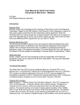
Download Case K44 Operator`s manual
Transcript
~/~ ~ -C11(' ~ H ROtARY MOWER K40,~ K46 Operator's Manual 9-51560 Written In Clear And Simple English 1\ \ J I Case A Tenneco Company r----. IF THIS MACHINE IS USED BY AN EMPLOYEE OR IS LOANED OR RENTED, MAKE ABSOLUTELY CERTAIN THAT THE OPERATOR(S), PRIOR TO OPERATING: 1. fS fNSTRUCTED fN SAFE AND PROPER USE. 2 . REVfEWS AND UNDERSTANDS THE MANUAL(S) PERTATNfNG TO THE I\1ACHfNE. 751253 BEFORE STARTING ENGINE STUDY OPERATOR'S MANUAL SAFETY MESSAGES READ ALL SAFETY SIGNS ON MACHINE CLEAR THE AREA OF OTHER PERSONS LEARN & PRACTICE SAFE USE OF CONTROLS BEFORE OPERATING I T IS YOUR RES PON SIBILITY T O UNDE RST AND AND FOL LO W MAN U F ACTURER'S INSTRU CTIONS ON M ACHINE OPERAT IO N . SERV IC E, AND TO O BSERVE P ERTINENT L AWS AND REGU L AT. IO NS . OPE RATOR AN D SERVICE MANUA LS MAY BE O BTAIN E D FROM YOUR E QUI PMENT DEA LER. SAFETY MESSAGES A h . . Regard your lotary mower as <J piece of power equipment anci be sure this manual is read and under stood by all who operate It. A A Maintain your tractor and I otal y mower In top operating condition. A A - 3 CAUTION: Fill gas tank out of doors and avoid spilling gasoline. Do not fill tank with gasoline while smoking or while engine IS running . CAUTION: Never allo w children or young teenagers to opel ate the tractor and rotary mower CAUTION: Unbalanced blades are a hazard and will cause premature wear and failure of bearings and spindles. If the blades cannot be balanced by resharpening, replace them with new ones . CAUTION: Never g-et 011 or off the tractor while the mowel IS running. , h. . . A A CAUTION: Give complete and undivided attention to the job at hand. - CAUTION: Stop engine, disengage attachment drive, set parking brake and remove key when tractor is unattended. A A rn CAUTION: Do not allow anyone other than the operator to ride on the tractor. m rn A CAUTION: Stop and inspect the mower for damage immediately af ter striking a foreign object and repair damage before restarting and operating the machine. A DANGER: Spinning Blade. Keep clear. Contact can injure. IMPORTANT: CAUTION: Disengage attachment drive lever, stop engine and remove key and spark plug wire(s) before making adjustments. CAUTION: Shut off engine, allow engine to cool and remove key and spark plug wire(s) before replacing mower drive belt. CAUTION: Disengaqe attachment drive cl utch when someone ap proaches or whenever the mower is being transported. CAUTION: Be sureyoll knowhow to ~top the tractol Jnd mower at il moments notice. WARNING: Improper operation of your tractor on hillsides and slopes can be dangerous. Avoid improper operation! Read and follow the in structions given in the section ti tled "Hillside Operation" in this manual before operating your trac tor. Always install new decals whenever the old decals are destroyed, lost, painted over or illegible . When individual parts are replaced that have decals attached, be sure to install a new decal with the new part. Replacement decals are a vailable from your Case dealer. -4 HILLSIDE (SLOPE) OPERATION Avoid operating tractor on hillsides and slopes. To mini· mize the possib ility of accidents while operating on hills and/or rough terrain, obey a combination of rules, prac· tices and good common sense. Read, Understand, Obey: Safety messages are found on the tractor and in the op erator's manuals. These l!ll:!.U be understood by the trac !QLfmerator to be of value. Be sure that these messages are studied before starting and/or operating the tractor by an operator not familiar with this particular tractor. These include: 1. Reading, understanding, and obeying all written safety messages appearing on decals on the mach ine and in operator's manuals. learn to OJ:1erate: Learn your tractors controls from decals on the tractor and from instructions in the operator's manual. Practice how to properly manipulate these controls. Practice must be done in a flat area, clear of obstacles and bystanders. Learn your tractors operating characteristics and limita tions. These include: 2. Learning from your operator's manual and carefully from EXPERIENCE how to operate your tractor cor rectly. Know your tractor's limitations. 3. Knowing the terrain on which you are operating your tractor. There are terrain conditions on which your tractor cannot be operated! a. amount of engine power available b. engine governor response 4 . Learning to expect changes in operating conditions. Adding or removing attachments or weight to your tractor will make your tractor perform differently. Rain, snow, loose gravel, wet grass, etc., change the tractive conditions of the terrain requiring changes in your operating technique or not to operate on that terrain. The following paragraphs will cover these practices one at a time. Read and study them. The examples provided are not all inclusive but will give you a firm understanding of the requ irements for avoid ing accidents wh ile operating your tractor. c. tractive abil ity d. steering characteristics e. braking characteristics f. movement of travel lever g. forward and reverse ground speeds h. speed of attachment lift I. and others Attempting any operation which approaches or exceeds the tractor's Iim;'tation is risking an accident. A tractor, the same as your model, passed a stability test at angles prescribed by ANSI B71.1 - 1972 and B71. 1 a 1974 (American National Standards Institute) . This test was made with a stationary tractor without mounted equipment and on a perfectly smooth and hard surface. This may not be representative of the conditions on which your tractor will operate. Know the Terrain: Know the terrain on which you are working. ,Find hidden obstaCles by walking through and inspecting the area prior to operating your tractor on it. Mark obstacles, such as, rocks, ruts or holes with a 6 ft . long pole and red flag and illY well clear of these obstacles when operating. Operate your tractor at a ground speed slow enough to in sure complete control at all times. THE OPERATOR IS THE SOLE JUDGE AS TO THE DEGREE OF SLOPE ON WHICH THIS TRACTOR CAN BE SAFELY OPERATED. IF IN DOUBT THAT THIS TRACTOR CAN BE SAFELY OPERATED ON A PAR TICULAR SLOPE, DO NOT OPERATE ON THAT SLOPE! COMMON SENSE MUST PREVAIL. Place the transmission in low range and regulate the travel control lever slowly and smooth Iy to mainta in th is safe speed . -5 Always drive in a forward direction when proceeding downhill. Never drive up a hill. If necessary, back up a hill to the desired position. Always back up loading ramps and tilt bed trailers. If necessary to turn while on a hill, always turn downward . Adding an attachment (weight) to the rear of the tractor reduces the weight on the front axle . Adding an attach ment (weight) to the front of the tractor reduces weight on the rear of the tractor. You must add counterweight to the front if a rear mounted attachment is installed. You must add counterweight to the rear if a front moun ted attachment is installed . Your judgement, based on operating experience is the final word in deciding if you should negotiate any given hill or slope. If you are in doubt about safety - STAY OFF THE SLOPE. Tractive conditions will vary with weather and terrain and equipment. Areas wet with dew, rain or snow will be more slippery than when dry. Areas covered with loose gravel are more slippery than firm dry ground. Greater stopping distances are required in these slippery areas. Under no circumstances should an inexperienced operator attempt to use your tractor on slopes or hillsides. You may encounter some terrain on which your tractor cannot be operated even if a different piece of equipment has operated there in the past. Spinning rear wheels tend to move the tractor sideways. The addition of tire chains will provide more traction to the rear wheels in the forward-reverse direction but less stability in the sideways direction. Chains will cause more abrupt starting and stopping. Learn to Compensate for Changes in Operating Condi tions: Adding or removing attachments or ballast (such as wheel weights or fluid) change the weight and weight distribu tion of your tractor and, therefore, change your tractors operating characteristics. The final word in safe tractor operation rests on your judgement. Be alert to these ch anges. Practice operati ng the tractor after each change has been made. If in doubt of your safey - STAY OFF TH E SLOPE . f -6 INTRODUCTION This operator's manual is for the Model K40, K44, and K46 rotary mower. This operator's manual includes: Read this manual before operating your rotary mower. See your J I Case dealer for parts or repairs. a. Safety Rules b. Installation Procedure c. Operating Procedure The words "Right, Left, Front and Rear" as used in this manual indicate directions when you are in the operator's seat in the normal operating position. d. Adjustments e. Maintenance ATTACHMENT APPLICATION CHART MODEL SIZE TRACTOR MODEL (Beginning with P.I.N. 9646800 ) K40 38" (965 mm) 210, 220, 222, 442 44" (1115 mm) 222,224,442,444,44~644,646,648 48" (1220 mm) 224,444,446,448,644,646,648 G K46 BELT APP LICATION CHART * TRACTOR MODEL BE LT PART NUMBER 210 All 220 Before P.I.N. 9656747 220 P.I.N . 9656747 and after 222 Before P.I.N. 9658189 222 P.I.N. 9658189 and after 224 All 442 All 444 Before P.I.N . 9661261 444 P.I.N. 9661261 and after 446,448 All 644 Before P.I.N. 9698343 644 P.I.N. 9698343 and after 646,648 All " C23358 C23807 C23358 C23807 C23358 C23358 C23809 C23809 C23359 C23359-t C23807 C23810 C23808 Belts included with your tractor . INSTALLATION 01\1 TRACTORS BEFORE PRODUCT IDENTIFICATION NUMBER 9646800 SPECIAL INFORMATION TRACTOR MODEL ALL Lift links included with tractor. NOTE: Part numbers can change. Dealer. -7 TRACTOR MODEL USE KIT 220, 222 442,444 H-38 H-39 See your J I Case OPERATING CONTROLS ATTACHMENT CLUTCH LEVER The rotary mower is started and stopped with the attach ment clutch lever. See your tractor operator's manual for correct use of your tractor controls . HEIGHT SELECTOR LEVER See your tractor operator's manual for correct use of your tractor controls . The cutting height is controlled by the height selector lever. ATTACHMENT LIFT LEVER The rotary mower is raised and lowered with the attach ment lift lever. TO INCREASE THE CUTTING HEIGHT : Disengage the pin and pull the height selector lever up. TO DECREASE THE CUTTING HEIGHT: Disengage the pin and push the height selector lever down. HYDRAULIC LIFT When mowing, put the attachment lift lever in the "LOWER" position until the lift arms are midway in the lift link slots. TRACTOR TRAVEL LEVER ATTACHMENT LIFT HIGH-LOW HEIGHT SELECTOR LEVER FIGURE 1 (MODEL 222 WITH MODEL K44 ROTARY MOWER) OPERATION 5. Get on and get off the tractor correctly. Never use the 1. See the "ADJUSTMENTS" and "MAINTENANCE" sections of this manual before operating your rotary mower. lawn mower frame for a step. 2. See your tractor operator's manual for correct use of you r tractor controls. A 3. Learn to operate the tractor and rotary mower in an area clear of persons and obstructions. 4 . Check the work area for obstructions . Remove the small obstructions. Mark the large obstructions so you can see them. Do not hit the large obstructions . -8 WARNING: Be sure that the at tachment drive clutch is off, the engine is shut off, the key removed and the blades have stopped spin ning before attempting to clean a plugged discharge chute . TO GET ON THE TRACTOR FROM THE RIGHT SIDE: A a. put your right foot on the right foot rest b. put your right hand on the steering wheel c. put your left hand on the seat back Be eel tJIIl whoever operdtes till' Illowel has I ead and undel stands the Safety Rules III the flOllt of this manual. 7 . Lower the lawnmower to the cutting position . Make sure the lift arms are located in the center of the slots in the lift links . This permits free movement of the lawnmower. d . swing your left leg between the steering wheel and seat TO GET ON THE TRACTOR FROM THE LEFT SIDE : a. put your left foot on the left foot rest b. put your left hand on the steering wheel c. put you r right hand on the seat back d. swing you r right leg between the steering wheel and seat On tractors with hydraulic Iift, do not put the attach · ment lift lever in the "FLOAT" position . Use the reverse procedure to get off the tractor. A CAUTION: Never get the tractol while the luniling 011 01 1ll0WCI off IS 6. Start the rotary mower by smoothly engag ing the at tachment clutch lever. MOWING CONDITIONS Mowing conditions can be different. You must use the correct operating methods according to the following chart : CONDITION METHOD 1. Short or thin grass . 1. a . move the height selector lever to the cutting height needed. b. move the throttle lever to a position between 3/4 and full throttle. c. adjust ground speed as needed. d. you may decrease engine speed or put the range se lector in the "HIGH" position if this doesn 't cause an overload to the engine. The engine will become too hot and the rotary mower will not work cor rectly if the engine is operated with an overload. -9 CONDITION METHOD 2. Long or thick grass. 2. a. move the height selector lever to the highest posi tion. b. increase engine speed to the "FULL THROTTLE" position . c. reduce ground speed. d. cut long or thick grass twice. e. operate with the chute facing the cut area. 3. Wet grass. 3. a. do not cut wet grass. 4. Rough terrain. 4. a. raise the mower into the transport position . b. put the gauge wheels in the "M" position . c. operate the mower in the transport position to keep the gauge wheels off the ground. d. reduce ground speed. 5. a. use the right side of the rotary mower. 5. Cu tting near objects. .:a.. "-...; '~ The cut material will be moved away from the object. 6. When grass will not be swept. 6. a. operate with chute facing the cut area. 7. When grass will be swept. 7. a. operate with chute facing the uncut area. b. the grass will be in one strip and can be removed with a sweeper. 8. turn the tractor so the wind will move grass away from 8. Wind. you. FIGURE 3 FIGURE 2 . 10 ADJUSTMENTS FIGURE 4 A 2. Reduce ground speed. CAUTION: Disengage attachment drive lever, stop engine and remove key and spark plug vvlre(s) before making adjustments. DRIVE BELT TENSION. (See Figure 5.) The belt tension is correct when the gap between spring coils is equivalent to one wire diameter. HEIGHT SELECTOR LEVER. (See Figure 4.) You can adjust the lawnmower height with the height selector lever. TO INCREASE BELT TENSION : Turn the adjusting han dle counterclockwise. TO CHANGE THE CUTTING HEIGHT: TO DECREASE BELT TENSION: Turn the adjusting handle clockwise. 1. Raise the lawnmower into the transport position. This will decrease the weight on the height selector lever. IMPORTANT: 2. Pull outward on the pin. 3. Move the lever up or down to the needed height. Check the belt tension after the first hour of use. Adjust the belt tension if necessary. Before each use, check the belt tension and adjust if necessary. 4. Push the pin into the hole selected. GAUGE WHEELS. (See Figure 4.) 1) WINO KEY CLOCKWISE By HAND AS FAR AS POSSIBLE AND PLACE ATTACHMENT DRIVE IN ENGAGEMENT POSITION SMOOTH TERRAIN DECK DRIVE 1. Always operate the rotary mower with the gauge wheels on the ground. Make sure all weight is off the lift links for the rotary mower. The lift links must move freely to cut level and even. PULLEY 2) INSTALL BELT OVER PULLEYS AND IDLER PULLE YS AS SHOWN OOUBLE CHECK THAT THE BELT IS PAOPERl Y SEATED IN EACH PULLEY WITH ONLY ONE 90 DE · GAEE TWIST BETWEEN SUCCEEDING PULLE YS 2. The gauge wheels must not contact the ground while the lawnmower is in the transport position. 3) W INO KEY COUNTER . CLOCKWISE UNTil GAP BETWEEN SPRING COilS SPRING IS EQUIVALENT TO SPRING WIRE DIAMETER IDLEA PULLEYS ROUGH TERRAIN EY ~LOOSEN ~ l5 1. Operate the rotary mower in the transport pOSitIOn TI GHTEN and with the height selector lever in the "M" position. This will keep the gauge wheels from contacting the ground. FIGURE 5 - 11 II 41 AT PERIODIC INTEA · VA lS RECHECK FOR CORRECT CLEARANCE BETWEEN COILS AND ADJUST AS REQUIRED 
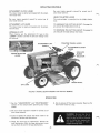
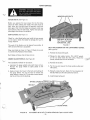
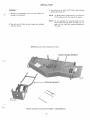
3. Measure the distance from the blade ends to the level surface. Make sure you measure as near the blade end as possible. LAWNMOWER FRONT TO REAR LEVEL. (See Figure 6.) Smooth cutting and minimum horsepower consumption are a result of a level rotary mower. The lawn mower is level when both front and rear blade measurements are the same. The front end may be 1/8" (3 mm) lower than the rear end. Never permit the rear end to be lower than the front end. This will cause more than normal power consumption. BEFORE STARTING THE PROCEDURE: 1. Put the tractor and rotary mower on a level surface, like a concrete floor. 2. Put the heightselector lever in the "M" position. LAWN MOWER SIDE TO SIDE LEVEL (See Figure 6.) I 3. Lower the lawnmower to the cutting position. Make sure the problem is not the air pressure in the tires. The air pressure in both tires must be correct and equal. TO RAISE THE FRONT OF THE LAWNMOWER: Lawn mower side to side level is adjusted at the factory. If additional adjustment is necessary: 1. Loosen the rear nuts that hold the leveler links. 2. Turn the two front nuts rearward an equal number of turns. 1. make sure the lawn mower is level "front to rear" TO LOWER THE FRONT OF THE LAWNMOWER: 2. move the tractor and lawn mower to a level surface 1. Loosen the front nuts that hold the leveler links. 3. move the height selector lever to the "M" position 2. Turn the two rear nuts forward an equal number of turns. 4. lower the lawn mower to the cutting position TO CHECK FOR LEVEL : 5. Ioosen the two bol ts that fasten the guage wheel car· rier to the lawn mower 1. Rotate the blades until they are parallel to the trac tor frame from front to rear. 6. raise or lower the carrier as required. Make the holes larger if additional adjustment is needed. 2. Make sure the nuts on the leveler links are tight. 7. tighten the bolts ADJUST NUTS REARWARD TO RAISE FRONT OF MOWER FIGURE 6 - 12 MAINTENANCE A CAUTION: Disengage attachment drive lever, stop engille and remove key and spark plug wlle(sl before making adjustments MOWER BLADE BOLTS BLADE BOLTS. (See Figure 7.1 Before you operate the lawn mower for the first time, check the bolts holding the blades. The bolts must be tight. After the first eight hours of operation, check the bolts again. Each time the blades are removed, install new lock washers under the bolt heads. Tighten the bolts and check again after 8 hours of operation . BE.NT BLADES. (See Figure 7.) Oleck for a bent blade before you install the lawn mower on the tractor. Check the blades for damage after you hit foreign material. TIPS MUST BE WITHIN 1/8" (3 mm) OF SAME HORIZONTAL LINE. FIGURE 7 The ends of the blades must be aligned horizontally. A 1/8" (3 mm) difference is acceptable. BElT REPLACEMENT ON THE lAWN MOWER CHASIS. (See Figure 8.) Align two blades as shown in Figure 7. Check all six ends in a similar way. Replace all bent blades. 1. Remove the chassis belt guard. Bent blades will leave strips of grass not cut. MOWER GAUGE WHEELS. (See Figure 8. ) 2. Release the idler pulley tension . Put a 9/16" wrench on the nut which holds the idler pulley. Rotate the wrench towards the front of the chassis. Two acceptable methods of lubrication : 3. Remove the old belt. a. lubricate the gauge wheels every eight hours of use . Remove the gauge lNheels to apply grease to the bushings. 4. Put the new belt around the three spindle pulleys and idler pulley. b. Apply oil every four hours to the bolts and bushings of the gauge wheels. You do not need to remove the gauge lNheels to apply oil. Tilt the lawn mower chassis. let the oil flow into the bushings. FIGURE 8 5. Manually rotate the belt. Check for free movement of the belt. Make sure the idler pulley has tension . 6. Install chassis bel t guard. K44 MOWER WITH BELT GUARD REMOVED FOR A CLEAR VIEW . 13· ( SHARP BLADES. (See Figure 9.) CLEANING THE LAWN MOWER CHASSIS Stop the engine. Wait for all motion to stop. Be careful while you check the lawn mower blades. After each job check for damage or blade wear. Large amounts of grass in the blade chassis will: A blade that is worn can give a rough cut and brown areas of grass can resul t. 2. cause an obstructi on 1. cause more than normal horsepower consumption 3. cause a bad cutting job See Figure 9 for the correct angle of the cutting edge. The cutting edge must be at least 3-1/2" (90 mm) long. 4. cause corrosion 5. damage bearings or seals ",;,.;:·>\7:;;;· ,~,;;~ lk5"itig::,~·· ¥:\.~ CORR ECT ANGL E OF SHAR PENED CUTTING EDGE 'ii' rn WRONG ANGLE TO SHAR PEN CUTTING EDGE DANGER: Spinning Blade. Keep clear. Contact can injure. FIGURE 9 Stop the engine. Wait for all motion to stop. Use cau tion when you check the lawn mower chassis. Periodical ly check and clean the chassis . Remove the grass wound between the blade mounting plates and spindle housings. NOTE: The K46 lawn mower blades have different lengths. The center blade is 1" (25 mm) shorter than the outsiqe blades. Make sure the shorter blade is installed on the center spindle. TRACTOR AND ENGINE MAINTENANCE Complete instructions for tractor and engine mainten ance are in your tractor operator's manual. Manually rotate the blades after installation. Check for correct clearance th rough one com plete turn. CHECK AND CLEAN DAILY: 1. Fins of the heat exchanger. After grinding a blade, check for balance . Use a balance tool as shown . A balanced blade will stay in a horizontal pos ition. 2. Air intake screen of the engine. 3. Air cleaner element. During dust or dry conditions use a precleaner. The pre cleaner fits over the air cleaner element and gives the ele ment a longer life. The precleaner can be washed with detergent and water. See Figure 11. PRECL~~,.~ FIGURE 10 CAUTION: Unbalanced blades are a hazard and will cause premature wear and failure of bearings and spindles. If the blades cannot be balanced by resharpening, replace them with new ones. FIGURE11 A TIRE AIR PRESSURE Keep the tires at the correct air pressures. See your trac tor operator's manual. - 14 INSTALLATION 3. Use cotter pins to fasten the lift links to the mounting bracket. See Figure 13. ASSEMBLY 1. Remove the components from the box. Check for damage or missing parts. NOTE: 2. The belt and lift links for your mower are included with your tractor. NOTE: Do not assemble the mounting bracket to the lawn mower chassis as shown in Figure 13. It is easier to first install the mounting bracket on the tractor. On Model 446 and 448 tractors, the offset lift link is fastened to the R. H. side of the tractor. NOTE: Belt and Iift links included with tractor. ~----- MOUNTING BRACKET / FIGURE 12 MODEL K44 ROTARY MOWER· DISASSEMBLED . 15 . MOUNTING BRACKET FIGURE 13 MODEL K44 ROTARY MOWER - ASSEMBLED NOTE: DO NOT ASSEMBLE MOUNTING BRACKET TO MOWER CHASSIS AS SHOWN. REFER TO STEP 3 - ASSEMBLY. INSTALLING 1. Put the tractor on a level surface like a concrete floor. TIGHTEN BE L T 2. Completely turn the belt adjuster handle counter clockwise. This will permit mounting clearance at the front axle. See Figure 14_ FIGURE 14 BELT ADJUSTMENT - 16 3. See Figure 15. Put the mounting bracket under the front of the tractor. Raise and install the mounting bracket on the mounting pins. Align the holes in the , mounting bracket with the "snap fast pins". Release the "snap fast pins" to hold in place. b. throught he front hole in the lift arm c. fasten on the outside with a safety pin On Model 446 and 448 tractors the left lift link is install ed using the above procedure. NOTE: Model 644, 646 and 648 tractors do not have "snap fast pins". Use two clevis pins and two safety pins. Use the offset lift link on the right side. To install: a. put lift link on outside of lift arm 4. Completely lower the lift arms on the tractor. On all models except the 446 and 448, put the lift links on the inside of the lift arm. See Figure 15. Put a plain washer on the clevis pins. From the inside install: b. install clevis pin from the inside c. fasten with washer and safety pin a. through the slot in the lift link 5. Raise the lift arms into the transport position. OFFSET LIFT LINK INSTALLATION FOR MODEL 446 AND 448 TRACTORS , TRACTOR ANCHOR PIN FIGURE 15 MOUNTING THE K44 MOWER MOUNTING BRACKET -17 . 6. Put the height selector lever in the "L" position. From the right side, sl ide the lawnmower under the tractor. Align the mounting tabs with the mounting bracket. A Raise the lawn mower to the "M" position. Lower the mounting bracket to the lawn mower chasis. See Figure 16. CAUTION: Shut off engine, allow engine to cool and remove key and spark plug wire(s) before replacing mower drive belt. 10. To install the belt: a. pull the belt up in front of the idler pulleys 7. Fasten the leveler links to the mounting bracket as shown in Figure 16. b. pull the belt up and between the heat exchanger and the fan 8. Connect the tab on the lawn mower to the mounting bracket. Use two clevis pins and safety pins. c. put the belt on the pulley of the attachment drive clutch NOTE: Manually lift the lawn mower to align the brack et and tab holes . d. turn the belt adjuster lever clockwise to allow the belt to go around the idler pulleys e. align the belt on the idler pulleys 9. Before you install the belt: f. put the belt on the pulley of the lawn mower a. stop the engine 11. Make sure the belt is correctly located on each pul· ley. See Figure 5. b. remove the ignition key 12. Turn the adjuster lever counterclockwise to tighten the belt. The belt tension is correct when the gap between spring coils is equivalent to one wire diameter. c. permit the engine to cool d. engage the attachment drive clutch (to allow belt to pass) IMPORTANT: e. raise the hood and remove the spark plug wire FIGURE 16 Before operating the lawn mower, read and follow the Adjustments and Main tenance sections of this manual. MOUNTING THE K44 MOWER CHASSIS - 18· TROUBLESHOOTING CHART LAWN MOWER NOT CUTTING EVEN OR LEAVING A STRIP OF GRASS POSSIBLE CAUSE COR RECTION 1. Obstruction in bottom of mower chassis. 1. Remove chassis and clean. 2. Blades not sharp . 2. Cutting edge must be sharp and at least 3-1/2" (89 mm) long. 3. Engine speed too slow. 3. Adjust engine speed to 3600 RPM. 4. Travel speed too fast. 4. Decrease travel speed. 5. Grass too long. 5. Cut twice. First at highest position then at needed height. 6. Drive or chassis belt slippage. 6. Check belts. Adjust tension or replace. 7. Attachment drive clutch slippage. 7. Adjust or repair attachment drive clutch. LAWN MOWER CUTS HIGH ON ONE SIDE POSSIBLE CAUSE CORRECTION 1. Adjust side to side level (first check for equal tire pres 1. Lawn mower chassis not level side to side. sure) . TOO MUCH POWER CONSUMPTION AND CUTS BADLY POSSIBLE CAUSE CORRECTION 1. BI ades not sharp. 1. Make blades sharp. 2. Lawn mower chassis not level front to rear. 2. Chassis must be level or no lower than 1/8" (3 mm) in front (first check air pressure in tires) . 3. Blades installed upside down . 4. Blade not straight. 3. Install correctly. Blades rotate counterclockwise. Cut ting edge must lead . 4 . Replace blade. CENTER BLADE ONL Y CUTTING POSSI BLE CAUSE CORRECTION 1. Chassis belt broken. 1. Replace belt. The J I Case Company reserves the right to make improvements in design or changes in specifications at any time without incurring any obligations to install them on units previously sold. • 11-81-0G-6500 Printed in U.S.A. - 19 "\