1
MasterAria
electronic controller
User manual
ENG
DISPOSAL
WARNINGS
CAREL bases the development of its products on decades of experience
in HVAC, on the continuous investments in technological innovations
to products, procedures and strict quality processes with in-circuit and
functional testing on 100% of its products, and on the most innovative
production technology available on the market. CAREL and its subsidiaries
nonetheless cannot guarantee that all the aspects of the product and the
software included with the product respond to the requirements of the final
application, despite the product being developed according to start-of-theart techniques. The customer (manufacturer, developer or installer of the final
equipment) accepts all liability and risk relating to the configuration of the
product in order to reach the expected results in relation to the specific final
installation and/or equipment. CAREL may, based on specific agreements, acts
as a consultant for the positive commissioning of the final unit/application,
however in no case does it accept liability for the correct operation of the final
equipment/system.
The CAREL product is a state-of-the-art product, whose operation is specified
in the technical documentation supplied with the product or can be
downloaded, even prior to purchase, from the website www.carel.com.
Each CAREL product, in relation to its advanced level of technology, requires
setup / configuration / programming / commissioning to be able to operate
in the best possible way for the specific application. The failure to complete
such operations, which are required/indicated in the user manual, may cause
the final product to malfunction; CAREL accepts no liability in such cases.
Only qualified personnel may install or carry out technical service on the
product.
The customer must only use the product in the manner described in the
documentation relating to the product.
In addition to observing any further warnings described in this manual, the
following warnings must be heeded for all CAREL products:
• prevent the electronic circuits from getting wet. Rain, humidity and all
types of liquids or condensate contain corrosive minerals that may damage
the electronic circuits. In any case, the product should be used or stored
in environments that comply with the temperature and humidity limits
specified in the manual;
• do not install the device in particularly hot environments. Too high
temperatures may reduce the life of electronic devices, damage them and
deform or melt the plastic parts. In any case, the product should be used
or stored in environments that comply with the temperature and humidity
limits specified in the manual;
• do not attempt to open the device in any way other than described in the
manual;
• do not drop, hit or shake the device, as the internal circuits and mechanisms
may be irreparably damaged;
• do not use corrosive chemicals, solvents or aggressive detergents to clean
the device;
• do not use the product for applications other than those specified in the
technical manual.
The product is made from metal parts and plastic parts.
In reference to European Union directive 2002/96/EC issued on 27 January
2003 and the related national legislation, please note that:
1. WEEE cannot be disposed of as municipal waste and such waste must be
collected and disposed of separately;
2. the public or private waste collection systems defined by local legislation
must be used. In addition, the equipment can be returned to the distributor
at the end of its working life when buying new equipment;
3. the equipment may contain hazardous substances: the improper use or
incorrect disposal of such may have negative effects on human health and
on the environment;
4. the symbol (crossed-out wheeled bin) shown on the product or on the
packaging and on the instruction sheet indicates that the equipment has
been introduced onto the market after 13 August 2005 and that it must
be disposed of separately;
5. in the event of illegal disposal of electrical and electronic waste, the
penalties are specified by local waste disposal legislation.
All of the above suggestions likewise apply to the controllers, serial boards,
programming keys or any other accessory in the CAREL product portfolio.
CAREL adopts a policy of continual development. Consequently, CAREL
reserves the right to make changes and improvements to any product
described in this document without prior warning.
The technical specifications shown in the manual may be changed without
prior warning.
The liability of CAREL in relation to its products is specified in the CAREL general
contract conditions, available on the website www.carel.com and/or by
specific agreements with customers; specifically, to the extent where allowed
by applicable legislation, in no case will CAREL, its employees or subsidiaries
be liable for any lost earnings or sales, losses of data and information, costs of
replacement goods or services, damage to things or people, downtime or any
direct, indirect, incidental, actual, punitive, exemplary, special or consequential
damage of any kind whatsoever, whether contractual, extra-contractual or
due to negligence, or any other liabilities deriving from the installation, use or
impossibility to use the product, even if CAREL or its subsidiaries are warned
of the possibility of such damage.
3
MasterAria +030220481 - rel. 1.0 - 12.11.2007
ENG
Contents
1. INTRODUCTION
7
2. USER
8
2.1 “Acqua” remote terminal ................................................................................. 8
2.2 Operating modes .............................................................................................. 8
2.3 Setting the time and On/Off times (timer) ............................................... 10
3. INSTALLATION
3.1
3.2
3.4
3.5
3.6
3.7
3.8
MasterAria and accessories ........................................................................... 11
Installation ........................................................................................................ 12
MasterAria panel wiring diagram ................................................................ 13
Connection diagrams .................................................................................... 14
“Acqua” remote terminal............................................................................... 15
Programming key (copy the configuration) ............................................. 16
Network connection ....................................................................................... 16
4. ADVANCED SETTINGS
4.1
4.2
4.3
4.3
4.4
4.5
11
17
Configuration.....................................................................................................17
Control algorithms ..........................................................................................23
Outlet limits ...................................................................................................... 31
Notes on settings via serial connection ....................................................34
Alarms................................................................................................................34
Table of parameters ........................................................................................36
5. SYSTEM DIAGRAMS
42
5.1 System 1 ...........................................................................................................42
5.2 System 2 ..........................................................................................................44
5.3 System 3 ..........................................................................................................46
6. NON-HYDRONIC SUPERVISORY SYSTEMS
48
7. TECHNICAL SPECS. AND PURCHASE CODES
48
7.1 MasterAria electrical panel .............................................................................48
7.2 Main control board..........................................................................................49
7.3 Expansion board with 2 x 0-10 Vdc outputs/2 relays ..............................50
7.4 Expansion board with 4 relays (accessory) ............................................... 51
7.5 Expansion board with 4 triacs (accessory) ................................................52
7.6 Expansion board with 2 triacs/2 relays (accessory) .................................53
7.7 “Acqua” remote terminal (accessory) .........................................................54
7.8 RS485 serial board (accessory) ....................................................................54
7.9 Codes .................................................................................................................55
7.10 Software revisions ..........................................................................................55
5
MasterAria +030220481 - rel. 1.0 - 12.11.2007
ENG
1. INTRODUCTION
main control board and expansion board selected with 2 modulating 0
to 10 Vdc outputs and 2 relay outputs, 4 triac outputs, 2 triac outputs and
2 relays, or 4 relay outputs and the “acqua” remote terminal.
The 3 outputs on the main board for controlling the fan can be used to
manage single-phase 3-speed fans (the first output controls the contactor
in the MasterAria electrical panel) and three-phase fans.
The system is simple to configure by setting the dipswitches on the main
control board and the parameters on the “acqua” remote terminal; this
can in fact be used to display the alarms, set the parameters and the on/
off time bands.
The possibility of configure the outputs and the availability of various
expansion boards means various types of loads can be controlled, such
as hot/cold water coil valves, heaters, hot and cold water signals to the
chiller/heat pump and boiler, outside damper, recirculation damper and
heat recovery unit damper.
The RS485 serial board (accessory) can be used to create custom
(PlantVisor) or open (Modbus®) supervisory systems.
Finally, the pCOWeb board (accessory) can be used to connect MasterAria
to a computer on an intranet, or alternatively to a save the variables and
graphs to a file that can be sent using Internet Explorer™.
Features of the MasterAria family:
• “Acqua” remote terminal with an elegant appearance, built-in room
•
•
•
•
temperature sensor and diversified access to the various functions
(values set using the front buttons, operating mode changed using
the side buttons);
Control board with high number of I/Os (5 digital inputs, 3 probes,
5 relay outputs and dipswitches for simple configuration by the
installer);
Custom connection to supervisory systems with the numerous
protocols supported (Modbus®, PlantVisor);
Parameter programming key (accessory);
Expansion board to control modulating 3-point or ON/OFF valves
(accessories)
MasterAria is a product designed for small air heater and air handling unit
(AHU) market, for both units with outside air only and with recirculation
or heat recovery units. It is used to manage a hot/cold water coil with
modulating valve and modulating outside air damper or alternatively two
coils with modulating valve and ON/OFF outside damper. The compact
electrical panel (IP54) contains the main control board, the expansion
board with 2 modulating 0 to 10 Vdc outputs and 2 relay outputs, the
circuit breaker and the fan protection and control contactor. Versions are
available for the control of single-phase and three-phase fan motors, with
the possibility to adjust the maximum cutoff current.
The product can also be supplied without the electrical panel, with the
7
MasterAria +030220481 - rel. 1.0 - 12.11.2007
ENG
2. USER
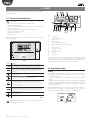
The user interface is the “acqua” remote terminal, featuring a user-friendly
liquid crystal display.
1
2
3
4
HR
2.1 “Acqua” remote terminal
ON
OFF
In summary:
13
AUTO
• built-in NTC sensor to control the room temperature;
• LCD with intuitive symbols;
• selection of the value displayed (temperature, set point, offset from
•
•
•
•
common set point);
selective keypad lock (limited functions for offices, hotels);
manual or automatic operation;
ON/OFF timer functions;
sleep function.
12
11 10
9
8
7
5
Fig. 2.b
Key:
1.
2.
3.
4.
5.
6.
7.
8.
9.
10.
11.
12.
13.
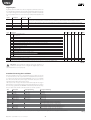
Below is a description of the terminal and the symbols shown on the
liquid crystal display:
HR
ON
OFF
AUTO
sleep function
limited keypad function
active alarm
display value
fan speed in automatic mode
fan speed setting indicator (min/med/max)
fan
dehumidification
automatic operation
cooling
heating with heater
heating
current time
Below is a description of all the operating modes available on MasterAria.
The device can in any case be reconfigured by the manufacturer of the
cooling/heating system or the installer (based on the features of the
system), and therefore some functions may be not available.
Fig. 2.a
butt. meaning
Air handling unit (AHU) ON/OFF. If the remote ON/OFF digital
input is available, the function of the button can be disabled.
Used to select the desired operating mode: cooling(snowflake),
heating (sun), dehumidification, ventilation, AUTOMATIC. If the
remote cooling/heating digital input is available, this button can
be disabled.
Pressing repeatedly sets the fan speed (min, med, max,
automatic=AUTO).
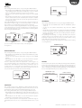
2.2 Operating modes
Cooling
Once having switched the device on, by pressing the ON/OFF button:
• Repeatedly press the MODE button until the cooling symbol
(snowflake) comes on.
• Set the set point (desired temperature) using the UP & DOWN
buttons.
• Repeatedly press the fan button to select the desired fan speed; if AUTO
mode is selected, the speed is decided by the electronic controller
based on the deviation from the set point (the greater the deviation,
the higher the speed).
Confirms to the changes made to the parameters.
Pressing once activates the sleep function, pressing again selects
the duration of the sleep function in hours (if more than three
seconds elapse from when the button was previously pressed, the
function is deactivated). After pressing 9 consecutive times, the
function is deactivated.
Holding the button sets the current time. Pressing once selects the
MasterAria ON time (changed using UP & DOWN), pressing again
selects the OFF time, and pressing a third time exits the timer
programming procedure.
If the COOL ENABLE function is active, the fan is started only if the coil
temperature is low enough, to avoid undesired flows of hot air. If this
condition is not satisfied, the cooling symbol (snowflake) flashes.
Increase value (UP)
Decrease value (DOWN)
Tab. 2.a
Important: The fan speed can only be selected using the fan
button if parameter 118 = 0.
MasterAria +030220481 - rel. 1.0 - 12.11.2007
6
Fig. 2.c
8
ENG
Heating
Once having switched the device on, by pressing the ON/OFF button:
• Repeatedly press the MODE button until the heating symbol only (sun)
or the heating symbol with heater, if installed (*), comes on. In the
latter case, the electric heater is also used as a source of heat;
• Set the set point (desired temperature) using the UP & DOWN
buttons;
• Repeatedly press the fan button to select the desired fan speed; if AUTO
mode is selected, the speed is decided by the electronic controller
based on the deviation from the set point (the greater the deviation,
the higher the speed).
If the HEAT ENABLE function is active, the fan is started only if the coil
temperature is high enough, to avoid undesired flows of cold air. If
this condition is not satisfied the heating symbol (sun) flashes.
If the electric heater is installed (signalled by the corresponding symbol
on the display), the fan continues operating for 20 seconds after it has
been deactivated. This time is also maintained when switching off the
device using the ON/OFF button.
with heater
without heater
Fig. 2.d
Fig. 2.e
Fig. 2.g
AUTOMATIC
Once having switched the device on, by pressing the ON/OFF button:
• Repeatedly press the MODE button until the AUTOMATIC symbol
comes on;
• Set the set point (desired temperature) using the UP & DOWN
buttons;
• Repeatedly press the fan button to select the desired fan speed; if AUTO
mode is selected, the speed is decided by the electronic controller
based on the deviation from the set point (the greater the deviation,
the higher the speed).
The operating mode (heating or cooling) is decided by the electronic
controller based on the deviation from the set point: if the room
temperature is higher than the set point, the controller activates cooling
mode, while if it is lower heating mode is activated.
The fan is started only if the coil temperature is suitable for the heating
or cooling functions.
(*): For the installation of the electric heater, see the paragraph on
“Configuration“.
AUTOMATIC mode
HR
ON
OFF
Dehumidification
AUTO
MAN
Once having switched the device on, by pressing the ON/OFF button:
• Repeatedly press the MODE button until the dehumidification symbol
(droplets) comes on;
• Set the set point (desired temperature) using the UP & DOWN
buttons;
• Repeatedly press the fan button to select the desired fan speed; if
AUTO mode is selected, the fan works at minimum speed.
The fan is started only if the coil temperature is low enough, so as
to avoid undesired flow of hot and humid air. If this condition is not
satisfied, the dehumidification symbol flashes. MasterAria starts in
cooling mode so as to bring the room temperature closer to the set
point (set point +3 °C) using the selected speed, and then runs fan on/
off cycles at minimum speed to decrease the humidity.
Fig. 2.h
Comfort
In some systems, the set point is decided by the manager of the installation;
in these cases, the user may increase or decrease the set point by up to 3
°C to compensate for different perception of the room temperature. The
value is changed by pressing the UP and DOWN buttons and is displayed
for 5 seconds, after which the previous display resumes.
AUTOMATIC mode
with comfort active
comfort variation
HR
HR
ON
OFF
ON
OFF
AUTO
MAN
Fig. 2.f
Fig. 2.i
AUTO
MAN
Fig. 2.j
Ventilation
This operating mode can be disabled by setting parameter 38=8. The
mode may be useful for circulating the air in the room. In this case, also set
the minimum opening of the outside damper (parameter 119> 0%).
Once having switched the device on, by pressing the ON/OFF button:
• Repeatedly press the MODE button so that only the fan symbol is on
(at the bottom of the display) together with the corresponding speed
bar.
• Repeatedly press the fan button to select the desired fan speed; if
AUTO mode is selected, the speed is set to medium.
The fan is started only if the room temperature is within the range of
temperatures from 15 to 35 °C, to avoid undesired flows of hot or cold
air.
9
MasterAria +030220481 - rel. 1.0 - 12.11.2007
ENG
Sleep
2.3 Setting the clock and On/Off times
(timer)
The sleep function is especially useful at night, when the decrease in
body temperature (due to sleep) changes the perception of the room
temperature.
In cooling mode the set point is increased by the value of the parameter
18 for the number of hours specified on the display, after which MasterAria
returns to the previous situation (the sleep function is cancelled).
In heating mode the set point is decreased by the value of parameter
19.
Setting the time
MasterAria offers the possibility to perform programmed starts and stops
if the room only needs to be air-conditioned at certain times of the day.
To be able to use these functions, the internal clock needs to be set with
the correct time, as shown below:
1. Hold the timer button for 5 seconds (the clock icon appears);
2. Set the time using the UP and DOWN buttons (the time flashes);
3. Confirm by pressing the SET button (the time is displayed steady).
To set the sleep function:
• Switch the device on using the ON/OFF button and select the
operating mode;
• Press the clear button repeatedly until setting the required number of
hours for the function.
To cancel this function, press the clear button again, after having waited
3 seconds from when the button was last pressed, or pressing the button
more than once until exceeding the maximum number of hours, that is,
9.
Sleep operation can be activated by a digital input that has been
configured accordingly. In this case, the function is called “economy” (see
the paragraph on “Digital inputs“).
1
2
3
HR
AUTO
MAN
Fig. 2.l
Important: In the event of power failures, the time returns to
12:00 and must be set again. The time display can be disabled by
setting parameter 38=128.
Remote off
Activated when dipswitch 3 = ON
When the remote off symbol (lock) is shown the operating mode is set to
AUTOMATIC (with heater, if installed) and the user can: switch the unit on/
off, modify the set point and set the fan speed; the other functions are not
available.
Setting the on and off times
• Press the TIMER button once;
• Set the required ON time with the UP and DOWN buttons (the time
flashes);
• Confirm the time with the “set“ button (the symbol is on steady and the
current time is displayed): the clock icon is shown with the text ON.
The OFF timer is set in the same way as the ON timer, with the difference
that the TIMER button must be pressed twice.
HR
ON
OFF
AUTO
MAN
Important: In the event of power failures, the timer values are
lost and must be reset.
Fig. 2.k
The ON/OFF timer functions remain active even after the corresponding
On/Off event has occurred; to disable these functions proceed as
follows:
• Press the timer button: once to disable the timer ON or twice to disable
the timer OFF (the time flashes);
• Press the “clear” button (the related symbol disappears).
Disabling the operating modes
Parameter 38 is used to reduce the number of operating modes available
on the “acqua” terminal. The setting is achieved by adding the values
shown below, each of which corresponds to disabling the corresponding
mode.
on time set: timer ON
off time set: timer OFF
HR
1
2
4
8
16
32
64
128
AUTOMATIC
cooling
dehumidification
ventilation
heating
autofan (see corresponding paragraph)
sleep
ON/OFF timer & time display
MasterAria +030220481 - rel. 1.0 - 12.11.2007
HR
ON
OFF
ON
OFF
AUTO
MAN
Fig. 2.m
AUTO
MAN
Fig. 2.n
Notes: the On/Off times can be set independently.
10
ENG
3. INSTALLATION
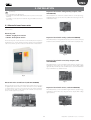
Expansion board with analogue/relay outputs (code
HYVC000V00)
In summary:
• easy configuration by dipswitches;
• possibility of control with intake/return probe or probe on the “acqua”
Allows MasterAria to control two actuators with 0 to 10 Vdc inputs (e.g.:
modulating valves, etc.) and control any additional loads using to the two
multifunction relays.
terminal;
• possibility to create supervisor networks using the RS485 serial board
(accessory).
3.1 MasterAria and accessories
Below is a description of the family of devices made up of MasterAria and
its accessories:
Fig. 3.c
Electrical panel
• CTEM7*: Single-phase version
• CTEDB*: Three-phase version
Expansion board with 4 relays (code HYVC000R00)
Allows MasterAria to manage ON/OFF actuators (valves, heaters, dampers)
and the hot and cold water signals to the chiller and heat pump/boiler).
The electrical panel contains the main control board plus the expansion
board with 2 x 0 to 10 Vdc outputs and 2 relay outputs. It is also fitted with
a disconnect switch, a power contactor for the fan and a circuit breaker
Fig. 3.d
Expansion board with 2 triac/relay outputs (code
HYVC000M00)
Allows MasterAria to control loads with a high number of operations (e.g.:
modulating 3 point valves, etc.) using the 2 triac outputs with voltage
signal (230 Vac) and directly control a 2 kW heater. A second multifunction
relay is available for any additional loads.
Fig. 3.a
Fig. 3.e
MasterAria main control board (code HYCT000000)
Manages the fan and controls the temperature. Allows the connection
of digital inputs for the remote control of functions such as ON/OFF,
cooling/heating, economy (see sleep function) etc. Fitted, using the
special accessory, with a serial port for the network connection of a
series of units (supervisory system).
Expansion board with 4 triacs (code HYVC000T00)
Allows MasterAria to control loads with a high number of operations (e.g.:
modulating 3 point valves, etc.) using the 4 triac outputs with voltage
signal (230 Vac).
Fig. 3.f
Fig. 3.b
11
MasterAria +030220481 - rel. 1.0 - 12.11.2007
ENG
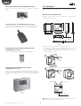
RS485 serial board (code HYSC00F0P0, accessory)
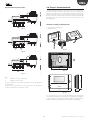
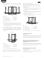
3.2 Installation
Used to create custom (PlantVisor) or open (Modbus®) supervisory
systems.
The electrical panel can be wall-mounted or installed in the air handling
unit.
Wall-mounting and dimensions:
Identify the correct position on the wall, drill 4 holes, according to the
drawing, and insert the plugs.
Fig. 3.g
Back
Front
240
Used to simply export the configuration of the parameters from one
MasterAria to another. PSOPZKEYA0 is the version with power supply.
235
218,5
Programming key (code PSOPZKEY00, accessory)
Ø3
162,5
200
87,3
19,3
90
78
190
Wall
mounting
21
8
Panel
mounting
Fig. 3.h
Fig. 3.k
Move the main switch on the panel to the OFF position and:
1. remove the top and bottom covers, and, without removing the front
cover, insert the screws and fasten the panel to the wall;
2. now unscrew the 4 inside screws and remove the front cover to access
to the electrical connections.
Adapter for MasterAria programming key (code
HYKA000000, accessory)
To be used together with the programming key PSOPZKEY00.
1
Fig. 3.i
“Acqua” LCD terminal for MasterAria (code
HYPA001000, accessory)
2
Allows the user to set the operation of MasterAria and display the alarms.
The LCD ensures straightforward and user-friendly operation. In addition,
it is fitted with an NTC sensor that can be used for room temperature
control.
power supply
fan, actuators
Fig. 3.j
probes, digital inputs
Fig. 3.l
Note: separate the power supply connections and the load cables
from the probe and digital input cables.
MasterAria +030220481 - rel. 1.0 - 12.11.2007
12
ENG
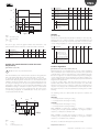
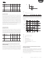
Structure
single-phase model
QS1
A1
235 mm
235 mm
three-phase model
QS1
A1
Key:
A1
A2
KR1-KM1
QS1
QF1
A2
QF1
Main control board
Expansion board
Contactor
Main switch
Circuit breaker
A2
QF1
KR1
Installing the boards and dimensions
The control kit consists of the main control board, an expansion board
and the “acqua” terminal.
KM1
195 mm
Fig. 3.m.a
Fig. 3.m.b
This is fastened to the electrical panel that controls the AHU using 4
plastic spacers (manufacturer RICHCO, code LCBS-8-01) inserted in the
holes on the four corners of the main control board..
5,6
7,1
195 mm
14,2
HYCT0*
5,6
37
2,8
20
12,7
65
85
95
10,2
2,5
150
Hole: Ø 4,75
board thickness: 1,6 mm
160
160
Fig. 3.n
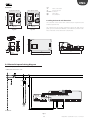
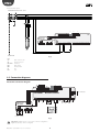
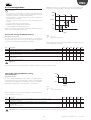
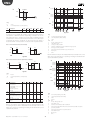
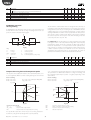
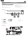
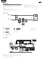
3.4 MasterAria panel wiring diagram
MasterAria single phase
POWER SUPPLY 1P+N+T 230V ~ 50 Hz
L
N
QS1
QF1
FU1
KR1
FLAP
EXP
IR
DIP
DI5
B1
B2
A1
B3
4
A2
HYCT000000
MasterAria controller
XP
HYVC000V00
valve board
GN NO4 GN NO5
NO6 NO6 NO7 NO7
L
L
N
N
N
NO3 NO2 NO1
GN Tx V+ GN Tx DI1 DI1 DI2 DI2 DI3 DI3 DI4 DI4
KR1
V1
FAN
MACHINE LIMIT
Fig. 3.o
13
MasterAria +030220481 - rel. 1.0 - 12.11.2007
ENG
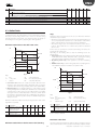
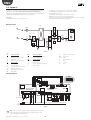
MasterAria three phase
POWER SUPPLY 3P+N+T 400V ~ 50 Hz
L1
L2
L3
N
QS1
QF1
FU1
FLAP
EXP
IR
DIP
B1
B2
A1
B3
5
3
1
DI5
HYVC000V00
valve board
6
4
2
KM1
GN NO4 GN NO5
A2
HYCT000000
L
NO6 NO6 NO7 NO7
L
N
MasterAria controller
N
N
NO3 NO2 NO1
GN Tx V+ GN Tx DI1 DI1 DI2 DI2 DI3 DI3 DI4 DI4
KM1
V1
FAN
.40
3
.40
3
MACHINE LIMIT
Fig. 3.p
Key:
A1
A2
KR1-KM1
QS1
QF1
V1
FU1
Main control board
Expansion board
Contactor
Main switch
Circuit breaker
Fan
Fuse
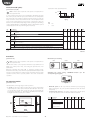
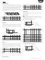
3.5 Connection diagrams
MasterAria connection diagram
FLAP
EXP
IR
DIP
DI5
B1
B2
B3
HYCT000000
L
HYVC000V00
valve board
GN NO4 GN NO5
L
N
N
N
NO3 NO2 NO1
HYPA0010*
valve
0...10 Vdc
Fig. 3.q
Important: Digital inputs 1 and 2 have a fixed configuration.
Digital inputs 3, 4, 5 can be configured.
MasterAria +030220481 - rel. 1.0 - 12.11.2007
GN Tx V+ GN Tx DI1 DI1 DI2 DI2 DI3 DI3 DI4 DI4
remote summer/
winter
OFF
N
NO6 NO6 NO7 NO7
contact contact
valve
0...10 Vdc
L
serial communication
MasterAria controller
14
SAFETY
ENG
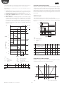
Expansion board (accessories)
3.6 “Acqua” remote terminal
Avoid installing the terminal in places where the room temperature
measurement may be altered: outside walls, near doors leading to the
outside, exposed to the sun, etc. (the terminal should be fastened to the
wall in a horizontal position so as to allow the recirculation of air through
the slits on the rear cover fastened to the wall). The terminal is fitted inside
the plastic case and is only accessible by removing the rear shell (see the
following figure).
DIP
DI5
B1
B2
B3
EXP
HYCT000000
HYVC000T00
SUPPLY
EXP
L
N No4
N No6
N No5
L
N
N
N
No3 No2 N
N No7
L
N
Terminal assembly and dimensions
1
1. bottom view: opening tab;
2. fastening holes.
Fig. 3.r.a
DIP
DI5
B1
B2
B3
EXP
HYCT000000
HYVC000M00
SUPPLY
EXP
2 A (res) 10 A (res)
L
N No4
N No5
L
N
N
N
No3 No2 N
No6 No6 No7 No7
L
1
N
1
2
Fig. 3.s.a
Fig. 3.r.b
DIP
DI5
B1
B2
B3
EXP
SUPPLY
EXP
L
N No4
N No5
2
HYCT000000
HYVC000R00
L
N
N
N
No3 No2 N
No6 No6 No7 No7
L
83
N
2
Fig. 3.s.b
Fig. 3.r.c
multifunction voltage output (triac)
multifunction relay output
86
Key:
1.
2.
For the configuration of the inputs and outputs, see the paragraph on
“Configuration“.
For the technical specifications of the components, see the chapter:
“Technical specifications and purchase codes”.
135
30
Fig. 3.s.c
For the connection see the connection diagram. If the temperature
measured by the built-in sensor needs to be corrected (due to installation
in a position that is not ideal) a fixed value in degrees centigrade can be
added or subtracted (see parameter 61 in the table of parameters).
15
MasterAria +030220481 - rel. 1.0 - 12.11.2007
ENG
3.7 Programming key (copy the
configuration)
Once having set the parameters (see the paragraph on “Configuration“),
the configuration can be quickly copied to other MasterAria controllers
using the programming key.
Proceed as follows:
1. switch off the previously programmed MasterAria (source);
2. set the dipswitches inside the programming key (underneath the
battery cover) to reading mode (dip 1= OFF, dip2= OFF );
3. insert the key in the 4-pin connector on the adapter, and connect the
8-wire cable supplied (see Fig. 3.t);
4. insert the 8-wire cable from the programming key adapter to the IR
connector on the board;
5. press the button. The red LED and then the green LED come on in
succession, if the operation has been completed successfully. Other
signals indicate problems (see the corresponding instruction sheet);
6. remove the key and the adapter; set the dipswitch to write mode (dip
1= OFF, dip2= ON ) and repeat steps 3, 4, 5, 6 to write the data to the
target MasterAria;
Important: to avoid excessively discharging the batteries in the
programming key, disconnect the normally closed digital inputs
on MasterAria. If this is not possible, use the key with the power supply.
The MasterAria parameters (source) can be copied to target devices with
the same or later software version.
Fig. 3.t
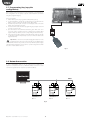
3.8 Network connection
A series of MasterAria devices can be connected via network to a
supervisor computer. In this case, a different address needs to be set for
each device (parameter 69= Supervisory network address).
RS485
MasterAria 1
P69 = 1
MasterAria 2
P69 = 2
Fig. 3.u
MasterAria +030220481 - rel. 1.0 - 12.11.2007
16
MasterAria 3
P69 = 3
ENG
4. ADVANCED SETTINGS
Outputs
In summary:
The triac output should be preferred over the relay output when the
actuator requires continuous switching (open/closed), as is the case with
modulating 3-point valves.
• fan speed control;
• algorithm to overcome the phenomenon of air stratification;
• antifreeze alarm management differentiated according to the type of
unit;
Important: Do not set outputs with option < = 6 and >6 at the
same time. This is because outputs with option > 6 automatically
imply the activation of the P+I algorithm, which is not suitable for the on/
off outputs: options 1,2,5,6.
In any case, the following outputs can be used: chiller activation signal,
boiler-heat pump activation signal and alarm. Only one output can be
set as a heater.
• manual operation: cooling, heating (optional heater management),
dehumidification, ventilation;
• automatic operation (optional heater management);
• room set point compensation with outside temperature reading;
• economy function: possibility to use a second set point if the
environment is not occupied (energy saving); the Economy function
is the same as sleep, with the difference that it is activated/deactivated
by digital input;
• control of ON/OFF or modulating valves and dampers: three-point or
with 0 to 10 Vdc input.
Example:
MasterAria with board with two 0 to 10 Vdc outputs and 2 relay outputs:
incorrect
P39 =13
P40 =21
P41 =6
P42 =24
MasterAria provides a number of additional functions compared to
traditional controllers: 2 digital inputs for remote ON/OFF and cooling/
heating management, 3 configurable digital inputs, 3 probes, 4
configurable outputs, 6 dipswitches for rapid customisation on site,
possibility of network connection for supervision.
MasterAria comes with a family of accessories (see the table of codes)
including: the “acqua” terminal (with built-in NTC sensor), the expansion
boards with 4 relay outputs, 4 triac outputs, 2 triac outputs and 2 relay
outputs, the RS485 serial board.
The following section shows, in sequence, the description of the
parameters, from the configuration of the I/O to the setting of the control
algorithms. The list of parameters is shown at the end of the section.
correct
P39 =13
P40 =21
P41 =18
P42 =24
Tab. 4.a.a
Important:
The outputs that are not used must be deactivated (option 0).
Table of outputs
Expansion
board
Control
board
Output Description
4.1 Configuration
To select the type of air handling unit (AHU)/air heater unit, proceed as
follows:
NO1
NO2
NO3
NO4
NO5
NO6
NO7
Voltage output (L) for minimum fan speed
Voltage output (L) for medium fan speed
Voltage output (L) for maximum fan speed
Multifunction output (see DIP4)
Multifunction output (see DIP4 & DIP5)
Multifunction output
Multifunction output
Assoc.
pars.
P39
P40
P41
P42
Tab. 4.a.b
The following summary table defines the type of output for each type of
expansion board available.
• connect the appropriate expansion board, if the board supplied is not
suitable for the actuators used (the board supplied with the MasterAria
electrical panel has two 0 to 10 Vdc outputs and two relay outputs, see
the wiring diagram);
• set the dipswitches on the main control board;
• select the type of predefined unit (parameter P91) that best suits the
application;
• on the “acqua” terminal, set the parameters for the inputs/outputs that
differ from the chosen configuration.
Important: if the AHU is OFF from digital input, the device cannot
be configured on the acqua terminal.
17
MasterAria +030220481 - rel. 1.0 - 12.11.2007
ENG
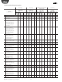
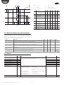
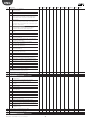
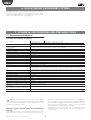
Summary table of MasterAria options
Setting
P39, P40, P41, P42
0
1
2
3
4
5
6
7
8
9
10
11
12
13
14
15
16
17
18
19
Output disabled
ON/OFF cold water valve
(norm. open)
ON/OFF hot water valve
(norm. open)
Chiller activation signal,
cold water request (norm.
open). Contact closed
with cold/hot water valve
or cold water valve only
active (open with valve
deactivated)
Boiler, heat pump
activation signal, hot
water request (normally
open). Contact closed
with cold/hot water valve
or hot water valve only
active (open with valve
deactivated)
ON/OFF hot/cold water
valve (normally open).
Activated with cooling/
heating request from
controller. Off when are
both deactivated
ON/OFF heater(normally
open) (set parameters P46
& P13)
Alarm (normally open)
DO NOT SELECT
3-point valve + (clockwise)
for cold water (hot/cold
water if dip4=OFF)*
3-point valve (anticlockwise) for cold
water (hot/cold water if
dip4=OFF)*
3-point valve + (clockwise)
for hot water (deactivated
if dip4=OFF) *
3-point valve (anticlockwise) for hot
water (deactivated if
dip4=OFF) *
Valve with 0 to 10 Vdc
input for cold water (hot/
cold water if dip4=OFF) *
Valve with 0 to 10 Vdc
input for hot water
(deactivated if dip4 =OFF)
*
DO NOT SELECT
DO NOT SELECT
0 to 10 Vdc output for
modulating heater control
(from external module).
Set parameters P111,
P117.*
Output (triac or relay) for
man. of ON/OFF heaters
(with hysteresis) on P+I. Set
parameters P111, P112.*
Open 3-point outside
damper*
Accessory
Accessory
Expansion board w/ 4 relays
HYVC000R00
Expansion board w/ 4 triacs
HYVC000T00
NO4 NO5
NO4
NO6 NO7
(volt. (volt.
(volt.
(relay) (relay)
relay) relay)
triac)
NO5
(volt.
triac)
NO6
(volt.
triac)
NO7
(volt.
triac)
Supplied with MasterAria
electrical panel
Expansion board w/ 0 to 10
Vdc + relays
HYVC000V00
NO4 NO5
NO6 NO7
(0-10 (0-10
(relay) (relay)
Vdc) Vdc)
Accessory
Expansion board w/ 2 triacs
+ 2 relays
HYVC000M00
NO4 NO5 NO6 NO7
(volt. (volt. (relay (relay
triac) triac) 2 A) 10 A)
√
√
√
√
√
√
√
√
√
√
√
√
√
√
√
√
√
√
√
√
√
√
√
√
√
√
√
√
√
√
√
√
√
√
√
√
√
√
√
√
√
√
√
√
√
√
√
√
√
√
√
√
√
√
√
√
√
√
√
√
√
√
√
√
√
√
√
√
√
√
√
√
√
√
√
√
√
√
√
√
√
√
√
√
√
√
√
√
√
√
√
√
√
√
√
√
√
√
√
√
√
√
√
√
√
√
√
√
√
√
√
√
√
√
√
√
√
√
√
√
√
√
√
√
√
√
√
√
MasterAria +030220481 - rel. 1.0 - 12.11.2007
√
√
√
√
√
√
√
√
√
√
18
√
√
√
√
√
√
√
√
ENG
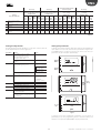
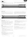
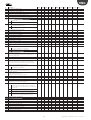
Accessory
Setting
P39, P40, P41, P42
Accessory
Expansion board w/ 4 relays
HYVC000R00
Expansion board w/ 4 triacs
HYVC000T00
NO4 NO5
NO4
NO6 NO7
(volt. (volt.
(volt.
(relay) (relay)
relay) relay)
triac)
Close 3-point outside
damper*
0 to 10 Vdc outside
21
damper
22 DO NOT SELECT
23 ON/OFF outside damper
√
ON/OFF recovery bypass
24
√
damper
(*) The P+I parameters need to be set
20
NO5
(volt.
triac)
NO6
(volt.
triac)
NO7
(volt.
triac)
√
√
√
√
Supplied with MasterAria
electrical panel
Expansion board w/ 0 to 10
Vdc + relays
HYVC000V00
NO4 NO5
NO6 NO7
(0-10 (0-10
(relay) (relay)
Vdc) Vdc)
√
Accessory
Expansion board w/ 2 triacs
+ 2 relays
HYVC000M00
NO4 NO5 NO6 NO7
(volt. (volt. (relay (relay
triac) triac) 2 A) 10 A)
√
√
√
√
√
√
√
√
√
√
√
√
√
√
√
√
√
√
√
√
√
√
√
√
√
√
√
Tab. 4.a.c
Setting the dipswitches
Setting the parameters
The default setting of all the dipswitches on the main control board is off.
Set the dipswitches based on the application.
To display and set the parameters, with device OFF, press the “MODE“ and
“clear“ buttons for 5 seconds and enter the password 22 using the “UP”
and “DOWN” buttons. Confirm by pressing “set“. This accesses the user
parameters only (U in the table of parameters).
Dipswitch
1
2
3
Setting
ON = enable heat/cool enable
functions (probe B2 on coil).
Probe B3 enabled only when
DIP1=ON e DIP4= ON;
OFF = heat/cool enable function
disabled
ON = enable digital input 2 for
cooling/heating changeover
Notes
HR
ON
OFF
AUTO
MAN
for operation of the
function see par. P56:
0 N.C.=Heating,
N.O.=Cooling
1 N.C.=Cooling,
N.O.=Heating
OFF = disable digital input 2 for
cooling/heating changeover
ON = remote lock active
HR
4
5
6
functions disabled:
ON/OFF timer, Sleep.
AUTOMATIC
operation override
HR
ON
OFF
AUTO
MAN
OFF = remote lock not active
ON = AHU with 2 water coils
OFF = AHU with 1 water coil
ON = electric heater fitted
OFF = electric heater not fitted
ON = control probe is probe on
“acqua” terminal (BT)
OFF = control probe chosen from B1,
B2 or B3 (must also correspond to P15,
P16 or P17=5)
HR
Tab. 4.b
HR
ON
OFF
AUTO
MAN
Fig. 4.a
To display and set the manufacturer parameters (F in the table of
parameters), access the programming menu as described above, and
enter the second password (PASSWORD = 66) for parameter P92.
19
MasterAria +030220481 - rel. 1.0 - 12.11.2007
ENG
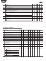
Automatic configuration of the inputs/outputs and type
of unit (parameter 91)
the antifreeze alarm is active the controller stops the fan and switches off
the optional electric heater.
To simplify configuration, one of the three automatic configurations can
be used (columns “Def1, 2, 3” in the table of parameters):
• Switch the device off by pressing the ON/OFF button;
• Set parameter 91 according to the values shown in the table below.
P124=1 AHU with recirculation
NO2
NO3
P91=44
AHU 100%
outside air
0-10 V valves
ON/OFF
Cooling/Heating
Serious alarm
Antifreeze alarm
Filter alarm
Outlet temperature
Heating coil
temperature
Outside
temperature
Single-speed outlet
fan
Disabled
Disabled
NO4
Cool valve
NO5
Heat valve
NO6
Outside damper
NO7
Disabled
Main board
Inputs &
Outputs
ID1
ID2
ID3
ID4
ID5
B1
B2
B3
Expansion board
NO1
P91=45
AHU with
recirculation
0-10 V valves
ON/OFF
Cooling/Heating
Serious alarm
Antifreeze alarm
Filter alarm
Outlet temperature
Heating/cooling
coil temperature
Outside
temperature
Single-speed outlet
fan
Disabled
Disabled
Heating / cooling
valve
P91=46
AHU with
recirculation
3-point valves
ON/OFF
Cooling/Heating
Serious alarm
Antifreeze alarm
Filter alarm
Outlet temperature
Heating coil
temperature
Outside
temperature
Single-speed outlet
fan
Disabled
Disabled
Open heating /
cooling valve
Close heating /
Outside air damper
cooling valve
Open outside air
Electric heater
damper
Close outside air
Bypass damper
damper
Tab. 4.c
Fig. 4.b.b
In this case, the AHU, as well as taking in air from the outside, recirculated
the air in the environment. The antifreeze function does not stop the fan
and, if an electric heater is fitted, this is not switched off.
Important:
The incorrect configuration of this parameter may cause damage
to the AHU!
Configuration of an AHU with heating/cooling coil only
(dipswitch 4 = OFF)
- Configuration with P91=45
MasterAria does not distinguish between coils for heating or cooling only
and mixed coils.
The distinction is made by the user, by setting the proportional bands
accordingly.
Note:
• The configurations corresponding to P91 = 44 and P91 = 45
require the expansion board with two 0 to 10 Vdc outputs (standard in
the MasterAria electrical panel), while the configuration corresponding
to P91 = 46 requires the expansion board with 4 triacs.
• Check that the corresponding inputs and outputs are enabled by
dipswitch. For example, once having set P91=44, check that dipswitch
4=ON (see the previous paragraph).
• Once parameter 91 has been set, the individual settings for the specific
application can be changed using the parameters corresponding to
the inputs/outputs (see the following paragraphs).
Par
39
40
41
42
Identifying/setting the model of unit (parameter 124)
Once automatic configuration has been completed, make sure that
MasterAria recognises the type of AHU being managed.
Description
Def2
Configuration of output NO4 13 = Valve with 0 to 10 Vdc input for
cold water (hot/cold water if dip4 =
OFF)
Configuration of output NO5 21 = 0 to 10 Vdc outside damper
(see P39)
Configuration of output NO6 18 = Output (triac or relay) for man. of
(see P39)
ON/OFF heaters (with hysteresis) on
P+I. Set parameters P111, P112.
Configuration of output NO7 24 = ON/OFF recovery bypass damper
(see P39)
Tab. 4.d.a
If a modulating valve is used, operation is established by the parameters
relating to the proportional bands.
The main setting involves the type of AHU:
• 100% outside air;
• recirculation.
In any case, dipswitch 4 must be OFF.
This is set using parameter P124:
P124=0 AHU 100% outside air
Coil model
Heating/Cooling
Heating only
Cooling only
Parameters
P115=xx / P116=xx
P115=0 / P116=xx
P115=xx / P116=0
Tab. 4.d.b
Par Description
Proportional band for
115
cooling valve
Proportional band for
116
heating valve
Fig. 4.b.a
The AHU with 100% outside air has just one air inlet, that is, from the
outside, and the air in the environment is no recirculated. In this case, when
MasterAria +030220481 - rel. 1.0 - 12.11.2007
20
Def1 Def2 Def3 Min Max UOM
40
40
40
0
255 °C /10
40
40
40
0
255 °C /10
ENG
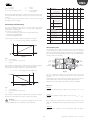
Configuration with electric heater
Recommended configuration
MasterAria can manage an electric heater with ON/OFF or proportional
0 to 10 Vdc control.
probe
B2
B3
Intake-return probe/
Outside probe
(compensation)
Heating coil probe
Cooling coil probe
BT
Probe on terminal
B1
For configuration:
1. dipswitch 4 = OFF, if a 0 to 10 Vdc signal is used (AHU with 1 coil only,
so the other output, NO4 or NO5, is not occupied);
2. dipswitch 5 = ON and configure the output with the parameters P39,
P40, P41, P42.
3. Press the MODE button until the display shows the heater icon.
Fig. 4.c
Important:
Outputs NO4 and NO5 are available for the modulating 0 to 10
Vdc heaters. Outputs NO6 and NO7 are available for ON/OFF heaters and
have voltage-free contacts.
Important:
During the antifreeze alarm, only in the case of AHUs with
recirculation, the heater remains on until the temperature returns to
normal values. This applies to the modulating 0 to 10 Vdc (P39=17) or
ON/OFF heater (P39=18), but not the ON/OFF heater with option P39=6.
associated
parameters
description
notes
When DIP6 OFF
P22, P58, P59,
& P22=0: room
P60
control probe.
P62, P63
P64, P65
When DIP6 ON =
P61
room cont. probe.
Tab. 4.e.a
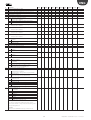
Prog Description
Def1 Def2 Def3
7
7
7
15
Function of probe B1
0 use defined by
dipswitch 6 & P22
1 probe disabled
2 heating/cooling coil
probe
3 cooling coil probe
4 heating coil probe
5 control probe
(intake/return)
6 outside probe
7 outlet probe
Min Max UM
0
7
---
16
17
22
Function of probe B2
(see P15)
Function of probe B3
(see P15)
Select optional
compensation probe
4
2
2
4
7
---
6
6
6
0
7
---
0
0
0
0
2
---
0
0
0
-99
127
°C/10
0
0
0
-99
127
°C/10
0
0
0
-99
127
°C/10
-30
-30
-30
-99
127
°C/10
0
0
0
-99
127
°C/10
0
0
0
-99
127
°C/10
0
0
0
-99
127
°C/10
0
0
0
-99
127
°C/10
0 Compensation
disabled
1 Compensation
enabled on
B1 = outside probe
2 Compensation
enabled on
B3 = outside probe
Selecting the electric heater
ON/OFF heater
There are 2 possibilities:
• set P39=18 (or P40, P41, P42)
Also set P111 (heater activation delta from set point) and P112
(hysteresis);
• set P41=6 (or P42)
58
Also set P46 (heater activation delta from set point) and P13
(hysteresis).
59
Modulating heater
60
• Set P39 = 17 (or P40 =17);
• Set P111 = heater activation delta and P117 = heater proportional
61
band.
62
63
64
Probes
65
The reading of the probes is affected by their position due to the
phenomenon of air stratification. To overcome this problem, offsets can be
specified depending on the operating mode (heating or cooling). Faults
with the control probe or the probe on one of the two heat exchangers
cause the fan to stop and the valve to close. The control probe is selected
by dipswitch.
It must be remembered that MasterAria performs control based on
the room temperature (intake/return probe or sensor on the “acqua”
terminal).
probe B1 offset in
cooling
probe B1 offset in
heating
probe B1 offset in
AUTOMATIC
probe BT offset from
terminal
probe B2 offset in
cooling
probe B2 offset in
heating
probe B3 offset in
cooling
probe B3 offset in
heating
Tab. 4.e.b
CTA
M
R
Fig. 4.d
Key:
AHU air handling unit
M
outlet
21
R
intake/return
MasterAria +030220481 - rel. 1.0 - 12.11.2007
ENG
Digital inputs
Digital inputs DI1 and DI2 have a fixed configuration, while the others can
be configured by parameter. The off status of digital input DI1 has priority
over any incoming serial communication signals, so that the user (directly
in contact with the flow of cold or hot air) can switch the MasterAria unit
off.
Input
DI1
Description
ON/OFF input
DI2
DI3
DI4
DI5
cooling/heating
multifunction
multifunction
multifunction
Ass. pars.
Notes
when the input is closed the unit is switched to OFF status (even when there is no network connection). When
switching OFF->ON, MasterAria is started however it can then be switched off from the terminal or via serial
connection. In OFF status, the valve is closed and the fan is off (after any extra flush cycles required for the heater)
Enabled when DIP2= ON
P43
P44
P45
Tab. 4.f.a
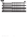
Prog Description
43
Configuration of digital input 3
0
input disabled
1
economy (norm. open) (*)
2
window alarm (norm. open): stops the fan and closes the valve
3
DO NOT SELECT
4
DO NOT SELECT
5
local stop (generic alarm, norm. open): stops the fan and closes the valve
6
economy (norm.closed)
7
window alarm (norm. closed)
8
DO NOT SELECT
9
DO NOT SELECT
10 local stop (generic alarm, normally closed): stops the fan and closes the valve
11 enable antifreeze by time (normally open)
12 enable antifreeze by time (normally closed)
13 dirty filter alarm from differential pressure switch (normally open)
14 dirty filter alarm from differential pressure switch (normally closed)
Def1 Def2 Def3 Min
10
10
10
0
Max
14
UOM
---
44
45
12
14
14
14
-----
Configuration of digital input 4 (see P43)
Configuration of digital input 5 (see P43)
12
14
12
14
0
0
(*) the “economy” function corresponds to the “sleep” function, however is activated by digital input.
Tab. 4.f.b
Important: avoid parameter settings that create situations of
conflict (for example, do not configure two digital inputs on the
same MasterAria as economy inputs).
Procedure for testing the installation
Once the installation has been completed, the test procedure can be run
to check the devices. The “acqua” terminal is required for these functions.
To enter test mode press the UP and DOWN buttons for 10 seconds with
the unit connected to the power supply and in OFF status; the event is
signalled by the buzzer, which emits a beep.
The test proceeds in steps, indicated on the terminal by the message “L”
followed by an incremental number; pressing the UP button proceeds to
the next step (signalled by the BEEPING of the buzzer). After the last step,
the procedure ends and the controller returns to normal operation.
step
part tested
message flashing
message not flashing
“L01”
probe B1
probe error
probe Ok
“L02”
probe B2
probe error
probe Ok
“L03”
probe B3
probe error
probe Ok
“L04”
digital input 1
input open
input closed
“L05”
digital input 2
input open
input closed
“L06”
digital input 3
input open
input closed
“L07”
digital input 4
input open
input closed
“L08”
digital input 5
input open
input closed
“L09”
fan
started at minimum speed, no internal test
“L10”
fan
started at medium speed, no internal test
“L11”
fan
started at maximum speed, no internal test
“L12”
output NO4
relay activated, voltage present (L). No internal test
“L13”
output NO5
relay activated, voltage present (L). No internal test
“L14”
output NO6
relay activated, contact closed. No internal test
“L15”
output NO7
relay activated, contact closed. No internal test
During operation (and during the test procedure), the device may generate alarm signals, which are displayed on the terminal.
Tab. 4.g
MasterAria +030220481 - rel. 1.0 - 12.11.2007
22
ENG
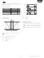
DIPSWITCH1 must be set to ON. The fan speed allowed (limiting the
request by the control algorithm) is described in the following graph.
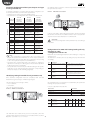
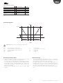
4.2 Control algorithms
In summary
FAN
• general functions: Heat enable, Cool enable, Flush, Extra Flush, P+I
•
•
•
•
•
temperature control, Freecooling, Freeheating, outlet limit control, fan
management, Autofan or continuous fan operation.
manual operation: cooling, heating (optional heater management),
dehumidification, ventilation;
automatic operation: heating (optional heater management) and
cooling;
set point compensation using outside probe;
On/Off timer (1 time band) and “sleep” function;
control of ON/OFF or modulating actuators.
P10
max.
P11
P12
medium
P13
min.
Below is a description of the operation of MasterAria, divided into general
functions, manual and automatic functions.
P13
OFF
P13
TB (°C)
Fig. 4.e
Heat enable (heating/AUTOMATIC heating)
Key
FAN
TB
(parameters 10,11,12,13)
In order to avoid undesired flows of cold air, the fan is only operated if
the temperature of the main coil (e.g. probe B2) is high enough. If this
condition is not satisfied the heating symbol (sun) flashes.
Par.
P10
P11
P12
P13
P55
fan speed
heating coil temperature
When reaching the set point, the hot/cold water or hot water valve only
is closed and the fan is stopped.
Description
Temperature to enable minimum fan speed in heating/AUTOMATIC heating
Temperature to enable medium fan speed in heating/ AUTOMATIC heating
Temperature to enable maximum fan speed in heating/AUTOMATIC heating
-Hysteresis to enable fan in heating/AUTOMATIC heating, cooling, AUTOMATIC cooling
-Heater hysteresis (P39=6)
Enable cooling & heating symbols in AUTOMATIC
0= symbols off
1= symbols on when called
Def1
29
33
37
10
Def2
29
33
37
10
Def3
29
33
37
10
Min
0
0
0
0
Max
255
255
255
255
UOM
°C
°C
°C
°C/10
0
0
0
0
1
---
Tab. 4.h.1
Important:
The heat enable function must be disabled if modulating actuators are used (0 to 10 Vdc or 3-point).
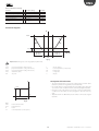
Cool enable (cooling/AUTOMATIC cooling,
dehumidification)
FAN
(parameters 13,14)
ON
In order to avoid undesired flows of hot air, the fan is operated only if the
temperature of the coil is low enough. If this condition is not satisfied the
cooling symbol (snowflake) flashes. DIPSWITCH1 must be set to ON. The
fan speed is managed by the control algorithms or set manually.
OFF
P14
TB (°C)
P13
Fig. 4.f
Key
FAN
TB
fan
cooling coil temperature
When reaching the set point, the hot/cold water or cold water valve only
is closed and the fan is stopped.
Par.
13
14
55
Description
- Hysteresis to enable fan in heating/AUTOMATIC heating, cooling, AUTOMATIC cooling
- Heater hysteresis (P39=6)
Temperature to enable fan in cooling/ AUTOMATIC cooling e dehumidification
Enable cooling & heating symbols in AUTOMATIC
0= symbols off
1= symbols on when called
Def1 Def2 Def3 Min
10
10
10
0
Max
255
UOM
°C/10
21
0
255
1
°C
---
21
0
21
0
0
0
Tab. 4.h.2
Important: The cool enable function must be disabled if modulating actuators are used (0 to 10 Vdc or 3-point).
23
MasterAria +030220481 - rel. 1.0 - 12.11.2007
ENG
Flush (fan on/off cycles)
equal to the value of parameter P32.
(parameters 32,33,34)
Note: Function active only if the control probe is not probe BT on
the “acqua” terminal.
FAN
min.
OFF
To overcome the phenomenon of air stratification, MasterAria operates
fan on/off cycles at minimum speed, even when the room temperature
has reached the set point (the local/hot/cold valve remains closed). This
helps ensure the correct measurement of the room temperature if the
sensor on the acqua terminal is not used (e.g.: control probe = B1). The
behaviour can be modified depending on the operating mode: heating,
cooling, dehumidification or AUTOMATIC. The fan is started after a period
of inactivity (due to the set point having been reached),
P33
P32
P32
P33
t
Fig. 4.g
Key
FAN
t
fan
time
Par.
32
Description
Flush off time
0
Disabled
>0
Fan off time
Def1 Def2 Def3 Min
2
2
2
0
Max
255
UOM
min
33
Flush on time
90
90
90
0
255
s
0
0
0
0
3
---
0
>0
34
Disabled
Fan on time
Flush mode
0
1
2
3
Function disabled
Flush function active in cooling, dehumidification & AUTOMATIC
Flush function active in heating & AUTOMATIC OFF(*)
Flush function active in heating, cooling, dehumidification & AUTOMATIC OFF(*)
AUTOMATIC OFF(*)= unit in automatic mode and off because the temperature measured by the control probe is inside the dead band (P109) around the set
point
Tab. 4.h.3
Extra Flush
Manual fan speed setting
(parameter 35)
min.
Note: Function active only if the control probe is not probe BT on
the “acqua” terminal.
This function ensures correct operation when the acqua terminal is not
fitted (e.g.: control probe = B1), overcoming the phenomenon of air
stratification.
Whenever switching from OFF->ON or changing operating mode,
MasterAria runs a fan cycle at minimum speed (for the time P35) to make
sure the room temperature is uniform. At the end of this interval, normal
operation resumes. This is especially useful in the event of automatic
operation.
med.
max.
Fig. 4.i.a
Automatic fan speed setting –AUTOFAN function (see the
corresponding paragraph)
AUTO
Fan operating modes
Fig. 4.i.b
(parameter 118)
The MasterAria can manage 3 types of fan operation:
• 3 speed: the fan stops when reaching the set point, (temperature
measured by the control probe inside the dead band). In this mode,
one of the three speeds (min., med., max.) can be set manually, by
pressing the fan button, or alternatively AUTOFAN, with automatic
management of the speed by the controller.
• Minimum speed: the fan only works at minimum speed, stopping
when reaching the set point (control temperature inside the dead
band, P109).
• Constant single speed: fan operating continuously at single speed,
except in the event of alarms or when the AHU is shut down.
Par Description
118 Fan mode
0 3 speed
1 minimum speed
2 continuous singlespeed (normally
used for AHUs)
Def1 Def2 Def3
2
2
2
Min
0
Max
2
U.M
---
Tab. 4.h.4
Fig. 4.h
MasterAria +030220481 - rel. 1.0 - 12.11.2007
24
ENG
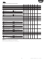
Par Description
07 Medium speed delta in
Auto Fan
08 Maximum speed delta in
Auto Fan
09 Fan speed hysteresis in
Auto Fan
118 Fan mode
0 3 speed
1 minimum speed
2 continuous singlespeed (normally used
for AHUs)
ON
CTA
OFF
t
ON
AL
OFF
t
ON
FAN
Def1 Def2 Def3 Min
7
7
7
0
Max
255
U.M
°C/10
7
7
7
0
255
°C/10
5
5
5
0
255
°C/10
2
2
2
0
2
---
OFF
Tab. 4.h.6
P35
t
P48
Fig. 4.i.c
Key:
AHU
AL
FAN
t
Comfort
(parameter 36)
Air Handling Unit
shutdown alarm
fan
time
This function, if activated by P36, disables modification of the set point,
allowing just a ±3 °C offset (in heating, cooling, dehumidification and
AUTOMATIC mode). The set point can be set by serial connection (see the
corresponding paragraph) or on the “acqua” terminal, for parameter P01.
The part in grey of the fan graph indicates that extra flush is only
performed if the electric heater was on before the AHU is shut down.
Prog Description
35
Flush time when
changing mode
48
Extra flush time with
heater
Def1 Def2 Def3 Min
30
30
30
0
Max
255
UOM
s
20
255
s
20
20
0
Par Description
Def1 Def2 Def3 Min
0
0
0
0
36 Select AUTOMATIC with
set point or Comfort
0 Comfort function
disabled (set point
P01 can be changed
from “acqua” terminal)
1 Enable Comfort (only
± 3°C change in set
point from P01)
Tab. 4.h.5
Autofan (fan speed selection based on the room
temperature)
Max
1
UOM
---
P and P+I algorithm
(parameters 7,8,9,118)
(parameters 110,111,113,114,115,116,117)
Note: Function only active when P118=0
MasterAria features a P+I algorithm that is used to control modulating
valves and dampers (0 to 10 Vdc and 3 point). Control can be performed
on the BT probe on the “acqua” terminal or on the intake/return probe
that can be assigned to one of the three MasterAria probes, by setting the
corresponding parameter. The P+I algorithm is activated by enabling one
of the modulating valve outputs and setting the proportional band and
integration time parameters.
To start an actuator with a delay from the previous device, use the
activation delta, which defines the point of activation of a device with
reference to the previous. For example, to activate the cold water valve at
set point + 4°C, simply set the cold water valve activation delta, P113=40
(the unit of measure is °C/10). The parameters for heating have a similar
meaning.
From the hardware point of view, the three speeds are managed by the
three outputs NO1, NO2, NO3 on the MasterAria main control board.
To activate the Autofan function, press the fan button on the “acqua”
terminal until displaying AUTO next the fan icon. The Autofan function
establishes the fan speed when there is no manual setting by the user.
In cooling and heating mode, the speed is higher the further the room
temperature is away from the set point (including AUTOMATIC cooling,
AUTOMATIC heating). In ventilation mode, the speed is constant at the
average value for the range set by parameters P30, P31, P06 (see the
corresponding paragraph). In dehumidification mode, the speed is
constant at the minimum value.
The following events are defined, with the respective conditions for
activation:
H
OPENING:
• room temperature increasing in cooling
• room temperature decreasing in heating
C
set point
max.
medium
P09
P09
P09
P09
min.
OFF
P08
CLOSING:
• room temperature decreasing in cooling
• room temperature increasing in heating
P09
P09
P07
When OPENING in heating, the activation sequence is: 1-Damper,
2-Heating valve, 3-Heater (*). When OPENING in cooling the activation
sequence is: 1-Damper, 2-Cold water valve
P07
P08
TA (°C)
When CLOSING in heating the activation sequence is: 1-Heater(*)
2-Heating valve, 3-Damper. When CLOSING in cooling the activation
sequence is: 1-Cold water valve, 2-Damper.
Fig. 4.j
Key
H
C
TA
This can be considered a LIFO sequence (Last In, First Out)
heating
cooling
room temperature (°C)
Proportional control - P
25
MasterAria +030220481 - rel. 1.0 - 12.11.2007
ENG
Below is a graph showing an example of configuration with proportional
control only (integration time = P108=0) and the trend in the OPENING
event.
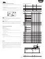
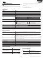
Proportional and integral control - PI
If the integration time ≠ 0, the P+I algorithm is implemented. The following
graph shows the case of OPENING when the proportional band for the
damper and the hot and cold water valves have the same value, with the
activation delta set to zero.
U
100%
VF
VC
S
OPENING IN HEATING:
• the actuators follow a ramp trend, without steps. When the damper
S
is completely open, the valve starts opening gradually, as the error
increases due to the contribution of the integration factor;
CLOSING IN HEATING:
• the valve starts closing when the room temperature exceeds point A.
P116
P110
P109
P113
P109
P114
P115
When the valve is completely closed, the damper starts closing, until
reaching the minimum position (20%).
TA (°C)
P114
BEHAVIOUR IN THE DEAD BAND:
• around the set point (±P109) the actuators stop at the position
P01
calculated when entering the dead band.
Fig. 4.k.a
Key:
P01
P109
P110
P113
P114
P115
P116
U
set point
dead band
heating valve on delta
cooling valve on delta
damper prop. band
cooling valve prop. band
heating valve prop. band
U
TA
outputs
room temperature
(control probe)
outside damper
cooling valve
heating valve
S
VF
VC
100%
S
VC
P119=20
Note that:
• the control signal is sent to the actuators outside of the dead band
• the valve has a proportional band for heating and another for cooling
• the actuators are activated in sequence: first the damper, then the
valve, which will begin opening outside of the damper proportional
band, as illustrated in the figure.
P114=P116
P109
TA (°C)
P109
A
P01
Fig. 4.k.c
Key:
P01
P109
P110
P113
P114
P116
In this case, the valve is activated when the damper is completely open,
with a control signal corresponding to the percentage of opening at that
point (>0%). As regards CLOSING, first the valve will close completely
and then the damper will start closing, at a temperature equal to the
complete closing temperature of the valve plus a ΔT equal to two times
the dead band:
set point
dead band
heating valve on delta
cooling valve on delta
damper prop. band
heating valve prop. band
U
TA
S
VC
outputs
room temperature
(control probe)
outside damper
heating valve
The behaviour for opening and closing in cooling is similar but opposite.
ΔT = 2*P109
U
Actuator movement control
100%
(parameter 99)
VC
S
A parameter is available that limits the movements of the valve so as to
reduce wear and adapt the P+I output to the effective resolution for the
position of the actuator. In fact, a minimum variation in the P+I output can
be established before the output effectively switches (parameter P99).
2xP109
P116
P110
P114
TA (°C)
Reduction in the effect of changing modes and/or
operating parameters (bumpless transfer)
P109
P01
(parameter 107)
Fig. 4.k.b
Key:
P01
P109
P110
P113
P114
P116
set point
dead band
heating valve on delta
cooling valve on delta
damper prop. band
heating valve prop. band
U
TA
S
VC
The “bumpless transfer” parameter, in response to changes in the P+I
algorithm control parameters during the normal operation of the unit,
dampens any swings or over-corrections of the system, especially when
the algorithm interacts with multiple devices or actuators.
outputs
room temperature
(control probe)
outside damper
heating valve
Modulating valve/damper management
The behaviour for closing in cooling is similar but opposite.
(parameters 97,102,103)
(*) Note that as there are a maximum of two modulating 0 to 10 Vdc outputs,
the heater can be controlled with the P+I algorithm only if the damper is on/
off. The activation delta and the proportional band are parameters P111 and
P117.
For modulating management of the actuators, parameters P15, P16, P17
must all be set >0.
For correct use of the 3-point actuators, the time taken for complete
opening or closing must be entered.
MasterAria +030220481 - rel. 1.0 - 12.11.2007
26
ENG
Par
97
Description
3-point valve actuator
travel time
102 Inactivity hysteresis
Def1 Def2 Def3 Min
120 120 120 1
Max
255
UOM
s
0
100
%
0
0
0
V
set point
ON
If output<P102,
output=0
If output >100%-P102,
output =100%
103 3-point damper actuator 150
travel time
OFF
150
150
0
255
TA (°C)
P06
s
Fig. 4.l.a
Tab. 4.h.8
Key:
V
TA
valve
room temperature (control probe)
Synchronisation
Par Description
06 Thermostat hysteresis
When the MasterAria is shutdown (switched from ON ->OFF), powered
up, or when total closing is requested (in this case, the minimum time
between two synchronisation cycles is 6 hours), a complete closing
cycle is performed to ensure correct alignment between the position
determined by the P+I algorithm and the real position, as there may in
fact be misalignments due to mechanical wear after a significant number
of operations. The synchronisation procedure is only performed on the
3 point valves, while for the valves with 0 to 10 V input, the function
is managed by the electronics on the actuator. The return to normal
operating conditions after a synchronisation cycle is managed according
to the normal dynamics of the P+I algorithm, given that the extent of the
error at the moment of synchronisation cannot be known.
Small deviations between the theoretical and the actual position are
automatically compensated for by the integration factor.
Def1 Def2 Def3 Min
5
5
5
0
TA
Set +P07
set point
t
TB
P14-P13
(cool enable)
t
ON
OFF
Antistick function
med
min
OFF
To prevent the valves from blocking (due to impurities or the entrainment
of solid residues in the water circuit), set movements of the valve are
performed periodically. These operations are only performed after a
certain period in which the valve is inactive (for example, when the set
point has been reached or when the device is off ). For the valves with 0 to
10 V input, this function is managed by the electronics on the actuator.
101
t
FAN
(parameters 100,101)
Description
Def1 Def2 Def3 Min
Maximum valve
4
4
4
0
stationary time (to
unlock)
(0=antistick function
disabled)
Forced movement for
20
20
20
0
antistick.
Considered as a % of the
maximum travel set
Max
255
UOM
hrs
100
%
UOM
°C/10
Below is an example of the activation sequence of the MasterAria loads;
the AHU is fitted with a hot/cold water valve and is operating in cooling
mode with the fan speed established by the autofan function (control
probe B1).
V
Par
100
Max
255
t
1
2
3
4
5
6
7
Fig. 4.l.b
Key:
TA
TB
V
FAN
1.
2.
3.
4.
5.
6.
7.
t
Tab. 4.h.9
room temperature (probe B1)
coil temperature (probe B2)
valve
fan
mode changed by user
extra flush cycle
select speed by autofan
activate ventilation by cool enable
change speed by autofan
deactivate valve & fan when set point reached
flush cycle
time
Cooling (management of the hot/cold water or cold
water valve only)
The activation of the hot/cold water or cold water valve only is decided
based on the set point (see the figure below), while the activation of the
fan depends on the cool enable function (at the speed selected by the
user or decided by the autofan function). When the room temperature
(i.e. the value measured by the control probe) reaches the set point, the
hot/cold water or cold water valve only is closed and the fan is stopped.
Heating (management of the hot/cold water valve or
hot water valve only)
The activation of the hot/cold water or hot water valve only is decided
based on the set point (see the figure below), while the activation of the
fan depends on the heat enable function (at the speed selected by the
user or decided by the autofan function).
When the room temperature (i.e. the value measured by the control
probe) reaches the set point, the hot/cold water or hot water valve only
is closed and the fan is stopped.
27
MasterAria +030220481 - rel. 1.0 - 12.11.2007
ENG
TA
set point
V
set point
ON
TB
OFF
TA (°C)
P06
t
P12+P13
P11+P13
P10+P13
t
V
Fig. 4.m.a
Key:
V
TA
ON
OFF
FAN
valve
room temperature (control probe)
Par Description
06 Thermostat hysteresis
t
med.
min.
OFF
Def1 Def2 Def3 Min
5
5
5
0
Max
255
t
UOM
°C/10
1
2
3
4
5
6
7
Fig. 4.m.d
A heater can be used (with dip 5= ON) to improve the heating function
and establish a different hysteresis depending on whether or not the
heat enable function is operating. To avoid possible overheating, the fan
is started at the same time as the heater, and remains on for a time equal
to P48 after the heater is shutdown. As extra protection, the heater is
deactivated if the coil temperature exceeds the value of parameter P47.
Key
TA
TB
V
FAN
1.
2.
3.
4.
5.
6.
7.
t
Case 1: heat enable active (no hot water)
V
R
P06
ON
OFF
P13
ON
OFF
TA (°C)
R
set point
TA (°C)
room temperature (probe B1)
coil temperature (heat enable)
valve
fan
mode changed by user
extra flush cycle
select speed by autofan
activate ventilation by heat enable & change speed
change speed by autofan
deactivate valve & fan when set point reached
flush cycle
time
Below is a further example of a unit fitted with hot/cold water valve or hot
water valve only and heater; it is operating in heating mode with the fan
speed established by autofan.
Fig. 4.m.b
Case 2: heat enable not active (hot water available)
( )
V
set point
Set-P46
P13
ON
OFF
TA
P46
R
P06
Set-P13
ON
OFF
P12+P13
(heat P11+P13
enable)
P10+P13
TA (°C)
Fig. 4.m.c
Key
R
TA
V
t
TB
set point TA (°C)
P46
t
V
ON
OFF
heater
room temperature (control probe)
valve
Par Description
13 - Hysteresis to enable fan
in heat/heat
AUTOMATIC, cool, cool
AUTOMATIC
- Heater hysteresis
(P39=6)
46 Heater band hysteresis
(see P39=6)
47 Max. coil temp. to
deactivate heater (see
P39=6)
48 Extra flush time with
heater
t
R
ON
OFF
Def1 Def2 Def3 Min
10
10
10
0
Max
255
t
FAN
U.M
°C/10
med.
min.
OFF
t
1
2
3
4
5
6
7
8
Fig. 4.m.e
30
30
30
0
255
°C/10
40
40
40
0
255
°C
20
20
20
0
255
s
Key
TA
TB
V
R
FAN
1.
2.
3.
4.
5.
6.
7.
8.
t
Tab. 4.h.10
Below is an example of the activation sequence of the MasterAria loads
in heating mode; the AHU is fitted with a hot/cold water valve or hot
water valve only and is operating in heating mode with the fan speed
established by autofan.
MasterAria +030220481 - rel. 1.0 - 12.11.2007
28
room temperature (probe B1)
coil temperature (heat enable)
valve
heater
fan
mode changed by user
extra flush cycle
activate valve & heater after extra flush
deactivate heater when thresh. exceeded w/ heat enable not active
speed by autofan
deactivate valve when set point reached
extra flush heater
flush cycle
time
ENG
Dehumidification
See the description of P+I control for the meaning of the parameters
Based on the set point, firstly the room temperature is controlled, cooling if
necessary, followed by the actual dehumidification cycle. In dehumidification
mode, the hot/cold water valve or cold water valve only is always open, fan
on/off cycles are run at minimum speed. The cool enable function is active
so as to ensure that the exchanger temperature is low enough for the water
vapour to condense. When the room temperature reaches the set point, the
dehumidification cycle stops, the fan is shut down and the hot/cold water
valve or cold water valve only is closed. If modulating actuators are used, the
valve is controlled by opening or closing completely.
Par
111
Description
Heater activation delta
Def1 Def2 Def3 Min
30
30
30
0
117
Heater proportional
band
0
0
0
0
Two options are available for the ON/OFF heater, each with its own
activation delta and hysteresis, depending on whether or not the P+I
algorithm is activated.
OFF
P49
P50
P49
P50
P49
P50
Fig. 4.n
Par Description
49 Fan on time in
dehumidification
50 Fan off time in
dehumidification
Def1 Def2 Def3 Min
3
3
3
0
Max
255
UOM
min
15
255
min
15
15
0
Important:
During the antifreeze alarm, only for AHUs with recirculation, the
heater is on until the temperature returns to normal values. This applies
to the modulating 0 to 10 Vdc (P39=17) or ON/OFF heater (P39=18), and
not the ON/OFF heater option P39=6.
Case 1 (P+I algorithm activated): P39=18
Tab. 4.h.11
R
ON
P112
Key:
R heater
TA room
temperature
(control probe)
Ventilation
OFF
In this mode, the hot or cold water valve is always closed and the fan
operates at the speed selected by the user (in autofan, it works at medium
speed). The fan is only started if the room temperature is within the range
of temperatures specified by parameters P30 and P31, to avoid undesired
flows of hot or cold air.
ON
P06
OFF
set point
Fig. 4.p.a
P06
P31
TA (°C)
Fig. 4.o
Prog Description
06
Thermostat hysteresis
30
Fan set point (Manual &
AUTO)
31
Fan differential (Manual
& AUTO)
Def1 Def2 Def3 Min
5
5
5
0
15
15
15
0
Max
255
255
UOM
°C/10
°C
20
255
°C
20
20
0
TA (°C)
P111
P30
Par Description
39 Config. output NO4
18 Output (triac or
relay) for man. of
ON/OFF heaters
(with hysteresis) on
P+I. Set parameters
P111, P112.
Def1 Def2 Def3 Min
13
13
9
0
Max
24
UOM
---
40
Configuration of output
NO5 (see P39)
41 Configuration of output
NO6 (see P39)
42 Configuration of output
NO7 (see P39)
111 Heater activation delta
14
21
10
0
24
---
23
18
19
0
24
---
0
24
20
0
24
---
30
30
30
0
255
112 Heater hysteresis
(p39=18)
5
5
5
0
Tab. 4.h.12
Heater
A heater can be managed for the pre-heating, heating and post-heating
functions required by the application. If parameter 118≠2 (continuous
fan operation), the fan is started at the same time as the heater, and
remains on for a time equal to P48 after the heater shuts down. As further
protection, the heater is deactivated if the coil temperature exceeds the
value of parameter P47.
48
UOM
°C
/10
255 °C
/10
Tab. 4.h.14
ON/OFF heater
ON
Par
47
Max
255
Description
Max. coil temp. to
deactivate heater (see
P39=6)
Extra flush time with
heater
Def1 Def2 Def3 Min
40
40
40
0
Max
255
Case 2 (P+I algorithm NOT activated): P39 =6
R
ON
UOM
°C
P13
OFF
TA (°C)
P46
set point
20
20
20
0
255
°C
/10
255 °C
/10
Tab. 4.h.15
Key:
R heater
TA room
temperature
(control probe)
Fig. 4.p.b
s
Tab. 4.h.13
0 to 10 Vdc heater
29
MasterAria +030220481 - rel. 1.0 - 12.11.2007
ENG
Par
39
Description
Config. output NO4
40
41
42
13
46
Configuration of output NO5 (see P39)
Configuration of output NO6 (see P39)
Configuration of output NO7 (see P39)
Heater hysteresis (P39=6)
Heater band hysteresis (see P39=6)
Def1 Def2 Def3 Min
13
13
9
0
Max
24
14
23
0
10
30
24
24
24
255
255
UOM
---
6 ON/OFF heater (normally open) (set parameters P46 & P13);
AUTOMATIC operation:
Heating/Cooling
10
19
20
10
30
0
0
0
0
0
------°C/10
°C/10
Tab. 4.h.16
The fan and the cold/hot water valve are managed in the same way as
in heating/cooling mode (the flush function is not active). The heater is
managed in the same way as in heating mode. In AUTOMATIC OFF, the
cold/hot water valve is closed and the flush function is active. If when
entering AUTOMATIC mode the room temperature falls into the hysteresis
zone, priority is given to heating mode. When cooling mode is activated,
the control set point is the set point + P02, while in heating mode the
control set point is the set point - P03.
In AUTOMATIC mode, MasterAria measures the room temperature and
decides which mode to activate (cooling or heating) based on the set
point. The criterion is illustrated in the graph.
U
H
21
18
24
10
30
C
P05
P03
P109 P109
1
P02
2
P04
P+I ALGORITHM: The mode, heating or cooling, is determined according
to the graph shown on the side, then the P+I algorithm enters into play,
managing the outputs. The mode is changed only after all the actuators
have been deactivated, as a consequence the internal parameters are
reset each time. It should be noted that P02, P03, P04 and P05 involve
a further activation hysteresis (in additional to the P+I dead band)
and therefore the parameters must be set appropriately. The values of
parameters P04 and P05 should be set lower than the dead band.
TA (°C)
3
Fig. 4.q
Key
H
C
P109
U
heating
cooling
dead band
op. mode
Prog
02
03
04
05
Description
AUTOMATIC mode: Set point differential in cooling
AUTOMATIC mode: Set point differential in heating
AUTOMATIC mode: Cooling hysteresis
AUTOMATIC mode: Heating hysteresis
1.
2.
3.
TA
cooling set point
control set point
cooling set point
room temperature (cont. probe)
Def1
0
0
0
0
Def2
0
0
0
0
Def3
0
0
0
0
Min
0
0
0
0
Max UOM
255 °C/10
255 °C/10
255 °C/10
255 °C/10
Tab. 4.h.17
The set point can be adjusted in relation to the outside temperature, so as
to avoid significant differences when entering/leaving the environment
or to compensate for the thermal dispersion of the environment itself.
The parameters are differentiated between cooling and heating, and
the coefficient applied may be positive or negative, depending on the
desired effect.
Case 1: Cooling
If Text > Set + P23
If Text < Set + P23
Case 1: Heating
If Text > Set - P25
If Text < Set - P25
Compensation using the outside temperature probe
Set_comp = Set+{[Text-(Set+P23)]*P24}
Set_comp = Set
Set_comp = Set+{[Text-(Set-P25)]*P26}
Set_comp = Set
Set_comp
Set_comp
P24=2
P26=-2
P24=+0,5
P26=-0,5
Set =3 °C
Set =2 °C
Set
Set
Set =2 °C
P24=-0,5
Set =3 °C
P26=+0,5
P26=+2
P24=-2
Set + P23
Text
Set - P25
Fig. 4.r.a
Key (Fig. 4.r.a & Fig. 4.r.b)
Set
Set point
Set_comp
Set point with compensation
P23
Set point delta for compensation in cooling
Fig. 4.r.b
P24
P25
P26
Text
The set point with compensation cannot in any case exceed values greater than or
less than 3 °C (cooling) and 2 °C (heating) from the set point (saturation).
MasterAria +030220481 - rel. 1.0 - 12.11.2007
30
Factor for compensation in cooling
Delta set point for compensation in heating
Factor for compensation in heating
Outside temperature
Text
ENG
Par
22
Description
Select optional compensation probe
0
Compensation disabled
1
Compensation enabled on B1 = outside probe
2
Compensation enabled on B3 = outside probe
Def1 Def2 Def3 Min
0
0
0
0
Max
2
23
24
25
26
Set point delta for compensation in cooling (0 = Compensation disabled)
Factor for compensation in cooling (0 = Compensation disabled)
Set point delta for compensation in heating (0 = Compensation disabled)
Factor for compensation in heating (0 = Compensation disabled)
0
0
0
0
127
20
127
20
0
0
0
0
0
0
0
0
-99
-20
-99
-20
UOM
---
°C/10
--°C/10
--Tab. 4.h.18
4.3 Outlet limits
only)
Outlet limits are particularly useful in applications where the AHU is
controlled based on the return (intake) or room temperature, and have
the purpose of preventing air that is too cold or too hot from being
introduced into the environment. To do this, these limits act directly on
the heating and cooling devices, bypassing the other algorithms.
During the winter period, there are two cases in which the minimum
outlet limit may be enabled:
• when the room temperature reaches the set point and the heating coil
closes completely, if the outside air is too cold a situation of discomfort
will be created inside the environment near the air distributors;
• when freecooling is active in crowded environments such as discos,
pubs etc., if the outside air is too cold the same problem as described
above occurs.
Minimum outlet limit on the cold water valve
TM
In these cases, to speed up the correction, the heating coil needs to be
activated by the outlet probe.
Depending on the heating devices used, the following actions are
implemented:
1. Heating valve: when the outlet temperature falls below the minimum
outlet temperature (TMm), MasterAria starts opening the heating
valve until opening completely at the value of (TMm-Diff ).
2. Modulating heater only: same operation as for the modulating
valve.
3. ON/OFF heater only: as shown in the graph, if the only heating device
is the ON/OFF heater, then it switches on at (TMm - Diff ).
TMm
TMm - Diff
t
100%
VF
0%
t
ON
S
TM
OFF
TMm
t
90 s
Fig. 4.s
Key
t
time
VF
cooling valve
S
damper
TM
TMm
Diff
TMm - Diff
outlet temperature
min outlet temp. (P106)
outlet limit diff. (P126)
t
100%
VC/RM
0%
1. Cold water valve: when the outlet temperature falls below the
t
minimum outlet temperature (TMm), MasterAria starts closing the
cold water valve until closing completely at the value of (TMm-Diff ).
2. Outside damper: if a modulating damper is used and freecooling/
heating management is available, the outlet limit acts on the damper
only if the action on the cooling coil is not sufficient. If 90 seconds after
closing the valve the outlet temperature continues to remain below
the minimum outlet temperature minus a differential, the damper is
moved to the minimum position (P119). For ON/OFF dampers, the
damper is closed.
ON
R
OFF
t
Fig. 4.t
Key
t
time
VC/RM mod. heating valve/
heater
R
ON/OFF heater
While the outlet limit conditions remain, the integral action of the control
algorithm is suspended.
Par Description
106 Minimum cooling valve/
heating valve-heater
outlet temperature
119 Minimum outside
damper position
126 Outlet limit differential
Def1 Def2 Def3 Min
127 18
18
-28
Max
127
UOM
°C
0
20
20
0
100
%
20
20
20
10
255
°C/10
Tab. 4.i
Par
106
126
TM
TMm
outlet temperature
min outlet temp. (P106)
Diff
outlet limit diff. (P126)
Description
Def1 Def2 Def3 Min Max
Minimum cooling valve/ 127(*) 18
18
-28 127
heating valve-heater
outlet temperature
Outlet limit differential
20
20
20
10
255
UOM
°C
°C/10
Tab. 4.j
(*) 127 = function disabled
Maximum outlet limit
Minimum outlet limit on the hot water valve (heating
This limit is implemented when the AHU is working in heating mode and
due to sudden variations in the outside environmental conditions or faults
31
MasterAria +030220481 - rel. 1.0 - 12.11.2007
ENG
on the unit, air that is too hot starts being blown into the environment. In
this case, MasterAria starts reducing the action of the heating coil.
Freecooling/freeheating dampers
MasterAria can manage the outside air damper, the recirculation damper
and the heat recovery unit bypass damper. The first two dampers have
complementary behaviour and can be managed by the same output
with a parallel connection. The actuators have a selector for reversing
the direction of rotation. For convenience, reference will only be made
to the outside air damper. The type of management can be on/off or
proportional.
Depending on the heating devices used, the following actions are
implemented:
1. Heating valve: when the outlet temperature exceeds the maximum
outlet temperature (TMM), MasterAria starts closing the heating valve
until closing completely at the value of (TMM+Diff ).
2. Modulating electric heater: same operation as for the heating valve.
3. Heating valve + ON/OFF heater: first the heater is switched off and
then the valve closes.
4. Outside damper: if a modulating damper is used and freecooling/
heating management is available, the outlet limit acts on the damper
only if the action on the heating coil is not sufficient. If 90 seconds after
closing the valve the outlet temperature continues to remain above
the maximum outlet temperature plus a differential, the damper is
moved to the minimum position (P119). For ON/OFF dampers, the
damper is closed.
ON/OFF damper
The management of these types of dampers is quite simple.
The behaviour of the damper is in fact very similar to the AHU itself, as can
be seen from the graph. Note the extra flush cycle if the electric heater
is fitted.
ON
CTA
OFF
TM
TMM + Diff
t
ON
AL
TMM + Diff
2
OFF
TMM
t
ON
S
t
OFF
100%
t
P48
VC/RM
Fig. 4.v
0%
Key:
AHU
AL
S
t
t
ON
R
OFF
t
100%
V
0%
t
Par Description
39 Config. output NO4
23 ON/OFF outside
damper
Def1 Def2 Def3 Min
13
13
9
0
Max
24
UOM
---
40
14
21
10
0
24
---
23
18
19
0
24
---
20
20
20
0
255
s
Configuration of output
NO5 (see P39)
Configuration of output
NO6 (see P39)
Extra flush time
with heater
41
ON
48
S
OFF
air handling unit
antifreeze alarm
damper
time
t
90 s
Tab. 4.l
Fig. 4.u
Key
t
V
R
S
time
heating valve
ON/OFF heater
damper
Prog Description
125 Maximum outlet
temperature
126 Outlet limit differential
TM
TMM
Diff
VC/RM
Proportional 0 to 10 Vdc damper
outlet temperature
max. outlet temp.
outlet limit diff.
modulating heating valve/
heater
Def1 Def2 Def3 Min Max
127 (*) 28
28
-28 127
UOM
°C
20
°C/10
Tab. 4.k
MasterAria manages the proportional damper using the P+I control
algorithm, described in the corresponding paragraph.
U
100%
20
20
10
255
H
(*) 127 = function disabled
C
P119
P114
P109
P109
P114
TA (°C)
Fig. 4.w
Key:
MasterAria +030220481 - rel. 1.0 - 12.11.2007
32
P114 damper prop. band
ENG
U
P+I output
P109 dead band
P119 minimum damper position
H
C
TA
heating
cooling
room temperature
(control probe)
The proportional damper features a minimum position, set by the user
(P119), below which the damper cannot be closed, except in the event
of alarms.
It is opened beyond the minimum position if the freecooling and
freeheating conditions require.
Prog. Description
15
Function of probe B1
6
Outside probe
Def1 Def2 Def3 Min
7
7
7
0
Max
7
UOM
---
16
4
2
4
7
---
6
6
6
0
7
---
13
13
9
0
24
---
14
21
10
0
24
---
23
18
19
0
24
---
0
24
20
0
24
---
0
20
20
0
255
°C/10
0
20
20
0
255
°C/10
Funct. probe B2 (par.
table)
Funct. probe B3 (par.
table)
Config. output NO4
17
39
19
20
Freecooling and freeheating
21
The freecooling/freeheating function is used to exploit the outside
temperature conditions, when these are favourable, adjusting the
opening of the outside damper.
To be able to use these functions:
• connect and enable the outside and room temperature probes;
• set the freecooling differential;
• set the freeheating differential.
40
41
42
104
In the summer period, the conditions to allow freecooling are:
T Room - T OUTSIDE > Freecooling activation delta (P104)
105
S
Open 3-point
outside damper
Close 3-point
outside damper
0 to 10 Vdc
outside damper
Configuration of output
NO5 (see P39)
Configuration of output
NO6 (see P39)
Configuration of output
NO7 (see P39)
Freecooling activation
delta
Freeheating activation
delta
Tab. 4.m
100%
Heat recovery unit
The MasterAria can manage cross-flow heat recovery units, with the
corresponding bypass damper. The heat recovery unit is an excellent
device for ensuring energy saving, as it exploits the air discharged from
the environment to heat (in heating mode) or cool (in cooling mode) the
outside air taken in by the AHU.
0%
1
P109
TA (°C)
P114
Fig. 4.x.a
Key:
S
outside damper
TA
room temperature (control probe)
1.
set point
If the condition is satisfied, then the damper starts opening according to
the normal control signal, based on the control probe reading.
In the winter period, the conditions to allow freeheating are:
Aria
esterna
Aria
ambiente
Aria di
espulsione
Aria di
mandata
T OUTSIDE - T Room > Freeheating activation delta (P105)
Fig. 4.y.a
S
The role of the bypass damper is to bypass the heat recovery unit
when the outside and room temperatures would not allow good heat
recovery.
Normally, the heat recovery unit is bypassed when the outside conditions
are favourable, that is, when freecooling or freeheating are active.
MasterAria can only manage on/off actuators in this case ON/OFF.
100%
0%
P114
P109
1
TA (°C)
Fig. 4.x.b
Operation:
Key:
S
outside damper
TA
room temperature (control probe)
1.
set point
Cooling
If cooling is required, the bypass damper only closes if: (T OUTSIDE - T ROOM)
> P127
If the condition is satisfied, then the damper starts opening according to
the normal control signal, based on the control probe reading.
Heating
If heating is required, the bypass damper only closes if: (T ROOM - T OUTSIDE)
> P127
Disabling:
To disable the freecooling and freeheating functions, set the
respective differentials to zero (parameters P104 and P105).
Both conditions are maintained for a minimum of 5 minutes, to avoid
situations of instability when the temperature fluctuates around the set
point.
Antifreeze
If the antifreeze conditions are true, MasterAria opens the bypass
damper.
33
MasterAria +030220481 - rel. 1.0 - 12.11.2007
ENG
1
3
Key
1.
2.
3.
2
4
P127
t
AL
T ROOM - T OUTSIDE
time
antifreeze alarm
recovery bypass damper
Prog Description
15
Function of probe B1
6 Outside probe
Def1 Def2 Def3 Min
7
7
7
0
Max
7
UOM
---
16
4
2
4
7
---
6
6
6
0
7
---
13
13
9
0
24
---
14
21
10
0
24
---
23
18
19
0
24
---
0
24
20
0
24
---
20
20
20
0
255
°C/10
ON
17
OFF
t
4.
t
AL
S
cooling
heating
T OUTSIDE - T ROOM
39
Function of probe B2
(see par. table)
Function of probe B3
(see par. table)
Config. output NO4
24 ON/OFF recovery
bypass damper
S
100%
40
0%
41
t
Fig. 4.y.b
42
127
Configuration of output
NO5 (see P39)
Configuration of output
NO6 (see P39)
Configuration of output
NO7 (see P39)
Close bypass damper
set point
Tab. 4.n
4.3 Notes on settings via serial connection
All the MasterAria parameters can be viewed and those without write
protection modified via serial connection (PlantVisor and Modbus®).
Below is a short description of the most significant variables (for the
settings, see the summary table of parameters).
Variable
Control probe
Meaning
This variable contains the value of the probe used to control the MasterAria (B1 or BT).
The value considers any offsets, hysteresis, control algorithms etc.
Set point setting
This variable is used to read and where necessary overwrite the value of the set point
configured on the panel. This is especially useful if the MasterAria has the comfort
function active (e.g. centralised systems such as hotels, offices etc.).
Control set point
This variable is used to read the value of the control set point used by MasterAria.
The value considers the hysteresis, compensation factors, offsets (e.g.: sleep function),
algorithms etc.
Digital inputs & heat/cool Heating/cooling signal: the bits are set when the unit is ON and the set point has not
request
been reached. Especially useful for energy saving functions.
Lock keypad from panel This variable is used to disable the buttons on the terminal so as to prevent accidental
settings. Useful for centralised systems (hotels, offices etc.).
Type
A
SV ind Modbus® ind R/W
74
74
R
I
83
211
R/W
A
76
76
R
I
81
209
R
I
78
206
R/W do not
modify
Tab. 4.o
Notes
Load defaults or reset from
key
Priority
1
4.4 Alarms
Below is the table of alarms.
Alarm
Eeprom fault on power up
Slave offline in CAN network
Room probe fault
Probe B2 or B3 fault
Window alarm A05
Circulating pump stopped
Local stop
Antifreeze alarm
Dirty filter alarm
Display Effect
A01
Stop fan (with extra flush for heater).
Close hot/cold water valves. Switch off heater.
A02
A03
A04
A05
A06
A07
A08
AHU 100% outside air:
AHU with recirculation:
A09
•
Stop fan (after optional
extra flush with heater)
•
•
•
•
•
•
Close outside damper
Open heating valve
Open cooling valve when
no heating valve
•
•
2
3
4
5
6
7
8
Fan operating
Close outside damper
Activate heating device (heater or
valve)
Open cooling valve, with no heating
valve or heater
Open bypass damper
Signal only on terminal
9
Tab. 4.p
MasterAria +030220481 - rel. 1.0 - 12.11.2007
34
ENG
should be connected directly to the digital input configured as the local
stop. In this case, MasterAria deactivates the fan output and closes the
valve.
Fan circuit breaker
To ensure both software and electromechanical protection, as shutting
down the fan implies stopping the entire unit, the fan circuit breaker
Prog Description
43
Configuration of digital input 3
5 local stop (normally open)
10 local stop (normally closed)
Def1 Def2 Def3 Min
10
10
10
0
Max
14
UOM
---
44
45
12
14
14
14
----Tab. 4.q
Configuration of digital input 4 (see P43)
Configuration of digital input 5 (see P43)
12
14
12
14
0
0
The alarm is indicated on the display by code A07.
Dirty filter alarm
By nature, the filters on an AHU will become clogged with all the
impurities present in the air.
When the filters are excessively clogged, not only do they no longer carry
out their filtering function, but they also represent a significant pressure
drop for the AHU. To warn the user of this risk, MasterAria manages the
dirty filter alarm.
The signal that generates the alarm is sent by the digital pressure switch
that measures the pressure difference upstream and downstream of the
filter. If the pressure difference exceeds the threshold set by a trimmer in
the pressure switch, the contact opens, generating the alarm. The alarm
is signal-only, and does not affect the normal operation of the AHU in
any way.
.
Prog Description
43
Configuration of digital input 3
13 dirty filter alarm from differential pressure switch (normally open)
14 dirty filter alarm from differential pressure switch (normally closed)
Def1 Def2 Def3 Min
10
10
10
0
Max
14
UOM
---
44
45
12
14
14
14
----Tab. 4.r
Configuration of digital input 4 (see P43)
Configuration of digital input 5 (see P43)
12
14
12
14
0
0
• the fan is kept on;
• operates the heating device at 100%, with priority given to the heater
The alarm is indicated on the display by code A09.
Antifreeze alarm
if fitted, otherwise the heating valve;
The condition that causes the antifreeze alarm is very critical for an
AHU, as it may cause irreparable damage to the water coils and the heat
recovery unit. The antifreeze alarm can be activated by probe (P121,
P122=activation threshold, deactivation threshold) or by thermostat.
MasterAria, when managing an antifreeze situation, distinguishes the
type of AHU: 100% outside air or recirculation (P124).
• if there are no heating devices, the cold water valve is fully opened to
see whether this can prevent the coil from freezing;
• the display shows the alarm A08;;
AHU with heat recovery unit
The ON/OFF damper on the heat recovery unit is opened during the
antifreeze alarm. In systems with P91=45, the behaviour of the fan, heater
and valve is the same as for the AHU with 100% outside air (P124 = 0).
Important: parameter P124 must be set correctly!
AHU with 100% outside air
This unit only has the outside damper and not the recirculation damper.
This means that the AHU only works with the air only coming in from the
outside.
In the event of antifreeze alarms, MasterAria responds as follows:
• closes the outside air damper;
• stops the fan;
• operates the heating device at 100%, unless the electric heaters are
being used, which are kept off or switched off if on;
• if there are no heating devices or there are only electric heaters, the
cold water valve is fully opened to see whether this can prevent the
coil from freezing;
• the display shows the alarm A08.
Return to normal operation
In the cases described above, the AHU automatically returns to normal
operation when the temperature measured by the probe returns to
normal values or when the thermostat contact opens.
There is in any case a programmable delay (P123 ) that controls the return
to normal operation.
AHU with recirculation
This unit has both the outside damper and the recirculation damper.
This means that the air coming in from the outside and the air from the
environment are mixed inside the AHU.
In the event of antifreeze alarms, MasterAria responds as follows:
• closes the outside air damper;
• completely opens the recirculation damper;
35
MasterAria +030220481 - rel. 1.0 - 12.11.2007
ENG
Prog Description
15
Function of probe B1
3
Cooling coil probe
4
Heating coil probe
Def1 Def2 Def3 Min
7
7
7
0
Max
7
UOM
---
16
17
43
4
6
10
2
6
10
6
10
4
0
0
7
7
14
-------
12
14
0
12
14
2
12
14
2
0
0
0
14
14
2
-------
2
7
2
0
2
7
2
1
2
7
2
1
-28
-28
1
0
50
50
255
1
°C
°C
min
---
Function of probe B2 (see P15)
Function of probe B3 (see P15)
Configuration of digital input 3
11
12
44
45
120
Configuration of digital input 4 (see P43)
Configuration of digital input 5 (see P43)
Enable antifreeze
0
1
2
121
122
123
124
enable antifreeze by time (normally open)
enable antifreeze by time (normally closed)
Disabled
Enable by probe
Enable by digital input
Antifreeze activation threshold
Antifreeze deactivation threshold
Antifreeze time
Unit model
0
1
100% outside air
With recirculation
Tab. 4.s
4.5 Table of parameters
P
00
Parameter
Software version
Def.1 Def.2 Def.3 Min
---------
Max
---
UOM SV type SV #
--I
1
Modbus® access
129
U
01
02
AUTOMATIC mode set point
AUTOMATIC mode:
Set point differential in cooling
AUTOMATIC mode:
Set point differential in heating
AUTOMATIC mode: Cooling hysteresis
AUTOMATIC mode: Heating hysteresis
Thermostat hysteresis
Delta for medium speed in Autofan
Delta for maximum speed in Autofan
Fan speed hysteresis in Autofan
Temperature to enable minimum fan speed in heating/
AUTOMATIC heating
Temperature to enable medium fan speed in heating/
AUTOMATIC heating
Temperature to enable maximum fan speed in heating/
AUTOMATIC heating
- Hysteresis to enable fan in heating/AUTOMATIC heating,
cooling, AUTOMATIC cooling
- Heater hysteresis with heat enable active (P39=6)
Temperature to enable fan in cooling/AUTOMATIC cooling
& dehumidification
Function of probe B1
22
0
22
0
22
0
0
0
255
255
°C
A
°C/10 A
1
2
1
2
U
U
0
0
0
0
255
°C/10 A
3
3
U
0
0
5
7
7
5
29
0
0
5
7
7
5
29
0
0
5
7
7
5
29
0
0
0
0
0
0
0
255
255
255
255
255
255
255
°C/10
°C/10
°C/10
°C/10
°C/10
°C/10
°C
A
A
A
A
A
A
A
4
5
6
7
8
9
10
4
5
6
7
8
9
10
U
U
U
U
U
U
U
33
33
33
0
255
°C
A
11
11
U
37
37
37
0
255
°C
A
12
12
U
10
10
10
0
255
°C/10 A
13
13
U
21
21
21
0
255
°C
A
14
14
U
7
7
7
0
7
---
I
105
233
U
03
04
05
06
07
08
09
10
11
12
13
14
15
0
1
2
3
4
5
6
7
With dipswitch6 = ON, control probe is probe on
“acqua” terminal
Probe disabled
Heating/cooling coil probe
Cooling coil probe
Heating coil probe
With dipswitch6 = OFF, control probe is probe B1
(intake/return)
Outside probe
Outlet probe
MasterAria +030220481 - rel. 1.0 - 12.11.2007
36
notes
E.g.10 =
v1.0
ENG
P
16
17
18
19
20
21
22
Parameter
Function of probe B2 (see P15)
Function of probe B3 (see P15)
Increase cooling/dehumidification set point in sleep
Decrease heating set point in sleep
ADC limitation coefficient
ADC average coefficient
Select optional compensation probe
0
1
2
23
24
25
26
28
Max
7
7
255
255
15
15
2
UOM
----°C/10
°C/10
-------
0
0
0
-99
127
0
0
0
-20
0
0
0
0
0
0
SV type
I
I
A
A
I
I
I
SV #
106
107
18
19
2
3
4
Modbus®
234
235
18
19
130
131
132
access
U
U
U
U
U
U
U
°C/10 A
20
20
U
20
---
A
21
21
U
-99
127
°C/10 A
22
22
U
0
-20
20
---
A
23
23
U
0
0
0
3
---
I
6
134
U
15
20
2
15
20
2
15
20
2
0
0
0
255
255
255
°C
°C
min
A
A
I
24
25
8
24
25
136
U
U
U
90
90
90
0
255
s
I
9
137
U
0
0
0
0
3
---
I
10
138
U
30
0
30
0
30
0
0
0
255
1
s
---
I
I
11
12
139
140
U
U
0
0
0
0
5
---
I
13
141
U
0
0
0
0
255
---
I
14
142
U
notes
Compensation disabled
Factor for compensation in heating
0
Min
0
0
0
0
0
0
0
Compensation disabled
Set point delta for compensation in heating
0
Def.3
2
6
10
10
6
6
0
Compensation disabled
Factor for compensation in cooling
0
Def.2
2
6
10
10
6
6
0
Compensation disabled
Compensation enabled on B1=outside probe
Compensation enabled on B3=outside probe
Set point delta for compensation in cooling
0
Def.1
4
6
10
10
6
6
0
Compensation disabled
Visibility of output values to supervisor
0 Disabled
1 Enabled
2,3 DO NOT SELECT
30
31
32
Fan set point (Manual & AUTO)
Fan differential (Manual & AUTO)
Flush off
0 Disabled
>0 Fan off time
33
Flush on
0 Disabled
>0 Fan on time
34
Flush mode
0
1
2
3
35
36
Flush time when changing mode
Select AUTOMATIC with Set point or Comfort
0
1
37
Comfort function disabled
(set point can be changed from “acqua” terminal)
Enable Comfort
(only ±3 °C change in set point from P01)
Display (“acqua” terminal)
0
1
2
3
4
5
38
Function disabled
Flush function active in cooling, dehumidification &
AUTOMATIC
Flush function active in heating & AUTOMATIC OFF
Flush function active in heating, cooling,
dehumidification & AUTOMATIC OFF
Display set point
Display control probe (BT or B1)
Display probe B2
Display probe B3
Display position of modulating valve
Display position of modulating damper
Disable operating mode
1
2
4
8
16
32
64
128
AUTOMATIC
cooling
dehumidification
ventilation
heating
autofan
sleep
ON/OFF timer & display clock
The setting is achieved by adding the values shown
below, each of which corresponds to the disabling of the
corresponding function.
EXAMPLE:
Activation of AUTOMATIC mode only: 2+4+8+16 = 30
37
MasterAria +030220481 - rel. 1.0 - 12.11.2007
ENG
P
39
Parameter
Configuration of output NO4
0
1
2
3
4
5
6
7
8
9
10
11
12
13
14
15
16
17
18
19
20
21
22
23
24
40
41
42
43
2
3
4
5
6
7
8
9
10
11
12
13
14
44
45
46
47
Max
24
UOM SV type SV #
--I
15
Modbus® access
143
U
14
23
0
10
21
18
24
10
10
19
20
10
0
0
0
0
24
24
24
14
---------
I
I
I
I
16
17
18
19
144
145
146
147
U
U
U
U
12
14
30
40
12
14
30
40
12
14
30
40
0
0
0
0
14
14
255
255
----°C/10
°C
I
I
A
A
20
21
26
27
148
149
26
27
U
U
U
U
Output disabled
ON/OFF cold water valve (norm. open)
ON/OFF hot water valve (norm. open)
Chiller activation signal, cold water request (norm.
open). Contact closed with cold/hot water valve
or cold water valve only active (open with valve
deactivated)
Boiler, heat pump activation signal, hot water
request (normally open). Contact closed with cold/
hot water valve or hot water valve only active (open
with valve deactivated)
ON/OFF hot/cold water valve (normally open).
Activated with cooling/heating request from
controller. Off when are both deactivated
ON/OFF heater(normally open) (set parameters P46
& P13)
Alarm (normally open)
DO NOT SELECT
3-point valve + (clockwise) for cold water (hot/cold
water if dip4=OFF)*
3-point valve - (anticlockwise) for cold water (hot/
cold water if dip4=OFF)*
3-point valve + (clockwise) for hot water
(deactivated if dip4=OFF) *
3-point valve - (anticlockwise) for hot water
(deactivated if dip4=OFF) *
Valve with 0 to 10 Vdc input for cold water (hot/cold
water if dip4=OFF) *
Valve with 0 to 10 Vdc input for hot water
(deactivated if dip4 =OFF) *
DO NOT SELECT
DO NOT SELECT
0 to 10 Vdc output for modulating heater control (by
external module). Set parameters P111, P117.*
Output (triac or relay) for man. of ON/OFF heaters
(with hysteresis) on P+I. Set parameters P111, P112.*
Open 3-point outside damper*
Close 3-point outside damper*
0 to 10 Vdc outside damper
DO NOT SELECT
ON/OFF outside damper
ON/OFF recovery bypass damper
(*) The P+I parameters need to be set
Configuration of output NO5 (see P39)
Configuration of output NO6 (see P39)
Configuration of output NO7 (see P39)
Configuration of digital input 3
0
1
Def.1 Def.2 Def.3 Min
13
13
9
0
input disabled
economy (norm. open) varies the set point
(cooling= increase, heating= decrease)
window alarm (norm. open) stops fan and closes
the valve
DO NOT SELECT
DO NOT SELECT
local stop (generic alarm norm. open) stops fan and
closes the valve
economy (norm.closed)
window alarm (norm. closed)
DO NOT SELECT
DO NOT SELECT
local stop (generic alarm normally closed). Stops the
fan and closes the valve
enable antifreeze by time (normally open)
enable antifreeze by time (normally closed)
dirty filter alarm from differential pressure switch
(normally open)
dirty filter alarm from differential pressure switch
(normally closed)
Configuration of digital input 4 (see P43)
Configuration of digital input 5 (see P43)
Heater band hysteresis (see P39=6)
Max. coil temp. to deactivate heater (see P39=6)
MasterAria +030220481 - rel. 1.0 - 12.11.2007
38
notes
ENG
P
48
49
50
51
52
53
54
55
Parameter
Extra flush time with heater
Fan on time in dehumidification
Fan off time in dehumidification
Hot/cold valve ON time during cycles
Max hot/cold valve OFF time during cycles
Min hot/cold valve OFF time during cycles
Serial communication mode (0=Carel; 1=Modbus)
Enable cool & heat symbols in AUTOMATIC
0
1
56
57
58
59
60
61
62
63
64
65
69
91
Manufacturer password
Note: enter manufacturer password to enable type F
parameters (=Factory)
95 SET TO 1: DO NOT MODIFY
97 3-point valve actuator travel time
99 Minimum P+I movement
Minimum variation in P+I output to move valve (for 0
to 10 V and 3 point valves) and increase heater output.
Expressed as a % of the total P+I output.
100 Maximum valve stationary time (to unlock)
1
2
3
108
109
110
111
112
113
114
115
116
117
Max
255
255
255
255
255
255
1
1
UOM
s
min
min
min
min
min
-----
SV type
I
I
I
I
I
I
I
I
SV #
22
23
24
25
26
27
28
29
Modbus®
150
151
152
153
154
155
156
157
access
U
U
U
U
U
U
F
U
1
1
1
0
1
---
I
30
158
U
0
0
0
0
-30
0
0
0
0
1
0
0
0
0
-30
0
0
0
0
1
0
0
0
0
-30
0
0
0
0
1
0
-99
-99
-99
-99
-99
-99
-99
-99
0
1
127
127
127
127
127
127
127
127
207
--°C/10
°C/10
°C/10
°C/10
°C/10
°C/10
°C/10
°C/10
---
I
A
A
A
A
A
A
A
A
I
31
28
29
30
31
32
33
34
35
35
159
28
29
30
31
32
33
34
35
163
U
U
U
U
U
U
U
U
U
F
0
0
0
0
255
---
I
57
185
F
0
0
0
0
255
---
I
58
186
F
1
120
5
1
120
5
1
120
5
0
1
0
1
255
100
--s
%
I
I
I
61
63
65
189
191
193
U
U
U
4
4
4
0
255
hrs
I
66
194
U
20
20
20
0
100
%
I
67
195
U
0
0
0
0
100
%
I
68
196
U
150
0
0
127
150
20
20
18
150
20
20
18
0
0
0
-28
255
255
255
127
s
°C /10
°C /10
°C
I
A
A
A
69
36
37
38
197
36
37
38
U
U
U
U
1
1
1
0
3
---
I
104
232
U
0
2
0
30
5
0
0
30
30
0
6
2
0
30
5
0
30
30
30
0
6
2
0
30
5
0
30
30
30
0
0
0
0
0
0
0
0
0
0
0
255
255
255
255
255
255
255
255
255
255
s*10
°C /10
°C /10
°C /10
°C /10
°C /10
°C /10
°C /10
°C /10
°C /10
I
A
A
A
A
A
A
A
A
A
99
43
44
45
46
47
39
40
41
42
227
43
44
45
46
47
39
40
41
42
U
U
U
U
U
U
U
U
U
U
notes
antistick function disabled
101 Forced movement for antistick.
Considered as a % of the maximum travel set
102 Inactivity hysteresis
If output <P102, output =0
If output >100%-P102, output =100%
103 3-point damper actuator travel time
104 Freecooling activation delta
105 Freeheating activation delta
106 Minimum cooling valve/heating valve-heater outlet
temperature (127 = function disabled)
107 Bumpless transfer mode
0
Min
0
0
0
0
0
0
0
0
AHU 100% outside air - 0-10 V valves
AHU with recirculation - 0-10 V valves
AHU with recirculation - 3-point valves
92
0
Def.3
20
3
15
0
0
0
0
0
N.C.=Heating, N.O.=Cooling
N.C.=Cooling, N.O.=Heating
Note: DIP SWITCH 2 must be ON
Mains frequency (0 = 50Hz; 1 = 60Hz)
Probe B1 offset in cooling
Probe B1 offset in heating
Probe B1 offset in AUTOMATIC
Probe BT offset from terminal
Probe B2 offset in cooling
Probe B2 offset in heating
Probe B3 offset in cooling
Probe B3 offset in heating
Supervisor network address (use with RS485 serial board
only)
Load defaults (the device must be OFF)
44
45
46
Def.2
20
3
15
0
0
0
0
0
symbols off
symbols on when called
Function of digital input 2
0
1
Def.1
20
3
15
0
0
0
0
0
no management of the transients for a change in
actuator, variation in P+I parameters and variation in
the set point
gradual activation when changing actuator
gradual activation when changing actuator and
gradual response to variations in P+I parameters
gradual act. when changing actuator, gradual
response to var. in P+I parameters & set point
Integration time (0=disabled)
Dead band
Heating valve activation delta
Heater activation delta
Heater hysteresis (p39=18)
Cooling valve activation delta
Damper proportional band
Cooling valve proportional band
Heating valve proportional band
Heater proportional band
39
MasterAria +030220481 - rel. 1.0 - 12.11.2007
ENG
P
Parameter
118 Fan mode
0
3 speed
1
minimum speed
2
continuous single-speed (normally used for AHUs)
Def.1 Def.2 Def.3 Min
2
2
2
0
Max
2
UOM SV type SV #
--I
100
Modbus® access
228
U
119 Minimum outside damper position
120 Enable antifreeze
0
2
20
2
20
2
0
0
100
2
%
---
I
I
101
102
229
230
U
U
2
7
2
0
2
7
2
0
2
7
2
1
-28
-28
1
0
50
50
255
1
°C
°C
min
---
A
A
I
I
48
49
103
108
48
49
231
236
U
U
U
U
127
20
20
28
20
20
28
20
20
-28
10
0
127
255
255
°C
A
°C/10 A
°C/10 A
50
51
52
50
51
52
U
U
U
0
1
2
121
122
123
124
Disabled
Enable by probe
Enable by digital input
Antifreeze activation threshold
Antifreeze deactivation threshold
Antifreeze time
Unit model
0
1
notes
100% outside air
With recirculation
125 Max. outlet temperature max (127 = function disabled)
126 Outlet limit differential
127 Close bypass damper set point
Tab.4.t
MasterAria +030220481 - rel. 1.0 - 12.11.2007
40
ENG
Variables only accessible via serial connection
Variable
Probe B1
Probe BT
Probe B2
Probe B3
Control probe
Control set point
Mode
0 AUTOMATIC
1 AUTOMATIC + heater
2 Cooling
3 Dehumidification
Def.
0
0
0
0
0
--0
Min.
------------0
Max.
------------6
UOM
°C
°C
°C
°C
°C
°C
---
SV type
A
A
A
A
A
A
I
SV #
70
71
72
73
74
76
70
Modbus®
70
71
72
73
74
76
198
0
0
3
---
I
71
199
ON/OFF
Control probe enabled (0=BT; 1=B1)
0
0
0
0
1
1
-----
I
I
73
74
201
202
Alarms
Lock keypad
0
0
---
---
-----
I
I
76
78
204
206
---
---
---
---
I
79
207
I
80
208
4
5
6
Ventilation
Heating
Heating + heater
2
3
Medium
Maximum
Fan
0
1
Autofan
Minimum
General flags 1
1
2
4
8
Heater available
NOT USED
RESERVED
Remote control
16
32
64
128
Broadcasting active
Sleep/Eco
Lock function
RESERVED
16
32
64
128
RESERVED
RESERVED
RESERVED
NOT USED
16
32
64
128
Input 5 (multifunction)
Heating control signal
Cooling control signal
NOT USED
General flags 2
1
2
4
8
Cooling active
Heating active
Comfort active
Economy
Digital inputs & control signals
1
2
4
8
Input 1 (remote ON/OF)
Input 2 (remote cooling/heating)
Input 3 (multifunction)
Input 4 (multifunction)
Sleep/Eco
Set point setting
Comfort control
General flags 3
1
2
4
8
Cooling symbol
Heating symbol
RESERVED
Display set point/probe
16
32
64
128
---
---
---
---
I
81
209
0
0
0
---
0
8
-2
---
1
32
+2
---
--°C
°C
---
I
I
I
I
82
83
84
85
210
211
212
213
R/W
R
R
R
R
R
R
R/W do not
modify
R
R/W do not
modify
NOT USED
NOT USED
NOT USED
NOT USED
Tab. 4.u
Note
SV type: type of variable (A=analogue, I=integer, D=digital)
SV #: variable address with CAREL protocol on 485 serial board
Modbus®: variable address with Modbus® protocol on 485 serial board
41
MasterAria +030220481 - rel. 1.0 - 12.11.2007
ENG
5. SYSTEM DIAGRAMS
5.1 System 1
•
•
•
•
•
•
System 1 is one of the systems that can be configured automatically by
setting parameter P91 = 44 (see the paragraph on “configuration”).
Suitable for small air handling units with hot water coil and cold water
coil fitted with modulating valve and ON/OFF outside damper.
Features:
• AHU with 100% outside air (P124=0);
• Room temp. control with sensor on the “acqua” terminal;
Proportional hot water valve control (0 to 10 Vdc);
Proportional cold water valve control (0 to 10 Vdc);
Single-speed fan control;
ON/OFF outside damper control;
Antifreeze protection on air side by digital input;
Set point compensation function with outside probe, can be activated
by setting P22=2 and P23, P24, P25, P26≠0
Block diagram
AIR
OUTPUT
DI1, DI2
DI1, DI2
F1
C1
C2
T4
FAN
AIR
INPUT
T1
S1
T
M
B3
TH1
T2
PR
NO6
T
T
p
NO1
P1
B2
DI4
T3
T
T
BT
B1
P2
DI5
V1
V2
M
M
NO5
NO4
Fig. 5.a
Key:
AI
T1
T2
T3
T4
DI
DI1
DI2
DI3
TH1
PR
analogue inputs
outside probe
heating coil probe
outlet probe
probe on “acqua“ terminal
digital inputs
ON/OFF
cooling/heating
serious alarm (not indicated)
antifreeze thermostat
differential pressure switch
(filter alarm)
AO
V2
V1
DO
FAN
S1
F1
C1
C2
P1, P2
L
N
FU
analogue outputs
cooling coil valve
heating coil valve
digital outputs
fan
outside damper
filter
heating coil
cooling coil
pumps (conn. by installer)
line
neutral
fuse
Wiring diagram
ON
PR
T3
T2
T1
B1
B2
B3
DIP
1 2 3 4 5 6
DIP
ON
EXP
DI5
GN No4
GN No5
(*)
(*)
M
M
(*) 0...10 Vdc
V2
V1
No7
230 Vac
L
L
N
N
GN Tx
N
V+ GN
IR
SERIAL
Tx
DI1
DI2
DI3
DI4
No3No2 No1
T4
M
FAN
S1
acqua
FU
L
N
(230 Vac - 50 Hz)
Fig. 5.b
MasterAria +030220481 - rel. 1.0 - 12.11.2007
EXP
MasterAria controller
(HYCT000000)
SUPPLY
EXP
No6
FLAP
1 2 3 4 5 6
Expansion board
SUPPLY EXP (HYVC000V00)
42
REMOTE
ON/OFF
SUMMER/
WINTER
SAFETY
TH1
ENG
Note: The 0 to 10 Vdc outputs (NO4 and NO5) only provide the
control signal to the actuators. The power supply (230 Vac or 24
Vac) is the installer’s responsibility
ON
CTA
OFF
t
Table of dipswitch settings
ON
function
heat,cool-enable functions
remote cooling/heating (DI2)
remote lock active
2 coils available
electric heater fitted
control probe on “acqua”
terminal
n.
1
2
3
4
5
function setting
deactivated
activated
deactivated
activated
deactivated
6
activated
position
OFF
ON
OFF
ON
OFF
AL
OFF
t
ON
S1
ON
OFF
t
Tab. 5.a
Fig. 5.d
Key:
AHU
AL
S1
t
Functional diagrams
U
100%
air handling unit
alarm
outside damper
time
Description of the functions
V1
V2
• The hot water and cold water valves are opened according to the
activation delta (default =0) and the P+I algorithm proportional
bands;
• the ON/OFF outside damper is activated when the air handling unit is
started. It closes in the event of antifreeze alarms, activated by digital
input DI4;
• dirty filter alarm via differential pressure switch connected to digital
input DI5.
P116=30
P109=2 P109=2
P115=30
TA (°C)
P01
Fig. 5.c
Important: drawing not to scale for graphics requirements.
Key:
P115
P116
P109
P01
TA
V1
V2
U
proportional band for cooling valve (°C/10)
proportional band for heating valve (°C/10)
dead band (°C/10)
set point
room temperature (control probe)
heating valve
cooling valve
outputs
43
MasterAria +030220481 - rel. 1.0 - 12.11.2007
ENG
5.2 System 2
•
•
•
•
•
•
System 2 is one of the systems that can be configured automatically by
setting parameter P91 = 45 (see the paragraph on configuration).
Suitable for small air handling units with hot/cold water coil, modulating
outside damper, ON/OFF heat recovery bypass damper.
Features:
• AHU with heat recovery unit (P124=0);
room temp. control with sensor on the “acqua” terminal;
modulating hot/cold water valve control (0 to 10 Vdc);
single-speed fan control;
modulating outside damper control (0 to 10 Vdc);
antifreeze protection on air side by digital input;
set point compensation function with outside probe, can be activated
by setting P22=2 and P23, P24, P25, P26≠0.
Block diagram
REC
FAN2
AIR
OUTPUT
DI1, DI2
NO1
DI1, DI2
PR2
S1
F1
C
p
M
T1
AIR
INPUT
T
T2
NO5
B3
R
T4
FAN1
DI5
TH1
B1
NO6
P1
B2
p
BT
T
NO1
T
T
PR1
T
T3
V
DI5
M
S2
NO4
M
NO7
Fig. 5.e
Key:
AI
T1
T2
T3
T4
DI
DI1
DI2
DI3
TH1
PR1,
PR2
analogue inputs
outside probe
heating/cooling coil probe
outlet probe
probe on “acqua“ terminal
digital inputs
ON/OFF
cooling/heating
serious alarm (not indicated)
antifreeze thermostat
differential pressure switch
(filter alarm)
AO
V
S1
DO
FAN 1, 2
S1
S2
R
P1
REC
F1, F2
C
L
N
FU
analogue outputs
heating/cooling coil valve
outside damper
digital outputs
fans
outside damper
heat recovery bypass damper
electric heater
pump (conn. by installer)
heat pump
filter
hot/cold water coil
line
neutral
fuse
Wiring diagram
ON
DIP
PR1
T3
T2
T1
B1
B2
B3
1 2 3 4 5 6
PR2
DIP
ON
EXP
DI5
GN No4
GN No5
(*)
(*)
M
M
(*) 0...10 Vdc
230 Vac
L
L
N
N
GN Tx
N
V+ GN
IR
SERIAL
Tx
DI1
DI2
DI3
DI4
No3No2 No1
T4
M
R
V
No7
EXP
MasterAria controller
(HYCT000000)
SUPPLY
EXP
No6
FLAP
1 2 3 4 5 6
Expansion board
SUPPLY EXP (HYVC000V00)
S2
S1
FAN2
FU
L
N
(230 Vac - 50 Hz)
Fig. 5.f
Note: The 0 to 10 Vdc outputs ( NO4 and NO5) only provide the
control signal to the actuators. The power supply (230 Vac or 24
Vac) is the installer’s responsibility.
MasterAria +030220481 - rel. 1.0 - 12.11.2007
44
FAN1
acqua
REMOTE
ON/OFF
SUMMER/
WINTER
SAFETY
TH1
ENG
Table of dipswitch settings
function
heat, cool-enable functions
remote cooling/heating (DI2)
remote lock active
2 coils available
electric heater fitted
control probe on “acqua”
terminal
n.
1
2
3
4
5
function setting
deactivated
activated
deactivated
deactivated
activated
6
activated
position
OFF
ON
OFF
OFF
ON
ON
Tab. 5.b
Functional diagrams
U
100%
S
S
VC
VF
P119=20
P114=30
P116=30
P109=2
P109=2
P114=30
P115=30
TA (°C)
P01
Fig. 5.g
Important: drawing not to scale for graphics requirements.
Key:
P114
P115
P116
P109
P01
proportional band for damper (°C/10)
proportional band for cooling valve (°C/10)
proportional band for heating valve (°C/10)
dead band (°C/10)
set point
S
TA
VC
VF
U
outside damper
room temperature (control probe)
heating valve
cooling valve
outputs
Description of the functions
• The hot/cold water valve is opened according to the activation delta
(default =0) and the P+I algorithm proportional bands;
P112
• the outside damper is activated when the air handling unit is started. It
ON
closes in the event of antifreeze alarms, activated by digital input DI4;
• the heat recovery unit damper is opened in cooling or heating if the
conditions are favourable (see the paragraph on the heat recovery
unit);
• dirty filter alarm via differential pressure switch connected to digital
input DI5.
OFF
TA (°C)
P111
P01
Fig. 5.h
Key:
P111
P112
R
TA
heater activation delta
heater hysteresis
heater
room temperature (control probe)
45
MasterAria +030220481 - rel. 1.0 - 12.11.2007
ENG
5.3 System 3
• single-speed fan control;
• three-point outside damper control;
• antifreeze protection on air side by digital input and on water side by
System 3 is one of the systems that can be configured automatically by
setting parameter P91 = 46 (see the paragraph on configuration).
Suitable for small air handling units with hot/cold water coil and outside
damper with three-point actuators.
probe;
• set point compensation function with outside probe.
Features:
• AHU with recirculation (P124=1);
• room temperature control with sensor on the “acqua” terminal;
• three-point hot/cold water valve control;
Block diagram
AIR
OUTPUT
DI1, DI2
DI1, DI2
M
F1
C
T4
FAN
AIR
INPUT
T1
S1
T
T2
S1_OP S1_CL
NO6
B3
TH1
NO7
PR
T
T
p
NO1
P1
B2
T3
T
T
BT
B1
DI4
DI5
M
V_OP V_CL
NO5
NO4
Fig. 5.i
Key:
AI
T1
T2
T3
T4
DI
DI1
DI2
DI3
TH1
PR
analogue inputs
outside probe
probe heating/cooling coil
outlet probe
probe on “acqua“ terminal
digital inputs
ON/OFF
cooling/heating
serious alarm (not indicated)
antifreeze thermostat
differential pressure switch
(filter alarm)
AO
DO
S1_OP
S1_CL
V_OP
V_CL
FAN
F1
C
P1
L
N
FU
analogue outputs
digital outputs
open damper
close damper
open valve
close valve
fan
filter
heating/cooling coil
pump (conn. by installer)
line
neutral
fuse
Wiring diagram
ON
P1
T3
T2
T1
B1
B2
B3
DIP
1 2 3 4 5 6
DIP
ON
DI5
EXP
Expansion board
(HYVC000T00)
SUPPLY EXP
N
No4
N
No5
N
No6
N
No7
230 Vac
SUPPLY
EXP
L
L
N
N
GN Tx
N
V+ GN
IR
SERIAL
Tx
DI1
DI2
DI3
DI4
No3No2 No1
T4
S1_CL
M
EXP
MasterAria controller
(HYCT000000)
V_CL
V_OP
FLAP
1 2 3 4 5 6
M
V
S1_OP
S
FAN
acqua
FU
L
N
(230 Vac - 50 Hz)
Fig. 5.j
Note: The 0 to 10 Vdc outputs (NO4 and NO5) only provide the
control signal to the actuators. The power supply (230 Vac or 24
Vac) is the installer’s responsibility.
MasterAria +030220481 - rel. 1.0 - 12.11.2007
46
REMOTE
ON/OFF
SUMMER/
WINTER
SAFETY
TH1
ENG
Table of dipswitch settings
function
heat,cool-enable functions
remote cooling/heating (DI2)
remote lock active
2 coils available
electric heater fitted
control probe on “acqua”
terminal
n.
1
2
3
4
5
function setting
deactivated
activated
deactivated
deactivated
deactivated
6
activated
position
OFF
ON
OFF
OFF
OFF
ON
Tab. 5.c
Functional diagrams
U
100%
S
S
VC
VF
P119=20
P114=30
P116=30
P109=2
P109=2
P114=30
P115=30
TA (°C)
P01
Fig. 5.k
Important: drawing not to scale for graphics requirements.
Key:
P114
P115
P116
P109
P01
proportional band for damper (°C/10)
proportional band for cooling valve (°C/10)
proportional band for heating valve (°C/10)
dead band (°C/10)
set point
S
TA
VC
VF
U
outside damper
room temperature (control probe)
heating valve
cooling valve
outputs
Description of the functions
General warnings
• The hot/cold water valve is opened according to the activation delta
• The required applications may differ from systems 1, 2, 3. Make the
(default =0 ) and the P+I algorithm proportional bands;
• the outside damper is activated when the air handling unit starts. It
closes in the event of antifreeze alarms, activated by digital input DI4;
• the recirculation damper is managed with the same output as the
outside damper, as operation is complementary (the connection is the
installer’s responsibility);
• dirty filter alarm via differential pressure switch connected to digital
input DI5.
desired settings by modifying the parameters shown in columns “Def1,
Def2 and Def.3” respectively of the table of parameters;
• the digital signals cannot be checked. If the digital input has an
important protection function, such as the antifreeze function, it is
recommended to configure the input so that an alarm is generated
when there is no signal (not wired). Set as normally closed;
• if control is unstable, increase the proportional band and the integration
time.
47
MasterAria +030220481 - rel. 1.0 - 12.11.2007
ENG
6. NON-HYDRONIC SUPERVISORY SYSTEMS
The RS485 serial board (code HYSC00F0P0) can be used to communicate
with custom supervisory systems, such as PlantVisor. The same accessory
can be used to install MasterAria in systems based on Modbus® (enable
Modbus® with parameter P54=1), see paragraph 3.8.
7. TECHNICAL SPECIFICATIONS AND PURCHASE CODES
7.1 MasterAria electrical panel
Assembly and installation instructions
Power supply:
Three-phase model
Single-phase model
Switching power
Insulation guaranteed by the power supply:
(for both models)
Connections:
Panel power supply
Contactor connection
Terminal connection
Motor protector connection
Probes
Digital inputs
LCD panel - tLAN communication
Serial board communication
Power supply
Power outputs (relays)
Plastic case:
Installation:
10 kA
insulation from very low voltage parts: reinforced, 6 mm in air, 8 mm on surface, 3750 V insulation.insulation
from relay outputs: basic, 3 mm in air, 4 mm on surface, 1250 V insulation
Operating conditions:
Storage conditions:
Front panel index of protection:
Environmental pollution:
PTI of the insulating materials:
Period of stress across the insulating parts:
Category of resistance to fire:
Class of protection against voltage surges:
Type of action and disconnection:
Classification according to protection against
electric shock:
Device designed to he hand-held or integrated
into equipment designed to be hand-held:
Cleaning the front panel of the instrument:
Voltage: 400 V~. 50/60 Hz; Power: 4 kW
Voltage: 230 V~. 50/60 Hz; Power: 1.5 kW
0.75 to 10 mm2
0.75 to 2.5 mm2
0.2 to 4 mm2
1 to 25 mm2
up to 10 m maximum
30 m (AWG 14-22)
30 m (AWG 14-22)
see the corresponding paragraph
5 m (AWG 14-22)
30 m (AWG 14-22)
dimensions 200 x 240 x 87 mm;
wall-mounting (with plastic case): by fastening screw (spacing 162.5 x 218.5); panel assembly (with plastic
faceplate): by fastening screw (spacing 159.5 x197.5); open board: main board by fastening screw and front
board by fastening screw. The controller must be protected against accidental contact to avoid electric shock.
with plastic case = -10T50 °C; <90% rH non-condensing
-20T80 °C, humidity 80% rH non-condensing
with plastic case: IP54
2 (normal)
printed circuits 250, plastic and insulating materials 175.
long
category D & category B (UL 94-V0)
category 2
1B relay contacts (microswitching)
class 2 when suitably integrated
no
only use neutral detergents and water
Tab. 7.a
represents a control device to be integrated into class 1 or 2 appliances.
The class relating to protection against electric shock depends on the way
the control device is integrated into the unit made by the manufacturer.
Disconnect the power supply before working on the board during
assembly, maintenance and replacement operations.
The protection against short-circuits must be guaranteed by the
manufacturer of the appliance that the control device is integrated into
or by the installer.
Note: the correct sizing of the power and connection cables
between the instrument and the loads is the installer’s responsibility.
In max. load and max. operating temp. conditions, the cables used must
be suitable for operation up to 105 °C.
Protection against electric shock and maintenance
warnings
The system made up of the control board (HYCT0*) and the other optional
cards (HYVC000R0*, HYVC00T0*, HYVCT00M0*, pCO serial boards etc.)
MasterAria +030220481 - rel. 1.0 - 12.11.2007
48
ENG
networks with optional serial boards. Do not use star connections (use
chain connections). Connect the shield to the GN terminal;
• Avoid short-circuits between GN and V+ (power supply to “acqua”
terminal);
• Adopt precautions against electrostatic discharges when handling the
board (e.g.: antistatic bracelet);
• Connect the GN terminal to earth.
7.2 Main control board
Warnings valid for all boards:
• All installation and maintenance operations must be carried out with
the unit off ;
• Use shielded cables for the serial connections: 2 wires + shield for
Inputs-outputs
Terminal
L
N
No1
No2
No3
GN, Tx, V+
GN, Tx
DI1, DI2, DI3, DI4, DI5
Meaning
Line
Neutral
Minimum fan speed (normally open). Voltage output (L)
Medium fan speed (normally open). Voltage output (L)
Maximum fan speed (normally open). Voltage output (L)
LCD panel connection
NOT USED
Digital inputs, voltage-free contacts:
1 remote ON/OFF
4
2 remote cooling/heating
5
3 configurable
B1
B2
B3
DIP
configurable
configurable
Configurable probe
Configurable probe
Configurable probe
Configuration dipswitch:
1 ON Enable heat/cool enable (probe B2)
2 ON Enable remote cooling/heating
3 ON Limited functions
EXP
FLAP
SUPPLY EXP
IR
JS3
SERIAL
4 ON
5 ON
6 ON
Fan coil 4 pipe (OFF=2 pipe)
Heater fitted
Control on terminal probe
Connector for the expansion board (5-wire cable)
NOT USED
Expansion board power supply connector (2-wire cable)
NOT USED
Connector for inserting optional power supply for compatibility with pCO serial boards (future use)
Connector for inserting optional serial boards
Tab. 7.b
Technical specifications
Power supply
Screw termninals (ext. unit power supply)
Relay outputs No1, No2, No3
Digital inputs
Analogue inputs
Index of protection
Storage conditions
Operating conditions
Pollution
Category of resistance to heat and fire
PTI of the insulating materials
Software class and structure
Period of stress across the insulating parts
230 Vac, range -15 to +10%; 50/60 Hz; Maximum power input (excluding relay loads): 4VA
max voltage: 230 V; Cable cross-section: 14-22 AWG
The current input from the mains (sum of the current inputs of the loads plus the external module) must not
exceed 6 A.
maximum current: VDE0631: 6 (2) A, 250 Vac
minimum interval between switching cycles (each relay): 12 s (the manufacturer of the unit that the device
is integrated into must guarantee the correct configuration to respond to this specification)
type of relay action-microswitching: 1C
insulation between low (relay outputs) and very low voltage parts: Reinforced
electrical standard: voltage-free contact
closing current referred to earth: 5 mA
maximum closing resistance: 50 Ω
B1, B2, B3: CAREL NTC temperature sensors (10 kΩ at 25 °C).
IP00
-20T80 °C, humidity 80% rH non-condensing
0T60 °C, humidity <90% rH non-condensing
normal
D
for all materials PTI≥250
A
long
Tab. 7.c
Maximum cable lengths:
probes:
digital inputs:
LCD panel - tLAN communication
serial board communication
power supply
power outputs (relays)
Functional characteristics
10 m
30 m (AWG 14-22)
30 m (AWG 14-22)
see the corresponding instruction
sheet
5 m (AWG 14-22)
30 m (AWG 14-22)
Tab. 7.d
Resolution of analogue
inputs:
Temperature measurement
error:
temperature probes:
interval -40 to 80 °C, 0.1 °C
interval -20 to 25 °C, ±0.5 °C (excluding probe)
interval 25 to 30 °C, ±1 °C (excluding probe)
interval 30 to 90 °C, ±1.5 °C (excl. probe)
Tab. 7.e
Connections (See wiring diagram)
49
MasterAria +030220481 - rel. 1.0 - 12.11.2007
ENG
7.3 Expansion board with 2 x 0-10 Vdc
outputs/2 relays
Inputs-outputs
Terminal
SUPPLY EXP
EXP
GN
No4
No5
No6
No7
Meaning
power supply connector (connect by 2-wire cable to the main board)
input signal connector (use 5-wire cable)
input signal connector (use 5-wire cable
multifunction 0 to 10 Vdc output: see the outputs section (configurable by parameter P39)
multifunction 0 to 10 Vdc output: see the outputs section (configurable by parameter P40)
multifunction relay output: see the outputs section (configurable by parameter P41). Voltage-free contact
multifunction relay output: see the outputs section (configurable by parameter P42). Voltage-free contact
Tab. 7.f
Maximum cable lengths 0 to 10 Vdc outputs No4, No5: 5 m.
Maximum cable lengths for relay outputs (voltage-free contacts) N06,
N07: 5 m.
Warnings:
• avoid short-circuits between terminals No4, No5 and the GN
terminals.
• keep the power cable (relay outputs separate) from the cables running
to the 0 to 10 Vdc outputs.
Technical specifications
Power supply
Screw termninals
0 to 10 Vdc outputs No4, No5
Relay outputs No6, No7 (voltage-free contacts)
Insulation
Index of protection
Storage conditions
Operating conditions
Pollution
Category of resistance to heat and fire
PTI of the insulating materials
Period of electrical stress
across the insulating parts
230 Vac, range –15 to +10%; 50/60 Hz; maximum power input: 1.5 VA
max voltage: 250 V
cable size: 14-22 AWG
max current: see outputs No4-7
minimum impedance of the 0 to 10 Vdc actuator input stage (damper, valve, …): 10 KOhm
maximum current at 250 Vac: - EN60730: resistive 2 A, inductive: 2 A cos(j)=0.4 60000 cycles
type of relay action-microswitching: 1C
insulation between the relay outputs No6 and No7: reinforced
insulation between the relay outputs No6, No7 and very low voltage parts: reinforced
insulation between 0 to 10 Vdc outputs and relay outputs No6, No7: reinforced
IP00
-20T80 °C, humidity 80% rH non-condensing
0T60 °C, humidity <90% rH non-condensing
normal
D
for all materials PTI≥250
long
Tab. 7.g
MasterAria +030220481 - rel. 1.0 - 12.11.2007
50
ENG
7.4 Expansion board with 4 relays
(accessory)
Inputs-outputs
Terminal
SUPPLY EXP
EXP
N
No4
No5
No6
No7
Meaning
power supply connector (connect by 2-wire cable
to the main board)
MasterAria input signal connector(use 5-wire
cable)
neutral
multifunction
voltage output (L)
multifunction
voltage output (L)
voltage free contact
voltage free contact
Tab. 7.h
Maximum cable lengths for voltage outputs No4 & No5: 5 m
Maximum cable lengths for outputs No6 & No7: 30 m (as voltage-free
contact), 5 m (as control signal to power any load).
Technical specifications
Power supply
Screw termninals
0 to 10 Vdc outputs No4, No5
Relay outputs No4, No5, No6, No7
Insulation
Index of protection
Storage conditions
Operating conditions
Pollution
Category of resistance to heat and fire
PTI of the insulating materials
Period of electrical stress
across the insulating parts
230 Vac, range –15 to +10%; 50/60 Hz; maximum power input: 1.5 VA
max voltage: 230 V
cable cross-section: 14-22 AWG
the current input from the mains (sum of the current inputs of the loads, the main board, the expansion and
the external module) must not exceed 6 A.
minimum impedance of the 0 to 10 Vdc actuator input stage (damper, valve,…): 10 KOhm
maximum current at 250 Vac: - EN60730: resistive 2 A, inductive: 2 A cos(j)=0.4 60000 cycles
type of relay action-microswitching: 1C
For the voltage outputs No4 and No5 respect the maximum limits described in the field “screw terminals”.
minimum interval between switching cycles (each relay): 12 s (the manufacturer of the unit that the device is
integrated into must guarantee the correct configuration to respond to this specification)
type of relay action-microswitching: 1C
insulation between low (relay outputs) and very low voltage parts: reinforced
insulation between outputs with voltage signal No4, No5 and outputs No6, No7: reinforced
insulation between outputs No6 and No7: reinforced.
If using serial boards, output No7 can be limited to very low voltage only. See the user manual.
IP00
-20T80 °C, humidity 80% rH non-condensing
0T60 °C, humidity <90% rH non-condensing
normal
D
for all materials PTI≥250
long
Tab. 7.i
51
MasterAria +030220481 - rel. 1.0 - 12.11.2007
ENG
7.5 Expansion board with 4 triacs
(accessory)
Inputs-outputs
Terminal
SUPPLY EXP
EXP
N
No4
No5
No6
No7
Meaning
power supply connector (connect by 2-wire cable to
the main board)
input signal connector (use 5-wire cable)
neutral
multifunction TRIAC voltage output: see the outputs
section (configurable by parameter P39)
multifunction TRIAC voltage output: see the outputs
section (configurable by parameter P40)
multifunction TRIAC voltage output: see the outputs
section (configurable by parameter P41)
multifunction TRIAC voltage output: see the outputs
section (configurable by parameter P42)
Tab. 7.j
Maximum cable lengths for voltage outputs No4, No5, N06, N07: 5m.
Technical specifications
Power supply
Screw termninals
Voltage outputs No4, No5, No6, No7
Insulation
Index of protection
Storage conditions
Operating conditions
Pollution
Category of resistance to heat and fire
PTI of the insulating materials
Period of electrical stress
across the insulating parts
230 Vac, range –15 to +10%; 50/60 Hz; maximum power input (excluding triac loads): 1.5 VA
max voltage: 250 V
cable size: 14-22 AWG
max current: see outputs No4-7
maximum current at 250 Vac (for each voltage output): 0.3 A.
type of triac action: electronic disconnection
insulation between low (triac outputs) and very low voltage parts: reinforced
insulation between triac voltage outputs No4,No5, No6,No7: functional
IP00
-20T80 °C, humidity 80% rH non-condensing
0T60 °C, humidity <90% rH non-condensing
normal
D
for all materials PTI≥250
long
Tab. 7.k
MasterAria +030220481 - rel. 1.0 - 12.11.2007
52
ENG
7.6 Expansion board with 2 triacs/2 relays
(accessory)
Inputs-outputs
Terminal
SUPPLY EXP
EXP
N
No4
No5
No6
No7
Meaning
power supply connector (connect by 2-wire cable to
the main board)
input signal connector (use 5-wire cable
neutral
multifunction TRIAC voltage output: see the outputs
section (configurable by parameter P39)
multifunction TRIAC voltage output: see the outputs
section (configurable by parameter P40)
multifunction relay output, 2 A resistive: see the
outputs section (configurable by parameter P41).
Voltage-free contact
multifunction relay output, 10 A resistive: see the
outputs section (configurable by parameter P42).
Voltage-free contact
Tab. 7.l
Maximum cable lengths for voltage outputs No4, No5: 5m
Maximum cable lengths for relay outputs N06, N07: 5m
Technical specifications
Power supply
Screw termninals
Voltage outputs No4, No5
Relay output No6
Relay output No7
Insulation
Index of protection
Storage conditions
Operating conditions
Pollution
Category of resistance to heat and fire
PTI of the insulating materials
Period of electrical stress
across the insulating parts
230 Vac, range –15 to +10%; 50/60 Hz; maximum power input (excluding triac loads): 1.5 VA
max voltage: 250 V
cable size: 14-22 AWG
max current: see outputs No4-7
maximum current at 250 Vac (for each voltage output): 0.3 A.
type of triac action: electronic disconnection
maximum current at 250 Vac: EN60730: Resistive 2 A, Inductive: 2 A cos()=0.4 60000 cycles
maximum current at 250 Vac: EN60730: Resistive 10 A, 100000 cycles
type of relay action-microswitching: 1 C
insulation between low (triac outputs) and very low voltage parts: reinforced
insulation between triac voltage outputs No4, No5: functional
insulation between triac voltage outputs No4, No5 and relay outputs No6, No7: reinforced
insulation between outputs the two relay outputs No6, No7: reinforced
IP00
-20T80 °C, humidity 80% rH non-condensing
0T60 °C, humidity <90% rH non-condensing
normal
D
for all materials PTI≥250
long
Tab. 7.m
53
MasterAria +030220481 - rel. 1.0 - 12.11.2007
ENG
7.7 “Acqua” remote terminal (accessory)
Inputs/outputs
Terminal
GN
Tx
V+
Meaning
use for connection to GN terminal and with the cable shield
use for connection to Tx terminal
use for connection to V+ terminal
Tab. 7.n
Maximum shielded connection cable length: 30 m
Technical specifications
Power supply 8 to 25 Vdc
Insulation
Index of protection
Storage conditions
Operating conditions
Pollution
Category of resistance to heat and fire
PTI of the insulating materials
Period of electrical stress
across the insulating parts
8 to 25 Vdc (supplied by the main board)
insulation between low (relay outputs) and very low voltage parts: reinforced
(guaranteed by main board and by shielded connection cable)
IP30
-20T80 °C, humidity 80% rH non-condensing
0T60 °C, humidity <90% rH non-condensing
normal
D
for all materials PTI≥250
long
Tab. 7.o
7.8 RS485 serial board (accessory)
Inputs/outputs
7 -pin connector
CVSTDUM0R0
Meaning
RS485 connection
GND
T+
T-
Terminal
1-GN
2-RX+/TX+
3- RX-.TXSERIAL
8-pin connector for power supply and
communication signal from main board to RS485
network
reserved for future use
Tab. 7.p
Warnings:
GND
T+
T-
I/O BOARD
• Use shielded cables for the serial connections: 2 wires + shield, do not
1..
use star connections (use chain connections);
• Connect the shield to the GND terminal and insert the two 120 ohm
terminal resistors at the ends of the RS485 network (Fig. 7.a);
• The serial board is not optically isolated, each device must be supplied
by a dedicated transformer and must not be earthed (the transformer
is already included on the MasterAria main board).
GND
T+
T-
I/O BOARD
...n
Fig, 7.a
Technical specifications
Power supply
Cable size
Insulation
Storage conditions
Operating conditions
Pollution
Index of protection
Category of resistance to heat and fire
PTI of the insulating materials
Period of electrical stress
across the insulating parts
Dimensioni
8 to 38 Vdc; maximum power input: 250 mW
use twisted pair plus shield, AWG 20/22, min. cross-section 0.2 - max 2.5 mm2
board not optically isolated
-20T80 °C, humidity 80% rH non-condensing
0T60 °C, humidity <90% rH non-condensing
normal
IP00
D
for all materials PTI≥250
long
60x31x10, (60x31: board; 10: component width)
Tab. 7.q
MasterAria +030220481 - rel. 1.0 - 12.11.2007
54
ENG
7.9 Codes
code
CTEM700000
CTEM700001
CTEM700002
CTEM700003
CTEM700004
CTEM700005
CTEM700006
CTEM700007
CTEM700008
CTEM700009
CTEDB00000
CTEDB00001
CTEDB00002
CTEDB00003
CTEDB00004
CTEDB00005
CTEDB00006
CTEDB00007
CTEDB00008
CTEDB00009
HYCT000000
HYPA001000
HYVC000R00
HYVC000T00
HYVC000V00
HYVC000M00
HYSC00F0P0
PSOPZKEY00
PSOPZKEYA0
HYKA000000
NTC010HP02
NTC030HP02
NTC050HP02
NTC010HP0R
NTC016HP0R
NTC030HP0R
NTC050HP0R
description
single-phase electrical panel for 1.5 kW fan motor with adjustable overload protector 0.1 to 0.16 A
single-phase electrical panel for 1.5 kW fan motor with adjustable overload protector 0.16 to 0.25 A
single-phase electrical panel for 1.5 kW fan motor with adjustable overload protector 0.25 to 0.40 A
single-phase electrical panel for 1.5 kW fan motor with adjustable overload protector 0.40 to 0.63 A
single-phase electrical panel for 1.5 kW fan motor with adjustable overload protector 0.63 to 1 A
single-phase electrical panel for 1.5 kW fan motor with adjustable overload protector 1 to 1.6 A
single-phase electrical panel for 1.5 kW fan motor with adjustable overload protector 1.6 to 2.5 A
single-phase electrical panel for 1.5 kW fan motor with adjustable overload protector 2.5 to 4 A
single-phase electrical panel for 1.5 kW fan motor with adjustable overload protector 4 to 6.3 A
single-phase electrical panel for 1.5 kW fan motor with adjustable overload protector 6.3 to 10 A
three-phase electrical panel for 4 kW fan motor with adjustable overload protector 0.1 to 0.16 A
three-phase electrical panel for 4 kW fan motor with adjustable overload protector 0.16 to 0.25 A
three-phase electrical panel for 4 kW fan motor with adjustable overload protector 0.25 to 0.40 A
three-phase electrical panel for 4 kW fan motor with adjustable overload protector 0.40 to 0.63 A
three-phase electrical panel for 4 kW fan motor with adjustable overload protector 0.63 to 1 A
three-phase electrical panel for 4 kW fan motor with adjustable overload protector 1 to 1.6 A
three-phase electrical panel for 4 kW fan motor with adjustable overload protector 1.6 to 2.5 A
three-phase electrical panel for 4 kW fan motor with adjustable overload protector 2.5 to 4 A
three-phase electrical panel for 4 kW fan motor with adjustable overload protector 4 to 6.3 A
three-phase electrical panel for 4 kW fan motor with adjustable overload protector 6.3 to 10 A
main control board
“acqua” remote terminal (single pack)
expansion board with 4 relay outputs
expansion board with 4 triac outputs
expansion board with 2 x 0 to 10 Vdc outputs and 2 relay outputs
expansion board with 2 triac outputs and 2 relay outputs
RS485 serial board
programming key with battery
programming key with power supply
programming key adapter
HP NTC sensor with JST connector L= 1 m single pack
HP NTC sensor with JST connector L= 3 m single pack
HP NTC sensor with JST connector L= 5 m single pack
HP NTC sensor with JST connector L= 1 m pack of 50 pcs
HP NTC sensor with JST connector L= 1.6 m pack of 50 pcs
HP NTC sensor with JST connector L= 3 m pack of 50 pcs
HP NTC sensor with JST connector L= 5 m pack of 50 pcs
Tab. 7.r
7.10 Software revisions
Below is a table with the product software revisions.
The software version can be viewed by accessing parameter 0 (e.g. 10
= 1.0).
revision
1.2
1.3
note
The parameters that are not pertinent to the application are
no longer visible. Saturation limits (set point) added to the
compensation algorithm.
55
MasterAria +030220481 - rel. 1.0 - 12.11.2007
Notes
Notes
Notes
CAREL si riserva la possibilità di apportare modifiche o cambiamenti ai propri prodotti without alcun preavviso.
CAREL S.p.A.
Via dell’Industria, 11 - 35020 Brugine - Padova (Italy)
Tel. (+39) 049.9716611 - Fax (+39) 049.9716600
e-mail: [email protected] - www.carel.com
MasterAria +030220481 rel. 1.0 - 12.11.2007
Agenzia / Agency: