1
APPLICATION NOTE
V850E2/MN4
USB CDC (Communication Device Class) Driver
R01AN0010EJ0101
Rev.1.01
Feb 01, 2012
Introduction
This application note describes the sample CDC (Communication Device Class) driver for the USB function controller
that is incorporated in the V850E2/MN4 microcontroller.
The application note consists primarily of the following parts:
• Sampler driver specifications
• Environment for developing application programs that make use of the sample driver
• Reference information that is useful for using the sample driver
Target Device
RTE-V850E2/MN4-EB-S incorporating the V850E2/MN4 (μPD70F3512)
Contents
1.
Introduction........................................................................................................................................ 2
2.
Overview ........................................................................................................................................... 3
3.
USB Overview ................................................................................................................................... 9
4.
Sample Driver Specifications .......................................................................................................... 16
5.
Sample Application Specifications .................................................................................................. 58
6.
Development Environment.............................................................................................................. 62
7.
Using the Sample Driver ............................................................................................................... 106
8.
Outline of the Starter Kit................................................................................................................ 115
R01AN0010EJ0101 Rev.1.01
Feb 01, 2012
Page 1 of 117
V850E2/MN4
1.
USB CDC (Communication Device Class) Driver
Introduction
1.1
Note
The sample program introduced in this application note is provided only for reference purposes. Renesas does not
guarantee normal operation of the sample program under any circumstances.
When using the sample program, make extensive evaluations of the driver on a user’s set.
1.2
Intended Audiences
This application note is intended for the users who have basic understanding of the capabilities of the V850E2/MN4
microcontroller and who are to develop application systems utilizing that microcontroller.
1.3
Objective
The objective of this application note is to help the users acquire an understanding of the specifications for the sample
program for utilizing the USB function controller incorporated in the V850E2/MN4 microcontroller.
1.4
Organization
This application note is divided into the following topics:
•
•
•
•
Overview of the USB standards
Specifications for the sample driver
Development environment (CubeSuite or Multi*1 / IAR Embedded Workbench*2)
Application of the sample driver
Notes: 1. Multi is a registered trademark of Green Hills Software™, Inc.
2. IAR Embedded Workbench is a registered trademark of IAR Systems, Inc.
1.5
How to Read this Document
The readers of this document are assumed to have general knowledge about electronics, logic circuits, and
microcontrollers.
• If you want to know the hardware capabilities and electrical characteristics of the V850E2/MN4 microcontroller
→ Refer to the separately available V850E2/MN4 Microcontroller User’s Manual [Hardware].
• If you want to know the instruction set of the V850E2/MN4 microcontroller
→ Refer to the separately available V850E2M User’s Manual [Architecture].
R01AN0010EJ0101 Rev.1.01
Feb 01, 2012
Page 2 of 117
V850E2/MN4
2.
USB CDC (Communication Device Class) Driver
Overview
This application note describes the sample CDC (Communication Device Class) driver for the USB function controller
incorporated in the V850E2/MN4 microcontroller. It is composed of the following topics:
• Specifications for the sample driver
• Environment for developing application programs that are to use the sample driver
• Reference information useful for making use of the sample driver
In this section, an overview of the sample driver and the description of the applicable microcontrollers are introduced.
2.1
2.1.1
Overview
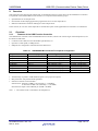
Features of the USB Function Controller
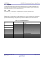
The USB function controller of the V850E2/MN4 microcontroller, which is the control target of this sample driver, has
the features listed below.
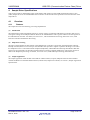
• Conforms to the USB (Universal Serial Bus Specification) 2.0.
• Operates as a full-speed (12 Mbps) device.
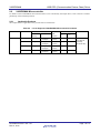
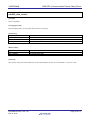
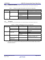
• Endpoints are configured as summarized in the table below.
Table 2.1
Endpoint Name
Endpoint0 Read
Endpoint0 Write
Endpoint1
Endpoint2
Endpoint3
Endpoint4
Endpoint7
Endpoint8
V850E2/MN4 Microcontroller’s Endpoint Configuration
FIFO Size (Bytes)
64
64
64 × 2
64 × 2
64 × 2
64 × 2
64
64
Transfer Type
Control transfer (IN)
Control transfer (OUT)
Bulk transfer 1 (IN)
Bulk transfer 1 (OUT)
Bulk transfer 2 (IN)
Bulk transfer 2 (OUT)
Interrupt transfer (IN)
Interrupt transfer (IN)
Remarks
⎯
⎯
2-buffer configuration
2-buffer configuration
2-buffer configuration
2-buffer configuration
⎯
⎯
• Automatically responds to USB standard requests (except part of requests)
• Bus-powered or self-powered mode selectable
• Internal or external clock selectable *1
Internal clock: External 9.6 MHz × 20 (internally) ÷ 4 (48 MHz)
or External 7.2 MHz × 20 (internally) ÷ 3 (48 MHz)
External clock: Input to the USBCLK pin (fUSB = 48 MHz)
Note: 1. The internal clock is selected for the sample driver.
R01AN0010EJ0101 Rev.1.01
Feb 01, 2012
Page 3 of 117
V850E2/MN4
2.1.2
USB CDC (Communication Device Class) Driver
Features of the Sample Driver
The CDC (Communication Device Class) sample driver for the V850E2/MN4 microcontroller has the features listed
below. For details about the features and operations of the sample driver, see section 4, Sample Driver Specifications.
• Conforms to the USB Communication Device Class Version 1.1 Abstract Control Model
• Operates as a virtual COM device
• Occupies memory areas of the following sizes (excluding that of the vector table):
ROM: Approx. 4.6 Kbytes
RAM: Approx. 0.8 Kbytes
2.1.3
Sample Driver Configuration
The sample driver is available in three versions, i.e., the CubeSuite version, the Multi version, and the IAR Embedded
Workbench. Use the correct version of the sample driver according to your development environment.
Each version of the sample driver is made up of the files that are described below.
(1)
CubeSuite Version
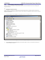
The CubeSuite version of the sample driver comprises files that are summarized below.
Table 2.2
Folder
src
CubeSuite Version Sample Driver File Configuration
File
main.c
usbf850.c
usbf850_communication.c
cstart.asm
main.h
usbf850.h
usbf850_communication.h
usbf850_desc.h
usbf850_errno.h
usbf850_types.h
reg_v850e2mn4.h
XXX_CDC_VISTA.inf
Outline
Main routine, initialization, sample application
USB initialization, endpoint control, bulk transfer, and control transfer
CDC-specific processing
Bootstrap
include
main.c function prototype declarations
usbf850.c function prototype declarations
usbf850_communication.c function prototype declarations
Descriptor definitions
Error code definitions
User type declarations
USB function register definitions
Inf
Windows® Vista® .inf file
The names of the microcontrollers are inserted in the sections
marked “****”: MN4
XXX_CDC_WIN7.inf
Windows 7® .inf file
The names of the microcontrollers are inserted in the sections
marked “****”: MN4
XXX_CDC_XP.inf
Windows XP® .inf file
The names of the microcontrollers are inserted in the sections
marked “****”: MN4
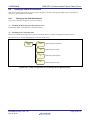
Remarks: The sample driver package comes also with a set of project-related files for the CubeSuite
(Renesas Electronics’ integrated development tool suit). For further information, see section 6.2.1,
Setting up the Host Environment.
R01AN0010EJ0101 Rev.1.01
Feb 01, 2012
Page 4 of 117
V850E2/MN4
(2)
USB CDC (Communication Device Class) Driver
Multi Version
The Multi version of the sample driver comprises files that are summarized below.
Table 2.3
Folder
src
Multi Version Sample Driver File Configuration
File
main.c
usbf850.c
usbf850_communication.c
initial.s
vector.s
main.h
usbf850.h
usbf850_communication.h
usbf850_desc.h
usbf850_errno.h
usbf850_types.h
reg_v850e2mn4.h
df3512_800.h
XXX_CDC_VISTA.inf
Outline
Main routine, initialization, sample application
USB initialization, endpoint control, bulk transfer, and control transfer
CDC-specific processing
Bootstrap
Interrupt vector table declarations
include
main.c function prototype declarations
usbf850.c function prototype declarations
usbf850_communication.c function prototype declarations
Descriptor definitions
Error code definitions
User type declarations
USB function register definitions
V850E2/MN4 register definitions
Inf
Windows® Vista® .inf file
The names of the microcontrollers are inserted in the sections
marked “****”: MN4
XXX_CDC_WIN7.inf
Windows 7® .inf file
The names of the microcontrollers are inserted in the sections
marked “****”: MN4
XXX_CDC_XP.inf
Windows XP® .inf file
The names of the microcontrollers are inserted in the sections
marked “****”: MN4
Remarks: The sample driver package comes also with a set of project-related files for the Multi (Green Hills
Software™, Inc. integrated development tool suit). For further information, see section 6.4.1,
Setting up the Host Environment.
R01AN0010EJ0101 Rev.1.01
Feb 01, 2012
Page 5 of 117
V850E2/MN4
(3)
USB CDC (Communication Device Class) Driver
IAR Embedded Workbench Version
The IAR Embedded Workbench version of the sample driver comprises files that are summarized below.
Table 2.4
Folder
src
IAR Embedded Workbench Version Sample Driver File Configuration
File
main.c
usbf850.c
usbf850_communication.c
main.h
usbf850.h
usbf850_communication.h
usbf850_desc.h
usbf850_errno.h
usbf850_types.h
reg_v850e2mn4.h
XXX_CDC_VISTA.inf
Outline
Main routine, initialization, sample application
USB initialization, endpoint control, bulk transfer, and control transfer
CDC-specific processing
include
main.c function prototype declarations
usbf850.c function prototype declarations
usbf850_communication.c function prototype declarations
Descriptor definitions
Error code definitions
User type declarations
USB function register definitions
Inf
Windows® Vista® .inf file
The names of the microcontrollers are inserted in the sections
marked “****”: MN4
XXX_CDC_WIN7.inf
Windows 7® .inf file
The names of the microcontrollers are inserted in the sections
marked “****”: MN4
XXX_CDC_XP.inf
Windows XP® .inf file
The names of the microcontrollers are inserted in the sections
marked “****”: MN4
Remarks: The sample driver package comes also with a set of project-related files for the IAR Embedded
Workbench. For further information, see section 6.6.1, Setting up the Host Environment.
R01AN0010EJ0101 Rev.1.01
Feb 01, 2012
Page 6 of 117
V850E2/MN4
2.2
USB CDC (Communication Device Class) Driver
V850E2/MN4 Microcontroller
For details on the V850E2/MN4 microcontroller that is to be controlled by the sample driver, refer to the user’s manual
[hardware] of the individual products.
2.2.1
Applicable Products
The sample driver is applicable to the products that are listed below.
Table 2.5
Model Name
List of Supported V850E2/MN4 Microcontroller Products
Part Number
Internal Memory
Flash
μ PD70F3510
1 Mbytes
Interrupt
USB
Internal
Function
Note 1
64 Kbytes
+ 64 Kbytes
Host and
Function
180
RAM
Memory
V850E2/MN4
Internal
UM
External
Note 1
29
V850E2/MN4
User’s Manual
μ PD70F3512
1 Mbytes
64 Kbytes
+ 64 Kbytes
Host and
Function
190
29
μ PD70F3514
1 Mbytes
64 Kbytes × 2
+ 64 Kbytes
Host and
Function
196
29
μ PD70F3515
2 Mbytes
64 Kbytes × 2
+ 64 Kbytes
Host and
Function
196
29
[Hardware]
(R01UH0011EJ)
Note: 1. Includes nonmaskable interrupts
R01AN0010EJ0101 Rev.1.01
Feb 01, 2012
Page 7 of 117
V850E2/MN4
2.2.2
USB CDC (Communication Device Class) Driver
Features
The major features of the V850E2/MN4 are listed below.
• Internal memory
RAM: Single core, 64 Kbytes; Dual core, 64 Kbytes × 2
Flash memory: 1 Mbyte
• Flash cache memory
Single core: 16 Kbytes (4-way associative)
Dual core: 16 Kbytes (4-way associative) × 2
• External bus interface
Equipped with 2 systems of memory controllers.
Primary memory controller (SRAM/SDRAM connectable)
Secondary memory controller (SRAM/SDRAM connectable)
• Serial interfaces
Asynchronous serial interface UART: 6 channels
Clock synchronous serial interface CSI: 6 channels
Asynchronous serial interface UART (FIFO): 4 channels
Clock synchronous serial interface CSI (FIFO): 4 channels
I2C: 6 channels
CAN: 2 channels (μPD70F3512, μPD70F3514, and μPD70F3515)
USB function controller: 1 channel
USB host controller: 1 channel
Ethernet controller: 1 channel (μPD70F3512, μPD70F3514, and μPD70F3515)
• DMA controllers
DMA controller: 16 channels
DTS: 128 channels maximum
R01AN0010EJ0101 Rev.1.01
Feb 01, 2012
Page 8 of 117
V850E2/MN4
3.
USB CDC (Communication Device Class) Driver
USB Overview
This section provides a brief description of the USB standard to which the sample driver conforms.
USB (Universal Serial Bus) is a standard for interfacing various peripheral devices with a host computer with a
common connector. It provides an interface that is more flexible and easier to use than conventional interfaces. For
example, it supports the hot-plug feature and allows a maximum of 127 devices to be connected together through the
use of additional connection nodes called hubs. The ratio of the PCs having the USB interface installed to the entire PCs
that are presently available is reaching almost 100%. It can safely be said that the USB interface has become the
standard interface for connecting the PC and peripheral devices.
The USB standard is formulated and managed by the organization called the USB Implementers Forum (USB-IF). For
details on the USB standard, visit the USB-IF’s official web site (www.usb.org).
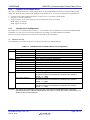
3.1
Transfer Modes
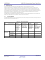
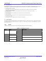
The USB standard defines four types of transfer modes (control, bulk, interrupt, and isochronous). The major features of
the transfer modes are summarized in table 3.1.
Table 3.1
Transfer Mode Control
Transfer
Item
Feature
Transfer mode
that is used to
exchange
information
necessary for
controlling
peripheral
devices.
64 bytes
Allowable
High speed
packet size
(480 Mbps)
Full speed
8, 16, 32, or 64
(12 Mbps)
bytes
8 bytes
Low speed
(1.5 Mbps)
Transfer priority
3
R01AN0010EJ0101 Rev.1.01
Feb 01, 2012
USB Transfer Modes
Bulk Transfer
Transfer mode
that is used to
handle a large
amount of data
nonperiodically.
Interrupt
Transfer
Transfer mode
that is used to
transfer data
periodically and
has a narrow
band width.
Isochronous
Transfer
Transfer mode
used in
applications that
are required of
high realtime
performance.
512 bytes
1 to 1024 bytes
1 to 1024 bytes
8, 16, 32, or 64
bytes
—
1 to 64 bytes
1 to 1023 bytes
1 to 8 bytes
—
3
2
1
Page 9 of 117
V850E2/MN4
3.2
USB CDC (Communication Device Class) Driver
Endpoints
An endpoint is an item of information used by the host device to identify a specific communication counterpart. An
endpoint is specified by a number from 0 to 15 and the direction (IN or OUT). An endpoint need be provided for each
data communication channel that is to be used by a peripheral device and cannot be shared by two or more
communication channels*1. For example, a device that has the capabilities to write and read to and from an SD card and
to print out data need be provided with an endpoint for writing to an SD card, an endpoint for reading from an SD card,
and an endpoint for sending data to a printer. Endpoint 0 is used for control transfer which must always be performed
by every device.
In data communication, the host device specifies the destination within the USB device using the USB device address
which identifies the device and an endpoint (number and direction).
A buffer memory is provided within every peripheral device as a physical circuit for endpoints. It also serves as a FIFO
that absorbs the difference in communication speed between the USB and the communication counterpart (e.g.,
memory).
Note: 1. There is a method of switching channels exclusively using a mechanism called the alternate setting.
3.3
Classes
Peripheral devices (function devices) connected via the USB have various classes defined according to their
functionality. Typical classes include the mass storage class (MSC), communication device class (CDC), and human
interface device class (HID). For each class, standard specifications are defined in the form of protocols. A common
host driver can be used provided that it conforms to those standard specifications.
The communication device class (CDC) is a class for communication equipment connected to a host computer. It is
used for devices such as modems, FAX equipment, and network cards. Since RS-232C interfaces are no longer
provided as standard equipment on personal computers, the CDC is often used for devices that implement USB serial
conversion when performing UART communication with a PC. Note that there are several models defined depending
on the mounted equipment. Of these, this sample driver uses the Abstract Control Model.
R01AN0010EJ0101 Rev.1.01
Feb 01, 2012
Page 10 of 117
V850E2/MN4
3.4
USB CDC (Communication Device Class) Driver
Requests
According to the USB specification, communication is initiated by the host device issuing a command called a request
to all function devices. The request contains data such as the direction and type of processing and the address of the
target function device. Each function device decodes the request, determines whether the request is directed to itself,
and responds to the request only when it is directed to the device.
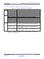
3.4.1
Types
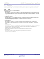
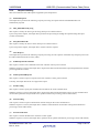
There are three types of requests, namely, the standard requests, class requests, and vendor requests.
See section 4.1.2, Requests Handling, for the requests that the sample driver support.
(1)
Standard Requests
Standard requests are used in common by all USB compatible devices. A request is a standard request when both bits 6
and 5 of the bmRequestType field of the request are set to 0. Refer to the USB specification (Universal Serial Bus
Specification Rev. 2.0) for the processing that is to be performed for the standard requests.
Table 3.2
Request Name
GET_STATUS
List of Standard Requests
Target Descriptor
Device
GET_DESCRIPTOR
SET_DESCRIPTOR
GET_CONFIGURATION
SET_CONFIGURATION
GET_INTERFACE
Endpoint
Device
Endpoint
Device
Endpoint
Device, configuration, string
Device, configuration, string
Device
Device
Interface
SET_INTERFACE
SET_ADDRESS
SYNCH_FRAME
Interface
Device
Endpoint
CLEAR_FEATURE
SET_FEATURE
R01AN0010EJ0101 Rev.1.01
Feb 01, 2012
Outline
Read power (self or bus) and remote wakeup
settings.
Read Halt status.
Clear remote wakeup.
Cancel Halt (DATA PID = 0).
Set up remote wakeup or test mode.
Set Halt
Read target descriptor
Set target descriptor (optional)
Read current configuration value.
Set configuration value.
Read alternate value out of the current settings
of the target interface.
Set alternate value of the target interface.
Set USB address.
Read frame-synchronous data.
Page 11 of 117
V850E2/MN4
(2)
USB CDC (Communication Device Class) Driver
Class Requests
Class requests are unique to the device class. Response processing for class requests corresponding to the CDC abstract
control model is implemented in the sample driver. The sample driver can respond to the following requests.
• Send Encapsulated Command
This request is used to issue commands in the communication class interface control protocol format.
• Get Encapsulated Command
This request requests a response in the communication class interface control protocol format.
• Set Line Coding
This request specifies the communications format for the serial communication.
• Get Line Coding
This request is used to acquire the current communication format setting at the device.
• Set Control Line State
This request is used for the RS-232/V.24 format control signals.
(3)
Vendor Requests
The vendor requests are defined uniquely by the individual vendors. A vendor who is to use a vendor request needs to
provide a host driver that handles that request. A request is a vendor request when bit 6 of the bmRequestType field is
set to 1 and bit 5 to 0.
3.4.2
Format
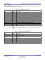
A USB request is 8 bytes long and consists of the fields that are listed in the table below.
Table 3.3
Offset
0
Field
bmRequestType
Bit 7
Bits 6 and 5
Bits 4 to 0
1
2
3
4
5
6
7
bRequest
wValue
wIndex
wLength
R01AN0010EJ0101 Rev.1.01
Feb 01, 2012
Lower
Upper
Lower
Upper
Lower
Upper
USB Request Format
Description
Request attribute
Data transfer direction
Request type
Target descriptor
Request code
Arbitrary value used in the request
Index or offset used in the request
Number of bytes to transfer in data stage (data length)
Page 12 of 117
V850E2/MN4
3.5
USB CDC (Communication Device Class) Driver
Descriptors
In the USB specification, a set of information that is specific to a function device and is encoded in a predetermined
format is called a descriptor. Each function device sends its descriptor in response to a request from the host device.
3.5.1
Types
The following five types of descriptors are defined:
• Device descriptor
This descriptor is present in all types of devices. It contains basic information such as the version of the supported
USB specification, device class, protocol, maximum packet length available for transfer to Endpoint0, vendor ID,
and product ID.
The descriptor must be sent in response to a GET_DESCRIPTOR_Device request.
• Configuration descriptor
Every device has one or more configuration descriptors. It contains such information as device attributes (power
supplying method) and power consumption. The descriptor must be sent in response to a
GET_DESCRIPTOR_Configuration request.
• Interface descriptor
This descriptor is necessary for each interface. It contains an interface ID, interface class, and the number of
endpoints that are supported. The descriptor must be sent in response to a GET_DESCRIPTOR_Configuration
request.
• Endpoint descriptor
This descriptor is necessary for each endpoint that is specified in the interface descriptor. It defines the transfer type
(direction of transfer), maximum packet length available for transfer to the endpoint, and transfer interval.
Endpoint0, however, does not have this descriptor.
The descriptor must be sent in response to a GET_DESCRIPTOR_Configuration request.
• String descriptor
This descriptor contains an arbitrary string. The descriptor must be sent in response to a
GET_DESCRIPTOR_String request.
R01AN0010EJ0101 Rev.1.01
Feb 01, 2012
Page 13 of 117
V850E2/MN4
3.5.2
USB CDC (Communication Device Class) Driver
Formats
The size and field structure of descriptors varies depending on the descriptor type as summarized in the tables below.
The data in each field is arranged in little endian format.
Table 3.4
Device Descriptor Format
Size
Field
(Bytes)
Description
bLength
1
Size of the descriptor
bDescriptorType
1
Type of the descriptor
bcdUSB
2
Release number of the USB specification
bDeviceClass
1
Class code
bDeviceSubClass
1
Subclass code
bDeviceProtocol
1
Protocol code
bMaxPacketSize0
1
Maximum packet size of Endpoint0
idVendor
2
Vendor ID
idProduct
2
Product ID
bcdDevice
2
Device release number
iManufacturer
1
Index of the string descriptor describing the manufacturer
iProduct
1
Index of the string descriptor describing the product
iSerialNumber
1
Index of the string descriptor describing the device’s serial number
bNumConfigurations
1
Number of configurations
Remarks: Vendor ID: Identification number that the vendor who is to develop a USB device acquires from
USB-IF
Product ID: Identification number that the vendor assigns to each of its products after acquiring a
vendor ID.
Table 3.5
Field
bLength
bDescriptorType
wTotalLength
Size
(Bytes)
1
1
2
bNumInterfaces
bConfigurationValue
iConfiguration
bmAttributes
bMaxPower
1
1
1
1
1
R01AN0010EJ0101 Rev.1.01
Feb 01, 2012
Configuration Descriptor Format
Description
Size of the descriptor
Type of the descriptor
Total number of bytes of the configuration, interface, and endpoint
descriptors
Number of interfaces supported by this configuration
Identification number of this configuration
Index of the string descriptor describing this configuration
Characteristics of this configuration
Maximum consumption current of this configuration (in 2 μA units)
Page 14 of 117
V850E2/MN4
USB CDC (Communication Device Class) Driver
Table 3.6
Field
bLength
bDescriptorType
bInterfaceNumber
bAlternateSetting
bNumEndpoints
bInterfaceClass
bInterfaceSubClass
bInterfaceProtocol
iInterface
Size
(Bytes)
1
1
1
1
1
1
1
1
1
Description
Size of the descriptor
Type of the descriptor
Identification number of this interface
Presence or absence of alternate setting for this interface
Number of endpoints used by this interface
Class code
Subclass code
Protocol code
Index of the string descriptor describing this interface
Table 3.7
Field
bLength
bDescriptorType
bEndpointAddress
Size
(Bytes)
1
1
1
bmAttributes
wMaxPacketSize
bInterval
1
2
1
Size
(Bytes)
1
1
Arbitrary
R01AN0010EJ0101 Rev.1.01
Feb 01, 2012
Endpoint Descriptor Format
Description
Size of the descriptor
Type of the descriptor
Transfer direction of this endpoint
Address of this endpoint
Transfer type of this endpoint
Maximum packet size available for transfer at this endpoint
Interval for polling this endpoint
Table 3.8
Field
bLength
bDescriptorType
bString
Interface Descriptor Format
String Descriptor Format
Description
Size of the descriptor
Type of the descriptor
Arbitrary data string
Page 15 of 117
V850E2/MN4
4.
USB CDC (Communication Device Class) Driver
Sample Driver Specifications
This section contains a detailed description of the features and operations of the USB communication device class
(CDC) sample driver for the V850E2/MN4 microcontroller. It also describes the specifications for the functions of the
sample driver.
4.1
Overview
4.1.1
Features
The sample driver has the following processing implemented:
(1)
Initialization
The initialization routine manipulates and sets up various registers to make the USB function controller ready for use.
The register settings are broadly divided into those for the V850E2/MN4’s CPU registers and those for the registers of
the USB function controller. For details, see section 4.2.1, CPU Initialization Processing, and section 4.2.2, USB
Function Controller Initialization Processing.
(2)
Endpoint Processing
The state of the endpoints for data transfer in the USB function controller is reported by the INTUSFA0I1 interrupt.
Broadly classified, there are two interrupts: the CPUDEC interrupt when a request to perform decoding is received in
the sample driver for a control data transfer endpoint (Endpoint0), and the BKO1DT interrupt that indicates that data
has been received normally for the bulk OUT data transfer (reception) endpoint (Endpoint2). The request response is
made in the Endpoint0 processing. For details, see section 4.2.3, USBF Interrupt Processing (INTUSFA0I1).
(3)
Sample Application
The sample application reads the data in the bulk OUT data transfer (reception) endpoint and writes that read data
without modification to the bulk IN data transfer (transmission) endpoint. For details, see section 5, Sample Application
Specifications.
R01AN0010EJ0101 Rev.1.01
Feb 01, 2012
Page 16 of 117
V850E2/MN4
4.1.2
USB CDC (Communication Device Class) Driver
Request Handling
This section describes the USB requests supported by the sample driver.
(1)
Standard Requests
The sample driver performs the following response processing for requests that the V850E2/MN4 does not
automatically respond:
(a)
GET_DESCRIPTOR_string
This request is used by the host to get the string descriptor of a function device.
Upon receipt of this request, the sample driver performs the processing of sending the requested string descriptor
(control read transfer).
(b)
SET_DESCRIPTOR
This request is used by the host to set the descriptor of a function device.
Upon receipt of this request, the sample driver returns a STALL response.
(2)
Class Requests
The sample driver performs the following response processing for class requests of the bulk-only transport protocol for
the USB communication device class (CDC):
(a)
SendEncapsulatedCommand
This request is used to issue commands in the CDC interface control protocol format.
When this request is received, the sample driver acquires the data associated with the request and performs the transmit
processing (bulk IN transfer).
(b)
GetEncapsulatedResponse
This request is used to request a response in the CDC interface control protocol format.
Currently, the sample drive does not support this request.
(c)
SetLineCoding
This request is used to specify the communication format for the serial communication.
When this request is received, the sample driver acquires the data associated with the request, sets the communication
rate and other parameters and performs NULL packet transmission processing (control read transfer).
(d)
GetLineCoding
This request is used to acquire communication format setting for the serial communication.
When this request is received, the sample driver reads the communication rate and other settings and transmission
processing (control read transfer).
(e)
SetControlLineState
This request is used for the RS-232/V.24 format control signals.
When this request is received, the sample driver performs NULL packet transmission processing (control read transfer).
R01AN0010EJ0101 Rev.1.01
Feb 01, 2012
Page 17 of 117
V850E2/MN4
4.1.3
USB CDC (Communication Device Class) Driver
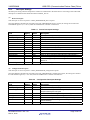
Descriptor Settings
The descriptor settings that the sample driver makes are summarized in the tables below. The settings of the individual
descriptors are defined in the header file named “usbf850_desc.h.”
(1)
Device Descriptor
This descriptor is sent in response to a GET_DESCRIPTOR_device request.
Since the hardware automatically responds to the GET_DESCRIPTOR_device request, the settings are stored in the
USFA0DDn registers (n = 0 to 17) when the USB function controller is initialized.
Table 4.1
Field
bLength
bDescriptorType
bcdUSB
bDeviceClass
bDeviceSubClass
bDeviceProtocol
bMaxPacketSize0
idVendor
idProduct
bcdDevice
iManufacturer
iProduct
iSerialNumber
Size
(Bytes)
1
1
2
1
1
1
1
2
2
2
1
1
1
Value
0x12
0x01
0x0200
0x02
0x00
0x00
0x40
0x045B
0x0200
0x0001
0x01
0x02
0x03
bNumConfigurations
1
0x01
(2)
Device Descriptor Settings
Description
Size of the descriptor: 18 bytes
Type of the descriptor: Device
USB specification release number: USB 2.0
Class code: CDC
Subclass code: None
Protocol code: No unique protocol used
Maximum packet size of Endpoint0: 64
Vendor ID: Renesas Electronics
Product ID: V850E2/MN4
Device release number: First version
Index of string descriptor describing the manufacturer: 1
Index of string descriptor describing the product: 2
Index of string descriptor describing the serial number of the
device: 3
Number of configurations: 1
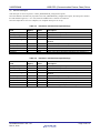
Configuration Descriptor
This descriptor is sent in response to a GET_DESCRIPTOR_configuration request.
Since the hardware automatically responds to the GET_DESCRIPTOR_configuration request, the settings are stored in
the USFA0CIEn registers (n = 0 to 255) when the USB function controller is initialized.
Table 4.2
Configuration Descriptor Settings
Field
bLength
bDescriptorType
wTotalLength
Size
(Bytes)
1
1
2
Value
0x09
0x02
0x0030
bNumInterfaces
bConfigurationValue
iConfiguration
bmAttributes
1
1
1
1
0x02
0x01
0x00
0x80
bMaxPower
1
0x1B
R01AN0010EJ0101 Rev.1.01
Feb 01, 2012
Description
Size of the descriptor: 9 bytes
Type of the descriptor: Configuration
Total number of bytes of the configuration, interface, and
endpoint descriptors: 48 bytes
Number of interfaces supported by this configuration: 2
Identification number of this configuration: 1
Index of the string descriptor describing this configuration: 0
Characteristics of this configuration: Bus powered, no
remote wakeup
Maximum consumption current of this configuration: 54 mA
Page 18 of 117
V850E2/MN4
(3)
USB CDC (Communication Device Class) Driver
Interface Descriptor
This descriptor is sent in response to a GET_DESCRIPTOR_configuration request.
Since the hardware automatically responds to the GET_DESCRIPTOR_configuration request, the settings are stored in
the USFA0CIEn registers (n = 0 to 255) when the USB function controller is initialized.
Since the sample driver uses two endpoints, two endpoint descriptors are set up.
Table 4.3
Interface 0 Interface Descriptor Settings
Field
bLength
bDescriptorType
bInterfaceNumber
bAlternateSetting
Size
(Bytes)
1
1
1
1
Value
0x09
0x04
0x00
0x00
bNumEndpoints
bInterfaceClass
bInterfaceSubClass
bInterfaceProtocol
iInterface
1
1
1
1
1
0x01
0x02
0x02
0x00
0x00
Table 4.4
Interface 1 Interface Descriptor Settings
Field
bLength
bDescriptorType
bInterfaceNumber
bAlternateSetting
Size
(Bytes)
1
1
1
1
Value
0x09
0x04
0x01
0x00
bNumEndpoints
bInterfaceClass
bInterfaceSubClass
bInterfaceProtocol
iInterface
1
1
1
1
1
0x02
0x0A
0x00
0x00
0x00
R01AN0010EJ0101 Rev.1.01
Feb 01, 2012
Description
Size of the descriptor: 9 bytes
Type of the descriptor: Interface
Identification number of this interface: 0
Presence or absence of alternate setting for this interface:
Absence
Number of endpoints used by this interface: 1
Class code: Communication interface class
Subclass code: Abstract Control Model
Protocol code: No unique protocol used
Index of the string descriptor describing this interface: 0
Description
Size of the descriptor: 9 bytes
Type of the descriptor: Interface
Identification number of this interface: 1
Presence or absence of alternate setting for this interface:
Absence
Number of endpoints used by this interface: 2
Class code: Communication interface class
Subclass code: Abstract Control Model
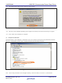
Protocol code: No unique protocol used
Index of the string descriptor describing this interface: 0
Page 19 of 117
V850E2/MN4
(4)
USB CDC (Communication Device Class) Driver
Endpoint Descriptor
This descriptor is sent in response to a GET_DESCRIPTOR_configuration request.
Since the hardware automatically responds to the GET_DESCRIPTOR_configuration request, the settings are stored in
the USFA0CIEn registers (n = 0 to 255) when the USB function controller is initialized.
Since the sample driver uses three endpoints, three endpoint descriptors are set up.
Table 4.5
Endpoint1 (Bulk IN) Endpoint Descriptor Settings
Field
bLength
bDescriptorType
bEndpointAddress
Size
(Bytes)
1
1
1
Value
0x07
0x05
0x81
bmAttributes
wMaxPacketSize
1
2
0x02
0x0040
bInterval
1
0x00
Table 4.6
Endpoint2 (Bulk OUT) Endpoint Descriptor Settings
Field
bLength
bDescriptorType
bEndpointAddress
Size
(Bytes)
1
1
1
Value
0x07
0x05
0x02
bmAttributes
wMaxPacketSize
1
2
0x02
0x0040
bInterval
1
0x00
Table 4.7
Description
Size of the descriptor: 7 bytes
Type of the descriptor: Endpoint
Transfer direction of this endpoint: OUT
Address of this endpoint: 2
Transfer type of this endpoint: Bulk
Maximum packet size available for transfer to this
endpoint: 64 bytes
Interval for polling this endpoint: 0 ms
Endpoint7 (Interrupt IN) Endpoint Descriptor Settings
Field
bLength
bDescriptorType
bEndpointAddress
Size
(Bytes)
1
1
1
Value
0x07
0x05
0x87
bmAttributes
wMaxPacketSize
1
2
0x03
0x0008
bInterval
1
0x0A
R01AN0010EJ0101 Rev.1.01
Feb 01, 2012
Description
Size of the descriptor: 7 bytes
Type of the descriptor: Endpoint
Transfer direction of this endpoint: IN
Address of this endpoint: 1
Transfer type of this endpoint: Bulk
Maximum packet size available for transfer to this
endpoint: 64 bytes
Interval for polling this endpoint: 0 ms
Description
Size of the descriptor: 7 bytes
Type of the descriptor: Endpoint
Transfer direction of this endpoint: IN
Address of this endpoint: 7
Transfer type of this endpoint: Interrupt
Maximum packet size available for transfer to this
endpoint: 8 bytes
Interval for polling this endpoint: 10 ms
Page 20 of 117
V850E2/MN4
(5)
USB CDC (Communication Device Class) Driver
String Descriptor
This descriptor is sent in response to a GET_DESCRIPTOR_string request.
When the sample driver receives a GET_DESCRIPTOR_string request, it fetches the string descriptor settings from the
header file named “usbf850_desc.h” and stores them in the USFA0E0W registers of the USB function controller.
Table 4.8
String Descriptor Settings
(a) String 0
Field
bLength
bDescriptorType
bString
Size
(Bytes)
1
1
2
Value
0x04
0x03
0x09, 0x04
Description
Size of the descriptor: 4 bytes
Type of the descriptor: String
Language code: English (U.S.)
(b) String 1
Size
Field
(Bytes)
Value
Description
1
bLength *
1
0x30
Size of the descriptor: 42 bytes
bDescriptorType
1
0x03
Type of the descriptor: String
bString *2
46
—
Vendor: Renesas Electronics Co.
Notes: 1. The value varies with the size of the bString field.
2. The size and value are not fixed because this area can be set up arbitrarily by the vendor.
(c) String 2
Size
Field
(Bytes)
Value
Description
bLength *1
1
0x0E
Size of the descriptor: 14 bytes
bDescriptorType
1
0x03
Type of the descriptor: String
bString *2
12
—
Product type: CDCDrv (CDC driver)
Notes: 1. The value varies with the size of the bString field.
2. The size and value are not fixed because this area can be set up arbitrarily by the vendor.
(d) String 3
Field
bLength *1
bDescriptorType
bString *2
Size
(Bytes)
1
1
22
Description
Size of the descriptor: 24 bytes
Type of the descriptor: String
Serial number:
V850E2/MN4: 020002020010
Notes: 1. The value varies with the size of the bString field.
2. The size and value are not fixed because this area can be set up arbitrarily by the vendor.
R01AN0010EJ0101 Rev.1.01
Feb 01, 2012
Value
0x16
0x03
—
Page 21 of 117
V850E2/MN4
4.2
USB CDC (Communication Device Class) Driver
Operations
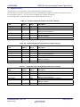
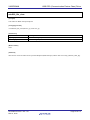
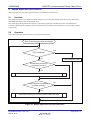
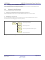
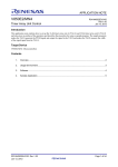
When the sample driver is started, it performs the sequence of processes that are illustrated in the figure below. This
section describes the individual processes.
Start
Initialize CPU
Initialize USB function controller
Execute sample application
Figure 4.1 Sample Driver Processing Flow
R01AN0010EJ0101 Rev.1.01
Feb 01, 2012
Page 22 of 117
V850E2/MN4
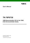
4.2.1
USB CDC (Communication Device Class) Driver
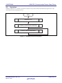
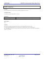
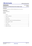
CPU Initialization Processing
The CPU initialization processing routine sets up the parameters that are necessary for using the USB function
controller.
Start of CPU
initialization
Enable HCLK output
H BUS initialization processing
Initialize USB clock
Initialize VBUS signal
End of CPU
initialization
Figure 4.2 CPU Initialization Processing Flow
(1)
Enabling HCLK Output
This process makes settings to enable the HCLK output so that the USBF connected to the H bus becomes enabled.
Since the SFRCTL2 register used for this setup is a specific write register, a specific write sequence is followed for the
setup.
(2)
H Bus Initialization
This process initializes the H-bus. The routine initializes the H bus according to the specified directions. See the
V850E2/MN4 Microcontroller User’s Manual [Hardware (R01UH0011EJ)].
(3)
Initializing USB Clock
This process sets up the multiplexed pin P13 to which UCLK is connected. This sample driver uses UCLK as the USB
clock input to the USB.
(4)
Initializing VBUS Signal
This process initializes the VBUS signal.
R01AN0010EJ0101 Rev.1.01
Feb 01, 2012
Page 23 of 117
V850E2/MN4
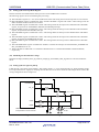
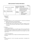
4.2.2
USB CDC (Communication Device Class) Driver
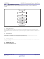
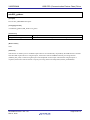
USB Function Controller Initialization Processing
The USB function controller initialization processing routine sets up the parameters necessary for starting the use of the
USB function controller.
Start of USB
initialization
Configure D+ signal for
no connection
Set up supply of UCLK
Initialize EPC circuit
Initialize USBF buffer
Set up NAK for control
endpoint
Initialize request data
register area
Set up interfaces and
endpoints
Reset NAK setting for
control endpoint
Initialize internal driver flags
Configure D+ signal for pull-up
End of USB
initialization
Figure 4.3 USB Function Controller Initialization Processing Flow
(1)
Configuring the D+ signal as Pull Down
Loads the CPU’s P4.10 with “0.” This sets the D+ signal low, disabling the host side to detect any device connection.
(2)
Setting up for the Supply of UCLK
Loads the SFRCTL3 register with “0x48” to enable the clock to be supplied to the USB function.
R01AN0010EJ0101 Rev.1.01
Feb 01, 2012
Page 24 of 117
V850E2/MN4
(3)
USB CDC (Communication Device Class) Driver
Initializing the EPC Circuit
Loads the USFA0EPCCTL register with “0x00000000” to cancel the EPC reset signal.
(4)
Initializing the USB Function Buffer
Loads the USFBC register with “0x00000003” to enable the USBF buffer and floating provisions.
(5)
Setting up NAK for Control Endpoint
Sets the EP0NKA bit of the USFA0E0NA register to 1. This setting causes the hardware to respond with NAK against
all requests including automatically responded requests.
This bit is used by the software until the registration of data to be used in automatically responded requests is completed,
so that the hardware will not return unintended data in response to an automatically responded request.
(6)
Initializing the Request Data Register Area
Loads relevant registers with descriptor data that is to be used to automatically respond to GET_DESCRIPTOR
requests.
The following registers are accessed during this processing:
(a) The USFA0DSTL register is loaded with “0x01.” This setting disables the remote wakeup function and the USB
function controller operates as a self-powered device.
(b) The USFA0EnSL registers (n = 0 to 2) are loaded with “0x00.” These settings indicate that the Endpoint n are
running normally.
(c) The USFA0DSCL register is loaded with the total length (in bytes) of the data in the necessary descriptors. This
setting determines the range of the USFA0CIEn registers (n = 0 to 255) to be used.
(d) The USFA0DDn registers (n = 0 to 7) are loaded with the data for the device descriptor.
(e) The USFA0CIEn registers (n = 0 to 255) are loaded with the data for the configuration, interface, and endpoint
descriptors.
(f) The USFA0MODC register is loaded with “0x00.” This setting enables GET_DESCRIPTOR_configuration
requests to be automatically responded.
(7)
Setting up the Interfaces and Endpoints
Loads relevant registers with the number of interfaces to support, alternate setting status, and the relationship between
the interfaces and endpoints.
The following registers are accessed during this processing:
(a) The USFA0AIFN register is loaded with “0x80.” This setting enables up to two interfaces.
(b) The USFA0AAS register is loaded with “0x00.” This setting disables the alternate setting.
(c) The USFA0E1IM register is loaded with “0x40.” This setting causes Endpoint1 to be linked to Interface1.
(d) The USFA0E2IM register is loaded with “0x40.” This setting causes Endopoint2 to be linked to Interface1.
(e) The USFA0E7IM register is loaded with “0x20.” This setting causes Endopoint7 to be linked to Interface0.
(8)
Resetting NAK Setting for Control Endpoint
Sets the EP0NKA bit of the USFA0E0NA register to 0. This setting enables the resumption of responses to all requests
including automatically responded requests.
R01AN0010EJ0101 Rev.1.01
Feb 01, 2012
Page 25 of 117
V850E2/MN4
(9)
USB CDC (Communication Device Class) Driver
Setting up the Interrupt Mask Register
Sets the mask bits associated with the interrupt sources of the USB function controller.
The following registers are accessed during this processing:
(a) The USFA0ICn registers (n = 0 to 4) are loaded with “0x00. This setting causes all interrupt sources to be cleared.
(b) The USFA0FIC0 register is loaded with “0xF7” and the USFA0FIC1 register with “0x0F.” These settings cause all
FIFOs available for data transfer to be cleared.
(c) The USFA0IM0 register is loaded with “0x1B.” This setting masks all interrupt sources defined in the USFA0IS0
register, except those for the BUSRST, RSUSPD, and SETRQ interrupts.
(d) The USFA0IM1 register is loaded with “0x7E.” This setting masks all interrupt sources defined in the USFA0IS1
register, except that for the CPUDEC interrupt.
(e) The USFA0IM2 register is loaded with “0xF1.” This setting masks all interrupt sources defined in the USFA0IS2
register.
(f) The USFA0IM3 register is loaded with “0xFE.” This setting masks all interrupt sources defined in the USFA0IS3
register, except that for the BKO1DT interrupt.
(g) The USFA0IM4 register is loaded with “0x20.” This setting masks all interrupt sources defined in the USFA0IS4
register.
(i) The USFA0EPCINTE register is loaded with “0x0003” to enable the interrupts for which the EPC_INT0BEN and
EPC_INT1BEN bits are set.
(j) The ICUSFA0I1 is loaded with “0” and the ICUSFA0I2 with “0” to enable INTUSFA0I1 and INTUSFA0I2,
respectively.
(10) Initializing the Internal Driver Flags
Initializes the flags (usbf850_busrst_flg, usbf850_rsuspd_flg, and usbf850_rdata_flg) that are to be used within the
driver.
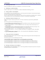
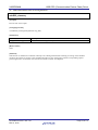
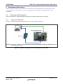
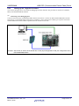
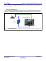
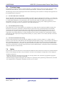
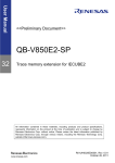
(11) Setting up the D+ signal as pull-up
Loads the CPU’s P4 register with “0x0400.” This setting causes a “1” to be output from P4_10, which generates a highlevel output from the D+ signal pin, notifying the host that a device has been connected. The sample driver assumes the
wiring configuration shown in figure 4.4.
UVDD
UVDD
INTUSFA0I1
P4_10
1.5 kΩ ± 5%
R1
VBUS
D+
UDPF
27 kΩ ± 5%
UDMF
USB function controller
incorporated in microcontroller
D27 kΩ ± 5%
R2
More than
50 kΩ
USB connector
Figure 4.4 USB Function Controller Configuration Example
R01AN0010EJ0101 Rev.1.01
Feb 01, 2012
Page 26 of 117
V850E2/MN4
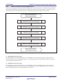
4.2.3
USB CDC (Communication Device Class) Driver
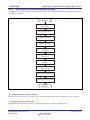
USBF Interrupt Processing (INTUSFA0I1)
Of the interrupt requests (INTUSFA0I1) from the USB function controller, only those for which the interrupt mask has
been cleared at initialization are reported. Therefore applications must clear the interrupt masks at initialization for all
required interrupts. For all reported interrupts, the corresponding required processing will be performed.
Start of INTUSFA0I1
interrupt processing
RSUSPD interrupt processing
BUSRST interrupt processing
SETRQ interrupt processing
CPUDEC interrupt processing
BKO1DT interrupt processing
End of INTUSFA0I1
interrupt processing
Figure 4.5 INTUSFA0I1 Interrupt Handler Processing Flow
(1)
RSUSPD Interrupt Processing
If the RSUSPD bit in the USFA0IS0 register is 1, the RSUSPDC bit in the USFA0IC0 register will be cleared to 0.
Next, if the RSUM bit in the USFA0EPS1 register is 1, the flag that indicates the suspend state (usbf850_rsuspd_flg)
will be updated (a suspend will occur).
(2)
BUSRST Interrupt Processing
If the BUSRST bit in the USFA0IS0 register is 1, the BUSRSTC bit in the USFA0IC0 register will be cleared to 0.
Next, the flag that indicates that a bus reset has occurred (usbf850_busrst_flg) is updated (a bus reset occurred), the
function usbf850_buff_init() is called and the buffer is initialized.
R01AN0010EJ0101 Rev.1.01
Feb 01, 2012
Page 27 of 117
V850E2/MN4
(3)
USB CDC (Communication Device Class) Driver
SETRQ Interrupt Processing
If the SETRQ bit in the USFA0IS0 register is 1, the SETRQC bit in the USFA0IC0 register will be cleared to 0. Next, if
both the SETCON bit in the USFA0SET register and the CONF bit in the USFA0MODS register are 1, the flag that
indicates that set configuration request was processed (usbf850_busrst_flg) is cleared.
(4)
CPUDEC Interrupt Processing
If the CPUDEC bit in the USFA0IS0 register is 1, the CPUDECC bit in the USFA0IC0 register will be cleared to 0.
Next, the USFA0E0ST register is read 8 times and the request data is acquired and decoded. If the request is a standard
request, the function usbf850_standardreq() is called and if it is a class request, the function usbf850_classreq() is called.
(5)
BKO1DT Interrupt Processing
If the BKODT bit in the USFA0IS3 register is 1, the BKODTC bit in the USFA0IC3 register will be cleared to 0. Next,
the flag that indicates that data has been received (usbf850_rdata_flg) is updated. This interrupt occurs if there is valid
data stored in the receive FIFO.
R01AN0010EJ0101 Rev.1.01
Feb 01, 2012
Page 28 of 117
V850E2/MN4
4.3
USB CDC (Communication Device Class) Driver
Function Specifications
This section describes the functions that are implemented in the sample driver.
4.3.1
List of Functions
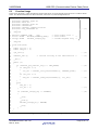
Table 4.9 shows a list of functions that are implemented in the source files for the sample driver.
Table 4.9
Source File
main.c
Sample Driver Functions
Function Name
main
cpu_init
SetProtectReg
Description
Main routine
Initializes the CPU.
Processes access to a write-protected
register.
usbf850.c
usbf850_init
Initializes the USB function controller.
usbf850_intusbf0
Monitors Endpoint0 and controls
responses to requests.
usbf850_intusbf1
Processes resume interrupts.
usbf850_data_send
Sends USB data.
usbf850_data_receive
Receives USB data.
usbf850_rdata_length
Gets USB receive data length.
usbf850_send_EP0
Sends at Endpoint0.
usbf850_receive_EP0
Receives at Endpoint0.
usbf850_send_null
Sends Null packets to Bulk/ Interrupt In
Endpoint.
usbf850_sendnullEP0
Sends out NULL packet for Endpoint0.
usbf850_sendstallEP0
Returns STALL for Endpoint0.
usbf850_ep_status
Notifies FIFO state of Bulk/ Interrupt In
Endpoint.
usbf850_fifo_clear
Clears FIFOs for endpoints other than
Endpoint0.
usbf850_standardreq
Processes a standard request.
usbf850_getdesc
Processes a GET_DESCRIPTOR
request.
usbf850_communication.c usbf850_classreq
Processes a CDC class request.
usbf850_send_encapsulated_command Processes a Send Encapsulated
Command request.
usbf850_get_encapsulated_response
Processes a Get Encapsulated
Command request.
usbf850_set_line_coding
Processes a Set Line Coding request.
usbf850_get_line_coding
Processes a Get Line Coding request.
usbf850_set_control_line_state
Processes a Set Control Line State
request.
usbf850_buff_init
FIFO clear processing for the endpoint
used for CDC data transmission
usbf850_get_bufinit_flg
Execution state notification processing
for FIFO initialization
usbf850_send_buf
CDC data send processing
usbf850_recv_buf
CDC class request processing function
registration
R01AN0010EJ0101 Rev.1.01
Feb 01, 2012
Page 29 of 117
V850E2/MN4
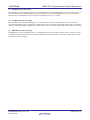
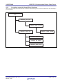
4.3.2
USB CDC (Communication Device Class) Driver
Correlation among the Sample Driver Functions
There are some sample driver functions that call another function during their execution. This function call relationships
are shown below.
main
usbf850_recv_buf
usbf850_data_receive
usbf850_send_buf
usbf850_rdata_length
usbf850_send_null
usbf850_ep_status
usbf850_data_send
Figure 4.6 Function Calls within main Processing
R01AN0010EJ0101 Rev.1.01
Feb 01, 2012
Page 30 of 117
V850E2/MN4
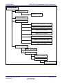
USB CDC (Communication Device Class) Driver
usbf850_intusbf0
usbf850_buff_init
usbf850_fifo_clear
usbf850_sendstallEP0
usbf850_classreq
usbf850_send_encapsulated_command
usbf850_get_encapsulated_response
usbf850_set_line_coding
usbf850_set_line_coding
usbf850_get_line_coding
usbf850_set_control_line_state
usbf850_sendstallEP0
usbf850_standardreq
usbf850_sendstallEP0
usbf850_getdesc
usbf850_sendstallEP0
usbf850_send_EP0
usbf850_sendstallEP0
Figure 4.7 Function Calls in USB Function Control Processing
R01AN0010EJ0101 Rev.1.01
Feb 01, 2012
Page 31 of 117
V850E2/MN4
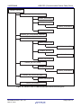
USB CDC (Communication Device Class) Driver
usbf850_classreq
usbf850_send_encapsulated_command
usbf850_sendstallEP0
usbf850_recieve_EP0
usbf850_sendstallEP0
usbf850_data_send
usbf850_get_encapsulated_response
usbf850_set_line_coding
usbf850_receive_EP0
usbf850_sendstallEP0
usbf850_buff_init
usbf850_fifo_clear
usbf850_sendnullEP0
usbf850_get_line_coding
usbf850_send_EP0
usbf850_sendstallEP0
usbf850_set_control_line_state
usbf850_sendnullEP0
usbf850_sendstallEP0
Figure 4.8 Function Calls in USB Communication Class Processing (1/2)
R01AN0010EJ0101 Rev.1.01
Feb 01, 2012
Page 32 of 117
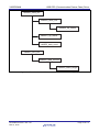
V850E2/MN4
USB CDC (Communication Device Class) Driver
usbf850_send_buf
usbf850_send_null
usbf850_ep_status
usbf850_ep_status
usbf850_data_send
usbf850_recv_buf
usbf850_data_receive
usbf850_rdata_length
Figure 4.9 Function Calls in USB Communication Class Processing (2/2)
R01AN0010EJ0101 Rev.1.01
Feb 01, 2012
Page 33 of 117
V850E2/MN4
4.3.3
USB CDC (Communication Device Class) Driver
Function Descriptions
This section contains a description of the functions that are implemented in the sample driver.
(1)
Functional Description Format
The functional descriptions are given in the format shown below.
Function Name
[Synopsis]
Gives a synopsis of the function.
[C language format]
Shows the format in C language
[Parameters]
Describes the parameters (arguments).
Parameter
Parameter type, name
Description
Parameter outline
[Return Value]
Describes the return value.
Symbol
Type of return value, name
Description
Return value outline
[Function]
Explains the function.
R01AN0010EJ0101 Rev.1.01
Feb 01, 2012
Page 34 of 117
V850E2/MN4
(2)
USB CDC (Communication Device Class) Driver
Main Routine Functions
main
[Synopsis]
Perform main processing.
[C language format]
void main(void)
[Parameters]
None
[Return Value]
None
[Function]
This function is called first when the sample driver is started.
The function initializes first the CPU and then the USB function controller. Next, it performs the sample application
processing and monitors the flag (usbf850_rsuspd_flg) that indicates that a suspend has occurred. If a suspend has
occurred, it performs suspend and resume processing at that point.
R01AN0010EJ0101 Rev.1.01
Feb 01, 2012
Page 35 of 117
V850E2/MN4
USB CDC (Communication Device Class) Driver
cpu_init
[Synopsis]
Initialize CPU.
[C language format]
void cpu_init(void)
[Parameters]
None
[Return Value]
None
[Function]
This function is called during initialization processing.
It initializes the H bus and sets up the USB clock and other parameters that are necessary to use the USB function
controller.
R01AN0010EJ0101 Rev.1.01
Feb 01, 2012
Page 36 of 117
V850E2/MN4
USB CDC (Communication Device Class) Driver
SetProtectReg
[Synopsis]
Access write-protected register.
[C language format]
void SetProtectReg(volatile UINT32 *dest_reg, UINT32 wr_dt, volatile UINT8 *prot_reg)
[Parameters]
Parameter
volatile UINT32 *dest_reg
UINT32 wr_dt
volatile UINT8 *prot_reg
Description
Protected register address
Write value
Protect command register address
[Return Value]
None
[Function]
This function writes a value into the given write-protected register.
R01AN0010EJ0101 Rev.1.01
Feb 01, 2012
Page 37 of 117
V850E2/MN4
(3)
USB CDC (Communication Device Class) Driver
USB Function Controller Processing Functions
usbf850_init
[Synopsis]
Initialize USB function controller.
[C language format]
void usbf850_init(void)
[Parameters]
None
[Return Value]
None
[Function]
This function is called during initialization processing.
It allocates and sets up the data area, and sets interrupt request masks and other parameter items that are necessary to
use the USB function controller.
R01AN0010EJ0101 Rev.1.01
Feb 01, 2012
Page 38 of 117
V850E2/MN4
USB CDC (Communication Device Class) Driver
usbf850_intusbf0
[Synopsis]
Endpoint0 monitor processing
Endpoint2 monitor processing
[C language format]
void usbf850_intusbf0(void)
[Parameters]
None
[Return Value]
None
[Function]
This function is an interrupt service routine that is called by the INTUSFA0I1 interrupt.
For USB function controller interrupts that are not masked, it verifies the details of the interrupt and processes the
interrupt that occurred.
R01AN0010EJ0101 Rev.1.01
Feb 01, 2012
Page 39 of 117
V850E2/MN4
USB CDC (Communication Device Class) Driver
usbf850_intusbf1
[Synopsis]
Resume interrupt processing
[C language format]
void usbf850_intusbf1(void)
[Parameters]
None
[Return Value]
None
[Function]
This function is an interrupt service routine that is called by the INTUSFA0I2 interrupt. It clears the flag that indicates
the suspend state and updates the resume flag.
R01AN0010EJ0101 Rev.1.01
Feb 01, 2012
Page 40 of 117
V850E2/MN4
USB CDC (Communication Device Class) Driver
usbf850_data_send
[Synopsis]
USB data transmit processing for bulk/interrupt in endpoints
[C language format]
INT32 usbf850_data_send(UINT8 *data, INT32 len, INT8 ep)
[Parameters]
Parameter
UINT8 *data
INT32 len
INT8 ep
Description
Pointer to transmit data buffer
Transmit data length
Endpoint number of the endpoint to be used for data transmission
[Return Value]
Symbol
len (>=0)
DEV_ERROR
Description
Size of the data that was transmitted normally.
Abnormal termination
[Function]
This function transfers data from the transmit data buffer to the FIFO for the specified endpoint, one byte at a time.
R01AN0010EJ0101 Rev.1.01
Feb 01, 2012
Page 41 of 117
V850E2/MN4
USB CDC (Communication Device Class) Driver
usbf850_data_receive
[Synopsis]
Receive USB data.
[C language format]
INT32 usbf850_data_receive(UINT8 *data, INT32 len, INT8 ep)
[Parameters]
Parameter
UINT8 *data
INT32 len
INT8 ep
Description
Pointer to receive data buffer
Receive data length
Endpoint number of the endpoint to be used for data reception
[Return Value]
Symbol
len (>=0)
DEV_ERROR
Description
Size of the data that was transmitted normally.
Abnormal termination
[Function]
This function reads data from the FIFO for the specified endpoint into the receive data buffer, one byte at a time.
R01AN0010EJ0101 Rev.1.01
Feb 01, 2012
Page 42 of 117
V850E2/MN4
USB CDC (Communication Device Class) Driver
usbf850_rdata_length
[Synopsis]
Get USB receive data length.
[C language format]
void usbf850_rdata_length(INT32 *len , INT8 ep)
[Parameters]
Parameter
INT32* len
INT8 ep
Description
Pointer to the address storing the receive data length
Endpoint number of the data receiving endpoint
[Return Value]
None
[Function]
This function reads the receive data length of the specified endpoint.
R01AN0010EJ0101 Rev.1.01
Feb 01, 2012
Page 43 of 117
V850E2/MN4
USB CDC (Communication Device Class) Driver
usbf850_send_EP0
[Synopsis]
Send USB data for Endpoint0.
[C language format]
INT32 usbf850_send_EP0(UINT8* data, INT32 len)
[Parameters]
Parameter
UINT8* data
INT32 len
Description
Pointer to transmit data buffer
Transmit data size
[Return Value]
Symbol
DEV_OK
DEV_ERROR
Description
Normal termination
Abnormal termination
[Function]
This function transfers data from the transmit data buffer to the transmit FIFO for Endpoint0, one byte at a time.
R01AN0010EJ0101 Rev.1.01
Feb 01, 2012
Page 44 of 117
V850E2/MN4
USB CDC (Communication Device Class) Driver
usbf850_receive_EP0
[Synopsis]
Receive USB data for Endpoint0.
[C language format]
INT32 usbf850_receive_EP0(UINT8* data, INT32 len)
[Parameters]
Parameter
UINT8* data
INT32 len
Description
Pointer to receive data buffer
Receive data size
[Return Value]
Symbol
DEV_OK
DEV_ERROR
Description
Normal termination
Abnormal termination
[Function]
This function reads data from the receive FIFO for Endpoint0 into the receive data buffer, one byte at a time.
R01AN0010EJ0101 Rev.1.01
Feb 01, 2012
Page 45 of 117
V850E2/MN4
USB CDC (Communication Device Class) Driver
usbf850_send_null
[Synopsis]
Send Null packet for Bulk/Interrupt In Endpoint.
[C language format]
INT32 usbf850_send_null(INT8 ep)
[Parameters]
Parameter
INT8 ep
Description
Endpoint number of the data transmitting endpoint
[Return Value]
Symbol
DEV_OK
DEV_ERROR
Description
Normal termination
Abnormal termination
[Function]
This function sends a Null packet from the USB function controller by clearing the FIFO for the specified Endpoint (for
transmission) and setting the bit that specifies the end of data to 1.
R01AN0010EJ0101 Rev.1.01
Feb 01, 2012
Page 46 of 117
V850E2/MN4
USB CDC (Communication Device Class) Driver
usbf850_sendnullEP0
[Synopsis]
Send NULL packet for Endpoint0.
[C language format]
void usbf850_sendnullEP0(void)
[Parameters]
None
[Return Value]
None
[Function]
This function sends a Null packet from the USB function controller by clearing the FIFO for Endpoint0 and setting the
bit that specifies the end of data to 1.
R01AN0010EJ0101 Rev.1.01
Feb 01, 2012
Page 47 of 117
V850E2/MN4
USB CDC (Communication Device Class) Driver
usbf850_sendstallEP0
[Synopsis]
Send STALL response for Endpoint0.
[C language format]
void usbf850_sendstallEP0(void)
[Parameters]
None
[Return Value]
None
[Function]
This function causes the USB function controller to return a STALL response by setting the bit that indicates the use of
a STALL handshake to 1.
R01AN0010EJ0101 Rev.1.01
Feb 01, 2012
Page 48 of 117
V850E2/MN4
USB CDC (Communication Device Class) Driver
usbf850_ep_status
[Synopsis]
Notify state of FIFO for Bulk/ Interrupt In Endpoint.
[C language format]
INT32 usbf850_ep_status(INT8 ep)
[Parameters]
Parameter
INT8 ep
Description
Endpoint number of the data transmitting endpoint
[Return Value]
Symbol
DEV_OK
DEV_RESET
DEV_ERROR
Description
Normal termination
Bus Reset processing in progress
Abnormal termination
[Function]
This function notifies the state of the FIFO for the specified Endpoint (for transmission).
R01AN0010EJ0101 Rev.1.01
Feb 01, 2012
Page 49 of 117
V850E2/MN4
USB CDC (Communication Device Class) Driver
usbf850_fifo_clear
[Synopsis]
Clear FIFO for Bulk/ Interrupt Endpoint.
[C language format]
void usbf850_fifo_clear(INT8 in_ep, INT8 out_ep)
[Parameters]
Parameter
INT8 in_ep
INT8 out_ep
Description
Data transmitting Endpoint
Data receiving Endpoint
[Return Value]
None
[Function]
This function clears the FIFO for the specified Endpoint (Bulk/Interrupt) and the data receive flag (usbf850_rdata_flg).
R01AN0010EJ0101 Rev.1.01
Feb 01, 2012
Page 50 of 117
V850E2/MN4
USB CDC (Communication Device Class) Driver
usbf850_standardreq
[Synopsis]
Process standard request not automatically responded by USB function controller.
[C language format]
void usbf850_standardreq(USB_SETUP *req_data)
[Parameters]
Parameter
USB_SETUP *req_data
Description
Pointer to the address storing the receive data length
[Return Value]
None
[Function]
Function that is called for the CPUDEC interrupt factor for INTUSFA0I1 interrupt processing.
It calls the GET_DESCRIPTOR request processing function (usbf850_getdesc) if the decoded request is
GET_DESCRIPTOR. For the other requests, the function calls the STALL response processing function for Endpoint0
(usbf850_sendstallEP0).
R01AN0010EJ0101 Rev.1.01
Feb 01, 2012
Page 51 of 117
V850E2/MN4
USB CDC (Communication Device Class) Driver
usbf850_getdesc
[Synopsis]
Process GET_DESCRIPTOR request.
[C language format]
void usbf850_getdesc(USB_SETUP *req_data)
[Parameters]
Parameter
USB_SETUP *req_data
Description
Pointer to the address storing the receive data length
[Return Value]
None
[Function]
This function is called to process standard requests that are not automatically responded by the USB function controller.
If the decoded request asks for a string descriptor, the function calls the USB data transmit processing function
(usbf850_data_send) to send a string descriptor from Endpoint0. If a descriptor other than the string descriptor is
requested, the function calls the STALL response processing function for Endpoint0 (usbf850_sendstallEP0).
R01AN0010EJ0101 Rev.1.01
Feb 01, 2012
Page 52 of 117
V850E2/MN4
(4)
USB CDC (Communication Device Class) Driver
USB Communication Class Processing Functions
usbf850_classreq
[Synopsis]
Process CDC class request.
[C language format]
void usbf850_classreq(USB_SETUP *req_data)
[Parameters]
Parameter
USB_SETUP *req_data
Description
Pointer to area storing the request data
[Return Value]
None
[Function]
This function is called for the CPUDEC interrupt source during INTUSFA0I1 interrupt processing. If the decoded
request is the one that is specific to the communication device class, the function calls the corresponding request
processing function. In the other cases, the function sends a STALL to Endpoint0.
R01AN0010EJ0101 Rev.1.01
Feb 01, 2012
Page 53 of 117
V850E2/MN4
USB CDC (Communication Device Class) Driver
usbf850_send_encapsulated_command
[Synopsis]
Send Encapsulated Command request processing
[C language format]
void usbf850_send_encapsulated_command(USB_SETUP *req_data)
[Parameters]
Parameter
USB_SETUP *req_data
Description
Pointer to area storing the request data
[Return Value]
None
[Function]
This function calls the data reception processing function (usbf850_data_receive()) to acquire the data received by
Endpoint0 and calls the data transmission processing function (usbf850_data_send()) to send that data by bulk in
transmission (send) from Endpoint2.
R01AN0010EJ0101 Rev.1.01
Feb 01, 2012
Page 54 of 117
V850E2/MN4
USB CDC (Communication Device Class) Driver
usbf850_set_line_coding
[Synopsis]
Set Line Coding request processing
[C language format]
void usbf850_set_line_coding(USB_SETUP *req_data)
[Parameters]
Parameter
USB_SETUP *req_data
Description
Pointer to area storing the request data
[Return Value]
None
[Function]
This function calls the data reception processing function (usbf850_data_receive()) to acquire the data received by
Endpoint0 and writes that data to a UART_MODE_INFO structure. Also, based on this value, it sets the transfer speed,
data length, and other aspects of the UART mode and then calls the Endpoint0 null packet transmit processing function
(usbf850_sendnullEP0()).
R01AN0010EJ0101 Rev.1.01
Feb 01, 2012
Page 55 of 117
V850E2/MN4
USB CDC (Communication Device Class) Driver
usbf850_get_line_coding
[Synopsis]
Get Line Coding request processing
[C language format]
void usbf850_get_line_coding(USB_SETUP *req_data)
[Parameters]
Parameter
USB_SETUP *req_data
Description
Pointer to area storing the request data
[Return Value]
None
[Function]
This function calls the data transmission processing function (usbf850_data_send()) to send the value of the
UART_MODE_INFO structure from Endpoint0.
R01AN0010EJ0101 Rev.1.01
Feb 01, 2012
Page 56 of 117
V850E2/MN4
USB CDC (Communication Device Class) Driver
usbf850_set_control_line_state
[Synopsis]
Set Control Line State request processing
[C language format]
void usbf850_set_control_line_state(USB_SETUP *req_data)
[Parameters]
Parameter
USB_SETUP *req_data
Description
Pointer to area storing the request data
[Return Value]
None
[Function]
This function calls the Endpoint0 null packet transmit processing function (usbf850_sendnullEP0()).
R01AN0010EJ0101 Rev.1.01
Feb 01, 2012
Page 57 of 117
V850E2/MN4
5.
USB CDC (Communication Device Class) Driver
Sample Application Specifications
This section describes the sample application that is included in the sample driver.
5.1
Overview
This sample application is provided as a simple example of use of the USB communication device class driver and is
embedded in the main routine of the sample driver.
This sample application performs the sequence of processing required to read data received by the USB function
controller and transmit that read data. It uses various functions provided by the sample driver to perform this sequence
of processing.
5.2
Operation
The sample application performs the flow of operation shown below.
Start of sample application processing
Yes
FIFO initialized?
No
Did transmit processing
complete normally?
Clear reception result
No
Yes
Reception processing for communication class user data
Did reception processing
complete normally?
No
Yes
Transmit processing for communication class user data
Figure 5.1 Sample Application Processing Flowchart
R01AN0010EJ0101 Rev.1.01
Feb 01, 2012
Page 58 of 117
V850E2/MN4
(1)
USB CDC (Communication Device Class) Driver
User Data FIFO Initialization Verification
The sample application calls user data FIFO status notification function (usbf850_get_bufinit_flg()). If the FIFO is in
the normal state it proceeds to transmit processing result verification, and if the FIFO is in the initialized state it clears
the transmission result (clears the CDC user data transmit result to 0).
(2)
CDC User Data Transmit Result Verification
If the CDC user data transmit result is normal completion (or initial state), the sample application performs CDC user
data reception processing, and if it is in an abnormal termination state, it verifies the result of reception processing.
(3)
CDC User Data Reception Processing
The sample application specifies the size of the buffer used to store the receive data and calls the CDC user data
reception processing function (usbf850_recv_buf()).
(4)
CDC User Data Reception Processing Result Verification
If the CDC user data receive result is normal completion (or initial state), the sample application performs CDC user
data transmission processing, and if it is in an abnormal termination state, it performs user data FIFO initialization
verification processing.
(5)
CDC User Data Transmission Processing
The sample application specifies the address of the buffer that holds the data to transmit and the size of the data to
transmit and calls the CDC user data transmission processing function (usbf850_send_buf()).
R01AN0010EJ0101 Rev.1.01
Feb 01, 2012
Page 59 of 117
V850E2/MN4
5.3
USB CDC (Communication Device Class) Driver
Function Usage
In the source file main.c, which includes the sample application, use of the sample driver functions is coded as shown
below. For detailed information on these functions, see section 4.3, Function Specifications.
1
2
3
4
5
6
7
8
9
10
11
12
13
14
15
#pragma ioreg
#include "usbf850_types.h"
#include “main.h"
#include “usbf850_errno.h"
#include “usbf850.h"
#include “usbf850_communication.h"
#include "reg_v850e2mn4.h"
:
omitted
:
#define USERBUF_SIZE
(64)
static UINT8
UserBuf[USERBUF_SIZE];
extern UINT8
usbf850_rsuspd_flg;
:
omitted
:
void main(void)
{
INT32 rcv_ret = 0;
INT32 snd_ret = 0;
···(1)
/* user buffer size */
/* user buffer
/* resume/suspend flag
*/
*/
16
17
18
19
20
21 cpu_init();
22
23 usbf850_init();
/* initial setting of the USB Function */
24
25 __EI();
26
27 while (1)
28 {
29
if (usbf850_get_bufinit_flg() != DEV_ERROR)
30
{
31
if (snd_ret >= 0)
32
{
33
rcv_ret = usbf850_recv_buf(&UserBuf[0], USERBUF_SIZE);
34
}
35
if (rcv_ret >= 0)
36
{
37
snd_ret = usbf850_send_buf(&UserBuf[0], rcv_ret);
38
}
39
}
40
else
41
{
42
snd_ret = 0;
43
rcv_ret = 0;
44
}
45
46
if (usbf850_rsuspd_flg == SUSPEND)
47
{
48
49
__DI();
50
51
__halt();
52
53
usbf850_rsuspd_flg = RESUME;
54
55
__EI();
56
}
57 }
58 }
Figure 5.2 Sample Application Code (partial)
R01AN0010EJ0101 Rev.1.01
Feb 01, 2012
···(2)
···(3)
···(4)
···(5)
···(6)
···(7)
···(8)
Page 60 of 117
V850E2/MN4
(1)
USB CDC (Communication Device Class) Driver
Definitions and Declarations
The two header files usbf850.h and usbf850_communication.h are included so that the sample driver functions can be
used. Also, a user buffer with a size adequate for processing one packet of data is provided for user data (the maximum
packet size for bulk endpoints in USB full speed is 64 bytes).
(2)
CPU Initialization
The CPU initialization function (cpu_init()) is called.
(3)
USB Function Controller Initialization
The USB function controller initialization function (usbf850_init()) is called.
(4)
User Data FIFO State Verification
The FIFO state is verified by calling the user data FIFO state reporting function (usbf850_get_bufinit_flg()).
(5)
User Data Reception Processing
The CDC user data reception processing function (usbf850_recv_buf()) is called and the result saved.
(6)
User Data Transmission Processing
The CDC user data transmission processing function (usbf850_send_buf()) is called and the result saved.
(7)
Clearing the Transmit/Receive Results
The transmit and receive results saved in (5) and (6) are cleared to zero when the user data FIFO is initialized.
(8)
Suspend and Resume Processing
The flag (usbf850_rsuspd_flg) that indicates that a suspend has occurred is monitored. If a suspend has occurred, the
__halt() function is called to transition to the HALT state. A resume is performed in response to an external interrupt,
and the flag (usbf850_rsuspd_flg) that indicates that a suspend has occurred is set to the RESUME state and operation
restarts.
R01AN0010EJ0101 Rev.1.01
Feb 01, 2012
Page 61 of 117
V850E2/MN4
6.
USB CDC (Communication Device Class) Driver
Development Environment
This section gives an example of constructing an environment for developing application programs using the USB
communication device class sample driver for the V850E2/MN4 and the procedures for debugging them in that
environment.
6.1
Development Environment
This section introduces a sample development configuration of hardware and software tool products.
6.1.1
System Configuration
The system configuration in which the sample driver is to be used is shown in figure 6.1.
Host machine
Remarks: See section 8, Outline of the Starter Kit, for the physical appearance and port configuration of the
RTE-V850E2/MN4-EB-S.
Figure 6.1 System Configuration of the Development Environment
R01AN0010EJ0101 Rev.1.01
Feb 01, 2012
Page 62 of 117
V850E2/MN4
6.1.2
USB CDC (Communication Device Class) Driver
Program Development
The hardware and software that are summarized below are required to develop a system using the sample driver.
Table 6.1
Example of Program Development Environment Configuration
Component Products
Hardware
Host machine
Product Example
⎯
Software
CubeSuite
Multi
IAR Embedded
Workbench
CX850
CCV850
ICCV850
Integrated development
tool
Compiler
6.1.3
Remarks
PC/AT™ compatible
(OS: Windows XP or Windows Vista®)
V1.40
V5.1.7D
V3.71
V1.00
V5.1.7D
V3.71.2
Debugging
The hardware and software that are summarized below are required to debug a system using the sample driver.
Table 6.2
Example of Debugging Environment Configuration
Component Products
Hardware
Host machine
Product Example
⎯
Target
USB cable
RTE-V850E2/MN4-EB-S
⎯
Software
Integrated development
tool/debugger
File
Device file
CubeSuite
Multi
IAR Embedded
Workbench
DF703512
Remarks
PC/AT compatible
(OS: Windows XP or Windows Vista®)
Manufactured by MIDAS LAB
Connection between B receptacle to
A receptacle
V1.40
V5.1.7D
V3.71
For V850E2/MN4 (separately
available for CubeSuite, Multi, and
IAR Embedded Workbench)
Note1
⎯
Host driver for
debugging port
Note2
Project-related file
⎯
Notes: 1. Contact Renesas for product and ordering information.
2. The sample driver package comes with sample files that are built with CubeSuite, Multi, and IAR
Embedded Workbench.
R01AN0010EJ0101 Rev.1.01
Feb 01, 2012
Page 63 of 117
V850E2/MN4
6.2
USB CDC (Communication Device Class) Driver
Setting up a CubeSuite Environment
This section explains the preparatory steps that are required to develop or debug using CubeSuite which is introduced in
section 6.1, Development Environment. See section 6.4, Setting up a Multi Environment, when using Multi for program
development and debugging. See section 6.6, Setting up IAR Embedded Workbench Environment, when using IAR
Workbench for program development and debugging.
6.2.1
Setting up the Host Environment
You create a dedicated workspace on the host machine.
(1)
Installing the CubeSuite Integrated Development Tools
Install CubeSuite. Refer to the CubeSuite user’s manual for details.
(2)
Expanding Driver and Other Files
Store a set of distribution sample driver files in an arbitrary directory without modifying their folder structure.
Store the host driver for the debugging port in an arbitrary directory.
Arbitrary
folder
include
Folder storing the include files
Inf
Folder storing the Inf files
prj
Folder storing CubeSuite projects
src
Folder storing source files
Figure 6.2 Folder Configuration for the Sample Driver (CubeSuite Version)
R01AN0010EJ0101 Rev.1.01
Feb 01, 2012
Page 64 of 117
V850E2/MN4
(3)
USB CDC (Communication Device Class) Driver
Installing Device Files
Copy the V850E2/MN4 device files for CubeSuite in the folder where CubeSuite is installed.
Example: D:\Renesas Electronics CubeSuite\CubeSuite\Device_Custom
Figure 6.3 Example of Destination Folder for Storing the Device Files
(4)
Setting up a Workspace
Follow the procedure given below when using the project-related files that come with the sample driver package.
<1>
Start CubeSuite and choose “Open” from the “File” menu.
Figure 6.4 Choosing a CubeSuite Menu Item
R01AN0010EJ0101 Rev.1.01
Feb 01, 2012
Page 65 of 117
V850E2/MN4
<2>
USB CDC (Communication Device Class) Driver
The “Open” dialog box will appear. Select the project file for CubeSuite which is located in the “prj” folder in
the directory in which the sample driver is installed.
Figure 6.5 Selecting the CubeSuite Project File
R01AN0010EJ0101 Rev.1.01
Feb 01, 2012
Page 66 of 117
V850E2/MN4
(5)
USB CDC (Communication Device Class) Driver
Setting up the Build Tool
Follow the procedure given below to select the version of CX850 which is to be used as the build tool and to designate
V850E2M MINICUBE as the debugging tool.
<1>
Select “CX (Build Tool)” from the “Project Tree” for CubeSuite to display its properties.
Figure 6.6 Selecting the Build Tool
<2>
Select the “Version Select” properties item and sets the “Using compiler package version” entry to “Always
latest version which was installed.”
Figure 6.7 Setting up the Compiler Package
R01AN0010EJ0101 Rev.1.01
Feb 01, 2012
Page 67 of 117
V850E2/MN4
<3>
USB CDC (Communication Device Class) Driver
Select “V850E2M MINICUBE (Debug Tool)” from the project tree and select “Using Debug Tool”
→ ”V850E2M MINICUBE” from the right-click menu.
Figure 6.8 Selecting the Debugging Tool
R01AN0010EJ0101 Rev.1.01
Feb 01, 2012
Page 68 of 117
V850E2/MN4
6.2.2
USB CDC (Communication Device Class) Driver
Setting up the Target Environment
You connect the target device to be used for debugging to the host machine. The procedure is common to CubeSuite,
Multi, and IAR Embedded Workbench.
(1)
Connecting to the Debugging Port
Connect between the RTE-V850E2/MN4-EB-S and the host machine. Connect the RTE-V850E2/MN4-EB-S and the
host machine via the MINICUBE for debugging. In addition, connect between the USB B type receptacle of the RTEV850E2/MN4-EB-S and the USB receptacle of the host machine for the CDC.
Host machine
Remarks: See section 8, Outline of the Starter Kit, for the physical appearance and port configuration of the
RTE-V850E2/MN4-EB-S.
Figure 6.9 Connecting the RTE-V850E2/MN4-EB-S
R01AN0010EJ0101 Rev.1.01
Feb 01, 2012
Page 69 of 117
V850E2/MN4
(2)
USB CDC (Communication Device Class) Driver
Host Driver Installation
This section presents the procedure for using the virtual COM port host driver included with this sample driver.
<1>
When connection of the RTE-V850E2/MN4-EB-S is recognized by the host machine, it displays the “New
hardware detected” message and starts the “Found New Hardware Wizard”.
<2>
The “Found New Hardware Wizard” dialog opens. Select, “No, not this time” and click “Next”.
Figure 6.10 Add New Hardware Wizard (1)
<3>
The next screen will be displayed. Select “Install from a list or specific location (Advanced)” and click “Next”.
Figure 6.11 Add New Hardware Wizard (2)
R01AN0010EJ0101 Rev.1.01
Feb 01, 2012
Page 70 of 117
V850E2/MN4
<4>
USB CDC (Communication Device Class) Driver
The next screen will be displayed. Select “Don’t search. I will choose the driver to install.” and click “Next”.
Figure 6.12 Add New Hardware Wizard (3)
<5>
The next screen will be displayed. Click “Have Disk”.
Figure 6.13 Add New Hardware Wizard (4)
R01AN0010EJ0101 Rev.1.01
Feb 01, 2012
Page 71 of 117
V850E2/MN4
<6>
USB CDC (Communication Device Class) Driver
The “Install From Disk” dialog will open. Click “Browse...” to display the inf file folder in the directory that
holds the sample driver.
Figure 6.14 Browsing for .inf Files
<7> Select the .inf file in the folder (XP, Vista, or Win7) that matches the OS used on the host system and click Open.
Figure 6.15 Selecting a .inf File
<8>
The system will return to the “Install From Disk” dialog. Verify that the file shown in the “Copy manufacturer’s
files from:” field is correct and click “OK”.
Figure 6.16 Installing the .inf File
R01AN0010EJ0101 Rev.1.01
Feb 01, 2012
Page 72 of 117
V850E2/MN4
<9>
USB CDC (Communication Device Class) Driver
The system will return to the “Found New Hardware Wizard”. Select “Renesas Electronics V850E2/MN4
Virtual UART” and click “Next”.
Figure 6.17 Selecting the Device Driver to Install
<10> The driver installation process will start.
Figure 6.18 Driver Installation in Progress (1)
R01AN0010EJ0101 Rev.1.01
Feb 01, 2012
Page 73 of 117
V850E2/MN4
USB CDC (Communication Device Class) Driver
<11> The “Hardware Installation” dialog will be displayed. Click “Continue Anyway”.
Figure 6.19 Driver Compatibility Verification Dialog
<12> The driver will be installed. Depending on the computer environment, some amount of time may be required.
<13> Click “Finish” after installation is completed.
(3)
Verify Device Allocation
Open the Windows “Device Manager”. Expand the “Ports” tree in the device listing and verify both that the “Renesas
Electronics V850E2/MN4 Virtual UART” is displayed and the allocated COM port number.
Figure 6.20 COM Port Verification
Note: Device and port numbers can be changed to arbitrary values. For details, see section 7.2, Customization.
R01AN0010EJ0101 Rev.1.01
Feb 01, 2012
Page 74 of 117
V850E2/MN4
6.3
USB CDC (Communication Device Class) Driver
Debugging in the CubeSuite Environment
This section explains the procedure to debug an application program that is developed in the workspace introduced in
section 6.2, Setting up the CubeSuite Environment.
6.3.1
Generating a Load Module
To write a program into the target device, it is necessary to compile its source file that is coded in C or assembly
language into a load module.
In CubeSuite, a load module is generated by choosing “Build Project” from the “Build” menu.
Figure 6.21 Selecting a Build Project
R01AN0010EJ0101 Rev.1.01
Feb 01, 2012
Page 75 of 117
V850E2/MN4
6.3.2
USB CDC (Communication Device Class) Driver
Loading and Executing
You write (load) the generated load module into the target for execution.
(1)
Writing a Load Module
Shown below is the procedure to write a load module into the RTE-V850E2/MN4-EB-S via CubeSuite.
<1>
Choose “Download” from the “Debug” menu and start the debugger.
Figure 6.22 Starting the Debugger
<2>
The downloading of the load module is started via the debugging tool.
Figure 6.23 Executing the Download
R01AN0010EJ0101 Rev.1.01
Feb 01, 2012
Page 76 of 117
V850E2/MN4
(2)
USB CDC (Communication Device Class) Driver
Running the Program
Press the CubeSuite’s
button or choose “Go” from the “Debug” menu.
Figure 6.24 Running the Program
R01AN0010EJ0101 Rev.1.01
Feb 01, 2012
Page 77 of 117
V850E2/MN4
6.4
USB CDC (Communication Device Class) Driver
Setting up a Multi Environment
This section explains the preparatory steps that are required to develop or debug using Multi which is introduced in
section 6.1, Development Environment.
6.4.1
Setting up the Host Environment
You create a dedicated workspace on the host machine.
(1)
Installing the Multi Integrated Development Tools
Install Multi. Refer to the GHS user’s manual for details.
(2)
Expanding Driver and Other Files
Store a set of distribution sample driver files in an arbitrary directory without modifying their folder structure.
Store the host driver for the debugging port in an arbitrary directory.
Arbitrary
folder
include
Folder storing the include files
Inf
Folder storing the inf files
prj
Folder storing Multi projects
src
Folder storing source files
Figure 6.25 Folder Configuration for the Sample Driver (Multi Version)
R01AN0010EJ0101 Rev.1.01
Feb 01, 2012
Page 78 of 117
V850E2/MN4
(3)
USB CDC (Communication Device Class) Driver
Installing Device Files
Copy the V850E2/MN4 device files for Multi in the folder where Multi is installed.
Example: C:\Green\V800.V517D\devicefile
Figure 6.26 Example of Destination Folder for Storing the Device Files
(4)
Starting Multi
Select and start Multi Project File in “V850E2_MN4(CDC)_GHS.gpj” which is included in the sample driver package
from the Explorer.
Figure 6.27 Selecting the Multi Project File
R01AN0010EJ0101 Rev.1.01
Feb 01, 2012
Page 79 of 117
V850E2/MN4
(5)
USB CDC (Communication Device Class) Driver
Setting up the Debugging Tool
Given below is the procedure to use MINICUBE as the debugging tool.
<1>
Choose “Connect” from the Multi’s “Connect” menu to open the Connection Chooser.
Figure 6.28 Starting the Connection Chooser
<2>
Select the “Create New Connection Method” icon from the “Connection Chooser” dialog box.
Figure 6.29 Selecting the Create a new Connection Method
R01AN0010EJ0101 Rev.1.01
Feb 01, 2012
Page 80 of 117
V850E2/MN4
<3>
USB CDC (Communication Device Class) Driver
In the “Create New Connection Method” dialog box, enter an arbitrary name in the Name textbox and select
“Custom” in the Type combo box, then click the “Create…” button to create MINICUBE connection settings. In
the example shown here, the name is set to “MINICUBE” in the Name textbox.
Figure 6.30 Creating the Create New Connection Method
<4>
Connection Editor will then start. Fill the “Server” and “Arguments” fields as shown below and click the OK
button.
Server:
850eserv2
Arguments: -minicube -e2 -ip=c:\green\v800.V517d\devicefile -df=df3512.800 -id
ffffffffffffffffffffffff Note1
Note: 1. 24 occurrences of “f”
Figure 6.31 Configuring Connection Editor
R01AN0010EJ0101 Rev.1.01
Feb 01, 2012
Page 81 of 117
V850E2/MN4
6.4.2
USB CDC (Communication Device Class) Driver
Setting up the Target Environment
You connect the target device to be used for debugging to the host machine. The procedure is common to CubeSuite,
Multi, and IAR Embedded Workbench.
(1)
Connecting to the Debugging Port
Connect between the RTE-V850E2/MN4-EB-S and the host machine. Connect the RTE-V850E2/MN4-EB-S and the
host machine via the MINICUBE for debugging. In addition, connect between the USB B type receptacle of the RTEV850E2/MN4-EB-S and the USB receptacle of the host machine for the CDC.
Host machine
Remarks: See section 8, Outline of the Starter Kit, for the physical appearance and port configuration of the
RTE-V850E2/MN4-EB-S.
Figure 6.32 Connecting the RTE-V850E2/MN4-EB-S
R01AN0010EJ0101 Rev.1.01
Feb 01, 2012
Page 82 of 117
V850E2/MN4
(2)
USB CDC (Communication Device Class) Driver
Host Driver Installation
This section presents the procedure for using the virtual COM port host driver included with this sample driver.
<1>
When connection of the RTE-V850E2/MN4-EB-S is recognized by the host machine, it displays the “New
hardware detected” message and starts the “Found New Hardware Wizard”.
<2>
The “Found New Hardware Wizard” dialog opens. Select, “No, not this time” and click “Next”.
Figure 6.33 Add New Hardware Wizard (1)
<3>
The next screen will be displayed. Select “Install from a list or specific location (Advanced)” and click “Next”.
Figure 6.34 Add New Hardware Wizard (2)
R01AN0010EJ0101 Rev.1.01
Feb 01, 2012
Page 83 of 117
V850E2/MN4
<4>
USB CDC (Communication Device Class) Driver
The next screen will be displayed. Select “Don’t search. I will choose the driver to install.” and click “Next”.
Figure 6.35 Add New Hardware Wizard (3)
<5>
The next screen will be displayed. Click “Have Disk”.
Figure 6.36 Add New Hardware Wizard (4)
R01AN0010EJ0101 Rev.1.01
Feb 01, 2012
Page 84 of 117
V850E2/MN4
<6>
USB CDC (Communication Device Class) Driver
The “Install From Disk” dialog will open. Click “Browse...” to display the inf file folder in the directory that
holds the sample driver.
Figure 6.37 Browsing for .inf Files
<7>
Select the .inf file in the folder (XP, Vista, or Win7) that matches the OS used on the host system and click
“Open”.
Figure 6.38 Selecting a .inf File
<8>
The system will return to the “Install From Disk” dialog. Verify that the file shown in the “Copy manufacturer’s
files from:” field is correct and click “OK”.
Figure 6.39 Installing the .inf File
R01AN0010EJ0101 Rev.1.01
Feb 01, 2012
Page 85 of 117
V850E2/MN4
<9>
USB CDC (Communication Device Class) Driver
The system will return to the “Found New Hardware Wizard”. Select “Renesas Electronics V850E2/MN4
Virtual UART” and click “Next”.
Figure 6.40 Selecting the Device Driver to Install
<10> The driver installation process will start.
Figure 6.41 Driver Installation in Progress (1)
R01AN0010EJ0101 Rev.1.01
Feb 01, 2012
Page 86 of 117
V850E2/MN4
USB CDC (Communication Device Class) Driver
<11> The Install Hardware dialog will be displayed. Click Continue.
Figure 6.42 Driver Compatibility Verification Dialog
<12> The driver will be installed. Depending on the computer environment, some amount of time may be required.
<13> Click “Finish” after installation is completed.
(3)
Verify Device Allocation
Open the Windows “Device Manager”. Expand the “Ports” tree in the device listing and verify both that the “Renesas
Electronics V850E2/MN4 Virtual UART” is displayed and the allocated COM port number.
Figure 6.43 COM Port Verification
Note: Device and port numbers can be changed to arbitrary values. For details, see section 7.2, Customization.
R01AN0010EJ0101 Rev.1.01
Feb 01, 2012
Page 87 of 117
V850E2/MN4
6.5
USB CDC (Communication Device Class) Driver
Debugging in the Multi Environment
This section explains the procedure to debug an application program that is developed in the workspace that is
introduced in section 6.4, Setting up the Multi Environment.
6.5.1
Generating a Load Module
To write a program into the target device, it is necessary to compile its source file that is coded in C or assembly
language into a load module.
In Multi, a load module is generated by choosing “Build Top Project V850E2_MN4(CDC)_GHS.gpj” from the “Build”
menu.
Figure 6.44 Choosing Build
R01AN0010EJ0101 Rev.1.01
Feb 01, 2012
Page 88 of 117
V850E2/MN4
6.5.2
USB CDC (Communication Device Class) Driver
Loading and Executing
You write (load) the generated load module into the target for execution.
(1)
Programming the Load Module
Shown below is the procedure to program a load module into the RTE-V850E2/MN4-EB-S via Multi.
<1>
Choose “Connect” from the Multi’s “Connect” menu to open the Connection Chooser.
Figure 6.45 Starting the Connection Chooser
<2>
From the Connection Chooser, select the MINICUBE connection settings you created according to the procedure
explained in section 6.4.1, Setting up the Host Environment, and click the “Connect” button.
Figure 6.46 Selecting the MINICUBE Connection Settings
R01AN0010EJ0101 Rev.1.01
Feb 01, 2012
Page 89 of 117
V850E2/MN4
<3>
USB CDC (Communication Device Class) Driver
MULTI Debugger will then start. Choose “Debug Program” from the “File” menu and download the load
module.
Figure 6.47 Choosing a MULTI Debugger Menu
The load module is generated in the “prj” folder under the name of “V850E2_MN4_CDC_GHS”. Select it and click the
“Open” button.
Figure 6.48 Selecting the Load Module
R01AN0010EJ0101 Rev.1.01
Feb 01, 2012
Page 90 of 117
V850E2/MN4
(2)
USB CDC (Communication Device Class) Driver
Running the Program
Press the MULTI Debugger’s
button or choose “Go on Selected Items” from the “Debug” menu.
Figure 6.49 Running the Program
R01AN0010EJ0101 Rev.1.01
Feb 01, 2012
Page 91 of 117
V850E2/MN4
6.6
USB CDC (Communication Device Class) Driver
Setting up an IAR Embedded Workbench
This section explains the preparatory steps that are required to develop or debug using IAR Embedded Workbench
which is introduced in section 6.1, Development Environment.
6.6.1
Setting up the Host Environment
You create a dedicated workspace on the host machine.
(1)
Installing the IAR Embedded Workbench Integrated Development Tools
Install IAR Embedded Workbench. Refer to the IAR Embedded Workbench user’s manual for details.
(2)
Expanding Driver and Other Files
Store a set of distribution sample driver files in an arbitrary directory without modifying their folder structure.
Store the host driver for the debugging port in an arbitrary directory.
Arbitrary
folder
include
Folder storing the include files
Inf
Folder storing the Inf files
prj
Folder storing IAR Embedded Workbench projects
src
Folder storing source files
Figure 6.50 Folder Configuration for the Sample Driver (IAR Embedded Workbench Version)
R01AN0010EJ0101 Rev.1.01
Feb 01, 2012
Page 92 of 117
V850E2/MN4
(3)
USB CDC (Communication Device Class) Driver
Installing Device Files
Copy the V850E2/MN4 device files for IAR Embedded Workbench in the folder where IAR Embedded Workbench is
installed.
Example: C:\Program Files\IAR Systems\Embedded Workbench 6.0 for V850 Kickstart\v850\inc
Figure 6.51 Example of Destination Folder for Storing the Device Files
(4)
Starting the IAR Embedded Workbench
Select the “V850E2_MN4(CDC)_IAR.eww” IAR IDE Workspace from Window Explorer and start the IAR Embedded
Workbench.
Figure 6.52 Selecting the IAR Embedded Workbench
R01AN0010EJ0101 Rev.1.01
Feb 01, 2012
Page 93 of 117
V850E2/MN4
(5)
USB CDC (Communication Device Class) Driver
Debugging Tool Settings
This section presents the procedure when MINICUBE is used as a debugging tool.
<1>
Move the mouse pointer to the “V850E2_MN4(CDC)_IAR-Release” (or “Debug”), right click, and select
“Options”. The Options dialog will be displayed.
Figure 6.53 Option Selection
<2>
In the “Options for node “V850E2_MN4(CDC)_IAR”” dialog, select “Debugger” in the “Category” area.
Figure 6.54 Debugger Selection
R01AN0010EJ0101 Rev.1.01
Feb 01, 2012
Page 94 of 117
V850E2/MN4
<3>
USB CDC (Communication Device Class) Driver
Select “MINICUBE E2x” in the “Driver” item in the “Setup” tab and click “OK”.
Figure 6.55 Debugger Selection
R01AN0010EJ0101 Rev.1.01
Feb 01, 2012
Page 95 of 117
V850E2/MN4
6.6.2
USB CDC (Communication Device Class) Driver
Setting up the Target Environment
You connect the target device to be used for debugging to the host machine. The procedure is common to CubeSuite,
Multi, and IAR Embedded Workbench.
(1)
Connecting to the Debugging Port
Connect between the RTE-V850E2/MN4-EB-S and the host machine. Connect the RTE-V850E2/MN4-EB-S and the
host machine via the MINICUBE for debugging. In addition, connect between the USB B type receptacle of the RTEV850E2/MN4-EB-S and the USB receptacle of the host machine for the CDC.
Host machine
Remarks: See section 8, Outline of the Starter Kit, for the physical appearance and port configuration of the
RTE-V850E2/MN4-EB-S.
Figure 6.56 Connecting the RTE-V850E2/MN4-EB-S
R01AN0010EJ0101 Rev.1.01
Feb 01, 2012
Page 96 of 117
V850E2/MN4
(2)
USB CDC (Communication Device Class) Driver
Host Driver Installation
This section presents the procedure for using the virtual COM port host driver included with this sample driver.
<1>
When connection of the RTE-V850E2/MN4-EB-S is recognized by the host machine, it displays the “New
hardware detected” message and starts the “Found New Hardware Wizard”.
<2>
The “Found New Hardware Wizard” dialog opens. Select, “No, not this time” and click “Next”.
Figure 6.57 Add New Hardware Wizard (1)
<3>
The next screen will be displayed. Select “Install from a list or specific location (Advanced)” and click “Next”.
Figure 6.58 Add New Hardware Wizard (2)
R01AN0010EJ0101 Rev.1.01
Feb 01, 2012
Page 97 of 117
V850E2/MN4
<4>
USB CDC (Communication Device Class) Driver
The next screen will be displayed. Select “Don’t search. I will choose the driver to install.” and click “Next”.
Figure 6.59 Add New Hardware Wizard (3)
<5>
The next screen will be displayed. Click “Have Disk”.
Figure 6.60 Add New Hardware Wizard (4)
R01AN0010EJ0101 Rev.1.01
Feb 01, 2012
Page 98 of 117
V850E2/MN4
<6>
USB CDC (Communication Device Class) Driver
The “Install From Disk” dialog will open. Click “Browse...” to display the inf file folder in the directory that
holds the sample driver.
Figure 6.61 Browsing for .inf Files
<7>
Select the .inf file in the folder (XP, Vista, or Win7) that matches the OS used on the host system and click
“Open”.
Figure 6.62 Selecting a .inf File
<8>
The system will return to the “Install From Disk” dialog. Verify that the file shown in the “Copy manufacturer’s
files from:” field is correct and click “OK”.
Figure 6.63 Installing the .inf File
R01AN0010EJ0101 Rev.1.01
Feb 01, 2012
Page 99 of 117
V850E2/MN4
<9>
USB CDC (Communication Device Class) Driver
The system will return to the “Found New Hardware Wizard”. Select “Renesas Electronics V850E2/MN4
Virtual UART” and click “Next”.
Figure 6.64 Selecting the Device Driver to Install
<10> The driver installation process will start.
Figure 6.65 Driver Installation in Progress (1)
R01AN0010EJ0101 Rev.1.01
Feb 01, 2012
Page 100 of 117
V850E2/MN4
USB CDC (Communication Device Class) Driver
<11> The “Hardware Installation” dialog will be displayed. Click “Continue Anyway”.
Figure 6.66 Driver Compatibility Verification Dialog
<12> The driver will be installed. Depending on the computer environment, some amount of time may be required.
<13> Click “Finish” after installation is completed.
(3)
Verify Device Allocation
Open the Windows “Device Manager”. Expand the “Ports” tree in the device listing and verify both that the “Renesas
Electronics V850E2/MN4 Virtual UART” is displayed and the allocated COM port number.
Figure 6.67 COM Port Verification
Note: Device and port numbers can be changed to arbitrary values. For details, see section 7.2, Customization.
R01AN0010EJ0101 Rev.1.01
Feb 01, 2012
Page 101 of 117
V850E2/MN4
6.7
USB CDC (Communication Device Class) Driver
Debugging in the IAR Embedded Workbench Environment
This section explains the procedure to debug an application program that is developed in the workspace introduced in
section 6.6, Setting up the IAR Embedded Workbench Environment.
6.7.1
Generating a Load Module
To write a program into the target device, it is necessary to compile its source file that is coded in C or assembly
language into a load module.
In IAR Embedded Workbench, a load module is generated by choosing “Rebuild All” from the “Project” menu.
Figure 6.68 Selecting a Rebuild All
R01AN0010EJ0101 Rev.1.01
Feb 01, 2012
Page 102 of 117
V850E2/MN4
6.7.2
USB CDC (Communication Device Class) Driver
Loading and Executing
You write (load) the generated load module into the target for execution.
(1)
Writing a Load Module
Shown below is the procedure to write a load module into the RTE-V850E2/MN4-EB-S via IAR Embedded
Workbench.
<1>
Select “Download and Debug” from the “Project” menu in the IAR Embedded Workbench.
Figure 6.69 Starting the Debugger
<2>
The downloading of the load module is started via the debugging tool.
R01AN0010EJ0101 Rev.1.01
Feb 01, 2012
Page 103 of 117
V850E2/MN4
(2)
USB CDC (Communication Device Class) Driver
Running the Program
Press the IAR Embedded Workbench’s
button or choose “Go” from the “Debug” menu.
Figure 6.70 Running the Program
R01AN0010EJ0101 Rev.1.01
Feb 01, 2012
Page 104 of 117
V850E2/MN4
6.8
USB CDC (Communication Device Class) Driver
Operation Verification
The results of executing the sample application included in the driver can be verified if a target device with the sample
driver loaded is connected to the host machine via USB.
First, run a terminal emulator (such as Tera Term) and verify that entered data is displayed.
Note: For details on the sample application, see section 5, Sample Application Specifications.
Figure 6.71 Terminal Input Character Echo Result
R01AN0010EJ0101 Rev.1.01
Feb 01, 2012
Page 105 of 117
V850E2/MN4
7.
USB CDC (Communication Device Class) Driver
Using the Sample Driver
This section presents information that users need to know when using this USB communication device class sample
driver for the V850E2/MN4 microcontroller.
7.1
Overview
Normally, the need to modify the following sections will arise when using the sample driver.
(1)
Customization
Rewrite the following sections as needed.
•
•
•
•
The sample application section in the file main.c
The register setting values in the file usbf850.h
The detailed content of the descriptors in the file usbf850_desc.h
The device name and provider information in the virtual COM port host driver (.inf file)
Note: See section 2.1.3, Sample Driver Structure, for details on the sample driver file structure.
(2)
Function Usage
The functions are called as required from application programs. See section 4.3, Function Specifications, for details on
the implemented functions.
R01AN0010EJ0101 Rev.1.01
Feb 01, 2012
Page 106 of 117
V850E2/MN4
7.2
USB CDC (Communication Device Class) Driver
Customization
This section describes the sections you should rewrite when using the sample driver.
7.2.1
Application Section
The section indicated below in the file main.c codes some simple processing as an example of using the sample driver.
Declare and code the processing actually required for the application in this section of the program. The initialization
functions preceding this section and the data send/receive functions in the application can be used without modification.
When using these, verify by checking section 4.3, Function Specifications, and section 7.3 Function Usage.
/******************************************************************************
* Function Name : main
* Description : main routine.
* Arguments : none
* Return Value : none
******************************************************************************/
void main(void)
{
INT32 rcv_ret = 0;
INT32 snd_ret = 0;
cpu_init();
usbf850_init();
/* initial setting of the USB Function */
__EI();
while (1)
{
if (usbf850_get_bufinit_flg() != DEV_ERROR)
{
if (snd_ret >= 0)
{
rcv_ret = usbf850_recv_buf(&UserBuf[0], USERBUF_SIZE);
}
if (rcv_ret >= 0)
{
snd_ret = usbf850_send_buf(&UserBuf[0], rcv_ret);
}
}
else
{
snd_ret = 0;
rcv_ret = 0;
}
if (usbf850_rsuspd_flg == SUSPEND)
{
__DI();
__halt();
usbf850_rsuspd_flg = RESUME;
}
}
}
__EI();
Figure 7.1 Sample Application Code
R01AN0010EJ0101 Rev.1.01
Feb 01, 2012
Page 107 of 117
V850E2/MN4
7.2.2
USB CDC (Communication Device Class) Driver
Register Settings
The registers that the sample driver uses (writes to) and their settings are defined in the file “usbf850.h.” By rewriting
these values in the file according to the actual application, you can configure the operation of the target device through
the sample driver.
(1)
File “usbf850.h”
Defines the settings of the USB function controller registers.
7.2.3
Contents of the Descriptors
The file “usbf850_desc.h” defines the data (see section 4.1.3, Descriptor Settings) that the sample driver registers in the
USB function controller during initialization processing. By rewriting these values in the file according to the actual
application, you can set up the attributes and other information of the target device through the sample driver.
Note that if the device descriptor vendor ID and product ID are modified, it will be necessary to also modify the host
driver (.inf file) used when connecting the target device in the same way. (See section 7.2.4 (3) Changing the Vendor ID
and Product ID.)
Also, arbitrary information can be registered in the string descriptor. Since manufacturer and product information are
defined in the sample driver, the user should declare and modify this information.
R01AN0010EJ0101 Rev.1.01
Feb 01, 2012
Page 108 of 117
V850E2/MN4
7.2.4
USB CDC (Communication Device Class) Driver
Virtual COM Port Host Driver Settings
The following sort of customization is also possible in relation to the driver installed in section 6.2.2 Setting up the
Target Environment.
(1)
Changing the COM Port Number
When a USB device connection is recognized, the host automatically allocates a COM port number for that device.
However, this can be changed to be an arbitrary number. The procedure for changing the COM port number on the host
machine is shown below.
<1>
Open the Windows “Device Manager” and expand the “Ports” tree in the device list.
Figure 7.2 Device Manager Display
<2>
Select “Renesas Electronics V850E2/MN4 Virtual UART (COMn)” (where n is the number allocated by the
host) and display its properties.
R01AN0010EJ0101 Rev.1.01
Feb 01, 2012
Page 109 of 117
V850E2/MN4
<3>
USB CDC (Communication Device Class) Driver
On the “Port Settings” tab, click “Advanced”.
Figure 7.3 Port Settings Tab Display
<4>
The “Advanced Settings for COMn” dialog (where n is the number allocated by the host) will open. Select an
arbitrary port number from the drop down list for the “COM Port Number” field.
Figure 7.4 COM Port Number Specification
Notes: 1. Do not select a port number that conflicts, i.e. that is being used by another device.
2. Although the new port number becomes effective immediately after the change, it may not be immediately
reflected in the Device Manager list.
R01AN0010EJ0101 Rev.1.01
Feb 01, 2012
Page 110 of 117
V850E2/MN4
(2)
USB CDC (Communication Device Class) Driver
Changing the Properties
Certain of the device properties and other information used by the Windows “Device Manager” can be changed to
arbitrary values. The following items can be changed.
<1>
Device name (device list)
<1>
Figure 7.5 Device Name in the Device Manager
<2>
Device name, manufacturer name, and version (device properties)
<1>
<1>
<2>
<2>
<3>
Figure 7.6 Device Properties
R01AN0010EJ0101 Rev.1.01
Feb 01, 2012
Page 111 of 117
V850E2/MN4
USB CDC (Communication Device Class) Driver
Since these items are displayed based on information coded in the host driver (in the .inf file), they can be changed by
modifying the .inf file. The figure shows the parts in the .inf file that corresponds to the numbered items above.
1
2
3
4
5
6
7
8
9
10
11
12
13
14
15
16
17
18
19
20
21
22
23
24
25
26
27
28
29
30
31
32
33
34
35
36
37
38
39
40
41
42
43
44
45
46
47
48
49
50
; .inf file (Win2000,XP):
[Version]
Signature="$Windows NT$"
Class=Ports
ClassGuid={4D36E978-E325-11CE-BFC1-08002BE10318}
Provider=%RENESAS%
LayoutFile=layout.inf
DriverVer=10/15/1999,5.0.2153.1
<3>
[Manufacturer]
%RENESAS%=RENESAS
[RENESAS]
%RENESASV850E2MN4%=Reader, USB\VID_045B&PID_0200
[Reader_Install.NTx86]
;Windows2000
[DestinationDirs]
DefaultDestDir=12
Reader.NT.Copy=12
[Reader.NT]
CopyFiles=Reader.NT.Copy
AddReg=Reader.NT.AddReg
[Reader.NT.Copy]
usbser.sys
[Reader.NT.AddReg]
HKR,,DevLoader,,*ntkern
HKR,,NTMPDriver,,usbser.sys
HKR,,EnumPropPages32,,"MsPorts.dll,SerialPortPropPageProvider"
[Reader.NT.Services]
AddService = usbser, 0x00000002, Service_Inst
[Service_Inst]
DisplayName = %Serial.SvcDesc%
ServiceType = 1 ; SERVICE_KERNEL_DRIVER
StartType = 3 ; SERVICE_DEMAND_START
ErrorControl = 1 ; SERVICE_ERROR_NORMAL
ServiceBinary = %12%\usbser.sys
LoadOrderGroup = Base
[Strings]
RENESAS = “Renesas Electronics Corporation”
RENESASV850E2MN4 = “Renesas Electronics V850E2/MN4 Virtual UART”
Serial.SvcDesc = “USB Serial emulation driver"
Figure 7.7 Notation in the MN4_CDC_XP.inf File
R01AN0010EJ0101 Rev.1.01
Feb 01, 2012
<2>
<1>
Page 112 of 117
V850E2/MN4
(3)
USB CDC (Communication Device Class) Driver
Changing the Vendor ID and Product ID
When changing the vendor ID and product ID in the device descriptor, the same content must also be specified in the
host driver (.inf file).
In the .inf file, the vendor ID and product ID must be notated with the following format at the 15th line in listing 6-2.
Vendor ID: A 4-digit hexadecimal number prefixed with “VID_”.
Product ID: A 4-digit hexadecimal number prefixed with “PID_”.
R01AN0010EJ0101 Rev.1.01
Feb 01, 2012
Page 113 of 117
V850E2/MN4
7.3
USB CDC (Communication Device Class) Driver
Function Usage
Processing that is frequently used or is of high generality is provided as functions that can simplify application coding
and lead to reduced code size. See section 4.3, Function Specifications, for details on each of these functions.
The following sections of the sample application shown in the listing can be reused as an example of the application of
these predefined processing units.
(1)
User Data FIFO State Verification
The user data FIFO state reporting function (usbf850_get_bufinit_flg()) is called on line 24 in figure 7.1 to monitor the
usbf850_bufinit_flg user data FIFO initialization flag. This flag is defined independently by the sample driver and is set
to 1 when FIFO initialization is executed either in bus reset processing, which is notified by the sample driver
INTUSFA0I1 interrupt or in the class request SetLineCoding request processing. In the sample application, the user
send/receive processing error state is cleared to 0 on this FIFO initialization.
(2)
User Data Reception Processing
In the sample driver, receive data acquisition is divided into two stages, data size acquisition and data copying, and
functions for each of these operations are defined. When reception processing is performed based on the actually
received size, the size of the received data can be verified. However, note that the maximum data size that can be
processed in one reception operation is limited to being no larger than the size of the data that can be received in a
single packet. The sample application is a usage example for the case where the buffer size is determined in advance
and in the user data reception processing function (usbf850_recv_buf()), if there is receive data, that data is read from
the used endpoint.
(3)
User Data Transmission Processing
In the user data transmission processing function (usbf850_send_buf()) on line 29 of figure 7.1, if there is data to
transmit, it checks the state of the FIFO for the used endpoint and if the FIFO is empty, it writes the data. If the FIFO is
full, it terminates with an error. Also, if there is no transmit data, if the data size for the previously transmitted packet
was equal to MaxPacketSize, it performs a null packet transmission operation. This is because in the communication
device class specifications, if the data in the last packet is equal to MaxPacketSize, a null packet must be transmitted to
notify the host that it was the last data.
7.4
Notice
Since terminal connection cannot be recovered when the USB cable is disconnected in connection by terminal emulator
and it is connected again after that, it may be unable to reconnect or the COM port of sample driver is not displayed.
<Example of measures>
- When the USB cable is disconnected, the COM port currently used for CDC connection by application program is
closed, and connection processing is terminated.
- When developing an application program, the COM port is opened only when performing communication, and when
the communication is completed or terminates with an error, it is closed.
R01AN0010EJ0101 Rev.1.01
Feb 01, 2012
Page 114 of 117
V850E2/MN4
8.
USB CDC (Communication Device Class) Driver
Outline of the Starter Kit
This section gives a brief description of the RTE-V850E2/MN4-EB-S starter kit for the V850E2/MN4, manufactured by
Midas lab Inc.
8.1
Outline
The RTE-V850E2/MN4-EB-S is a starter kit that allows you to experience the development of an application system
using the V850E2/MN4. You can follow a sequence of development processes from program preparation, building,
debugging, to operation check simply by installing required development tools and a USB driver on the host machine
and connecting this kit via MINICUBE.
Host machine
Figure 8.1 Outline of RTE-V850E2/MN4-EB-S Connection
8.2
Features of the Starter Kit
The RTE-V850E2/MN4-EB-S has the following features:
• 2 systems of memory controllers, DMA, timer array, UART, CSI , CAN, A/D converter, USB function controller,
USB host controller, Ethernet controller, and other peripheral functions
• I/O ports for 7 input lines and 181 I/O lines
• Permits efficient development when combined with an integrated development environment (CubeSuite/Multi/IAR
Embedded Workbench).
R01AN0010EJ0101 Rev.1.01
Feb 01, 2012
Page 115 of 117
V850E2/MN4
8.3
USB CDC (Communication Device Class) Driver
Major Specifications
The major specifications of the RTE-V850E2/MN4-EB-S are given below.
• CPU:
μPD70F3512 (V850E2/MN4)
• Operating frequency: 200 MHz (PLL-driven x20 multiplier function)
• Interface:
Two USB receptacles (USB host type A × 1, USB function type B × 1)
N-Wire connector
Two channels of UART
Two channels of CAN
Ethernet connector
• Supported models:
Host machine: PC/AT compatible with a USB interface
OS:
Windows 2000 or Windows XP
• Operating voltage:
5.0 V
• Dimensions:
W200 × D150 (mm)
R01AN0010EJ0101 Rev.1.01
Feb 01, 2012
Page 116 of 117
V850E2/MN4
USB CDC (Communication Device Class) Driver
Website and Support
Renesas Electronics Website
http://www.renesas.com/
Inquiries
http://www.renesas.com/inquiry
All trademarks and registered trademarks are the property of their respective owners.
R01AN0010EJ0101 Rev.1.01
Feb 01, 2012
Page 117 of 117
Revision Record
Rev.
1.00
1.01
Date
Jun 30, 2010
Feb 01, 2012
Description
Page
Summary
—
First edition issued
All pages
Format revisions associated with the merger into Renesas
Electronics Corporation
Content concerning the GHS and IAR Embedded Workbench
version added to section 6
A-1
General Precautions in the Handling of MPU/MCU Products
The following usage notes are applicable to all MPU/MCU products from Renesas. For detailed usage notes on the
products covered by this manual, refer to the relevant sections of the manual. If the descriptions under General
Precautions in the Handling of MPU/MCU Products and in the body of the manual differ from each other, the
description in the body of the manual takes precedence.
1. Handling of Unused Pins
Handle unused pins in accord with the directions given under Handling of Unused Pins in the manual.
⎯ The input pins of CMOS products are generally in the high-impedance state. In operation with an
unused pin in the open-circuit state, extra electromagnetic noise is induced in the vicinity of LSI, an
associated shoot-through current flows internally, and malfunctions occur due to the false
recognition of the pin state as an input signal become possible. Unused pins should be handled as
described under Handling of Unused Pins in the manual.
2. Processing at Power-on
The state of the product is undefined at the moment when power is supplied.
⎯ The states of internal circuits in the LSI are indeterminate and the states of register settings and
pins are undefined at the moment when power is supplied.
In a finished product where the reset signal is applied to the external reset pin, the states of pins
are not guaranteed from the moment when power is supplied until the reset process is completed.
In a similar way, the states of pins in a product that is reset by an on-chip power-on reset function
are not guaranteed from the moment when power is supplied until the power reaches the level at
which resetting has been specified.
3. Prohibition of Access to Reserved Addresses
Access to reserved addresses is prohibited.
⎯ The reserved addresses are provided for the possible future expansion of functions. Do not access
these addresses; the correct operation of LSI is not guaranteed if they are accessed.
4. Clock Signals
After applying a reset, only release the reset line after the operating clock signal has become stable.
When switching the clock signal during program execution, wait until the target clock signal has
stabilized.
⎯ When the clock signal is generated with an external resonator (or from an external oscillator)
during a reset, ensure that the reset line is only released after full stabilization of the clock signal.
Moreover, when switching to a clock signal produced with an external resonator (or by an external
oscillator) while program execution is in progress, wait until the target clock signal is stable.
5. Differences between Products
Before changing from one product to another, i.e. to one with a different type number, confirm that the
change will not lead to problems.
⎯ The characteristics of MPU/MCU in the same group but having different type numbers may differ
because of the differences in internal memory capacity and layout pattern. When changing to
products of different type numbers, implement a system-evaluation test for each of the products.
Notice
1.
All information included in this document is current as of the date this document is issued. Such information, however, is subject to change without any prior notice. Before purchasing or using any Renesas
Electronics products listed herein, please confirm the latest product information with a Renesas Electronics sales office. Also, please pay regular and careful attention to additional and different information to
be disclosed by Renesas Electronics such as that disclosed through our website.
2.
Renesas Electronics does not assume any liability for infringement of patents, copyrights, or other intellectual property rights of third parties by or arising from the use of Renesas Electronics products or
technical information described in this document. No license, express, implied or otherwise, is granted hereby under any patents, copyrights or other intellectual property rights of Renesas Electronics or
others.
3.
You should not alter, modify, copy, or otherwise misappropriate any Renesas Electronics product, whether in whole or in part.
4.
Descriptions of circuits, software and other related information in this document are provided only to illustrate the operation of semiconductor products and application examples. You are fully responsible for
the incorporation of these circuits, software, and information in the design of your equipment. Renesas Electronics assumes no responsibility for any losses incurred by you or third parties arising from the
use of these circuits, software, or information.
5.
When exporting the products or technology described in this document, you should comply with the applicable export control laws and regulations and follow the procedures required by such laws and
regulations. You should not use Renesas Electronics products or the technology described in this document for any purpose relating to military applications or use by the military, including but not limited to
the development of weapons of mass destruction. Renesas Electronics products and technology may not be used for or incorporated into any products or systems whose manufacture, use, or sale is
prohibited under any applicable domestic or foreign laws or regulations.
6.
Renesas Electronics has used reasonable care in preparing the information included in this document, but Renesas Electronics does not warrant that such information is error free. Renesas Electronics
7.
Renesas Electronics products are classified according to the following three quality grades: "Standard", "High Quality", and "Specific". The recommended applications for each Renesas Electronics product
assumes no liability whatsoever for any damages incurred by you resulting from errors in or omissions from the information included herein.
depends on the product's quality grade, as indicated below. You must check the quality grade of each Renesas Electronics product before using it in a particular application. You may not use any Renesas
Electronics product for any application categorized as "Specific" without the prior written consent of Renesas Electronics. Further, you may not use any Renesas Electronics product for any application for
which it is not intended without the prior written consent of Renesas Electronics. Renesas Electronics shall not be in any way liable for any damages or losses incurred by you or third parties arising from the
use of any Renesas Electronics product for an application categorized as "Specific" or for which the product is not intended where you have failed to obtain the prior written consent of Renesas Electronics.
The quality grade of each Renesas Electronics product is "Standard" unless otherwise expressly specified in a Renesas Electronics data sheets or data books, etc.
"Standard":
Computers; office equipment; communications equipment; test and measurement equipment; audio and visual equipment; home electronic appliances; machine tools;
personal electronic equipment; and industrial robots.
"High Quality": Transportation equipment (automobiles, trains, ships, etc.); traffic control systems; anti-disaster systems; anti-crime systems; safety equipment; and medical equipment not specifically
designed for life support.
"Specific":
Aircraft; aerospace equipment; submersible repeaters; nuclear reactor control systems; medical equipment or systems for life support (e.g. artificial life support devices or systems), surgical
implantations, or healthcare intervention (e.g. excision, etc.), and any other applications or purposes that pose a direct threat to human life.
8.
You should use the Renesas Electronics products described in this document within the range specified by Renesas Electronics, especially with respect to the maximum rating, operating supply voltage
range, movement power voltage range, heat radiation characteristics, installation and other product characteristics. Renesas Electronics shall have no liability for malfunctions or damages arising out of the
use of Renesas Electronics products beyond such specified ranges.
9.
Although Renesas Electronics endeavors to improve the quality and reliability of its products, semiconductor products have specific characteristics such as the occurrence of failure at a certain rate and
malfunctions under certain use conditions. Further, Renesas Electronics products are not subject to radiation resistance design. Please be sure to implement safety measures to guard them against the
possibility of physical injury, and injury or damage caused by fire in the event of the failure of a Renesas Electronics product, such as safety design for hardware and software including but not limited to
redundancy, fire control and malfunction prevention, appropriate treatment for aging degradation or any other appropriate measures. Because the evaluation of microcomputer software alone is very difficult,
please evaluate the safety of the final products or system manufactured by you.
10. Please contact a Renesas Electronics sales office for details as to environmental matters such as the environmental compatibility of each Renesas Electronics product. Please use Renesas Electronics
products in compliance with all applicable laws and regulations that regulate the inclusion or use of controlled substances, including without limitation, the EU RoHS Directive. Renesas Electronics assumes
no liability for damages or losses occurring as a result of your noncompliance with applicable laws and regulations.
11. This document may not be reproduced or duplicated, in any form, in whole or in part, without prior written consent of Renesas Electronics.
12. Please contact a Renesas Electronics sales office if you have any questions regarding the information contained in this document or Renesas Electronics products, or if you have any other inquiries.
(Note 1)
"Renesas Electronics" as used in this document means Renesas Electronics Corporation and also includes its majority-owned subsidiaries.
(Note 2)
"Renesas Electronics product(s)" means any product developed or manufactured by or for Renesas Electronics.
http://www.renesas.com
SALES OFFICES
Refer to "http://www.renesas.com/" for the latest and detailed information.
Renesas Electronics America Inc.
2880 Scott Boulevard Santa Clara, CA 95050-2554, U.S.A.
Tel: +1-408-588-6000, Fax: +1-408-588-6130
Renesas Electronics Canada Limited
1101 Nicholson Road, Newmarket, Ontario L3Y 9C3, Canada
Tel: +1-905-898-5441, Fax: +1-905-898-3220
Renesas Electronics Europe Limited
Dukes Meadow, Millboard Road, Bourne End, Buckinghamshire, SL8 5FH, U.K
Tel: +44-1628-585-100, Fax: +44-1628-585-900
Renesas Electronics Europe GmbH
Arcadiastrasse 10, 40472 Düsseldorf, Germany
Tel: +49-211-65030, Fax: +49-211-6503-1327
Renesas Electronics (China) Co., Ltd.
7th Floor, Quantum Plaza, No.27 ZhiChunLu Haidian District, Beijing 100083, P.R.China
Tel: +86-10-8235-1155, Fax: +86-10-8235-7679
Renesas Electronics (Shanghai) Co., Ltd.
Unit 204, 205, AZIA Center, No.1233 Lujiazui Ring Rd., Pudong District, Shanghai 200120, China
Tel: +86-21-5877-1818, Fax: +86-21-6887-7858 / -7898
Renesas Electronics Hong Kong Limited
Unit 1601-1613, 16/F., Tower 2, Grand Century Place, 193 Prince Edward Road West, Mongkok, Kowloon, Hong Kong
Tel: +852-2886-9318, Fax: +852 2886-9022/9044
Renesas Electronics Taiwan Co., Ltd.
13F, No. 363, Fu Shing North Road, Taipei, Taiwan
Tel: +886-2-8175-9600, Fax: +886 2-8175-9670
Renesas Electronics Singapore Pte. Ltd.
1 harbourFront Avenue, #06-10, keppel Bay Tower, Singapore 098632
Tel: +65-6213-0200, Fax: +65-6278-8001
Renesas Electronics Malaysia Sdn.Bhd.
Unit 906, Block B, Menara Amcorp, Amcorp Trade Centre, No. 18, Jln Persiaran Barat, 46050 Petaling Jaya, Selangor Darul Ehsan, Malaysia
Tel: +60-3-7955-9390, Fax: +60-3-7955-9510
Renesas Electronics Korea Co., Ltd.
11F., Samik Lavied' or Bldg., 720-2 Yeoksam-Dong, Kangnam-Ku, Seoul 135-080, Korea
Tel: +82-2-558-3737, Fax: +82-2-558-5141
© 2012 Renesas Electronics Corporation. All rights reserved.
Colophon 1.1