1
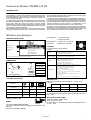
INSTRUCTIONS MANUAL
cb
Via Papa Giovanni XXIII, PERGOLA (PS)
S H A R K
3 1 0 S X
SHARK 310 AX/AXI
SHARK 310/MA
MODEL: SHARK 310
TYPE: SX (SEMIAUTOMATIC)
Note to the Readers
The infomation contained in this manual is subject to modifications without prior notice.
MEP S.P.A. CANNOT BE HELD LIABLE FOR EVENTUAL TECHNICAL ERRORS, PRINTING ERRORS OR OMISSIONS IN THIS
MANUAL NOR FOR ACCIDENTAL DAMAGES RESULTING FROM THE DELIVERY, PERFORMANCE AND USE OF THE PRESENT
MATERIAL.
Contents
Note to the Readers . . . . . . . . . . . . . . . . . . . . . . . . . . . . . . . 2
Contents . . . . . . . . . . . . . . . . . . . . . . . . . . . . . . . . . . . . . . . . . . . 2
Instructions manual SHARK 310 SX . . . . . . . . . . . . . . . 3
INTRODUCTION . . . . . . . . . . . . . . . . . . . . . . . . . . . . . . . . . . . . . 3
Machine’s specifications . . . . . . . . . . . . . . . . . . . . . . . . . . 3
CHAPTER 1
Machine’s functional components . . . . . . . . . . . . . . . . . 4
1.1
1.2
1.3
1.4
1.5
------
Head . . . . . . . . . . . . . . . . . . . . . . . . . . . . . . . . . . . . . . . . .
Vice . . . . . . . . . . . . . . . . . . . . . . . . . . . . . . . . . . . . . . . . . .
Hydropneumatic group . . . . . . . . . . . . . . . . . . . . . . . . .
Electropneumatic group . . . . . . . . . . . . . . . . . . . . . . . . .
Control panel . . . . . . . . . . . . . . . . . . . . . . . . . . . . . . . . . .
4
4
4
4
4
CHAPTER 2
Recommendations to the operator and
safety regulations . . . . . . . . . . . . . . . . . . . . . . . . . . . . . . . . . 5
2.1 -- Recommendations to the operator . . . . . . . . . . . . . . . .
2.2 -- Safety regulations . . . . . . . . . . . . . . . . . . . . . . . . . . . . . .
2.2.1 -- Protections against accidental blade
reach . . . . . . . . . . . . . . . . . . . . . . . . . . . . . . . . . . . . . .
2.2.2 -- Electrical components in compliance to
European Standard EN 60 204 first part 1984,
deriving from the pubblication IEC 204--1 1981 . .
2.2.3 -- Emergency devices in compliance to IEC 204--1
standard . . . . . . . . . . . . . . . . . . . . . . . . . . . . . . . . . . .
5
5
5
5
5
CHAPTER 3
Machine Installation . . . . . . . . . . . . . . . . . . . . . . . . . . . . . . . 6
3.1
3.2
3.3
3.4
3.5
------
Check list . . . . . . . . . . . . . . . . . . . . . . . . . . . . . . . . . . . . .
Minimum requirements . . . . . . . . . . . . . . . . . . . . . . . . .
Machine anchoring and handling . . . . . . . . . . . . . . . . .
Compressed air hook--up . . . . . . . . . . . . . . . . . . . . . . . .
Electric connection . . . . . . . . . . . . . . . . . . . . . . . . . . . . .
6
6
6
7
7
CHAPTER 4
Description machine cycles . . . . . . . . . . . . . . . . . . . . . . . 8
4.1 -- Description control panel . . . . . . . . . . . . . . . . . . . . . . . . 8
4.2 -- Manual cycle . . . . . . . . . . . . . . . . . . . . . . . . . . . . . . . . . . 9
4.3 -- Semiautomatic cycle . . . . . . . . . . . . . . . . . . . . . . . . . . . 9
CHAPTER 5
Diagrams, drawings and spares . . . . . . . . . . . . . . . . . . 10
5.1 -- Diagrams . . . . . . . . . . . . . . . . . . . . . . . . . . . . . . . . . . . .
5.1.1 -- Electric . . . . . . . . . . . . . . . . . . . . . . . . . . . . . . . . . . .
5.1.2 -- Pneumatic . . . . . . . . . . . . . . . . . . . . . . . . . . . . . . . . .
5.1.3 -- Hydraulic . . . . . . . . . . . . . . . . . . . . . . . . . . . . . . . . .
5.2 --Drawings . . . . . . . . . . . . . . . . . . . . . . . . . . . . . . . . . . . . .
5.2.1 -- Head group . . . . . . . . . . . . . . . . . . . . . . . . . . . . . . .
5.2.2 -- Vice group . . . . . . . . . . . . . . . . . . . . . . . . . . . . . . . .
5.2.3 -- Electropneumatic group . . . . . . . . . . . . . . . . . . . .
5.2.4 -- Spares . . . . . . . . . . . . . . . . . . . . . . . . . . . . . . . . . . .
10
10
10
10
12
12
13
14
15
CHAPTER 6
Adjustments . . . . . . . . . . . . . . . . . . . . . . . . . . . . . . . . . . . . . 20
6.1 -- Head stroke . . . . . . . . . . . . . . . . . . . . . . . . . . . . . . . . . . 20
6.2 -- Pneumatic circuit . . . . . . . . . . . . . . . . . . . . . . . . . . . . . 20
2
6.2.1 -- Head operating pressure . . . . . . . . . . . . . . . . . . .
6.2.2 -- Vice operating pressure . . . . . . . . . . . . . . . . . . . .
6.3 -- Hydraulic circuit . . . . . . . . . . . . . . . . . . . . . . . . . . . . . .
6.3.1 -- Refill oil compensation tank . . . . . . . . . . . . . . . . .
6.3.2 -- Band tensioning group . . . . . . . . . . . . . . . . . . . . .
6.4 -- Band guide system . . . . . . . . . . . . . . . . . . . . . . . . . . .
6.4.1 -- Band guide head . . . . . . . . . . . . . . . . . . . . . . . . . . .
6.4.2 -- Band guide carbide tips inserts . . . . . . . . . . . . . .
6.4.3 -- Band holder buttons . . . . . . . . . . . . . . . . . . . . . . . .
6.4.4 -- Front flywheel . . . . . . . . . . . . . . . . . . . . . . . . . . . . . .
6.4.5 -- Rear flywheel . . . . . . . . . . . . . . . . . . . . . . . . . . . . .
6.5 -- Band . . . . . . . . . . . . . . . . . . . . . . . . . . . . . . . . . . . . . . . .
6.5.1 -- Perpendicularity between
band and working surface . . . . . . . . . . . . . . . . . .
6.5.2 -- Orthogonality between band and
material backstop . . . . . . . . . . . . . . . . . . . . . . . . . .
20
20
21
21
21
22
22
22
22
22
22
22
22
23
CHAPTER 7
Cutting speed . . . . . . . . . . . . . . . . . . . . . . . . . . . . . . . . . . . . 24
7.1 -- Machine (standard version) . . . . . . . . . . . . . . . . . . . . 24
7.2 -- Machine (w/inverter) . . . . . . . . . . . . . . . . . . . . . . . . . . 24
CHAPTER 8
Maintenance and choice of consumption
materials . . . . . . . . . . . . . . . . . . . . . . . . . . . . . . . . . . . . . . . . 24
8.1 -- General machine maintenance . . . . . . . . . . . . . . . . . .
8.1.1 -- Daily . . . . . . . . . . . . . . . . . . . . . . . . . . . . . . . . . . . . .
8.1.2 -- Weekly . . . . . . . . . . . . . . . . . . . . . . . . . . . . . . . . . . .
8.1.3 -- Monthly . . . . . . . . . . . . . . . . . . . . . . . . . . . . . . . . . .
8.2 -- Maintenance operating systems . . . . . . . . . . . . . . . . .
8.2.1 -- Drive box . . . . . . . . . . . . . . . . . . . . . . . . . . . . . . . . .
8.3 -- Consumption materials . . . . . . . . . . . . . . . . . . . . . . . . .
8.3.1 -- Oils for hydraulic/pneumatic circuit . . . . . . . . . . .
8.3.2 -- Oils for drive box . . . . . . . . . . . . . . . . . . . . . . . . . .
8.3.3 -- Oils for lubro--refrigerating fluid . . . . . . . . . . . . . .
24
24
24
25
25
25
25
25
25
25
CHAPTER 9
Material Classification . . . . . . . . . . . . . . . . . . . . . . . . . . . 26
9.1 -- Band choice . . . . . . . . . . . . . . . . . . . . . . . . . . . . . . . . .
9.1.1 --Tooth pitch . . . . . . . . . . . . . . . . . . . . . . . . . . . . . . . .
9.1.2 -- Feed and cutting speed . . . . . . . . . . . . . . . . . . . . .
9.1.3 -- Lubro--refrigerating fluid . . . . . . . . . . . . . . . . . . . . .
9.1.4 -- Band structure . . . . . . . . . . . . . . . . . . . . . . . . . . . . .
9.1.5 -- Band types . . . . . . . . . . . . . . . . . . . . . . . . . . . . . . . .
9.1.6 -- Band choice table according to cutting
speed and feed . . . . . . . . . . . . . . . . . . . . . . . . . . . .
9.2 --Steels classification . . . . . . . . . . . . . . . . . . . . . . . . . . .
9.2.1 -- Steels nomenclature table . . . . . . . . . . . . . . . . . .
26
26
26
26
26
27
28
29
29
CHAPTER 10
Diagnosis table . . . . . . . . . . . . . . . . . . . . . . . . . . . . . . . . . . 30
10.1 -- Diagnosis for bands and cuts . . . . . . . . . . . . . . . . . 30
10.2 -- Troubleshooting . . . . . . . . . . . . . . . . . . . . . . . . . . . . . . 34
CHAPTER 11
Machine noise level . . . . . . . . . . . . . . . . . . . . . . . . . . . . . . 37
11.1 -- Machine noise level survey . . . . . . . . . . . . . . . . . . . 37
11.2 -- Noise level values . . . . . . . . . . . . . . . . . . . . . . . . . . . 37
Shark 310 sx
Instructions Manual SHARK 310 SX
INTRODUCTION
In respect to the modern production technologies, all the more efficient, MEP S.p.A. presents the SHARK 310SX new version which
has been designed so as to respond in a simple and reliable way
to the wide range of cutting requirements which exist in each and
every modern workshop.
The high cutting capacities both for single stocks or bundles, together with the possibility of mitre cutting 45 degrees left up to 45 degrees right, make this model very adapt to assolve cutting
requirements in workshops and turning shops, in steelwork shops
which cut beams and in mechanical workshops which may have
the strangest cutting requirements.
This model functions by means of a microprocessor and is structurally rigid, noiseless and safe to use; it cuts with minimum wastage
(1.2mm) and great applicable flexibility, different types of materials
such as stainless steel, light alloys, aluminium, bronze and copper
with a high speed level and precision.
Furthermore a HEAD POSITIONING SYSTEM has been introduced. This gives you the possibility of positioning the head directly
from the control panel eliminating the limit switches and manual
head stroke adjustment. This innovation allows you to control the
operative functions in act by means of a visualizzation of the
machine’s functional systems directly on the control panel.
We thank you for having chosen our product and trust you shall use
this machine to your full satisfaction for a long time bearing in mind
also the recommendations stated in this manual for a correct use
of the machine and a minimum but constant maintenance.
Machine specifications
IDENTIFICATION PLATE:
Model and Type
000001
Serial number
Address of the
1ª Speed 36 mt/min.
2ª Speed 72 mt/min.
Cutting speed:
(w/inverter)
1ª Speed 20 -- 45 mt/min.
2ªSpeed 35-- 90 mt/min.
OPTIONAL
AB C
Inverter: electronic speed variator
Features:
OFFICINA MECCANICA di MARIO ROSSI s.n.c.
Via Enrico Toti nr.1
dealer
Cutting speed:
61045 PERGOLA (PS)
Power
-- Power of the most potent motor Kw 2,2
- Maximum sinusoidal power output 65Amp
-- Maximum output power KVA 4,22
Current supply
-- Feeding tension: three--phase 3 x 380 V (plus/minus 10%)
-- Feeding frequency: 50/60 Hz (plus/minus 5%)
Output
-- Wave shape: sinusoidal
-- Output tension: three--phase from 0 to 380 V
-- Output frequency: from 2,5 to 100 Hz
-- Frequency stability: plus/minus 1%
Telefono 0721/737737
* N.B. : to mention when requiring servicing on the machine
DIMENSIONS:
-- Performance: 88% at the maximum power
a = 2.000 mm.
- Protected from mechanical overpower (limited power supply)
-- Protected from short--circuit phase--to--phase
- Not protected from short--circuit phase--earth
- Protected from overheating
- Protected from rigenerative load overtvoltage
b = 1.900 mm.
c = 970 mm.
d = 1.020 mm.
Protections
- Protected from overvoltage caused by power boosts which last
less than 1 millisecond
weight= Kg 500
-- Protected against unsufficient power supply or microinterruptions of power
- Protected fron short circuit between potentiometer terminals
CUTTING CAPACITIES:
MAIN MOTOR:
Main motor: asynchronous three--phase 2 -- 4 poles; 50 Hz.
Features:
Section
Tension Volt
Amp absorb.
Power Kw
Rev/min.
0 degrees
250
230
310x230
2 poles
380
4,4
1,8
2.855
45 degrees left
220
210
210x210
4 poles
380
5,7
1,5
1.415
45 degrees right
220
210
210x210
100
100
100x100
60 degrees left optional
Class of protection IP 54.
In conformance to CEI standards relative to pubblication IEC 34 dd
July 1,1985
MOTOR ELECTRIC PUMP:
Maximum vice opening: 315 mm.
Working pressure: 6 Bar.
BAND:
Dimensions: 2.835 x 25,4 x 0,9 mm.
You may use bands which have a length in between 2820mm and
2850mm.
SINGLE--PHASE 1 SPEED 50HZ
Class of protection IP 55.
In conformance to CEI Standards relative to pubblication IEC 34
dd July 1,1985.
Band tension: 50 Bar = 800 Kg.
Shark 310 sx
3
Functional parts of the machine
So as to understand better the function of the machine, which will
be thoroughly illustrated in the chapter ”Description of machine
Cycles”, we wish to point out the various parts which compose it
and where these are located.
1.1 -- Head
The head is the part which carries out the cut ,made out of cast
iron ,on which the following components are mounted: the band
(see 6.5) the parts which guide the band itself (see 6.4) the band
tension, the drive box and the main motor.The movements of the
head are given by the pivot point on the cutting plane which has
a vertical stroke (top to bottom) programmable on the control panel. This part is manually operated by means of the handle during
the manual cycle or by means of an oleopneumatic cylinder during the semiautomatic cycle.
1.4 -- Electropneumatic group
The panel illustrated below is the electropneumatic group.This
consists in the air treatment group, an electrovalve at 3 outlets
and two electrovalves at 5 outlets together with the relative coils.
1.2 -- Vice
The vice is the component which holds the material during the
cut; it consists in a vice support called ” nut”, which is fixed on the
working table and a vice screw integral with a slide on which the
movable jaw is mounted.The vice is operated manually by means
of the relative handwheel or by the air vice cylinder which is actioned by means of an electro--pneumatic group.
1.5 -- Control panel
The control panel designed in heavy sheetmetal is safe and easy
to reach: easy because just by taking off a few screws you can
uncover the panel completely; safe because the main power
switch, situated on the right handside of the panel grants maximum safety to the operator. the panel is ealized with silk--screen
process on glossy scratch--resistant support.
1.3 -- Hydropneumatic group
This group actions the head and consists in an air--oil cylinder, a
hydraulic brake and regenerating electrovalves.By means of the
head downstroke regulator, located on the control panel, you can
adjust the quantity of oil which flows through the cylinder and naturally also the head downstroke speed.
4
Shark 310 sx
Recommendations to the operator and safety regulations
At this point, after having had a summarized view of the model
SHARK 310 SX, please carefully read this chapter , full of useful
information for the correct use of the machine, before you start
using it. This will avoid any inattentions which could jepordaze the
correct function of the machine.Furthermore you will find listed in
this chapter the European standards according to which this product has been manufactured. We trust you will treasure what you
are about to read and wish you GOOD WORK!
2.2 -- Accident Prevention Standards
Besides being a guide for the correct use of the machine, this instructions manual is intended to be an instrument finalized to protect machine operators against hazards due to an unappropriate
use of the machine.Hereunder are listed the standards relative to
Machine Tools Instructions (DPR April 27,1955, N.547) a document which includes a complex system of standards concerning
health and phisical integrity of workers; these standards have been applied to the model Shark 310 SX.
2.2.1 -- Protections against accidental contact
with the band
2.1 -- Recommendations to the operator
Always wear adequate eye protection;
Do not use machine if all protections aren’t correctly in place;
Don’t reach in with hands or arms in cutting area while machine
is in function;
Don’t move machine while it’s cutting;
Don’t wear baggy clothes, long sleeves, big gloves, bracelets,
chains or any other object which could get hooked on the machine while it’s in function; keep long hair tied up;
Before starting to cut, support adequately material at both ends;
Disconnect plug from power socket before carrying out any
maintenance or repair on the machine;
Cutting area has to be always kept clean from tools or objects;
Before starting to cut, check that the material is securely clamped in the vice and that the machine is correctly set. The following
are a few correct examples of how different types of materials are
clamped on convential sawing machines;
Yellow metal guard fixed by screws on the rear bandguide
head;
Yellow metal guard fixed by screws on the front bandguide
head; a whole with the bandguide head so as to grant maximum
coverage of the band when the bandguide head is brought forward towards the material which has to be cut, leaving free only
the part which is cutting;
Device to bring the band close to the material which is to be cut:
the machine has a ”head positioning system” so as to move mechanically the band just above the material and those avoid
”dead times”;
Green cover to protect band and bandguide head when it is positioned at its maximum opening;
vice actioned by air with a maximum stroke of 8mm in compliance to the current standards concerning pneumatic on/off devices.
2.2.2 -- Electricals according to European Standard EN 60 204 first part 1984 from pubblication IEC 204--1 1981
So as to reach inside the electric panel you need to remove the
relative screws and the main switch cover;
Control tension on actuators 24v. A.C. in compliance to Chapter
6 of the European Standards concerning ” Control and signal circuits” second paragraph ”Control Circuits” first subparagraph
”Preferential tension values for control circuits”;
Electric circuit protected against short--circuits by means of fuses and all parts touched while operating the machine, or accidentally, are earthed;
Protection, by means of a minimum tension coil, that the machines restarts after a downfall in power.
Do not use the machine to cut dimensions beyond those indicated as the maximum machine capacities;
Don’t use bi--metal bands which have lengths different from those indicated on the machine specifications;
When cutting very short pieces be careful that they aren’t dragged behind the material backstop otherwise they would jam the
band;
When you’re using the hydraulic vice in automatic, be sure that
it reaches to clamp the material (because it has a stroke of only
8mm) and that the clamping pressure is correct;
Don’t do more than one thing at a time and don’t hold more
things at a time in your hands. Keep you hands as clean as possible.
Attention: if the band should get jammed in the material, press
immediately the red emergency button and then proceed to rest
the machine. If the band does not free itself, stop the machine and
open slowly the vice so as to remove the material. Check that the
band nor its teeth have broken in which case you need to put a
new band on.
Before carrying out any repair on the machine, consult a qualified MEP technician first.
2.2.3 -- Emergencies in compliance to Standard
IEC 204--1
In compliance to the following standards:
Chapter 5 Paragraph 6 Subparagraph 1 ”Emergency stop
devices ”:
«the emergency stop device stops immediately all the dangerous
and non--dangerous functions of the machine»
Chapter 6 Paragraph 2 Subparagraph 4 Point 7 ”Protection covers ”:
«the removal of protective covers which are to avoid the access
to dangerous parts or areas immediately stop the machine; the
machine must not restart again by just putting the m back in place
but the machine has to be specifically reactivated»
Chapter 6 Paragaph 2 Subparagraph 6 Point 2 ”Automatic
stop at the end of the cycle or when the material is finished”:
«The machine automatically stops at the end of the cycle or when
the material is finished, without having the operator to intervene.
Shark 310 sx
5
Recommendations to the operator and safety regulations
All control actuators have to be reactivated so as to start a new
cycle»
Chapter 6 Paragaph 2 Subparagraph 7 ”Emergency
stops”:
«each time an emergency stop intervenes during an automatic or
semiautomatic cycle it is possible to complete cycle in course and
bring machine back to startying position.»
...emergencies applicated to SHARK 310 SX:
Emergency stop: on the control panel of the machine there is
a emergency push--button which remains hooked; it has a red
”mushroom” top and yellow base. To release this push--button it
is necessary to rotate actuator of 45 degrees. After having released this emergency the machine must be reset.
Contact pressure for band tension: the machine immediately stops in case of band breakage or a downfall in pressure.
Band protection cover: in case band cover is opened even
if accidentally, while the machine is executing its cycle, a microswitch is actioned which immediately stops all the functions of the machine.
Machine installation
OPTIONALS
ACCESSORIES UPON REQUEST:
-- spindle speed 18/36 mt/min.;
-- electronic speed variator (inverter) mt/min 20--45/35--90;
-- supplementary jaw so as to cut at 60 degrees (max capacity 100
x 100);
-- bi--metal band 2835x0,9x25mm;
-- loading table (componable module 1500mm);
-- adapter for unloading table;
-- unloading table 1500mm;
-- unloading table 3000mm;
-- unloading table 4500mm;
-- unloading table 6000mm;
-- emulsible oil Kg. 5;
3.2 -- Minimum requirements
The steel base of the macchine is fixed to the foundations of the
workshop by means of two set screws which are on the side of
the steel base , towards the inside. These set screws are screwed
onto a nut which has been previously cemented to the floor and
tightened on top by another nut. When positioning the machine
one has to keep in due consideration the overall dimensions
which are indicated on the machine specifications.
REAR
15 mm.
STEEL BASE
FRONT
700 mm.
In case the machine needs to be moved from its original location,
if it has a pallet, use a forklift; if the machine is set to the floor use
a belt to hook the platform as illustrated on the following photos:
Pass the belt under the
plateform, on the backside
of the head pivoting point.
The belt will have to come
out from under the plateform on the lefthand side of
the vice in front of the machine.
The minimum requirements which a workshop has to have for a
correct functioning of the machine are:
-- network/frequency tension:see values on motor plate
--working pressure: doesn’t have to be below 6 BAR nor above
9 BAR
--room temperature: from --10 to +50 C
-- humidity: not above 90 %
ATTENTION !
The machine is already protected against possible overvoltages
in the workshop.
6
740 mm.
Before starting to install the machine, check all the standard and/
or optional accessories which came along with the machine.The
standard sawing machine SHARK 310 SX 2 SPEEDS is supplied
complete with:
-- operating system for manual function;
-- steel base with wide tray to collect swarf and pull out coolant
tank;
-- hydraulic transducer to read band tensioning;
-- electric pump to lubricate band;
-- bi--metal band 2835x0,9x25mm for solids/sections;
-- Low voltage safety device(Volt 24) with MINIMUM TENSION
COIL, EMERGENCY and MOTOR THERMAL RELAY;
-- wire chip brush;
-- machine is predisposed to be equipped with loading tables;
-- tool kit;
The tool kit is put inside the machine before being packed and includes:
-- hex.wrench mm. 4;
-- hex wrench mm. 10;
-- cut to measure stop diam.20mm complete w/fork and trip lever
diam.8mm + set screw 8x35mm;
-- stock support arm;
-- this instructions manual;
3.3 -- Anchoring and moving machine
around
370 mm.
3.1 -- Check list
Shark 310 sx
Machine installation
Hook the two ends of the
belt to the hook of the crane and pull up.
3 --Turn the main power switch to 1 (the led RUN on the Head Positioning System will remain on);
5 -- Make sure that the rotation of the motor is correct. So as to
check this you need to carry out the following steps:
a) tension band to 50 BAR
3.4 -- Connection to compressed air
This model is supplied complete with an air treatment group; in
any case so as to avoid any possible damage to the system and
obtain an optimal functioning in time, we would suggest to hook
the machine to a feeding system which has features as illustrated
below. Bear in mind that the SHARK 310 SX has an air consumption of 7.3 NI per complete cycle.
b) be sure the cover n.1036 is properly closed, otherwise if the
safety limit switch n.1023 which is inside the cover, isn’t correctly
pressed, the machine will be in emergency and therefore shall not
operate.
c) check that the machine isn’t in emergency (the red button
n.1605 has to be released).
Caption
1
2
3
4
5
6
-------
tube
condensate collector
drainage tap
air filter
drainage tap
connection tube
1
d) set machine to manual cycle by positioning selector n.1604 as
below:
4
2
3
6
5
e) select cutting speed to means of the pole change switch
n.1614.
3.5 -- Connection to power
So as to connect the machine to the electric netwrok, you must
carry out the following steps:
1 -- connect machine cable to a proper ”plug” according to the
socket you have decided to use.
f) action the jog which is on the head control lever n.1124
CONNECTION FOR SYSTEMS WITH NEUTRAL ”5 WIRES”
R = L1
S = L2
T = L3
PE = GND
N =NEUTAL
g) at this point, if all the steps have been carried out correctly, the
motor will start and the band will start running.
CONNECTION FOR SYSTEMS NEUTRAL ”4 WIRES”
R = L1
S = L2
T = L3
PE = GND
ATTENTION!
In systems with neutral, it’s very important to be careful when connecting the sky blue wire of the neutral because if it’s connected
to a phase, this will bring tension to those parts which are instead
connected for neutral--phase tension.
2 -- Connect plug to socket, assuring yourselves first that the tension in the workshop is that for which the machine is predisposed.
VOLT ?
VOLT ?
Make sure the band is rotating in the correct direction, as indicated in figure.If not all you have to do is invert two wires
of the phase on machine power input.
Now the machine is ready to be used for the work it has been designed for. The functioning cycles are thoroughly illustrated in
Chapter 4.
Shark 310 sx
7
Description of machine cycles
In this chapter we shall analize all the functions of the machine,
which describ step by step all the operations of the machine. We
shall therefore start by describing the various push--buttons and
components of the control panel.
RUN
ELECTRONIC
START
MEM
4.1 -- Description control panel
You can see illustrated hereunder the components which are on
the control panel of the SHARK 310SX;to each arrow and number
corresponds the description available on the following pages.
1
2
3
4
5
10
2 -- RED EMERGENCY BUTTON
6
9
8
By pressing this button all the functions of the machine are interrupted immediately:
-- the band motor shuts off;
-- the head and vice cylinders rest locked;
The emergency isn’t only software but also hardware because
feeding to all motor contactors is interrupted.
7
MAGNETOTHERMAL MAIN SWITCH
3 -- COOLANT SELECTOR
The machine is equipped on the righthand side of the panel,with
a main switch that, if positioned on 1, brings power to the machine
by means of the MINIMUM TENSION COIL and the MAGNETOTHERMAL BAND MOTOR RESET.
This device has three protection systems against voltage downfalls. In case there is a downfall in power, it releases all electric
devices, stopping the machine immediately and avoids that it can
start up again automatically when power comes back on. Another
function is that to reset the thermal relay which protects the machine from over--voltages. When the machine is on the led RUN
of the Head Positioning System is on.
1 -- HEAD POSITIONING SYSTEM
HEAD POSITIONING SYSTEM
The MEP 11 controller has been called ”HEAD POSITIONING
SYSTEM” because it also has the possibility of memorizing the
position of start cycle and end cycle, without the need of limit switches, directly on the control panel.Besides this it helps out in the
diagnosis of machine functions since you can visualize on the
control panel the various machine functions.
8
This selector has three positions so as to exclude the coolant, forr
cutting non--ferrous materials and/or synthetics. Furthermore,
when positioned on pistol you can use the coolant to clean machine surface.
4 -- SELECTOR MANUAL/SEMIAUTOMATIC
When positioned on MANUAL it allows you to use the machine
as follows:
-- open/close the vice by means of push--button or foot--pedal;
-- activates manual control of motor;
-- opens regenerating electrovalve so that tghe head can descend manually.
When positioned on SEMIAUTOMATIC it allows you to:
-- open/close the vice;
-- operate foot--pedal to start cycle;
-- carrys out the cut within the two positions memorized on the
head positioning system.
Shark 310 sx
Description of the machine cycles
5 -- POLE CHANGE SWITCH
-- FOOT--PEDAL
Selects band cutting speed, on the standard 2 speed version, at
36 or 72 mt/min.
In SEMIAUTOMATIC it starts cutting cycle:
-- vice closes;
-- band motor starts;
-- head descends to cut;
In MANUAL it is abilitated to copen/close vice, in parallel with the
relative push--button.
OPTIONAL
Selecta the band speed cutting range: from 20 to 45 mt/min at the
first speed and from 35 to 90 mt/min at the second speed; this is
possible on the machines equipped with the electronic speed variator (INVERTER).
-- JOG HEAD CONTROL LEVER
6 -- PUSH--BUTTON TO OPEN/CLOSE VICE
Thia push--button allows you to open and/or close the vice so as
to clamp properly the material you need to cut and/or to release
them after having cut in MANUAL cycle. The conditions necessary to activate this push--buttton are:
SEMIAUTOMATIC cycle
-- no emergency present;
-- head in resting position (led on HPS on);
MANUAL cycle
-- no emergency present;
(after each emergency returrn head to its resting position).
7 -- HEAD DOWNSTROKE REGULATOR
Used to regualtye head feeding speed, in other words the downstroke speed of the head, so as to optimize cutting conditions.
8 -- VICE PRESSURE REGULATOR
On the control lever to operate the machine manually, there is a
jog which activates the band motor. This push--button is activated
when the machine is used in MANUAL cycle and if no emergency
is present.
4.2 -- Manual cycle
This cycle allows you an immediate use of the machinees, such
as a traditional saw. Infact by placing the selector on MANUAL
you can carry out the following:
1) the jog on the head control lever is activated to run motor;
2) the automatic function f the vice remains and furthermore
you can control vice opening/closure both by foot--pedal
and/or push--button.
3) the head can be operated freely; it isn’t necessary to open
head downstroke regulator because the particular MEP
system, by means of the regenerating valve, does not require and modification of the SEMIAUTOMATIC function
parameters.
4.3 -- Semiautomatic cycle
Used to regulate clamping pressure of the material which is being
cut; It remains aligned when thee vice is closed both when using
the machine in SEMIAUTOMATIC or MANUAL cycle.
9 -- VICE PRESSURE MANOMETER
Indicates vice clamping pressure and its value can be read at any
time, both when the machine is cutting or not.
10 -- DIGITAL AMPERMETER
It is constantly aligned to the band motor and indicates correct
motor absorbment, giving you thus the possibility of checking
band wear.
So as to carry out this cycle you need to:
1) press red emergency button;
2) position the selector MAN/SEMIAUT on SEMIAUTOMATIC;
3) release emergency;
4) position the material you need to cut perpendicular to the
band:
on the HPS, bring band close to
5) by means of the key
the material to cut and then memorize start cut position
with the key
;
on the
6) position head at end cut by means of the key
HPS and memorize with key
(the head will return to top
position);
7) close head downstroke regulator;
8) adjust manually vice opening at approx.ly 4mm from the
material:
9) select cuttting speed: 1ª or 2ª speed;
10) press foot--pedal to start cycle.
Once having started the cycle, the machine will:
a) close vice if it is open;
b) start band motor;
c) bow unit will descend to cut (speed chosen by means of the
regulator);
d) at the end of the cut the head will return to top position;
e) vice will open again.
Shark 310 sx
9
Diagrams, knocked-- down drawing and spare parts
In this chapter are the functional diagrams of the machine and he
knocked--down drawings. This documentation will give you the
possibility to find out exactly where each component is fitted
when having to repair or carry out maintenance on the machine,
after having spoken first with a MEP technician. Furthermore, this
documentation will give you the possibility of ordering the correct
spare partss you should require, by indicating the relative position number on drawing.
5.1.2 -- Hydraulic
CAPTION HYDRAULIC COMPONENTS
Electrovalve coil
Regolatore velocità discesa testa
EVR -- Cylinder regenerating valve
EVB -- Cylinder locking valve
Head control air/oil cylinder
Oil compensation tank
5.1 -- Diagrams
5.1.1 -- Pneumatic
Vice pressure regulator
Electrovalve coil
EVM -- Vice cylinder valve
EA -- air input valve
EVT -- Head cylinder valve
Head control air/oil cylinder
Vice cylinder
EVB
EVR
OLIO
Air treatment group
ARIA
CAPTION PNEUMATIC COMPONENTS
5.1.3 -- Electric
Manometer
CAPTION ELECTRIC COMPONENTS
EVT
ARIA
EA
Compressed
air
input
Push--button
Selector
Emergency
Microswitch
Limit switch
Pressure switch
Transfomer
Magnetothermal
Fuse 24 Volts
Manometer
on panel
Relay
Contactor
Ampermeter
Footpedal
Electric pump
Filter RC
Motor
Electrovalve
Potentiometer
OLIO
EVM
Pole change switch
10
Shark 310 sx
MEP 11 controller
1398
1509
M (AR)
A (G)
1510
1511
1385
1500
1512
1508
1513
1501
1502
1503
1514
1504
Shark 310 sx
1240
1023
1128
1241
1120
1030
1515
1507
1506
1516
1505
1517
1518
Diagrams, knocked--down drawing and spare parts
11
Diagrams, knocked--down drawing and spare parts
5.2 -- Knocked--down drawings
Hereunder are the various parts which compose the machine to give you a better knowledge of your own machine.
5.2.1 -- Head group
12
Shark 310 sx
Diagrams, knocked--down drawing and spare parts
5.2.2 -- Vice group
Shark 310 sx
13
Diagrams, knocked--down drawing and spare parts
5.2.3 -- Electropneumatic group
14
Shark 310 sx
Diagrams, knocked--down drawing and spare parts
5.2.4 -- Spare parts
Position
Codes
of
groups
1000
1001
1002
1003
1004
1005
1006
1007
1009
1010
1017
1018
1019
1020
1021
1022
1023
1024
1025
1026
1027
1028
1029
1030
1031
1032
1033
1034
1035
1036
1037
1038
1039
1040
1041
1042
1043
1047
1048
1052
1053
1054
1055
1056
1057
1058
1059
1060
1061
Code
043.0014
043.0562
043.5610
043.5615
090.0125
090.0265
090.0271
090.0621
090.0631
090.1100
007.3861
043.0260
043.0556
043.0250
043.0250
043.0229
001.4302
010.1201
001.4019
025.0069
010.1201
010.1201
010.1201
010.1201
007.3616
010.1201
022.0502
007.3803
010.1201
010.2301
010.1201
010.1801
034.0902
019.1706
010.1201
025.0201
025.0625
001.4011
010.1201
016.0912
025.0113
025.0067
010.0352
025.0074
010.1201
025.0627
010.1201
010.1201
016.0262
034.0206
007.3825
007.3811
010.0915
007.3869
025.0236
010.1201
025.0235
001.4018
010.1201
Description
GR.OLEOPNEUM.MM.150 1203-4/1232-46
FRC104D00+LC104L00 1215-18/1223-27
SERIE GUARNIZ.CILINRO VOLAMPRESS
SERIE GUARNIZIONI CILINDRO IDROPN.
GRUPPO MORSA POS. 1300-23/1387-94
IMPUGNATURA COMPLETA POS. 1118-1126
IMPUGNATURA TIPO MEP POS. 1118-1125
GRUPPO TENS.LAMA 1000-05/1128/52-59
DISPOSITIVO PULILAMA POS. 1072-1076
ASTA BATTUTA TAGLI A MIS. 1361-1370
CILINDRO TENSIONAMENTO
TAPPO TTE4 1/4 - CL 2611
MANOMETRO DIAM.50 0-60
GOMITO M.F. 1/4 CL 2020
GOMITO M.F. 1/4 CL 2020
RIDUZIONE MF 1/4 - CL 2520
ARCHETTO
VITE TCEI 8 X 25
VOLANO LIBERO
CUSCINETTO 32007X
VITE TE 8 X 20
RONDELLA DIAM. 8
VITE TE 8 X 20
VITE TCEI 8 X 20
GHIERA FIX CUSCINETTI
VITE TCEI 6 X 12
FINECORSA OMRON D4MC-5000
PIASTRINO FIX F.C.COPERC.ARCHETTO
VITE TCEI 6 X 20
DISTRIBUTORE LIQUIDO REFRIGERANTE
VITE TCEI 4 X 8
CHIUSURA LEVA ”D” ZINCATA
TAPPO OLIO SFP 1/2” ROSSO
HP 2/2,5 2/4P VOLTS................
CHIAVETTA 8 X 7 X 40
ANELLO TENUTA 25X42X7
GUARNIZIONE MOTORE
COPERCHIO PORTA MOTORE
VITE TCEI 5 X 12
COPERCHIO ARCHETTO
VITE SENZA FINE DIS. 468
CUSCINETTO 3207
GHIERA AUTOBLOCCANTE 35 X 1,5
CUSCINETTO 6003
ANELLO SEEGER DIAM. 17
GUARNIZIONE COPERCHIO PORTA MOTORE
ANELLO SEEGER DIAM. 45
VITE BUTON 5 X 10
PROTEZIONE LAMA POSTERIORE
VOLANTINO TENSIONAMENTO LAMA
PERNO REGISTRO TENSIONAMENTO LAMA
DISTANZIALE VOLANTINO
MOLLA A TAZZA 50 X 18,4 X 3
PISTONE TENSIONAMENTO LAMA
ANELLO DI TENUTA NI 150 45-55-7
SPINA ELASTICA 6 X 35
ANELLO TENUTA NI 150 18-25-4,5
SLITTA TENDILAMA MOD. 1212
VITE VCE P.CILINDR. 6 X 16
Shark 310 sx
U.M.
NR
NR
NR
NR
NR
NR
NR
NR
NR
NR
NR
NR
NR
NR
NR
NR
NR
NR
NR
NR
NR
NR
NR
NR
NR
NR
NR
NR
NR
NR
NR
NR
NR
NR
NR
NR
NR
NR
NR
NR
NR
NR
NR
NR
NR
NR
NR
NR
NR
NR
NR
NR
NR
NR
NR
NR
NR
NR
NR
Q.ty
1
1
1
1
1
1
1
1
1
1
1
1
1
1
1
1
1
4
1
2
4
4
4
4
1
2
1
1
1
1
2
1
1
1
1
1
1
1
4
1
1
1
1
1
1
1
1
2
1
1
1
1
6
1
1
1
2
1
1
15
Diagrams, knocked--down drawing and spare parts
Position
1062
1064
1065
1066
1067
1068
1069
1070
1071
1072
1073
1074
1075
1076
1077
1078
1079
1080
1081
1082
1083
1084
1085
1086
1087
1088
1089
1090
1091
1092
1093
1094
1095
1096
1097
1098
1099
1100
1101
1103
1104
1105
1106
1107
1108
1109
1110
1111
1114
1115
1116
1117
1118
1119
1120
1121
1122
1123
1124
1125
1126
1127
1128
16
Code
010.1201
010.1201
016.0261
001.4022
010.1721
010.1201
010.1201
016.0024
028.0360
010.1201
010.0921
010.2201
025.0552
025.0803
028.0130
043.0652
001.4023
010.1702
007.3871
001.4013
010.1201
034.1003
010.1201
010.1201
010.1201
010.1201
010.1701
010.1703
010.1201
010.1201
007.3828
007.3872
010.1201
034.0900
001.4010
025.0626
025.0057
010.0352
025.0114
007.3616
025.0067
010.1201
007.3822
034.0905
025.0200
007.3842
010.1201
001.4024
010.1201
007.3843
025.0272
010.0352
025.0691
010.1201
022.0515
010.0928
034.1221
010.1201
010.1201
022.0157
010.1909
034.1110
043.0142
Description
VITE TE 6 X 25
SPINA ELASTICA 6 X 20
PROTEZIONE LAMA ANTERIORE
TESTINA GUIDALAMA ANTERIORE
PREMILAMA SHARK
VITE TCEI 8 X 16
VITE TCEI 4 X 12
PIASTRINO PORTA PULILAMA
GOMMINO PULILAMA
VITE TE 6 X 25
MOLLA X PULILAMA
PORTASPAZZOLA PULILAMA
SPAZZOLA PULILAMA DIAM. 50
BOCCOLA GRAFITATA L. 10 DIAM. 6
RACCORDO 1/4-9 CL 2601
RUBINETTO 1/4 F.M.
TESTINA GUIDALAMA POSTERIORE
GUIDALAMA 2 INSERTI POSTERIORE
SUPPORTO TESTINA ANTERIORE
STAFFA BLOCCAGGIO TESTA
RONDELLA DIAM. 12
LEVA A SCATTO 12 MA + GRANO 12 X 70
VITE VCE P. PIANA 6 X 12
VITE TCEI 8 X 20
VITE TCEI 8 X 16
VITE VCE P.PIANA 6 X 12
GUIDALAMA 1 INSERTO
GUIDALAMA A 2 INSERTI ANTERIORE
VITE TCEI 12 X 60
VITE TCEI 12 X 35
BOCCOLA BATTUTA FINE CORSA
SUPPORTO TESTINA POSTERIORE
VITE TCEI 8 X 16
TAPPO LIVELLO OLIO SLNT 38 3/8
COPERCHIO RIDUTTORE
GUARNIZIONE COPERCHIO RIDUTTORE
CUSCINETTO 62.06
GHIERA AUTOBLOCCANTE 35 X 1,5
CORONA ELICOIDALE DIS.468
GHIERA FIX CUSCINETTI
CUSCINETTO 3207
VITE TCEI 8 X 20
PERNO SUPPORTO SNODO TESTA
TAPPO OLIO TAO/3 1/2” NERO
ANELLO TENUTA 62 X 45 X 10
ALBERO MOTORE
VITERIA E BULLONERIA
VOLANO MOTORE SHARK + CALETTATORE
VITE VCE P. PIANA 8 X 16
ALBERO VOLANO LIBERO
ANELLO DI PROTEZIONE NILOS 32007
GHIERA AUTOBLOCCANTE 35 X 1,5
SERIE GUARNIZIONI X IMPUGNATURA
VITE AUTOFIL. 6 X 15
MICROINTERRUTTORE V-213-1C6
MOLLA X IMPUGNATURA MEP DIS.1189559
IMPUGNATURA DIS. MEP
SPINA TEMP. RETT. 5 X 25
VITE VCE P. CIL. 6 X 25
CAVO 2 X 1,5
LEVA COMANDO T.BT/NOT-AUS
VOLANTINO DIAM.30 M6 X 9
PRESSOSTATO OLIO
Shark 310 sx
U.M.
NR
NR
NR
NR
NR
NR
NR
NR
NR
NR
NR
NR
NR
NR
NR
NR
NR
NR
NR
NR
NR
NR
NR
NR
NR
NR
NR
NR
NR
NR
NR
NR
NR
NR
NR
NR
NR
NR
NR
NR
NR
NR
NR
NR
NR
NR
NR
NR
NR
NR
NR
NR
NR
NR
NR
NR
NR
NR
NR
MT
NR
NR
NR
Q.ty
1
1
1
1
2
2
1
1
1
1
1
1
1
2
2
2
1
1
1
1
1
1
8
4
2
2
2
1
1
1
1
1
4
1
1
1
1
1
1
1
1
4
1
1
1
1
2
1
1
1
2
1
1
3
1
1
1
1
1
1.4
1
2
1
Diagrams, knocked--down drawing and spare parts
Position
1129
1130
1131
1132
1133
1200
1201
1202
1203
1204
1205
1206
1207
1208
1209
1210
1211
1212
1213
1214
1215
1216
1217
1218
1219
1220
1221
1222
1223
1224
1225
1226
1227
1228
1229
1230
1231
1232
1233
1234
1235
1236
1237
1238
1239
1240
1241
1242
1243
1245
1246
1247
1248
1249
1250
1251
1252
1253
1254
1255
1256
1300
1301
Code
007.3884
010.1201
010.1201
025.0861
010.1201
010.1201
031.2116
031.2117
043.0593
043.0265
043.0204
043.0580
043.0206
043.0281
043.0553
043.0209
016.0316
010.1201
010.1201
043.0204
010.1201
043.5721
043.5702
043.5712
043.0228
043.0204
043.0275
043.0216
010.1201
043.5744
043.5732
043.5743
043.5753
043.0552
016.0279
010.1201
010.1201
043.5660
043.0204
043.5661
010.1201
043.5662
010.1201
025.0231
043.0204
044.1252
044.1252
022.0378
022.0615
010.1201
010.1103
010.1460
010.1201
010.1201
010.0914
010.1201
016.0296
010.1201
010.1470
010.1201
010.1201
010.1201
010.1201
Description
LARDONE SLITTA TENDILAMA
VITE VCE 6 X 8
DADO M6
CALETTATORE DIAM. 35 X 60
VITE TCEI 5 X 20
VITE BUTON 5 X 10
PANNELLO COMANDI SUPERIORE
PANNELLO COMANDI INFERIORE
REGOLATORE IDRAULICO MONOGIRO BID.
RACCORDO DIRITTO 8/6 X 1/4 C1
ATTACCO A GOMITO 8X1/4 - CL 6521
REGOLATORE MR 1/4 O-8
ATTACCO A ESAGONO 4X1/8 - CL 6511
MANICOTTO 1/8 M 8/8 - CL 2543
MANOMETRO STAFFA DIAM. 40
ATTACCO A GOMITO 4X1/8 - CL 6500
QUADRO COMANDI
VITE BUTON 5 X 10
VITE TCEI 8 X 20
ATTACCO A GOMITO 8X1/4 - CL 6521
VITE TCEI 4 X 45
GUARNIZIONE 36/30/1.5
TAZZA FILTRO TROGAMID- T 1/4
TAZZA LUBRIFIC.TROGAMID - T 1/4
RIDUZIONE 1/4-1/8 - CL 2531
ATTACCO A GOMITO 8X1/4 - CL 6521
NIPPLO CONICO A2-1/4 - CL 2500
RACCORDO A ”T” FFF 1/4 CL 2003
VITE TCEI 4 X 45
CORPO LUBRIFICATORE 1/4
CUPOLA VISIVA LUBRIFICATORE 1/4
CORPO FILTRO RIDUTTORE 1/4
MANOPOLA FILTRO RIDUTTORE 1/4
MANOMETRO DIAM. 40
PROTEZIONE CILINDRO
VITE TCEI 8 X 16
RONDELLA DIAM. 8
CILINDRO IDROPNEUMATICO
ATTACCO A GOMITO 8X1/4 - CL 6521
MANIGLIA COMPENSATORE CIL.IDROPN.
SPINA A MOLLA
COMPENSATORE CILINDRO IDROPNEUM.
VITE TCEI 5 X 70
ANELLO DI TENUTA OR 3062-15,54
ATTACCO A GOMITO 8X1/4 - CL 6521
VALVOLA DI BLOCCO CILINDRO
VALVOLA RIGENERATRICE CILINDRO
CONNETTORE X BOBINA VALVOLA RIGEN.
BOBINA X VALVOLA RIGENERATRICE
DADO M16
FORCELLA 16 MA
STAFFA AGGANCIO MOLLA
RONDELLA DIAM. 10
VITE TE 10 X 25
MOLLA RICHIAMO TESTA
VITE TCEI 6 X 25
STAFFA ESTERNA CILINDRO
VITE TCEI 10 X 30
STAFFA SUPPORTO CILINDRO
RONDELLA DIAM. 10
VITE TE 10 X 100
VITE TCEI 8 X 20
VITE VCE P. CILINDRICA 8 X 16
Shark 310 sx
U.M.
NR
NR
NR
NR
NR
NR
NR
NR
NR
NR
NR
NR
NR
NR
NR
NR
NR
NR
NR
NR
NR
NR
NR
NR
NR
NR
NR
NR
NR
NR
NR
NR
NR
NR
NR
NR
NR
NR
NR
NR
NR
NR
NR
NR
NR
NR
NR
NR
NR
NR
NR
NR
NR
NR
NR
NR
NR
NR
NR
NR
NR
NR
NR
Q.ty
1
6
6
1
8
10
1
1
1
2
2
1
1
1
1
1
1
6
4
2
2
2
1
1
1
1
1
1
2
1
1
1
1
1
1
2
2
1
2
1
1
1
2
2
2
1
1
2
2
1
1
1
2
2
1
2
1
2
1
1
1
1
1
17
Diagrams, knocked--down drawing and spare parts
Position
1302
1308
1310
1313
1314
1315
1316
1317
1318
1319
1320
1321
1322
1323
1328
1329
1330
1331
1332
1333
1334
1335
1336
1337
1338
1339
1340
1341
1342
1343
1344
1345
1346
1347
1348
1349
1350
1351
1352
1353
1356
1357
1358
1359
1360
1362
1363
1364
1365
1366
1367
1368
1369
1370
1371
1372
1373
1374
1376
1377
1378
1379
1380
18
Code
043.0033
034.0205
043.0206
010.1201
010.1202
001.4007
010.1201
010.1201
007.3833
010.1201
010.0244
007.3839
010.1201
010.1201
007.3832
001.4005
010.1201
010.1201
010.0804
010.0806
016.1032
010.1201
010.1201
007.3813
025.0225
025.0075
007.3812
010.1201
001.4001
010.1201
007.3831
010.1201
010.1201
001.4004
010.1201
001.4002
010.1201
010.1691
025.0451
010.0356
034.1203
010.1201
007.3862
010.0902
007.3818
010.1201
001.3111
010.0451
034.1001
010.1201
007.3885
010.1201
007.3827
010.1201
028.0151
028.0102
028.0010
034.1002
007.3823
010.1201
010.0421
010.1607
010.1201
Description
CILINDRO VOLAMPRESS 125-8
VOLANTINO VPRA/125 MR
ATTACCO A ESAGONO 4X1/8 - CL 6511
CHIAVETTA 6 X 6 X 10
OLIATORE A SFERA DIAM. 8
SCORREVOLE MORSA
DADO ESAGONALE M6
VITE VCE P. CONICA 6 X 30
GANASCIA MORSA MOBILE
VITE TCEI 8 X 25
VITE MORSA 586,5X24
LARDONE MORSA
VITE VCE P. CONICA 8 X 10
VITE VCE P. CONICA 8 X 16
GANASCIA MORSA SINISTRA
SQUADRO SINISTRO
VITE TE 12 X 35
DADO ESAGONALE M12
SUPPORTO PER RULLO DIAM. 10
RULLO GT02 L.323 X 32 X 10
BRACCETTO APPOGGIA BARRA
RONDELLA DIAM. 10
VITE TE 10 X 25
DISTANZIALE ARCHETTO
ANELLO TENUTA OR 171-68,26
CUSCINETTO 32009X
DISTANZIALE CUSCINETTO SNODO TESTA
VITE TCEI 6 X 16
PIATTAFORMA FISSA
VITE TCEI 8 X 25
GANASCIA MORSA DESTRA
VITE TCEI 12 X 45
VITE VCE P. CONICA 8 X 16
SQUADRO DESTRO
VITE TCEI 12 X 40
PIANO GIREVOLE
VITE VCE P. PIANA 8 X 30
DISTANZIALE RULLINI
RULLI 6X6
GHIERA AUTOBLOCCANTE 45 X 1,5
IMPUGNATURA NS. DISEGNO M10
SPINA ELASTICA 4 X 20
CILINDRETTO PUNTO FISSO
MOLLE PUNTO FISSO TESTA
PERNO PUNTO FISSO
RONDELLA DIAM. 16
DISTANZIALE BATTUTA
TIRANTE BATTUTA TAGLI A MISURA
LEVA A SCATTO 8 MA PK55+GRANO 8X16
DADO ESAGONALE BASSO M16
ASTA TAGLI A MISURA
ANELLO SEEGER DIAM. 30
BOCCOLA PER BATTUTA
SPINA ELASTICA 4 X 20
TUBO PLASTIFICATO 07-11
RACCORDO CON RONDELLA
PISTOLA ART. 8754
LEVA A SCATTO 10 MA + GRANO 10 X 60
PERNO BLOCCAGGIO PIANO GIREVOLE
DADO ESAGONALE M12
GRANO P.PIANA 12 X 150
TASSELLO BATTUTA 45ø DX-SX
VITE TCEI 8 X 20
Shark 310 sx
U.M.
NR
NR
NR
NR
NR
NR
NR
NR
NR
NR
NR
NR
NR
NR
NR
NR
NR
NR
NR
NR
NR
NR
NR
NR
NR
NR
NR
NR
NR
NR
NR
NR
NR
NR
NR
NR
NR
NR
NR
NR
NR
NR
NR
NR
NR
NR
NR
NR
NR
NR
NR
NR
NR
NR
KG
NR
NR
NR
NR
NR
NR
NR
NR
Q.ty
1
1
2
1
2
1
7
7
1
2
1
1
2
2
1
1
1
1
2
1
1
2
2
1
1
2
1
1
1
4
1
2
1
1
2
1
1
5
106
1
1
1
1
1
1
2
1
1
1
2
1
1
1
1
0.28
1
1
1
1
2
2
1
1
Diagrams, knocked--down drawing and spare parts
Position
1381
1382
1383
1384
1385
1386
1387
1388
1389
1390
1391
1392
1393
1394
1395
1396
1397
1398
1399
1400
1401
1402
1500
1500
1501
1502
1503
1504
1505
1506
1507
1508
1509
1510
1511
1512
1513
1514
1515
1515
1516
1516
1517
1517
1518
Code
010.1201
010.1201
001.4015
010.1201
028.0251
028.0075
001.4021
010.2372
010.0918
034.1003
007.4058
007.4081
010.1201
007.3800
007.3893
010.1201
016.0290
022.0046
022.0231
016.0280
010.1201
010.1201
022.0806
031.2001
090.0393
090.0370
090.0369
090.0372
022.0070
022.0990
022.0087
022.0650
022.0603
043.0028
043.0028
043.0024
022.1001
022.0991
022.0023
022.0034
022.0600
022.0612
022.0111
022.0112
022.0032
Description
SPINA ELASTICA 6 X 35
VITE TCEI 8 X 20
.ANELLO PIANO GIREVOLE
VITE TCEI 6 X 16
ELETTROPOMPA EU 14-C V. 220/380
RACCORDO A T 3/8 X 15 X 9
SUPPORTO MORSA
CHIOCCIOLA IN BRONZO
MOLLA RICHIAMO CHIOCCIOLA
LEVA A SCATTO 12 MA
BOCCOLA ECCENTRICA
PIGNONE SBLOCCAGGIO SCORREVOLE
VITE TCEI 12 X 80
PIASTRINO BLOCCAGGIO CHIOCCIOLA
BOCCOLA FIX POTENZIOMETRO
VITE VCE 6 X 8
STAFFA FIX POTENZIOMETRO
POTENZIOMETRO 6639S-001-202
PRESSACAVO IN OTTONE 3/8 BM 2451
PROTEZIONE POTENZIOMETRO
VITE TCEI 5 X 8
RONDELLA DIAM. 5
CONTROLLORE MEP 11
TASTIERA MEP 11
SELETTORE 3 POS.+2 BLOCCH.N.A.+ 2NC
PULSANTE + 1 BLOCCHETTO N.A.
EMERGENZA COMPLETA
SELETTORE 2 POS.+3 BLOCC.N.A.+3 N.C
TRASFORMATORE 100 VA
AMPEROMETRO DIGITALE
CONTATTORE 3TF3010-OAC2 V.24 CA
ANTIDISTURBO RC-A 015/380
BOBINA X ELETTR. 24 V.CA SMC/ITALPN
ELETTROV.EVZ 5120
ELETTROV.EVZ 5120
ELETTROV.EVZ 512 + EDXT SMC 3 VIE
PEDALIERA 2PDM 6102
RELE’ TEMPORIZZATO 24 V CA
INTERRUTTORE 2 VEL. 16 AMP.SC 40871
MANOPOLA D41+ALBERO REG. X SC 40871
BOBINA 3VU9132-OA 14A SH SX V. 220
BOBINA 3VU 9132-OA 16A SH SX V.380
3VU1300-OMKOO 4/6A SALVAMOT. V.380
3VU1300-OMLOO 6/10A SALVAMOT. V.220
COMANDO BLOCCOP. 3VU9133-1MDOO CSA
Shark 310 sx
U.M.
NR
NR
NR
NR
NR
NR
NR
NR
NR
NR
NR
NR
NR
NR
NR
NR
NR
NR
NR
NR
NR
NR
NR
NR
NR
NR
NR
NR
NR
NR
NR
NR
NR
NR
NR
NR
NR
NR
NR
NR
NR
NR
NR
NR
NR
Q.ty
4
6
1
2
1
1
1
1
1
1
1
1
2
1
1
1
1
1
1
1
1
1
1
1
1
1
1
1
1
1
1
1
3
1
1
1
1
1
1
1
1
1
1
1
1
19
Cutting speed
The cutting speed is given by the rotating speed of the band and
that of the head downstroke speed The later is given by the movement of the head and can be regulated by means of the governor
(n.1203) whereas the rotating speed of the band can be fixed or
variable. This chapter illustrates the speeds available on the
standard version of the machine or those for which instead the
machine has to be equipped with the electronic speed variator
(inverter) which is an optional.
7.1 -- Standard machine
The SHARK 310 SX, standard version, has the following cutting
speeds:
-- 1ª speed = 36 mt/min.
-- 2ª speed = 72 mt/min.
The above speeds can be selected by means of the pole change
switch which is on the control panel.
specific toothing for the type of material you’re cutting and also
because band will not wear so fast.
We will illustrate hereunder, as we previously did in ”Machine
specifications” the features of this instrument.
Cutting speed: 1ª speed 20 -- 45 mt/min.
2ª speed 35 -- 90 mt/min.
On the right is illustrated the scale of speeds
which can be selected by means of the potentiometer of the inverter, positioned on the control panel.
Inverter: electronic speed variator
Features:
Power
-- Power of the most potent motor Kw 2.2
-- Corrente sinusoidale massima in uscita Amp. 65
-- Potenza massima in uscita KVA 4,22
Current supply
- Feeding tension:three--phase 3x380V(plus minus 10%)
-- Feeding freequency:50/60Hz (plus /minus 5%)
Output
--Wave shape:sinusoidal
- Output tension:three--phase from 0 to 380V.
--Output frequency: from 2.5 to 100 Hz
--Frequency stability: plus/minus 1%
-- Performance: 88% at the maximum power
7.2 -- Machine equipped w/inverter
OPTIONAL
The inverter is an electronic instrument which, mounted on the
SHARK 310 SX, allows you to choose among a wide range of values, the revolutions of the motor. This instrument therefore allows you to execute even particular cuts since you have the
possibility of choosing the correct speed according to the type of
material you are cutting.The advantage that you get is that to optimize band wear since you can use also a band which hasn’t the
Protections
-- Protected from mechanical overpower (limited power supply)
-- Protected from short--circuit phase --to-- phase
-- Not protected from short--circuit phase--earth
-- Protected from overheating
- Protected from rigenerative load overvoltage
-- Protected from overvoltage caused by power boosts which last
less than 1 millisecond
-- Protected against unsufficient power supply or microinterruptions of power
- Protected from short circuit between potentiometer terminals
Maintenance and choice of consumption materials
The SHARK 310 SX,is a sturdy and structurally resistant machine. It does not require any specific maintenance even if, as for all
the machines, it will wear in time, especially if not used correctly
or with no maintenance at all.
Therefore this chapter is a memo for those whom want to preserve the machine at the best and obtain the satisfactions which it
can give.
se);
-- refill with coolant until level is restored;
-- check band wear and if necessary change it;
-- check the chip brush,clean it and reposition it; if it’s worn out
change;
-- At the end of the day loosen the band by bringing the pressure
to 5 BAR so as to avoid useless strains which would damage
the band.
8.1.2 -- Weekly
8.1 -- General machine maintenance
8.1.1 -- Daily
The daily maintenance we recommend to carry out on the machine is the following:
-- clean away all the chips from the machine(use compressed air
and rags which don’t leave strands);
-- dispose of chips inside chip tray (the tray is inside the steel ba-
20
The maintenance we recommend to carry out weekly on the
machine is the following:
-- clean the vice, lubricate all pivoting points and sliding surfaces
using good quality oil;
-- check position of band tensioning piston (pos. 1056),; it has
to stick out approx.ly 44 mm from the band tensioning cylinder
(pos. 1000); if this shouldn’t be so, refill cylinder as indicated in
para.6.3.2;
-- check oil level in transmisssion box and if necessary pour oil
in cap (pos. 1096), keeping head in horizontal position;
-- check sliding of the vice; in case it isn’t precise or has a sideways backlash, regulate it as indicated in para.6.2.3.
Shark 310 sx
Maintenance and choice of consumption materials
8.1.3 -- Monthly
coolant. Hereunder we are listing the oils recommended for each
circuit.
The maintenance we recommend to carry out monthly on the
machine is the following:
-- check that the band is perpendicular to the rotating table (pos.
1349); if you need to correct it, proceed as indicated in para.
6.5.1;
-- check that the band is orthogonal to the vice backstop (left backstop pos. 1329); if you need to correct it, proceed as indicated
in para.6.5.2;
-- verify that the 0 degrees groove on the fixed platform(pos.
1342) corresponds to the degrees on the rotating table (pos.
1349); in case it doesn’t, reset by means of eccentric pin(pos.
1358); afterwards check once more that the band is perpendicular and orthogonal;
-- verify that the stops at 45 degrees left and right are correct;
in case there is an eror proceed as indicated in para.6.5.2;
-- check the widia plates (pos. 1089 -- 1090 -- 1080) and the
band pressing button (pos. 1067); in case they are worn out or
ruined change them; verify their position and if necessary
adjust as illustrated in para.6.4.2.
-- clean thoroughly the coolant tank and the filter of the electric
pump.
8.3.1 -- Oils for hydraulic and pneumatic circuits
The machine is supplied with oil AGIP OSO 15 symbol ISO and
UNI FD 22; it is used for the air treatment group and the band tensioning group; these are the oils compatible or equivalent in features:
API Cis 22 -- ARAL Dural SR 22 -- CASTROL Hyspin AWS 22
ESSO Spinesso 22 -- IP Hydrus oil 22 -- TOTAL Azolla ZS 22
VALVOLINE ETC 22 -- MOBIL Velocite oil D Mobil DTE 22
OLIO FIAT HTF 22 -- Q8 Haydn 22 -- SHELL Tellus oil 22
Band tensioning groupg:
-- tank capacity
-- oil volume
Lt. 0,6
Lt. 0,5
As regards to the oleopneumatic circuit of the head thrust cylinder, we supply machine with AGIP ATF Dexron symbol ISO and
UNI HG 32; the equivalents are: AGIP ATF 220 and BP Autran
GM--MP.
8.3.2 -- Oils for transmission box
8.2 -- Maintenance operating components
Special care has to be given by whom carries out maintenance
on the machine, as regards to the operating components such as
the air/oil cylinder and the band tensiong cylinder(which we have
already illustrated in the chapter REGULATIONS -- oil refill) and
the transmission box.
The machine is supplied with oil AGIP BLASIA 460 symbol ISO
and UNI CC 460; these are the oils compatible or equivalent in
features:
API DT 460 -- CASTROL Alpha SP 460 -- ARAL Degol BG 460
ARCO PENNANT NL 460 -- BP Energol GR/XP 460 -- ELF Reductelf SP 460
ESSO Spartan EP 460
Transmission box:
-- box capacity
8.2.1 -- Transmission box
Maintenance consists in:
-- after the first 100 working hours drain oil completely by means
of the drain cap (pos. 1107) and fill with fresh oil.If you notice
inside the oil some yellow filings of the bronze gear, or other
impurities, you need to remove the cover (pos. 1097) and wash
the inside accurately with cleansing oil. Do not use cotton rags
or in any case rags which leave threads, to dry. After having
done this, refill with oil;
-- after every 2000 working hours replace the oil as indicated
above.
8.3.3 -- Oils used for coolant
The type of oil used in the coolant is CASTROL Syntolin TFX
symbol ISO and UNI AN 68; these are the oils compatible or equivalent in features:
AGIP Acer 68 -- API MF 68 -- BP M 68 -- ARAL Dural MR 68 -MOBIL Rubrex 400 -- ELF Movixa 68 -- ESSO Nuray 68 -- TOTAL
Cortis 68 -- Q8 Verdi 68 -- SHELL Carnea Oil P 68 -- IP Hadria Oil
68 -- FIAT T 68 oil.
Coolant tank:
-- Tank capacity
-- Oil concentration
8.3 -- Consumption materials
Kg. 2,5
Lt. 30
5--6 %
It is indispensable that specific oils are used for the oleopneumatic circuits, the hydraulic circuits, the pneumatic circuits and the-
Shark 310 sx
21
Tabelle per diagnostica
Questo capitolo descrive le procedure di ispezione e di ricerca guasti, richieste per la SHARK 310 SX. Ispezioni regolari ed un’adeguata
manutenzione della macchina sono indispensabili per garantire la lunga durata della macchina stessa e per il funzionamento senza
problemi. Il documento è composto da due paragrafi: il primo paragrafo DIAGNOSTICA PER LAME E TAGLI, è specifico per la ricerca
degli inconvenienti per lame e tagli; il secondo paragrafo TROUBLESHOOTING riguarda la diagnostica degli errori sul funzionamento
generale della macchina. Attraverso questa guida alla ricerca dei guasti, potrete intraprendere le azioni per la risoluzione del problema.
10.1 -- Diagnostica per lame e tagli
INCONVENIENTE
Nastri rigati o graffiati
Tagli non ortogonali o inclinati
Tracciato errato del nastro
(tagli spanciati sia verticalmente che
orizzontalmente)
22
PROBABILE CAUSA
RIMEDIO
Pattini widia scheggiati o usurati (pos.1080
-- 1089 -- 1090)
Sostituirli
Pattini widia allentati o stretti
Regolarli
Pattini widia sporchi
Pulirli e metterli a posto
Velocità di discesa testa eccessiva
Diminuire velocità di discesa testa tramite
regolatore idraulico (pos. 1203)
Pattini al widia usurati
Sostituirli
Pattini allentati
Regolare la larghezza
Testina guidalama in posizione errata (pos.
1066)
Accostare la testina mobile (pos. 1066) tramite la staffa (pos. 1081) al pezzo da tagliare in modo da lasciare libera la sola parte di
nastro necessaria per effettuare il taglio.
Ortogonalità nastro -- spalla appoggia pezzi (pos. 1329)
Controllare e riallineare le testine guidalama (pos. 1066 -- 1079), successivamente
ripristinare la ortogonalità tra il nastro e la
spalla appoggia pezzi tramite il perno di registro a 0 gradi (pos. 1358); successivamente registrare le battute a 45 gradi destra
e sinistra tramite le viti (pos. 1378).
Perpendicolarità nastro -- piano appoggia
pezzi (pos. 1349)
Controllare e riallineare le testine guidalama (pos. 1066 -- 1079), quindi ripristinare la
perpendicolarità tra il nastro ed il piano tramite le viti (pos. 1085 -- 1086).
Tensionamento lama non corretto
Portare la pressione a 50 Bar.
Nastro usurato
Sostituite il nastro.
Passo dei denti non giusto
Probabilmente state usando una lama con
troppi denti per pollice; utilizzare una lama
con denti più radi.
Velocità di taglio troppo lenta
Aumentare velocità di taglio.
Fluido lubrorefrigerante non corretto
Controllare l’emulsione di acqua e olio;
controllare che non siano ostruiti i fori e i tubi; direzionare correttamente i getti.
Denti rotti
Controllare la durezza del materiale che
state tagliando.
Volano libero non lavora in posizione corretta (pos. 1009)
Controllare che la posizione del nastro sul
volano sia corretta. Adeguare la posizione
del volano sotto il nastro muovendo l’albero
dello stesso volano (pos. 1115).
Volani usurati (pos. 1009 -- 1111)
Sostituire.
Incavi pieni di trucioli
Pulire l’interno della macchina con aria.
Allineamento guide (pos. 1066 -- 1079)
Controllare e sistemare.
Shark 310 sx
Tabelle per diagnostica
INCONVENIENTE
PROBABILE CAUSA
Usura rapida dei denti
Denti orientati al contrario
Orientare i denti correttamente.
Errato rodaggio del nastro
Con una lama nuova è necessario iniziare a
tagliare con metà della velocità di taglio e
velocità di avanzamento. Dopo il tempo di
adattamento (ca. 300 cm2 per materiali duri
e ca. 1000 cm2 per materiali teneri di superficie di taglio) la velocità di taglio e la velocità di avanzamento possono essere
riportate ai valori normali.
Materiale troppo duro
Controllare i parametri di velocità di taglio,
di avanzamento e la pressione sul nastro,
nonchè il tipo di nastro che state usando.
Difetti del materiale
Difetti di superficie: ossidi, sabbia, indurimenti superficiali.
Inclusioni indurite nella sezione.
Ridurre la velocità di taglio e la velocità di
avanzamento oppure pulite la superficie.
Velocità di taglio troppo elevata
I denti strisciano sul materiale senza tagliare: ridurre la velocità di taglio
Velocità di avanzamento troppo lenta
Il nastro corre sul materiale senza asportarlo: aumentare avanzamento
Carenza di refrigerante
Controllare il livello del fluido refrigerante e
pulire condotti e getti.
Errata concentrazione di fluido
Controllare ed usare la giusta concentrazione.
Introduzione di una nuova lama in un taglio
parzialmente eseguito
La superficie del taglio potrebbe aver subito
un’alterazione termica locale e risultare più
dura: ripartire con velocità di taglio e di
avanzamento più lente. Nel taglio potrebbe
essere rimasto un dente della lama sostituita: accertarsene e rimuoverlo prima di riprendere il lavoro.
Vibrazioni
Tensionamento lama troppo basso: aumentare.
Forma o passo sbagliato del dente: cambiare il tipo di lama usato.
Bottoni premilama al widia (pos. 1067) troppo lontani dal dorso del nastro: registrare le
testine guidalama (pos. 1066 -- 1079), accostandole con una piccola rotazione al
dorso della lama.
Velocità di taglio troppo elevata
Ridurre velocità di taglio.
Velocità di avanzamento troppo elevata
Ridurre velocità di avanzamento.
Pressione di taglio troppo elevata
Controllare la pressione e ripristinare il valore corretto.
Passo dei denti sbagliato
Denti troppo vicini: cambiare il nastro con
denti più spaziati.
Gola di scarico dei denti piena di trucioli
Controllare i getti di fluido per la pulizia del
nastro.
Controllare la spazzola pulilama.
Saldatura di trucioli sui denti e nelle gole
Controllare getti di fluido per la pulizia del
nastro. Controllare la spazzola pulilama.
Se i trucioli non vengono rimossi dal nastro,
rientrano nel taglio e si saldano ai denti causandone la rottura.
Difetti del materiale
I materiali possono presentare delle zone
alterate sia in superficie, come ossidi o sabbia, e sia nella sezione come inclusioni sotto raffreddate. Queste zone, che risultano
essere molto più dure del nastro, causano
la rottura dei denti: scartare questi materiali
o pulirli.
Pezzo non serrato
Se il pezzo si muove durante il taglio può
causare la rottura dei denti: controllare la
morsa, le ganasce e la pressione di serraggio.
Rottura denti
Shark 310 sx
RIMEDIO
23
Tabelle per diagnostica
INCONVENIENTE
(continua)
PROBABILE CAUSA
Il nastro si ferma nel taglio
Introduzione di una nuova lama in un taglio
parzialmente eseguito
RIMEDIO
Pressione di taglio troppo elevata: controllare la pressione e ripristinare quella nominale.
Velocità di avanzamento troppo elevata: ridurre.
Velocità di taglio troppo lenta: aumentare.
Il nastro slitta sui volani: o i volani sono usurati e vanno quindi sostituiti, oppure la tensione del nastro non è corretta (troppo
bassa) e va quindi ripristinato il giusto valore.
La superficie del taglio potrebbe aver subito
un’alterazione termica locale e risultare più
dura: ripartire con velocità di taglio e di
avanzamento più lente. Nel taglio potrebbe
essere rimasto un dente della lama sostituita: accertarsene e rimuoverlo prima di riprendere il lavoro.
Pattini al widia in posizione non corretta
(pos. 1089 -- 1090 -- 1080)
Registrare la posizione dei pattini, in particolare la larghezza poichè le lame possono
avere spessori superiori alla tolleranza dichiarata dai produttori.
Bottoni al widia premilama (pos. 1067)
All’interno delle testine guidalama (pos.
1066 -- 1079), nella parte superiore, vi sono
due bottoni al widia, che premono sul dorso
della lama per trasmettere la pressione di
taglio. Se questi bottoni sono troppo lontani, il nastro può avere un andamento ondulatorio alto basso o avere vibrazioni
anomale che possono causare la rottura
dei denti: regolare la posizione delle testine, ruotandole verso il basso in modo da
accostare i bottoni al dorso del nastro.
Sezioni con grandi variazioni di spessore
Errato rodaggio del nastro
È necessario scegliere la velocità di taglio e
di avanzamento relativamente alla parte
più critica del taglio.
Con una lama nuova è necessario iniziare a
tagliare con metà della velocità di taglio e
avanzamento. Dopo il tempo di adattamento (ca. 300 cm2 per materiali duri e ca. 1000
cm2 per materiali teneri di superficie di taglio) la velocità di taglio e la velocità di
avanzamento possono essere riportate ai
valori normali.
Tensionamento lama troppo basso: aumentare.
Forma o passo sbagliato del dente: cambiare bottoni premilama al widia (pos.
1067) troppo lontani dal dorso del nastro:
registrare testine guidalama (pos. 1066 -1079), accostandole con una piccola rotazione al dorso della lama.
Pezzo che vibra nella morsa: controllare
nello scorrevole (pos. 1315) se il lardone
(pos. 1321) è registrato bene; controllare la
pressione di serraggio; eventualmente aumentare.
Vibrazioni
Carenza di refrigerante
Errata concentrazione di fluido
Controllare il livello del fluido refrigerante e
pulire condotti e getti.
Controllare ed usare la giusta concentrazione.
Orientare i denti correttamente
Denti orientati al contrario
Controllare e ripristinare i valori nominali.
Tesatura del nastro troppo alta o bassa
Con una lama nuova è necessario iniziare a
tagliare con metà della velocità di taglio e
velocità di avanzamento. Dopo il tempo di
adattamento (ca. 300 cm2 per materiali duri
e ca. 1000 cm2 per materiali teneri di superficie di taglio) la velocità di taglio e la velocità di avanzamento possono essere
riportate ai valori normali.
Errato rodaggio del nastro
24
Shark 310 sx
Tabelle per diagnostica
INCONVENIENTE
Rottura lama
Superfici di taglio rigate
PROBABILE CAUSA
RIMEDIO
Velocità di taglio troppo elevata
Ridurre la velocità di taglio
Velocità di avanzamento troppo elevata
Ridurre la velocità di avanzamento.
Pressione di taglio troppo elevata
Controllare la pressione e ripristinare il valore corretto.
Passo dei denti sbagliato
Denti troppo vicini: cambiare il nastro con
denti più spaziati.
Pezzo non serrato
Se il pezzo si muove durante il taglio può
causare la rottura delle lame: controllare la
morsa, le ganasce e la pressione di serraggio.
Pattini al widia in posizione non corretta
(pos. 1089 -- 1090 -- 1080)
Registrare la posizione dei pattini, in particolare la larghezza, poichè le lame possono avere spessori differenti superiori alla
tolleranza dichiarata dalle ditte produttrici.
Bottoni al widia premilama (pos. 1067)
Se sono usurati o scheggiati, possono fresare il dorso del nastro, innescando delle
cricche dal dorso verso i denti.
Posizione non corretta del nastro sui volani
(pos. 1009 -- 1111)
Il nastro potrebbe strisciare sui bordi dei volani: questo fenomeno è dovuto principalmente a nastri deformati o saldati in modo
errato (conici). Regolare la posizione del
volano folle (pos. 1009) tramite lo spostamento del perno (pos. 1115), o sostituire il
nastro.
Tensione del nastro non corretta
Sia che la tensione sia troppo alta che troppo bassa, il nastro subisce delle sollecitazioni anomale: ripristinare il valore
nominale di tesatura.
Saldatura della lama non perfetta
La saldatura delle lame a nastro è la parte
più critica; infatti potrebbero esserci sia saldature non combacianti che con inclusioni
o soffiature.
Testina guidalama libera (pos. 1066)
La testina è troppo lontana dal pezzo: accostarla tramite la staffa (pos. 1081), lasciando libera la parte di nastro impegnata nel
taglio.
Denti in contatto con il materiale prima di
iniziare il taglio
Controllare sempre la posizione della lama,
prima di iniziare un nuovo lavoro, in special
modo in ciclo semiautomatico.
Pattini al widia (pos. 1079 -- 1089 -- 1090)
Se usurati possono rigare il nastro indebolendolo sino alla rottura. Se sono registrati
troppo larghi, il nastro sbandiera urtando
sia i pattini che il materiale.
Sostituire o registrare.
Carenza di refrigerante
Controllare il livello del fluido refrigerante;
pulire condotti e getti.
Errata concentrazione di fluido
Controllare ed usare la giusta concentrazione.
Il nastro si ferma nel taglio
Pressione di taglio troppo elevata: controllare la pressione e ripristinare quella nominale. Velocità di avanzamento troppo alta:
ridurre. Velocità di taglio troppo lenta: aumentare. Il nastro slitta sui volani, tensione
nastro non corretta o bassa: ripristinare o
aumentare.
Lama con denti usurati
Cambiare lama.
Velocità di avanzamento troppo alta
Ridurre velocità di avanzamento.
Velocità di taglio troppo lenta
Aumentare velocità di taglio.
Lama con denti troppo larghi
Cambiare lama con denti più stretti
Testina guidalama libera troppo lontana
(pos. 1066)
Accostare la testina guidalama in modo da
lasciare libera la sola parte di nastro impegnata nel taglio.
Tensionamento lama basso
Riportare il valore del tensionamento a
quello nominale.
Lama con denti rotti
Controllare e sostituire la lama.
Shark 310 sx
25
Tabelle per diagnostica
10.2 -- Troubleshooting
This caption of the chapter illustrates the research of faults and inconveniences which may occur in the functioning of the SHARK 310
SX.The use of the machine has been extremely simplified with the introduction of the controller MEP 11 ”HEAD POSITIONING SYSTEM”.This electronic equipment gives you the possibility to self--test the machine functions as described hereunder.
Sequence diagnosis steps:
1) disconnect power;
2) take off the cover of the MEP 11 controller (use a screwdriver);
3) set the microswitches (dip switches) 1 = on / 2 = on;
4) put back on the cover of the controller;
5) connect power;
6) select semi--automatic cycle.
At this point the controller is set to give you the information concerning the correct functioning of the machine; the leds RUN (green) and
MEM (red) are lit . By pressing the keys relative to the positioning and the memorization of the bow’s position, you have the following
situations:
When in diagnosis the leds RUN and MEM always remain lit;
RUN
ELECTRONIC
START
MEM
pressing the key to lower the bow, the bow goes up: the led relative to the locking electrovalve lights up;
RUN
ELECTRONIC
START
MEM
pressing the key to let the bow go up, the bow goes down:the led relative to the electrovalve of the bow lights up;
RUN
ELECTRONIC
START
MEM
pressing the key to memorize the end of the cut, you obtain the movement of the band:the
led relative to the motor lights up;
RUN
ELECTRONIC
START
MEM
pressing the key to memorize the start of the cut, the vice opens and/or closes: the led
relative to the electrovalve of the vice lights up.
RUN
ELECTRONIC
START
MEM
7) disconnect power;
8) take off the cover of the MEP 11 controller;
9) set the microswitches (dip switches) 1 = off / 2 = off;
10) put back on the cover of the controller;
11) connect power;
After having done the above the machine is ready to carry out the normal operating functions, otherwise you have to find the reason
which causes the inconvenience. The TROUBLESHOOTING chart hereunder can be of great help or otherwise you may call up one
of our technicians during office hours and he will give you the necessary information so as to resolve the problem.
26
Shark 310 sx
Tabelle per diagnostica
INCONVENIENTE
Motore mandrino fermo
(pos. esploso 1030)
PROBABILE CAUSA
Alimentazione elettrica
Controllare: le fasi;
i cavi;
la spina;
la presa.
Controllare inoltre che le connessioni sul
motore siano al loro posto.
Interruttore bloccaporta (pos. esploso
1518)
Verificare che le fasi siano presenti sia in ingresso che in uscita. In caso contrario sostituirlo.
Contattore (pos. esploso 1507)
Verificare che in esso le fasi siano presenti
sia in ingresso che in uscita; che non sia
bloccato, che si chiuda se alimentato, che
non sia causa di corto circuiti. In caso contrario sostituirlo.
Magnetotermica (pos. esploso 1517)
Verificare che sia chiusa, controllare cioè
che le fasi siano presenti in ingresso ed in
uscita, che non sia causa di cortocircuiti,
che risponda alla chiusura della bobina di
riarmo. Se è intervenuta a protezione del
motore, controllare che gli assorbimenti
siano equilibrati e non superino i valori nominali del motore. Se necessario sostituire.
Motore (pos. esploso 1030)
Tesatura del nastro
BMT non si arma
(Bobina Minima Tensione)
RIMEDIO
Controllare che non sia bruciato, che sia libero nella rotazione e che non vi sia umidità
nella scatola della morsettiera di collegamento. Può essere riavvolto oppure sostituito.
Se la lama non è correttamente tensionata
a 50 Bar, il contatto a pressione nr. 1128
(pos. esploso) non si chiude e la macchina
risulta essere in condizione di ”EMERGENZA”.
N.B.: controllare il contatto a pressione nr.
1128, anche se il manometro nr. 1002 indica la pressione corretta (50 Bar); in questo
caso agire sulla vite di regolazione del contatto a pressione sino alla rimozione delle
condizioni di emergenza. In condizioni normali il led RUN verde della scheda MEP 11
è acceso.
Carter nastro (pos. esploso 1036)
Controllare la chiusura corretta e che il finecorsa (pos. esploso 1023) sia premuto. In
condizioni normali il led RUN verde della
scheda MEP 11 è acceso.
Scheda MEP 11 Movimento Nastro
Verificare che l’uscita di pilotaggio del contatto nr 4 sia presente. Altrimenti sostituire
la scheda.
Alimentazione elettrica
Controllare: le fasi;
i cavi;
la spina;
la presa;
Interruttore bloccoporta
Verificare che l’azione dell’interruttore da 0
a 1 sia efficace nell’armare la bobina di minima tensione. In caso contrario sostituire.
Verificarne il funzionamento; nel caso di
rottura sostituire
Ciclo Manuale non parte
Microinterruttore leva comando testa
Tesatura del nastro
Shark 310 sx
Se la lama non è correttamente tensionata
a 50 Bar, il contatto a pressione nr. 1128
(pos. esploso) non si chiude e la macchina
risulta essere in condizione di ”EMERGENZA”. N.B.: controllare il contatto a pressione nr. 1128, anche se il manometro nr. 1002
indica la pressione corretta (50 Bar); in questo caso agire sulla vite di regolazione del
contatto a pressione sino alla rimozione
delle condizioni di emergenza. In condizioni normali il led RUN verde della scheda
MEP 11 è acceso.
27
Tabelle per diagnostica
INCONVENIENTE
(segue)
Ciclo Semiautomatico non parte
Morsa di taglio non chiude oppure non apre
28
PROBABILE CAUSA
RIMEDIO
Carter nastro (pos. esploso 1036)
Controllare la chiusura corretta e che il finecorsa (pos. esploso 1023) sia premuto. In
condizioni normali il led RUN verde della
scheda MEP 11 è acceso.
Emergenza inserita
Verificare che il pulsante di emergenza sia
disinserito: per sbloccarlo, effettuare una
rotazione di 1/4 di giro in senso orario.
Pedaliera
Controllare che arrivi il segnale di start Input nr 9 della scheda MEP 11, sulla quale si
illumina il led START. In caso contrario verificare il contatto all’interno della pedaliera e
le connessioni del cavo di segnale sui morsetti. Sostituire il contatto.
Carter nastro (pos. esploso 1036)
Controllare la chiusura corretta e che il finecorsa (pos. esploso 1023) sia premuto. In
condizioni normali il led RUN verde della
scheda MEP 11 è acceso.
Emergenza inserita
Verificare che il pulsante di emergenza sia
disinserito: per sbloccarlo, effettuare una
rotazione di 1/4 di giro in senso orario.
Tesatura del nastro
Se la lama non è correttamente tensionata
a 50 Bar, il contatto a pressione nr. 1128
(pos. esploso) non si chiude e la macchina
risulta essere in condizione di ”EMERGENZA”.
N.B.: controllare il contatto a pressione nr.
1128, anche se il manometro nr. 1002 indica la pressione corretta (50 Bar); in questo
caso agire sulla vite di regolazione del contatto a pressione sino alla rimozione delle
condizioni di emergenza. In condizioni normali il led RUN verde della scheda MEP 11
è acceso.
Scheda MEP 11
La scheda potrebbe non essere alimentata: controllare la tensione tra i morsetti 1 e
2. Se necessario sostituire la scheda.
Pulsante di apertura e chiusura morsa
Controllare che l’impulso arrivi alla scheda
MEP 11; ciò è verificabile, controllando che
il led corrispondente alla morsa venga illuminato, quando il pulsante è premuto.Se il
segnale non arriva, controllare il collegamento sul morsetto nr 8. Sostituire il componente se difettoso.
Volampress
Controllare che non trafili aria dalle guarnizioni del cilindro volampress, togliendo il tubo, (dall’innesto rapido) dove non c’è aria in
pressione, e verificando se esce aria dal
raccordo. Nel caso caso in cui esca aria,
sostituire le guarnizioni oppure tutto il volampress.
EVT: Elettrovalvola Morsa di Taglio
Verificare il buon funzionamento dell’elettrovalvola tramite il pulsante di colore arancio, situato sotto il connettore della bobina
dell’elettrovalvola; con il pulsante premuto
si effettua la chiusura della morsa, con il
pulsante rilasciato l’apertura della morsa.
Se necessario sostituire l’EVM.
Tubo di alimentazione
Controllare che non sia piegato oppure otturato. Rimuovere l’occlusione.
Scheda MEP 11
Controllare che premendo il pulsante di
apertura/chiusura morsa, si accenda il led
con il simbolo ”morsa”, che indica la situazione di morsa chiusa. Ripetendo l’operazione, si accenderà di nuovo il led morsa
per indicare la situazione di morsa aperta e
si spegnerà il led relativo all’elettrovalvola
morsa. Se necessario, effettuare la diagnostica della scheda come illustrato nel paragrafo 10.2, oppure sostituirla.
Shark 310 sx
Tabelle per diagnostica
INCONVENIENTE
Arco portalama non sale
oppure non scende
PROBABILE CAUSA
RIMEDIO
Cilindro portatesta di taglio
Controllare che le guarnizioni del cilindro
della parte pneumatica (superiore) siano
integre, togliendo il tubo (dall’innesto rapido) dove non c’è aria in pressione e verificando se esce aria dal raccordo. Nel caso
in cui esca aria, sostituire le guarnizioni.
EVT: Elettrovalvola Cilindro Testa
Verificare il buon funzionamento dell’elettrovalvola tramite il pulsante di colore arancio, situato sotto il connettore della bobina
dell’elettrovalvola; con il pulsante premuto
la testa scende, con il pulsante rilasciato la
testa sale. Se necessario sostituire l’EVT.
Tubo di alimentazione
Scheda MEP 11
Controllare che non sia piegato oppure otturato. Rimuovere l’occlusione.
Verificare la funzionalità del pulsante di posizionamento della testa. Con il pulsante di
discesa testa premuto (freccia verso il basso), si devono accendere i led delle elettrovalvole di comando testa e di blocco testa.
Premendo il pulsante di salita testa, (freccia verso l’alto), si deve accendere il led
dell’elettrovalvola di blocco testa. Se queste condizioni si verificano sulla scheda,
ma non corrisponde un moto comandato
della testa, controllare le connessioni 5 e 6
sulla morsettiera. Se necessario sostituire
la scheda.
Rumore aereo della macchina
Il rumore è causa di danni uditivi ed è diventato oggi un problema serio, che vari paesi e comunità in generale, hanno fatto oggetto di
regolamentazioni, con vari gradi di severità. In conformità delle normative stabilite dalla Direttiva Macchine CEE 89/392, Vi informiamo
sulle norme che stabiliscono la soglia di livello acustico per le macchine utensili. In questo capitolo sono riportati i valori di rumore aereo
prodotti dalla SHARK 310 SX nelle diverse fasi di funzionamento e il metodo usato per il rilevamento dei valori acustici.
11.1 -- Modalità di rilevamento dei valori acustici
La misura della rumorosità si effettua avvalendosi di uno strumento detto Fonometro integratore, utilizzato per rilevare il livello di pressione acustica, continuo equivalente, ponderato nel posto di lavoro.
Il danno provocato dal rumore è dipendente da tre parametri: il livello, il contenuto in frequenza e la durata. Il concetto di livello equivalente Leq combina i tre parametri e ne fornisce una sola e semplice indicazione. Il Leq è basato sul principio di uguale energia e rappresenta
il livello continuo stazionario contenente la stessa energia, espressa in dBA, di quello reale fluttuante nello stesso periodo di tempo.
Questo calcolo viene fatto automaticamente dal fonometro integratore. Le misurazioni durano ognuna 60 secondi, in modo che il valore
possa stabilizzarsi; successivamente il dato ottenuto rimane leggibile sul display, perchè l’operatore abbia il tempo necessario alla lettura.
Le misurazioni vengono effettuate tenendo l’apparecchio a circa 1 metro di distanza dalla macchina e tenendo lo strumento all’altezza
di 1,60 mt dalla piattaforma nella postazione di lavoro dell’operatore. Vengono effettuate tre misurazioni: la prima, mentre la macchina
esegue un ciclo di taglio in semiautomatico a vuoto; la seconda, tagliando il materiale in modo manuale; la terza, tagliando il materiale
in ciclo semiautomatico.
11.2 -- Valori di rumorosità
La SHARK 310 SX è conforme alle normative CEE di regolamentazione del rumore aereo della macchina in base ai dati ottenuti ed
esposti di seguito:
-- Taglio a vuoto in ciclo semiautomatico 69 dBA;
-- Taglio in funzionamento manuale 84/85 dBA;
-- Taglio in ciclo semiautomatico 84/85 dBA.
Shark 310 sx
29