1
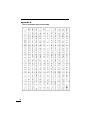
Table of Contents
Introduction ........................................................................................................ 2
About Your Security System .............................................................................. 2
Fire Detection ............................................................................................... 2
Monitoring .................................................................................................... 2
General System Operation .......................................................................... 3
Keypad LED Displays ....................................................................................... 3
System Master Menu Functions ........................................................................ 3
Partition Status Enunciator ................................................................................ 4
Global Keypads ................................................................................................. 4
What is a Global Keypad? ........................................................................... 4
How to use a Global Keypad? ..................................................................... 4
Display of Alarms/Bypassed Zones .................................................................. 9
Auto-bypass/Home-Away Arming ..................................................................... 9
Partition Keypads ............................................................................................ 10
Keypad Zones ............................................................................................ 10
Arming ........................................................................................................ 10
Disarming ................................................................................................... 12
User Programming Commands [✱]+[5]+[Access Code] ......................... 13
Programming Additional Access Codes Using
a System Master Code or a Supervisory Code ....................................... 15
Zone Bypassing [✱]+[1] ............................................................................ 17
Trouble Display [✱]+[2] ............................................................................. 18
Alarm Memory Display [✱]+[3] .................................................................. 21
Sensor Reset [✱]+[4] when disarmed ....................................................... 21
User Functions Command [✱]+[6]+[Access Code] ................................. 21
Walk Test [✱]+[6]+[Walk Test Code] when disarmed .............................. 23
Door Strike [✱]+[7] or [✱]+[7]+[Access Code] ........................................ 24
Installer’s Programming Commands [✱]+[8]+[Installer’s Code] .............. 24
“At-Home” Arming [✱]+[9]+[Access Code] .............................................. 24
Quick Arm [✱]+[0] ..................................................................................... 25
Quick Exit [✱]+[0] when armed ................................................................. 25
Keypad Lockout .............................................................................................. 25
Fire Safety in the Home ................................................................................... 25
Household Fire Safety Audit ............................................................................ 25
Family Escape Planning .................................................................................. 26
Maintenance .................................................................................................... 27
Limited Warranty .............................................................................................. 27
Appendix A
List of Available ASCII Characters ............................................................ 28
1
Introduction
The LCD4500 keypad provides easy to understand English language
information about the status of your security system and makes daily
operation simple by prompting the user through each operation.
The keypad provides audible feedback each time a key is pressed and with
unique audible sequences it signals troubles and the correct or incorrect
entry of information.
About Your Security System
Your DSC security equipment has been designed to give you the greatest
possible flexibility and convenience. The LCD4500 keypad will guide you
through each operation with English language prompts. Read this manual
carefully and have your installer instruct you on system operation and on
which features have been implemented on your system. All users of this
system should be equally instructed in its use.
FIRE DETECTION
This equipment is capable of monitoring fire detection devices such as
smoke detectors and providing a warning alarm if a fire condition is
detected. Good fire detection depends on having adequate numbers of fire
detectors placed in appropriate locations. This equipment should be
installed in accordance with N.F.P.A. standard #74 (N.F.P.A. Batterymarch
Park, Quincey MA 02269). Carefully review the Family Escape Planning
guidelines in this manual.
Note: Your installer must enable the fire detection portion of this
equipment before it becomes functional.
✎ Important Note
A security system cannot prevent emergencies. It is only intended to alert you and,
if included, a monitoring station of an emergency situation. Security systems are
generally very reliable but they may not work under all conditions and they are not a
substitute for prudent security practices or life and property insurance. Your
security system should be installed and serviced by qualified security professionals
who should instruct you on the level of protection that has been provided and on
system operation.
MONITORING
This system is capable of transmitting alarms, troubles, and emergency
information over telephone lines to a monitoring station. If you inadvertently
initiate an alarm, immediately call the monitoring station to prevent an
unnecessary response.
Note: The monitoring function must be enabled by the installer before it
becomes functional.
2
GENERAL SYSTEM OPERATION
Your security system is made up of a PC4010 and one or more LCD4500
and various detectors and sensors. The DSC control panel will be mounted
out of the way in a utility room or basement. The metal cabinet contains the
system electronics, fuses and stand-by battery. There is normally no reason
for anyone but the installer or service person to have access to the control
panel. The LCD4500 keypads have an audible indicator, an alphanumeric
LCD, (Liquid Crystal Display), and command entry keys. The keypad is used
to send commands to the system and to display the current system status.
The keypad(s) will be mounted in convenient locations inside the protected
premises close to the exit-entry doors.
The security system has several zones or areas of protection and each of
these zones will have one or more detection sensors connected to it (motion
detectors, glassbreak detectors, door contacts or shock sensors).
Keypad LED Displays
READY LIGHT (LCD45X1 KEYPADS ONLY)
If the Ready light is ON, the partition is ready for arming.
If the Ready light is OFF, check to see that all doors and windows are
closed and that all movement is stopped in areas covered by motion
detectors. The partition cannot be armed unless the Ready light is ON
indicating that all zones are closed and the partition is in the Ready state.
ARMED LIGHT
If the Armed light is ON, the partition has been armed successfully.
TROUBLE LIGHT
If the Trouble light is ON, check to see what the trouble condition is and call
for service.
System Master Menu Functions
System Master Codes may perform any function for any partition on the
system except changing or deleting the System Grand Master Code.
The System Master Menu can be accessed by entering [System Master
Code] [9]. Use the [<] [>] keys to display the items of the System Master
Menu. Press [✱] to select an item:
[0] View Event Buffer
[1] Set System Time
[2] Set System Date
[3] Enable DLS Window
[4] System Reset
[5] Previous Menu
[0] View Event Buffer - This function allows any Master Code to review the
Event Buffer on the keypad display. The first line of the display will show
the event number and the partition on which the event occurred; the
second line of the display will show the date and time of the event. Press
the [✱] key to display a description of the event. Use the [<] [>] keys to
scroll through the list of events in the Event Buffer.
[1] Set System Time programs the system’s 24 hour clock. Enter 4 digits in
24 hour time to set the clock, the first 2 digits are the hour, the last 2
digits are the minutes. For example, to program 2:35 pm, type in 1435.
3
[2] Set System Date programs the system’s calendar. Enter 6 digits, the
first two digits are the month, the middle 2 digits are the day, and the last
two digits are the year. For example, to program February 14, 1992 type
021492.
[3] Enable DLS Window - The end user can enable ring detect for 60
minutes to allow a computer to call the panel. The installer can disable
this function in the DLS section of the installer’s programming.
[4] System Reset - A System Reset turns off the power to the COMBUS for 5
seconds and resets the main panel. No programming will be lost and the
time will not have to be reprogrammed. A system reset should be done if
there is a COMBUS Communications fault or an Internal fault.
[5] Previous Menu - If the user decides to do nothing, either select this
option, or press the [#] key to return to the arm/disarm state.
Partition Status Enunciator
If the partition status enunciator is enabled, the status of all active partitions
will be displayed on the keypad.
The keypads will display
12 3 4
AR N F
A = Armed
R = Ready
N = Not Ready
F = Force armed
! = Alarm memory on Partition
Only enabled partitions will be displayed on the partition status enunciator.
Global Keypads
WHAT IS A GLOBAL KEYPAD?
A global keypad is a keypad which belongs to all partitions. It can be
accessed by all system users who have a valid access code with the global
access attribute enabled. The keypad will prompt the user to arm or disarm
their partition(s). The global keypad can also be “loaned” to a partition by
selecting options from the global menu then selecting the desired partition.
The users can only access partitions which are assigned to their codes.
HOW TO USE A GLOBAL KEYPAD?
The Global Keypad will display the message
ENTER YOUR
ACCESS CODE
or the full system status will be displayed if the global system status option is
enabled, or the clock will be displayed if global clock display is enabled. From
this state any user entering a valid access code with the global access attribute
enabled on their code, may access the system. The system can be directed to
perform functions such as arming/disarming and all [✱] mode functions. No
function can be performed without first entering a valid access code.
4
• Single Partition Access Code
ENTER YOUR
ACCESS CODE
The user enters a valid single partition access code.
[*] TO VIEW
< >
SYSTEM TROUBLES
This message will be displayed if there are troubles on the system and the
installer has enabled the option “GLB KYPD TRB” in the system toggles
section.
VIEW TROUBLE
< >
(TROUBLE MESSAGE)
Press [✱] to view the troubles on the system. The user can scroll through
the troubles by using the [<][>] keys.
(PARTITION LABEL)
[*] TO ARM
< >
This message will be displayed if the partition is ready to be armed. Press
the [✱] key to arm.
WARNING
BYPASS ACTIVE
This message will be displayed for 3 seconds if the partition is armed with
zones bypassed.
PARTITION ARMED
WITH OPEN ZONES
This message will be displayed for 3 seconds if the partition is armed with
force armable zones open.
EXIT DELAY
IN PROGRESS...
This message will be displayed for 3 seconds when a partition is armed.
ENTER YOUR
ACCESS CODE
After the exit delay in progress message has been displayed the keypad
will return to this message.
(PARTITION LABEL) <>
* FOR OPEN ZONES
If the partition is not ready to be armed because of open zones on the
partition, this message will be displayed.
ZONE OPEN
(ZONE LABEL)
< >
O
Press the [✱] key to view the open zones on the partition. Open zones can
be viewed by pressing the [<] [>] keys.
[*]TO BYPASS
ALL OPEN ZONES
5
After all open zones have been viewed the user will be given the option to
bypass all open zones. To bypass all open zones press the [✱] key.
(PARTITION LABEL) <>
UNABLE TO ARM
This message will be displayed if the partition is not ready to be armed
because of something other then open zones on the partition.
(PARTITION LABEL)
[*] TO DISARM
< >
This message will be displayed if the partition is armed.
NO ALARMS
IN MEMORY
Press the [✱] key to disarm the partition. If the partition is disarmed and no
alarms occurred during the current armed period this message will be
displayed for 3 seconds.
ALARM MEMORY
< >
(PARTITION LABEL)
If the partition is disarmed with alarms in memory, this message is
displayed. Press the [<][>] keys to scroll through the partitions that have
alarm memory on them.
[*]FOR OTHER
OPTIONS < >
If the user wishes to perform a function to a partition that is not available
through the global menu, the keypad can be loaned to the desired
partition be pressing the [✱] key at this option.
ACCESSING
(PARTITION LABEL)
When a keypad is loaned to another partition this message will be
displayed for 3 seconds. Once the keypad is loaned to another partition, it
will function as if it was a keypad that belonged to that partition. The user
will be able to perform all [✱] functions (e.g. [✱] [7] Door Strike) and
disarm the panel using conventional methods.
EXITING FROM
(PARTITION LABEL)
The keypad will return to global mode after 20 seconds of no key presses
made (this time is programmable by the installer). The keypad will also
return to global mode if the [#] key is pressed. This message will be
displayed for 3 seconds then the keypad will return to global mode.
• Multi-partition Access Code
ENTER YOUR
ACCESS CODE
The user enters a valid multi partition access code.
6
[*] TO VIEW
< >
SYSTEM TROUBLES
This message will be displayed if there are troubles on the system and the
installer has enabled the option “GLB KYPD TRB” in the system toggles
section.
VIEW TROUBLE
< >
(TROUBLE MESSAGE)
Press [✱] to view the troubles on the system. The user can scroll through
the troubles by using the [<][>] keys.
[*] TO ARM
< >
YOUR PARTITIONS
This message will be displayed if all partitions that the access code
belongs to are ready to be armed. Press the [✱] key to arm all partitions
that the code belongs to. The panel will only arm partitions that belong to
the entered access code.
UNABLE TO ARM
YOUR PARTITIONS
This message will be displayed if any one of the partitions that the access
code belongs to is not ready to be armed.
[*] TO DISARM
< >
YOUR PARTITIONS
This message will be displayed if any of the partitions that the access
code belongs to are armed. Press the [✱] key to disarm all partitions that
the access code belongs to. The panel will only disarm partitions that
belong to the entered access code.
(PARTITION LABEL)
[*] TO ARM
< >
Press the [<][>] keys to scroll through the partitions. Note that only
partitions that belong to the access code entered can be viewed. This
message will be displayed if the partition is ready to be armed. Press the
[✱] key to arm.
WARNING
BYPASS ACTIVE
This message will be displayed for 3 seconds if the partition is armed with
zones bypassed.
PARTITION ARMED
WITH OPEN ZONES
This message will be displayed for 3 seconds if the partition is armed with
force armable zones open.
EXIT DELAY
IN PROGRESS...
This message will be displayed for 3 seconds when a partition is armed.
7
ENTER YOUR
ACCESS CODE
After the exit delay in progress message has been displayed the keypad
will return to this message.
(PARTITION LABEL) < >
* FOR OPEN ZONES
If the partition is not ready to be armed because of open zones on the
partition, this message will be displayed.
ZONE OPEN
(ZONE LABEL)
< >
O
Press the [✱] key to view the open zones on the partition. Open zones can
be viewed by pressing the [<] [>] keys.
[*]TO BYPASS
ALL OPEN ZONES
After all open zones have been viewed the user will be given the option to
bypass all open zones. To bypass all open zones press the [✱] key.
(PARTITION LABEL) < >
UNABLE TO ARM
This message will be displayed if the partition is not ready to be armed
because of something other then open zones on the partition.
(PARTITION LABEL)
[*] TO DISARM
< >
This message will be displayed if the partition is armed.
NO ALARMS
IN MEMORY
Press the [✱] key to disarm the partition. If the partition is disarmed and no
alarms occurred during the current armed period this message will be
displayed for 3 seconds.
ALARM MEMORY
< >
(PARTITION LABEL)
If the partition is disarmed with alarms in memory, this message is
displayed. Press the [<][>] keys to scroll through the partitions that have
alarm memory on them.
[*]FOR OTHER
OPTIONS < >
If the user wishes to perform a function to a partition that is not available
through the global menu, the keypad can be loaned to the desired
partition.
[*]TO SELECT
(PARTITION LABEL)
Press the [<][>] keys to scroll to the desired partition, then press the [✱]
key.
8
ACCESSING
(Partition label)
When a keypad is loaned to another partition this message will be displayed for
3 seconds. Once the keypad is loaned to another partition, it will function as if it
was a keypad that belonged to that partition. The user will be able to perform all
[✱] functions (e.g. [✱] [7] Door Strike) and disarm the panel using conventional
methods.
EXITING FROM
(Partition Label)
The keypad will return to global mode after 20 seconds of no key presses
made (this time is programmable by the installer). The keypad will also
return to global mode if the [#] key is pressed. This message will be
displayed for three seconds, then the keypad will return to global mode.
Display of Alarms / Bypassed Zones
Your installer may enable bypassed zones or zones in alarm to be viewed
on armed partitions. If so, pressing the [<] [>] keys will display any zones on
the partition that have gone into alarm with the message “View Alarms”
followed by the zone label. Any zones on the partition which were manually
bypassed may also be viewed by pressing the [<] [>] keys.
Note that Home-Away zones which are normally bypassed upon arming the
system will not be displayed.
Auto-bypass/Home-Away Arming
If a correct access code is entered and you do not exit the premises
through a designated exit-entry door, the system will, at the end of the Exit
delay time, arm with interior zones automatically bypassed if those interior
zones have been programmed as “Home-Away” zones. These zones will
remain bypassed until a delay zone is tripped or [✱] [1] is entered to
reactivate bypassed home-away zones.
This is a convenience feature for someone who wishes to remain on the
premises with the system armed. That person does not have to manually
bypass the home-away zones.
If partitions are remotely armed using a global or multi partition access code
i.e. a code that can arm/disarm partitions 1, 2 and 3. The home-away zones
will be active on those partitions except the one being armed from if the user
does not exit through a delay zone.
To reactivate the Home-Away zones that have been automatically bypassed,
press [✱] [1]. This command is a quick method of fully arming the system in
residential applications.
9
Partition Keypads
KEYPAD ZONES
All Fire, Auxiliary and Panic keys are only functional if they have been
programmed by the installer. The installer should indicate which of these
keys are active by placing a coloured label next to the key.
• Fire - Holding [F] key or both
keys down for 2 seconds will sound a fire
alarm. The alarm will sound pulsing and a transmission will be sent to the
monitoring station. The keypad will sound three beeps once the panel has
accepted the alarm.
• Auxiliary - Holding [A] key or both
keys down for 2 seconds will send
a transmission to the monitoring station.
• Panic - Holding [P] key or both
keys down for 2 seconds will send a
transmission to the monitoring station. The installer can program this key
to sound the alarm or to transmit the alarm silently.
The global keypad will always send (if programmed) the system area
account code. The Fire, Auxiliary and Panic keys will activate for all active
partitions. Any valid access code from any partition may silence the alarm.
ARMING
Close all protected doors and windows and stop movement in areas
covered by motion detectors.
The “Enter Code to Arm System” message should be on the LCD display.
The system cannot be armed unless the “Enter Code to Arm System” or
“Secure System or Enter Code...” message is displayed.
If Double EOL resistors are being used, 3 different messages can be displayed
when viewing open zones, Zone Open, Zone Tamper and Zone Fault. Zone Open
will be displayed if the zone is in the alarm state, Zone Fault will be displayed if
the zone is shorted, and Zone Tamper will be displayed if the zone is open.
Enter a 4 digit or 6 digit access code. As each digit is entered the keypad
will beep.
• If the access code was entered incorrectly, the keypad will beep steadily
for 2 seconds.
• If the code was entered correctly but the system was not secure due to an
open zone, the keypad will beep quickly followed by a steady tone.
• When the correct code is entered, the “Exit delay in Progress” message
will be displayed and the keypad will beep three times quickly. If a
System Master Code was entered, the system master menu will appear.
See “System Master Codes”.
A timer will appear in the right side of the display indicating the remaining
time in the exit delay. Exit the premises through the designated exit-entry
door. When the allowed exit time expired the message on the keypad will
change to “Enter Code to Disarm System”.
10
If a multi partition access code is entered the keypad will display the
message
(0) TO ARM
< >
(Partition Label) R
.
The lower right hand corner of the display will show the partition status using
the letter “R” for Ready, “N” for Not ready, “A” for Armed and “!” for partition
is in alarm.
Use the [<] [>] keys to scroll though the assigned partitions. Only partitions
to which the access code is assigned will be displayed. The message
(2) TO SELECT
< >
(Partition Label) R
with the partition status at the lower right hand side of the LCD.
To arm the partition which you are in simply press [✱] or use the hotkey (0).
The message
EXIT DELAY
IN PROGRESS
will appear on the keypad with the exit delay timer if it is enabled. Instead of
arming their own partition, if the user decides to select another partition to
arm the message
SELECT (0)
ARM PARTITION
< >
R
will be displayed. Use the arrow keys to scroll to the “For Options” menu.
Selecting (0) “To Arm” will arm the selected partition and display the message
EXIT DELAY
IN PROGRESS
for 2 seconds and then return the user to the arming menu of their own
partition.
If (1) “For Options” is selected the user will be prompted with the message
ACCESSING
(Partition Label)
.
From here the user is capable of performing all [✱] functions (e.g. [✱] [7]
Door Strike) and arm the panel using conventional methods.
Once the [#] key is pressed or the programmable amount of idle time (no
key presses made or not active in a submenu) the keypad will return to its
home partition displaying the message
RETURNING TO
(Partition Label)
.
11
DISARMING
Enter the premises through the designated exit-entry door. The keypad
buzzer will be on. Go to the keypad and enter the 4 digit or 6 digit
access code. If an error is made in entering the code, press the [#] key
and enter the code again. The “Armed” light will go out and the keypad
buzzer will stop. The correct access code must be entered before the
allowed entry time expires. To change the entry time see “Installers
Programming Command”, [✱][8]. If an alarm occurred while the panel
was armed, the “View Memory” message will be on the display with the
zone label for the zone that caused the alarm. The display will keep
those messages on for two minutes or until the [#] key is pressed to
return the panel to the normal arm-disarm mode.
To disarm another partition with a multi-partition access code, select the
partition. The message
SELECT (0)
Disarm Partition
will be displayed. Press [✱] or [0] to disarm the partition.
12
USER PROGRAMMING COMMANDS
[✱]+[5]+[ACCESS CODE]
The [✱] [5] [Access Code] command is used to program the Master Codes
and regular access codes.
The first access code is the System Grand Master Code. Normally, only the
installer can change the System Grand Master Code. The installer may also
program the system to allow the user to change the System Grand Master Code.
The System Grand Master Code has no limitations to its use. It may be used
to create or delete other System Master Codes or to perform any user
function on the system. Note that only to the first access code can be the
System Grand Master Code.
Note: When using a global keypad the System Master should assign
access codes to avoid duplication.
Each access code may be programmed as one or a combination of the
following options:
• System Master Codes may perform any function for any partition on the
system except change or delete the System Grand Master Code, or
change or delete other System Master Codes.
• Supervisory Codes allow the user to program and edit other access
codes, except System Master and Duress Codes, for any partitions which
the access codes belong to. Supervisory Codes are also used for arming,
disarming, bypassing and all other functions that a System Master Code is
capable of.
• Arm Only Code allows the user to arm only the partitions to which the
code is assigned.
• Disarm Only Code allows the user to disarm only the partitions to which
the code is assigned.
• Door Strike Code allows the user to operate door strikes only within the
partition to which the code is assigned. (The PC4010 has not been
investigated to the requirements of UL294.)
• Duress Codes are used to disarm partitions and send a duress code
transmission to the monitoring station. A user would enter a Duress Code to
indicate that they are being forced by an intruder to disarm the system.
When a Duress Code is entered, the partition or partitions to which it is
assigned will disarm normally, and a Duress Code transmission will be sent
to the monitoring station. Also, any outputs programmed as “Duress
Outputs” will be activated when the Duress Code is entered. A Duress Code
may be programmed for arming and disarming; note that the “Duress Code”
will be transmitted to the monitoring station for any event it performs.
13
• One -Time Use Codes are used to allow infrequent users of the system,
such as service personnel, to arm the system. When the system is armed
using a One -Time Use Code, the code will be erased once the Exit Delay
expires; after this time, the code may not be used again. If the One -Time
Use Code is entered before the Exit Delay expires, arming of the system
will be cancelled; the One -Time Use Code may then be entered again
later to arm the system.
• Log Only Codes are used strictly for logging to the event buffer. The
system master can log the time, date and location which they were at with
the Log Only codes. To enable this code type, enable just door strike or
disable all options.
Note: Do not program access codes such as 1111 or 1234 which can
be easily guessed and will compromise the security of your system.
• Escort 4580 Access allows the user to access the Escort 4580 (Voice
Prompting Module) via the in house telephone or remotely through a
telephone. The user will have the same abilities through the VPM-2 as they
would through a regular keypad.
Note: Do not program One -Time Use Codes without arming or disarming
enabled.
• Global Access allows the access code to be used on global keypads.
Disabling this toggle option for any access code will inhibit the code from
being used on any global keypad.
• Partition Selection Menu brings up the partition selection menu when a
multi-partition access code is entered on a partition keypad. When this
option is disabled, multi-partition access codes will function as a single
partition access code for the partitions the access code is enabled on.
14
PROGRAMMING ADDITIONAL ACCESS CODES USING A SYSTEM
MASTER CODE OR A SUPERVISORY CODE
1 Press [✱] then [5] to enter the User Programming Commands; the
keypad will display the message “Enter Your Access Code”. Any System
Master Code or Program Code may be entered.
• If the Grand Master Code is entered, System Master Codes and
regular access codes for any partition will be able to be programmed.
• If a System Master Code is entered, regular access codes for any
partition will be able to be programmed. A System Master Code can
also create Supervisory and Duress Codes.
• If a Supervisory Code is entered, only access codes belonging to the
partition to which the Supervisory Code is assigned may be changed.
When a valid access code is entered, the keypad will display the number
of available access codes on the first line of the screen.
2 The keypad will display the message “Sel Code (xxx) < >”. “(xxx)”
represents the number of the access code that has been selected for
programming and the access code name on the second line. Use the [<]
[>] keys to scroll through the list of access codes, or enter the code
number 001 to 128. When the desired access code number is displayed,
press the [✱] key to program the code.
3 When an access code is selected for editing by pressing the [✱] key, a
menu for editing access codes will be displayed. Select one of the menu
items by entering a number on the keypad.
[0] Program Code - When [0] is pressed, the keypad will display the
message “Enter Digits” and the presently-programmed access code.
Enter the new 4 digit or 6 digit access code. Do not press [✱] or [#]
while entering the access code. If you do not wish to change the
code, press [#] key.
[1] Erase Code - If an access code is no longer needed, this selection
will erase the code, but not the user’s name.
[2] Edit Access Code Name - When a PC4400 RS232 module is enrolled
on the system, the name of the code which is used to arm and disarm
will be printed out. Also, the access code name helps keep track of the
code when programming codes. Move the cursor to left or right by
pressing the [<][>] keys. The letters of the alphabet have been divided
up among the 1 to 9 number keys on the keypad as below:
[1] = A, B, C, 1
[2] = D, E, F, 2
[3] = G, H, I, 3
[4] = J, K, L, 4
[5] = M, N, O, 5
[6] = P, Q, R, 6
[7] = S, T, U, 7
[8] = V, W, X, 8
[9] = Y, Z, 9, 0
[0] = Space
15
For example, if you press the [4] key once, the letter ‘J’ will appear
above the cursor on the display. Press the [4] key again, the next
letter ‘K’ will appear, and so on. If a different number key is pressed,
e.g. the [6] key, the cursor will automatically move to the right one
space, i.e. the letter ‘P’. To erase a character, use the [<] [>] keys to
move the cursor under the character, then press the [0] key.
While programming the access code label, press the [✱] key to call
up an options menu. To select an option, press the corresponding
number key or scroll through the options using the [<][>] keys, then
press the [✱] key to select.
[0] Clear Display will clear the entire code label.
[1] Clear to End will clear the display from the character where the
cursor was located to the end of the display.
[2] Change Case will toggle the letter entry between upper case letters
(ABC...) and lower case letters (abc...).
[3] ASCII Entry (see Appendix A) is for entering uncommon characters.
There are 255 characters, but 000 to 031 are not used. Use the [<][>]
keys to toggle through the characters or enter a 3 digit number from 032
to 255. Press the [✱] key to enter the character into the code label.
[3] Edit Access Code Options - When [3] is pressed, the keypad will
display the message “Select toggle < >”. Use the [<] [>] keys to
scroll through the list of options:
• System Master?
• Bypass?
• 4580 Access?
• Program Codes?
• Door Strike?
• Global Access?
• Arm?
• Duress Pulse?
• Partition Selection
• Disarm?
• One Time Use?
Menu?
[4] Edit Partition Mask - The Partition Mask is used to assign the access
code to one or more partitions. In order for an access code to
function, the Partition Mask must be assigned to the access code; if
no partition mask is assigned, the code will not operate on any
partition.
[5] To Exit the menu, press the [#] key.
4 To exit the Access Code Programming Mode, press [#].
16
ZONE BYPASSING
[✱]+[1]
A bypassed zone will not cause an alarm. If a zone is bypassed the panel
may be armed even if the zone is open. Use zone bypassing when access
is needed to part of the protected area. Also, damaged wiring or contacts
on a zone may be temporarily bypassed until repairs can be made so that
the panel can be armed.
To bypass zones, enter [✱] [1]. An access code may be required if the
installer has enabled that option. A menu will appear.
[0] Bypass Zones - This selection takes you immediately to bypassing
zones. Use the [<] [>] to select the zones to be bypassed and press the [✱]
key to select the zone. A “✱” will appear beside the zone label to indicate
the zone will be bypassed when the partition is armed.
A zone search routine allows the user to find the desired zone to bypass by
entering in the first letter of the zone to search for, and pressing one of the
[<][>] keys. The [>] key will search for the first zone on the partition that
begins with the letter selected. Pressing the [>] key again will search for the
next zone on the partition that begins with the letter selected.
The letters of the alphabet have been divided up among the 1-9 number
keys on the keypad.
1
2
3
ABC1
DEF2
GHI3
4
5
6
JKL4
MNO5
PQR6
7
8
9
STU7
VWX8
YZ90
0
CLEAR
[1] Clear Bypasses will remove bypasses from all the zones in your partition
and then takes you to bypassing zones. None of the zones will have a “✱”
beside them.
[2] Recall Bypasses will bypass all the same zones selected for the last
time zone bypassing. This is for users who always bypass the same zones.
[3] Previous Menu takes the user back to the “Enter Code to Arm System”.
When the PC4010 was programmed, the ability to bypass certain zones may
have been eliminated by the installer. In this case, the “✱” message for
those zones will not come on in response to the bypass command. Zone
bypasses are automatically cancelled when the panel is disarmed.
Note: At no time can any armed zone be bypassed.
17
While the system is disarmed, bypassing can be used to temporarily silence
the door chime feature on a zone. Simply bypass the zone that the door
chime feature enabled. The keypad will no longer beep when the zone is
opened. Be sure to clear all bypasses before arming, to ensure no zones
are unintentionally bypassed.
TROUBLE DISPLAY
[✱]+[2]
The PC4010 continuously monitors a number of possible trouble conditions.
If one of these conditions occurs, the keypad “TROUBLE” indicator will light
and the audible indication will sound (two short beeps every 10 seconds).
When the [#] key is pressed the audible indication will stop on that partition,
but the trouble indicator light will remain ON until the trouble is cleared.
Trouble conditions can also be transmitted to the monitoring station. Press
the [✱] then [2] keys to display the trouble conditions.
• Waterflow TBL
• Fire Trouble 2WS
• Battery Trouble
• Cellular Trouble
• AC Trouble
• Loss of Time
• Aux Supply Troub
• DLS Fault TBL
• Module Com Fault
• TLM Trouble
• Zn Sensor Fault
• COMBUS Low Pwr
• TLM TBL Line #1
• Zn LwBatt Fault
• Internal Fault
• TLM TBL Line #2
• 4204 Battery TBL
• X10 Fault
• FTC Trouble
• 4204 AC Trouble
• Printer Off-Line
• Bell CCT Trouble
• 4204 Aux Trouble
• PC4400 Trouble
• Fire Trouble
• Ground Fault
Press [#] to return to “READY”.
Battery Trouble - A battery trouble will be displayed and can be reported if
the battery is 11.3 volts or less, disconnected or the battery fuse fails. Battery
voltage is checked once every 4 minutes, so the battery trouble may not
restore instantly when the battery is restored. Initiating a bell/comm test will
check the battery voltage. When DC Inhibit Arm is enabled the panel will
check the condition of the batteries on the system (main panel and PC4204)
when an access code is entered. If during this check the battery shows a
low voltage condition the arming will be inhibited. The LCD will display the
message "Fail To Arm... Battery Trouble" when this occurs.
The Control panel and each of the PC4204 modules may only have 3 battery
trouble alarms in a 24 hour period. After the third battery trouble for a given
module the trouble condition will "Shutdown" until midnight of that day. The
trouble will still be enunciated with the keypad Trouble LED but the event will
not be logged to the event buffer or be communicated.
AC Trouble - There is no audible annunciation on AC power failure. The
system “Trouble” light will come ON but the audible indication will not sound
until there is a low battery condition. Transmission delay can be
programmed for 000 to 255 minutes.
18
Aux Supply Troub - An Aux trouble is generated if the aux fuse on the main
panel opens, or if the Aux or SW Aux terminals are overloaded.
TLM Trouble - A telephone line trouble is generated when the line voltage
drops below 3 volts for more than 30 seconds. A keypad trouble is
generated when the system is disarmed and if selected, a local alarm
sounds when the panel is armed.
TLM TBL Line #1 - When using the PC4700 Fire Module a telephone line trouble
is generated when the line voltage drops below 3 volts for more than 30 seconds
on line one. A keypad trouble is generated when the system is disarmed and if
selected, a local alarm sounds when the panel is armed.
TLM TBL Line #2 - When using the PC4700 Fire Module a telephone line
trouble is generated when the line voltage drops below 3 volts for more than
30 seconds on line two. A keypad trouble is generated when the system is
disarmed and if selected, a local alarm sounds when the panel is armed.
FTC Trouble - If the digital communicator is unsuccessful in communicating with
the monitoring station after 10 attempts, a Fail to Communicate trouble is
generated. If a later attempt to communicate is successful the trouble is cleared.
Bell CCT Trouble - If the bell fuse opens or the bell circuit is open, a
keypad trouble and a Bell Circuit trouble transmission are generated.
Fire Trouble - If a FIRE loop is open circuit, a keypad trouble and a Fire
Loop trouble transmission are generated. A trouble on the FIRE loop will
unconditionally initiate an audible and visual (trouble light) indication on the
keypad. This means that even if any other previous trouble has been
silenced, a FIRE loop trouble will restart the keypad buzzer.
Fire Trouble 2WS - If the fire zone on a PC4700 Fire Module is opened, a
visual keypad trouble (trouble LED will come on) with audible indication and
a fire zone trouble transmission is generated. The LCD will show the
message "FIRE TROUBLE!! 2 Wire Smoke", until the fire zone trouble is
restored. If there is more than one PC4700 trouble condition present these
trouble messages will scroll every 3 seconds to the next message.
Loss of Time - When the PC4010 is powered up, the internal time of day
clock needs to be set to the correct time. This trouble is cleared when an
attempt is made to reset the internal time of day clock. See “System Master
Codes” for resetting the time of day clock.
Module Com Fault - The panel has lost communications with a module and
cannot recover it. Check to see if the module is connected properly, then do
a system reset. See “Diagnostics” in the Programming Manual to determine
which module is not communicating.
19
COMBUS Low Pwr - Modules are not getting enough voltage from the
COMBUS. Check for proper connection of COMBUS, or the COMBUS needs
to be repowered. See 4204 modules and the 4204 PGM COMBUS power
option for supplying voltage to the COMBUS. See “Diagnostics” in the
Programming Manual to determine which module has low voltage.
Internal Fault - A problem has occurred with the COMBUS microprocessors. If
this trouble occurs, check connections to the COMBUS and do a system reset.
4204 Battery TBL - If any PC4204 relay output module’s battery drops
below 11.3 volts, a battery trouble is generated.
To determine which of the PC4204’s has the low battery, check the reporting
code transmitted to the monitoring station or check the event buffer printout
if there is a printer attached, or through downloading. The battery voltage is
checked once every 4 minutes. So the battery trouble may not restore
instantly when the battery voltage is restored.
4204 AC Trouble - If any PC4204 relay output module loses incoming AC power,
the keypad trouble light will indicate a 4204 AC trouble. But there will be no
audible annunciation until there is also a low battery condition.
The PC4204 AC troubles will be transmitted to the monitoring station immediately.
4204 AUX Trouble - If the Aux fuse on any PC4204 relay module should
open or if the Aux supply is overloaded, a 4204 Aux trouble is generated.
Ground Fault - A Ground Fault trouble condition will occur if the Earth Ground
(EGND) connection is shorted to a positive voltage source or shorted to a
non-earth ground potential. This trouble will generate an audible and visual
trouble as well as a Ground Fault reporting code transmission.
Waterflow TBL - If the Waterflow zone on a PC4700 Fire Module is opened
(WFA or WFB), a visual keypad trouble (trouble LED will come on) with
audible indication and a Waterflow trouble transmission is generated. The
LCD will show the message "FIRE TROUBLE!! Waterflow TBL", until the
Waterflow zone trouble is restored. If there is more than one PC4700 trouble
condition present these trouble messages will scroll every 3 seconds to the
next message.
Cellular Trouble - This indicates that the LINKS unit has one or more of the
following trouble conditions: AC, battery, loss of cellular or a tamper fault.
DLS Fault TBL - This trouble condition will generate an audible and visual
trouble when the control panel fails to complete communications with the
downloading computer.
Zn Sensor Fault - This trouble condition will occur when a wireless zone
fails to report a zone supervisory. To view which zone has the trouble press
the [✱] key while viewing the trouble condition. The zone(s) with the trouble
condition will be displayed in numerical order on the display. A keypad
trouble is generated when the system is disarmed and a visual "Zn Sensor
Fault" trouble and trouble reporting code will be transmitted.
20
Zn LwBatt Fault - This trouble condition will occur when a wireless zone
has a low battery condition. To view which zone has the trouble press the
[✱] key while viewing the trouble condition. The zone(s) with the trouble
condition will be displayed in numerical order on the display. A keypad
trouble is generated when the system is disarmed and a visual "Zn Low Batt
Fault" trouble and trouble reporting code will be transmitted.
Automation Fault - This trouble condition will occur well the Escort 4580 losses
communication with the Automation Output control module. An audible trouble
(VIA keypad buzzer) will be generated as well as the trouble LED activating for
the keypads. An Automation Fault trouble reporting code will be sent to the
monitoring station if programmed. If there is an AC trouble present at the time
the panel will not transmit the Automation Fault reporting code.
Printer Off-Line - This trouble condition will occur if the serial printer
connected to the PC4400 serial interface module goes off-line.
PC4400 Trouble - This trouble will be displayed when a DVAC Fault occurs
(The DVAC line from central station is not present), or a Module Fault occurs
(The PC4400 module has failed an internal diagnostics), or if DVAC
communications has been shut down by central.
ALARM MEMORY DISPLAY
[✱]+[3]
Press [✱] then [3] to enter the alarm memory mode. Any alarm caused during
the last armed period will be displayed. The “Alarm Memory” message will
only be displayed when an alarm occurred during the last armed period.
Press [#] to return to “Ready”.
Note: Tamper alarms will not be shown in alarm memory display.
SENSOR RESET
[✱]+[4] When Disarmed
Entering [✱] [4] [access code] will reset smoke detectors assigned to that
partition. The message “Sensor Reset In Progress...” will be displayed,
along with a countdown in the lower right corner. Your installer may program
the sensor reset option so that an access code is required.
USER FUNCTIONS COMMAND
[✱]+[6]+[ACCESS CODE]
Enter [✱][6][Access Code] and then use the [<][>] keys to display the items
of the function menu. Press [✱] to select an item.
[0] Quick Arm
[1] Quick Exit
[2]Auto Arm Control
[3] Keypad Setup
[4] Bell/Comm Test
[5]Door Chime
[6] Spec. Messages
[7] User Call Up
21
Items [0], [1], [5] and [6] turn on and off various functions. To enable or
disable these functions, press the [✱] key to toggle “Y ”or “N” on the keypad.
Y - The function is enabled
N - The function is disabled
[0] Quick Arm feature is enabled by toggling to “Y” on the keypad. When
enabled the panel can be armed by entering [✱] [0].
[1] Quick Exit function is enabled by toggling to “Y” on the keypad. When
enabled the user can exit through any delay zone without altering the
status of the system, by entering [✱] [0] on the keypad.
[2] Auto Arm Control - The PC4010 can be programmed to arm a partition
at the same time each day, by enabling the auto arm function and
programming the auto-arm time.
At the selected auto arm time, the system will give a pre-alert. The
keypad begins to sound and the Bell/Siren will pulse once every 10
seconds to alert anyone on the premises that the system is about to arm.
The bell/siren pulse can be programmed by the installer to be silent.
The keypad will sound for 1 minute before auto arming unless the autoarm is aborted. To abort the auto arm and silence the keypad press any
key during the pre-alert. The auto arm will be attempted at the same time
the following day. The PC4010 can be programmed by the installer to
require a code to be entered for aborting the auto arm.
Upon selecting the auto arm control function, the auto arm control menu
will appear on the LCD keypad:
[0] Auto Arm toggles “Y” or “N” to enable or disable the Auto Arm/Auto
Disarm function.
[1] Schedule Arm when this toggle option is enabled the partition will
follow the Auto Arm schedule programmed (by the installer) for that
partition. When this option is enabled the partition will not follow the Auto
Time (programmed in section 2). For the Auto Arm Time to function this
option must be disabled.
[2] Auto Arm Time is the time the partition will automatically arm itself
every day.
[3] Sched. Disarm when this toggle option is enabled the partition will
follow the Autodisarm schedule programmed (by the installer) for that
partition.
Note: The auto arm time is a 24 hour clock and times must be
entered as two digit numbers.
E.g. HH - 00, 01,.....10, 11,.....22, 23
MM - 00, 01,.....35, 36,.....58, 59
Enter 4 digits representing the time in hours and minutes (HH:MM) based
on 24 hour or military time. Always enter a leading zero where only one
digit is required, 8:05 am would be entered as 0805, 1:30 pm would be
entered as 1330.
Note: The panel will not autoarm, schedule arm, or schedule disarm,
if there is a loss of time trouble present on the system.
22
[3] Keypad Setup allows the user to adjust the backlighting and contrast of
the LCD4500 keypad. When this function is selected, the keypad setup
menu will appear on the keypad:
• Bright Control adjusts the level of back lighting on the LCD display
and the backlighting on the keys.
• Contrast Control adjusts the contrast of the lettering on the LCD
display.
Use the [<][>] keys to toggle through the 8 different settings, and press
[✱] to select the level of preference.
[4] Bell/Comm Test allows the end user to test the system. This option
activates the bells for 2 seconds and sends a test code transmission to
the monitoring station.
[5] Door Chime feature is enabled or disabled by pressing the [✱] key to
toggle from “N” to “Y” or “Y” to “N”. When the chime zone is activated,
the keypad will beep quickly 5 times. The “Beeping” on doors can be
eliminated temporarily by using zone bypass, only when the panel is
disarmed.
[6] Special Messages function enables 2 special event messages to be
displayed when one of the special events occurs.
The first message is “Fail to Arm”. It will be displayed if the user is
unable to arm the partition after entering a valid code, e.g. because of
activity on the zones.
The second message is “Alarm When Armed”. It will be displayed if an
alarm occurred during the previous armed period.
[7] User Call Up function must be enabled by the installer. The panel will
call the downloading computer when selected. The downloading
computer must be waiting for the panel to call before downloading can
be performed.
WALK TEST
[✱]+[6]+[Walk Test Code] When Disarmed
The Walk Test feature allows the user to test if the detectors on a partition
are in proper working order. There are 4 options in the walk test menu. Press
[✱] to view and select the option.
[0] Local, No Bell
[2] Local+Comm. Test
[1] Local Walk Test
[3] Disable Walk Test
[0] Local, No Bell will not sound the bell when a zone is tripped and no
transmission will take place for the zone alarm. The zone alarms will be
logged to the event buffer and displayed in alarm memory.
23
[1] Local Walk Test is selected the keypad will sound 3 quick beeps and
return to the normal disarmed display. The user can then test each
detector on the partition and any zone violated will cause the burglary
bell/siren to sound for 2 seconds, confirming that the detectors are
working properly. Note that fire bell/sirens will not sound, and all zones
including fire zones will activate burglar bell/siren alarms for 2 seconds
in walk test mode.
During walk test mode no alarms on that partition will be transmitted to
the monitoring station. However, if a printer module (PC4400) is installed
on the system the zones violated will be printed.
[2] Local + Comm. (Communications) Test will operate the same as local
walk test mode except that alarms will be transmitted to the monitoring
station in order to test communications.
[3] Disable Walk Test will disable walk test mode, and the partition returns
to its normal disarmed state. Walk test mode will also be automatically
disabled if the partition is armed.
DOOR STRIKE
[✱]+[7] or [✱]+[7]+[ACCESS CODE]
Entering [✱] [7] or [✱] [7] [Access Code] will activate a utility output for a
preset time, during which the keypad buzzer will sound. The utility output
may be used on an armed or disarmed partition, and the installer may
program it so that an access code is required to activate the utility output.
Note: The Door Strike output will be deactivated at the end of the
standard exit delay.
INSTALLER’S PROGRAMMING COMMANDS
[✱]+[8]+[INSTALLER’S CODE]
This command is used by the installer to program the PC4010.
“AT-HOME” ARMING
[✱]+[9]+[ACCESS CODE]
Entering [✱] [9] before the arming code, arms the panel without any entry
delay on the delay zones and bypasses zones that are defined as “HomeAway”. This command is used for arming the system while at home. Once
the panel is Armed in this mode, using [✱] [1] will remove the bypass from
those zones defined as “Home-Away” if they have NOT been manually
bypassed. The [✱] [1] command, as used here, only removes the bypass
from zones that were automatically bypassed with the [✱] [9] command.
If [✱] [9] proceeds a multi partition access code used to arm any partition,
the partition(s) will be at-home armed.
24
QUICK ARM
[✱]+[0]
Entering [✱] [0] is accepted as a valid arming code when the “Quick Arm”
feature is activated. This command is often used when individuals are required
to arm the system but not disarm it. This could be used with home visitors in the
case of a residential alarm or junior employees and maintenance staff in the
case of a commercial alarm. See instructions in the “[✱] [6] Users Programming
Commands” section for activating the “Quick Arm” feature. The One-Time Use
Code users should not use this feature, because the One-Time Use Code will
only be erased when it is used to arm the system.
QUICK EXIT
[✱]+[0] WHEN ARMED
Entering [✱] [0] when the system is fully armed will allow the user 2 minutes
to exit the premises through any delay zone without altering the status of the
system if the “Quick Exit” feature is enabled. After [✱] [0] is entered into an
armed system, one and only one delay loop may be tripped. Any additional
activity on any other active loop will cause that loop to begin its alarm
sequence. Quick exit activation will be logged onto the event buffer.
Keypad Lockout
If this feature is enabled on a partition and a programmable number of incorrect
access codes are entered, the message “Keypad Lockout Is Active...” will be
displayed on all partition keypads. The keypad will respond with an error tone to
all further keypresses for a programmable amount of time.
Fire Safety in the Home
Most fires occur in the home and to minimize this danger it is recommended
that a household fire safety audit be conducted and a family escape plan be
developed.
Household Fire Safety Audit
1. Are all electrical appliances and outlets in a safe condition e.g. frayed
cords, over-loaded lighting circuits? If you are uncertain about the
condition of your electrical appliances or household service, have a
professional evaluation.
2. Are all flammable liquids stored safely in closed containers in a well
ventilated cool area? Cleaning with flammable liquids should be avoided.
3. Are fire hazardous materials (matches) well out of reach of children?
4. Are furnaces and wood burning appliances properly installed, clean and
in good working order? Have a professional evaluation.
25
Family Escape Planning
There is often very little time between the detection of a fire and the time it
becomes deadly. It is thus very important that a family escape plan be
developed and rehearsed.
1.Every family member should participate in developing the escape plan.
2.Study the possible escape routes from each location within the house and
since many fires occur at night, special attention should be given to the
escape routes from sleeping quarters.
3.It is essential that escape from a bedroom be possible without opening
the interior door. To facilitate such an escape:
• Make sure that doors and/or windows that open to the outside are easily
opened, e.g. not painted shut.
• Simply making the exit may be too difficult for children, the elderly or
handicapped, plans for rescue should be developed. This includes
making sure that those who are to perform the rescue can promptly hear
the fire warning signal.
• If the exit means is above the ground level, an approved fire ladder or
rope should be provided as well as training in its use.
• Exits on the ground level should be kept clear, e.g. remove snow from
exterior patio doors.
• The family should have a predetermined assembly point where
everyone can be accounted for, e.g. across the street or at a neighbour.
• Once everyone is out of the house call the Fire Department.
• A good plan emphasizes quick escape. Do not investigate first or
attempt to fight the fire and do not attempt to rescue valuables or pets
as this takes up valuable time. Once outside, do not re-enter the house.
Wait for the fire department.
• Write the plan down and rehearse frequently so that should an
emergency arise, everyone will know what they are to do. Revise the
plan as conditions change, e.g. more or fewer family member or
changes to the house.
• Make sure your fire warning system is operational by conducting weekly
tests as noted elsewhere in this manual. If you are unsure about system
operation, contact your installing dealer.
• It is recommended that you contact your local fire department and
request further information on home fire safety and escape planning. If
available, have your local fire prevention officer conduct an in-house fire
safety inspection.
Maintenance
26
With normal use, the system requires minimum maintenance. The following
points should be observed.
1. Do not wash the keypad with a wet cloth. Light dusting with a barely damp
cloth should remove normal accumulations of dust.
2. The battery/bell test is designed to determine battery condition, however it
is recommended that the stand-by batteries be replaced every three years.
3. For other system devices such as smoke detectors, passive infrared,
ultrasonic or microwave motion detectors, or glassbreak detectors, consult
the respective manufacturer’s literature for testing and maintenance.
LIMITED WARRANTY
Digital Security Controls Ltd. warrants the original
purchaser that for a period of twelve months from
the date of purchase, the product shall be free of defects in materials and workmanship under normal use.
During the warranty period, Digital Security Controls Ltd. shall, at its option, repair or replace any
defective product upon return of the product to its
factory, at no charge for labour and materials. Any
replacement and/or repaired parts are warranted for
the remainder of the original warranty or ninety (90)
days, whichever is longer. The original owner must
promptly notify Digital Security Controls Ltd. in
writing that there is defect in material or workmanship, such written notice to be received in all events
prior to expiration of the warranty period.
International Warranty
The warranty for international customers is the same
as for any customer within Canada and the United
States, with the exception that Digital Security Controls Ltd. shall not be responsible for any customs fees,
taxes, or VAT that may be due.
Warranty Procedure
To obtain service under this warranty, please return
the item(s) in question to the point of purchase. All
authorized distributors and dealers have a warranty
program. Anyone returning goods to Digital Security
Controls Ltd. must first obtain an authorization number. Digital Security Controls Ltd. will not accept any
shipment whatsoever for which prior authorization has
not been obtained.
Conditions to Void Warranty
This warranty applies only to defects in parts and workmanship relating to normal use. It does not cover:
• damage incurred in shipping or handling;
• damage caused by disaster such as fire, flood, wind,
earthquake or lightning;
• damage due to causes beyond the control of Digital
Security Controls Ltd. such as excessive voltage,
mechanical shock or water damage;
• damage caused by unauthorized attachment, alterations, modifications or foreign objects;
• damage caused by peripherals (unless such peripherals were supplied by Digital Security Controls
Ltd.);
• defects caused by failure to provide a suitable installation environment for the products;
• damage caused by use of the products for purposes
other than those for which it was designed;
• damage from improper maintenance;
• damage arising out of any other abuse, mishandling
or improper application of the products.
Digital Security Controls Ltd.’s liability for failure
to repair the product under this warranty after a reasonable number of attempts will be limited to a replacement of the product, as the exclusive remedy
for breach of warranty. Under no circumstances shall
Digital Security Controls Ltd. be liable for any special, incidental, or consequential damages based upon
breach of warranty, breach of contract, negligence,
strict liability, or any other legal theory. Such damages include, but are not limited to, loss of profits,
loss of the product or any associated equipment, cost
of capital, cost of substitute or replacement equipment, facilities or services, down time, purchaser’s
time, the claims of third parties, including customers, and injury to property.
Disclaimer of Warranties
This warranty contains the entire warranty and
shall be in lieu of any and all other warranties,
whether expressed or implied (including all implied
warranties of merchantability or fitness for a particular purpose) And of all other obligations or liabilities on the part of Digital Security Controls Ltd.
Digital Security Controls Ltd. neither assumes nor
authorizes any other person purporting to act on
its behalf to modify or to change this warranty, nor
to assume for it any other warranty or liability concerning this product.
This disclaimer of warranties and limited warranty
are governed by the laws of the province of Ontario,
Canada.
WARNING: Digital Security Controls Ltd. recommends that the entire system be completely tested on
a regular basis. However, despite frequent testing, and
due to, but not limited to, criminal tampering or electrical disruption, it is possible for this product to fail
to perform as expected.
Out of Warranty Repairs
Digital Security Controls Ltd. will at its option repair or replace out-of-warranty products which are
returned to its factory according to the following conditions. Anyone returning goods to Digital Security
Controls Ltd. must first obtain an authorization number. Digital Security Controls Ltd. will not accept
any shipment whatsoever for which prior authorization has not been obtained.
Products which Digital Security Controls Ltd. determines to be repairable will be repaired and returned.
A set fee which Digital Security Controls Ltd. has predetermined and which may be revised from time to
time, will be charged for each unit repaired.
Products which Digital Security Controls Ltd. determines not to be repairable will be replaced by the nearest equivalent product available at that time. The current market price of the replacement product will be
charged for each replacement unit.
Appendix A
LIST OF AVAILABLE ASCII CHARACTERS
28