1
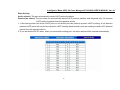
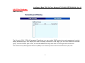
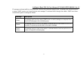
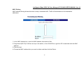
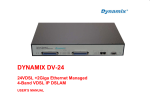
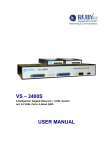
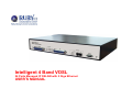
Intelligent 4 Band VDSL
24 Ports Managed IP DSLAM with 2 Giga Ethernet
USER’S MANUAL
Intelligent 4 Band VDSL 24 Ports Managed IP DSLAM USER’S MANUAL Ver. A.1
Copyright
Copyright © 2007 All rights reserved.
Trademarks
Other brand and product names are registered trademarks or trademarks of their respective holders.
Legal Disclaimer
The information given in this document shall in no event be regarded as a guarantee of conditions or characteristics. With respect to any examples or hints
given herein, any typical values stated herein and/or any information regarding the application of the device, we hereby disclaims any and all warranties and
liabilities of any kind, including without limitation warranties of non-infringement of intellectual property rights of any third party.
Statement of Conditions
In the interest of improving internal design, operational function, and/or reliability, we reserve the right to make changes to the products described in this
document without notice. We do not assume any liability that may occur due to the use or application of the product(s) or circuit layout(s) described herein.
Maximum signal rate derived form IEEE Standard specifications. Actual data throughput will vary. Network conditions and environmental factors, including
volume of network traffic, building materials and construction, and network overhead lower actual data throughput rate.
1
Intelligent 4 Band VDSL 24 Ports Managed IP DSLAM USER’S MANUAL Ver. A.1
VDSL Solution
The VDSL networking solution delivers Cost-effective, high-performance broadband access to multi-unit buildings (hotels,
apartment, and multi-tenant unit office buildings) and enterprise campus environments such as manufactories, educational
campuses, and medical facilities. VDSL technology dramatically extends Ethernet over existing Category 1/2/3 wiring at speeds of
5/15/25 Mbps (full duplex) and distances up to 1700/1100/600 meters. The VDSL technology delivers broadband service on the
same lines as Plain Old Telephone Service (POTS), digital telephone, and ISDN system. In addition, VDSL supports modes
compatible with symmetric digital subscriber line, allowing service providers to provision VDSL to buildings where broadband
services already exist.
The VDSL solution includes (24 ports VDSL IP DSLAM), and VDSL Modem for Customer Premise Equipment (CPE) device.
The VDSL solution delivers everything needed to quickly deploy an Ethernet-based network with the performance required to
deliver high-speed Internet access at much greater distances and drive services like IP telephony and audio/video streaming. With
this technology, a broad range of customers can benefit from lower operating Costs and rapid deployment. The VDSL solution
provides multicast, Layer 2 quality of service (QoS), Link Aggregation (LACP) dynamic trunking groups, security, GVRP, IGMP for
VOD (Video on demand) and SNMP RMON management and Web-based Switch network management.
The 24 ports VDSL IP DSLAM is a bridge between external Internet backbone through a router for IP sharing and the building 110D
telephone rack or telephone box. It utilizes the available telephone wire to enable high-speed Internet access to building’s
residents.
2
Intelligent 4 Band VDSL 24 Ports Managed IP DSLAM USER’S MANUAL Ver. A.1
The 24 ports VDSL IP DSLAM uses the phone line networking technology endorsed by the VDSL (Very High Data Rate DSL), and
the 24 ports VDSL IP DSLAM utilizes the already existing telephone wire to deliver 5/15/25 Mbps Internet access on each RJ-21
port.
This gives users a low-Cost, end-to-end solution and eliminates the need to train installation teams on multiple systems.
3
Intelligent 4 Band VDSL 24 Ports Managed IP DSLAM USER’S MANUAL Ver. A.1
24 Ports VDSL + 2 Giga Ethernet
The 24 ports VDSL IP DSLAM provide 1 x RJ-21 (24 x POTS Ports) with splitter on board, 1 x RJ-21 (24 x VDSL Ports) and 2 x
10/100/1000Mbps auto-sensing RJ-45. The 24 ports VDSL IP DSLAM is a rack-unit (1.5RU) high, 299 mm deep. It is a standard
19” Rack mounted size. The 24 ports VDSL IP DSLAM delivers dedicated bandwidth per port at rates up to 25 Mbps. VDSL
transmissions coexist with POTS and ISDN, and can be compatible with ADSL/HomePNA traffic in the same building. This VDSL
IP DSLAM can be configured on a per-switch basis to support the following modes:
5/10/15 Mbps symmetrical rate (up to 1700 / 1100 / 600 meters) and speed rate control from 100k up to 25Mbps. The 24 ports
VDSL IP DSLAM and VDSL Modem provide fast and easy connectivity into building patch panels with RJ-21 connector. The
10/100/1000 Ethernet ports can be used to connect servers, Ethernet switches. These connectivity options provide multiple
price/performance options to meet building and budget requirements.
4
Intelligent 4 Band VDSL 24 Ports Managed IP DSLAM USER’S MANUAL Ver. A.1
The 24 ports VDSL IP DSLAM provides the important features necessary for robust networks:
• Quality of Service: Supports 802.1p QoS. Provides high-and low-priority queuing on a per-port basis.
• Supports IGMP: Snooping by 512 IP multicast table for VOD (Video on demand) and Video Conference and Internet games
application.
• Scalability: Supports bandwidth control from 100k to 5/15/25 Mbps symmetric performance over single-pair wiring. Fast
Ethernet Channel port aggregation.
• Security: 802.1Q Tag base and port-based virtual local-area network (VLAN) support. Private VLAN access, assuring port
security without requiring a VLAN per port, and also Supports MAC filtering to Lock MAC address and 802.1V
Protocol V-Lan
• In band Management: 24 ports VDSL IP DSLAM provides a console port for setup IP or other function
• Out of Band Management: 24 ports VDSL IP DSLAM support remote control by Telnet and Web-based Management
easy-to-use configuration and ongoing monitoring. This software is embedded in the 24 ports
VDSL IP DSLAM and delivers remote, intuitive management of 24 ports VDSL IP DSLAM and
connected VDSL CPE devices through a single IP address. The 24 ports VDSL IP DSLAM is
easy-to-configured and deployed, and offering a compelling option in terms of cost,
performance, scalability and services compared to traditional ATM-based xDSL solutions.
•
•
•
•
•
•
Speed Rate Control: 24 ports VDSL IP DSLAM supports speed rate control function, from 100k to 5/15/25Mbps.
IEEE-802.1x: port base network access control, this function for wireless users connecting Authentication
Spanning tree: Supports IEEE802.1d for MAC bridge and link redundant.
DHCP Client: Dynamic Host Configuration Protocol (DHCP) for auto configure management IP.
TFTP Protocol: Trivial File Transfer Protocol (TFTP) for new version firmware remote upgraded
SNR indication: Signal to Noise Ratio (SNR) for check phone wiring quality and cross talk for offering wiring information to
engineer.
5
Intelligent 4 Band VDSL 24 Ports Managed IP DSLAM USER’S MANUAL Ver. A.1
• FAN & Temperature Monitor: This is a monitoring function for the cooler FAN speed and inner temperature status, if
the FAN stops or the temperature is over 70°C, the alarm trap will be sent via SNMP.
• SNMP MIB Supports: RFC-1213 MIBII, RFC-1493 Bridge MIB, RFC-1643 Ether like MIB, RFC-1757 RMON MIB / groups
1,2,3,9, Enterprise MIB.
• Giga port auto link supports: This function can be auto sensing client interface media with Copper or fiber optic and link one
and supports hot swap.
• Alarm: In order to make sure the system is working normally, the 24 ports VDSL IP DSLAM provides Fan and Temperature
monitor and management, you can see through WEB or Telnet which shows the internal temperature and fan speed, if
the temperature exceeds 70°C or the fan stops working, the VDSL IP DSLAM will send a SNMP trap to inform the
Trap management server.
• Hacker prevention: To avoid hacker to enter management system through client side (CPE), the 24 ports VDSL IP DSLAM
will filter system IP from client side.
• Supports multiple web browsers: IE, Mozilla & Netscape under Windows O/S Mozilla & Netscape under Linux O/S
6
Intelligent 4 Band VDSL 24 Ports Managed IP DSLAM USER’S MANUAL Ver. A.1
Safety Warnings
For your safety, be sure to read and follow all warning notices and instructions before device use.
• DO NOT open the device or unit. Opening or removing covers can expose you to dangerous high voltage points or other risks.
ONLY qualified service personnel can service the device. Please contact your vendor for further information.
• Use ONLY the dedicated power supply for your device. Connect the power cord or power adaptor to the right supply voltage
(110V AC in North America or 230V AC in Europe).
• DO NOT use the device if the power supply is damaged as it might cause electrocution. If the power supply is damaged, remove
it from the power outlet. DO NOT attempt to repair the power supply. Contact your local vendor to order a new power supply.
• Place connecting cables carefully so that no one will step on them or stumble over them. DO NOT allow anything to rest on the
power cord and do NOT locate the product where anyone can work on the power cord.
• DO NOT install nor use your device during a thunderstorm. There may be a remote risk of electric shock from lightning.
• DO NOT expose your device to dampness, dust or corrosive liquids.
• DO NOT use this product near water, for example, in a wet basement or near a swimming pool.
• Connect ONLY suitable accessories to the device. Make sure to connect the cables to the correct ports.
• DO NOT obstruct the device ventilation slots, as insufficient airflow may harm your device.
• DO NOT store things on the device.
• DO NOT use the device outside, and make sure all the connections are indoors. There may be a remote risk of electric shock
from lightning.
• Be careful when unplugging the power, because the transformer may be very hot.
• Keep the device and all its parts and accessories out of children’s reach.
• Clean the device using a soft and dry cloth rather than liquid or atomizers. Power off the equipment before cleansing it.
• This product is recyclable. Dispose of it properly.
7
Intelligent 4 Band VDSL 24 Ports Managed IP DSLAM USER’S MANUAL Ver. A.1
Contents
Copyright ...............................................................................................................1
VDSL Solution .......................................................................................................2
24 Ports VDSL + 2 Giga Ethernet.........................................................................4
Safety Warnings....................................................................................................7
Contents ................................................................................................................8
1. Unpacking Information .....................................................................................11
Check List.......................................................................................................11
2. Installing the IP DSLAM....................................................................................12
Hardware Installation.....................................................................................12
Pre-installation Requirements ......................................................................12
General Rules.................................................................................................13
Connecting the IP DSLAM.............................................................................13
Connecting Ethernet Port .............................................................................14
Connecting VDSL Ports ................................................................................14
3. Hardware Description .......................................................................................16
Front Panel .....................................................................................................16
Front Indicators..............................................................................................17
Rear Panel ......................................................................................................18
4. Management Configuration..............................................................................19
4.1 In-Band Management...............................................................................19
8
Intelligent 4 Band VDSL 24 Ports Managed IP DSLAM USER’S MANUAL Ver. A.1
4.2 Remote Network Management................................................................24
4.3 Web Basic Management..........................................................................26
4.3.1 Port Status......................................................................................26
4.3.2 Port Statistics.................................................................................27
4.3.3 TFTP Update...................................................................................28
4.3.4 TFTP Backup..................................................................................29
4.4 Web Administrator Management ............................................................30
4.4.1 IP Address ......................................................................................30
4.4.2 Switch Settings ..............................................................................31
4.4.3 Port Location..................................................................................34
4.4.4 Port Controls..................................................................................35
4.4.5 Trunking .........................................................................................36
4.4.6 Filter Database ...............................................................................40
4.4.7 Vlan Config.....................................................................................43
4.4.8 Spanning Tree................................................................................50
4.4.9 Port Sniffer .....................................................................................53
4.4.10 Snmp.............................................................................................54
4.4.11 Security Manager .........................................................................56
4.4.12 802.1X Config ...............................................................................57
4.4.13 Modem Location ..........................................................................59
4.4.14 Reset System ...............................................................................60
4.4.15 Reboot ..........................................................................................60
5. Applications ......................................................................................................61
9
Intelligent 4 Band VDSL 24 Ports Managed IP DSLAM USER’S MANUAL Ver. A.1
Appendix A: RJ-21 Telco ports distribution .......................................................64
Appendix B: VDSL Spectrum...............................................................................66
Key Features & Benefits................................................................................67
Product Specification ....................................................................................68
Appendix D: Example of VLAN Setting ...............................................................69
Appendix E: Troubleshooting..............................................................................76
Diagnosing VDSL Indicators.........................................................................76
System Diagnostics.......................................................................................78
Appendix F: Compliance and Safety Information .......................................80
Warranty ................................................................................................................83
10
Intelligent 4 Band VDSL 24 Ports Managed IP DSLAM USER’S MANUAL Ver. A.1
1. Unpacking Information
Check List
Carefully unpack the package and check its contents against the checklist.
Package Contents
•
•
•
•
•
•
•
24 ports VDSL IP DSLAM
User Manual CD
AC Power cord
2x Rack Mounting Brackets
8x Screws for Brackets
4x Plastic feet
2x 1.5m RJ-21 male-to-male Telco connector wire (Option Parts)
Please inform your dealer immediately for any missing, or damaged parts.
If possible, retain the carton, including the original packing materials.
Use them to repack the unit in case there is a need to return for repair.
11
Intelligent 4 Band VDSL 24 Ports Managed IP DSLAM USER’S MANUAL Ver. A.1
2. Installing the IP DSLAM
Hardware Installation
This chapter describes how to install the 24 ports VDSL IP DSLAM to establish network connection. You may install
the IP DSLAM on any level surface (table, shelf, 19 inch rack or wall mounting). However, please take note of the
following minimum site requirements before you begin.
Pre-installation Requirements
Before you start actual hardware installation, make sure you can provide the right operating environment, including
power requirements, sufficient physical space, and proximity to other network devices that are to be connected. Verify
the following installation requirement:
Verify the following installation requirements:
•
Power requirements: AC 100V to 240 V at 50 to 60 Hz.
The Switch power supply automatically adjusts to the input voltage level.
Power Consumption: 38.5 W
•
The IP DSLAM should be located in a cool dry place, with at least 10cm/4in of space at the front and
back for ventilation.
•
Place the IP DSLAM out of direct sunlight, and away from heat sources or areas with a high amount of
electromagnetic interference.
•
Check if network cables and connectors needed for installation are available
12
Intelligent 4 Band VDSL 24 Ports Managed IP DSLAM USER’S MANUAL Ver. A.1
General Rules
Before making any connections to the IP DSLAM, note the following rules:
• Ethernet Port (RJ-45)
All network connections to the IP DSLAM Ethernet port must be made using Category 5 UTP for 100Mbps,
Category 3, 4 UTP for 10Mbps.
No more than 100 meters of cabling may be use between the IP DSLAM or HUB and an end node.
• VDSL Port (RJ-21)
All Home network connections to VDSL
1 X RJ-21 Cable (Male to Male) Using Pin 1 ~ 24, 26 ~ 49
RJ-21 Pin25 & 50 are not used.
Connecting the IP DSLAM
The 24-port VDSL IP DSLAM has 2 x GIGA Ethernet supporting full or half-duplex operation. The transmission mode
is using auto-negotiation. Therefore, the devices attached to these ports must support auto-negotiation unless they
will always operate at half duplex. If transmissions must run at full duplex, but the attached device does not support
auto-negotiation, then you should upgrade this device to a newer version that supports auto-negotiation.
Use “25” port connect to devices such as server, bridge or router. You can also cascade to another compatible MUX
or hub by connecting the 26 port to the other device.
13
Intelligent 4 Band VDSL 24 Ports Managed IP DSLAM USER’S MANUAL Ver. A.1
Connecting Ethernet Port
Ethernet Port “25” and “26” support auto MDI/MDIX.
You can connect the “25 or 26” port on the IP DSLAM to any device that uses a standard network interface such as a
Cable modem, ADSL modem, Ethernet Switch, workstation or server, or also to a network interconnection device
such as a bridge or router (depending on the port type implemented).
Prepare straight through (or cross over) shielded or unshielded twisted-pair cables with RJ-45 plugs on both ends.
Use 100Ω Category 5 cable for connections. Connect one end of the cable to “25” port of the IP DSLAM, and the
other end to a standard RJ-45 station port on cable modem, ADSL router, wireless bridge, etc. When inserting an
RJ-45 plug, be sure the tab on the plug clicks into position to ensure that it is properly seated.
Notes: Make sure the length of twisted-pair cable is not over 100 meters (328 feet).
Connecting VDSL Ports
1. Prepare the network devices you wish to connect. Make sure you have installed suitable VDSL Modem before
making a connection to any of the IP DSLAM (1-24) station ports. You also need to prepare one 18 ~ 26 gauge
twisted pair phone Line wiring with RJ-21 plugs at both ends.
2. Connect one end of the cable to the RJ-21 port of the Home Access network adapter, and the other end to any
available (1~24) station port on the VDSL. Every port supports 5/15/25 Mbps connections. When inserting an
RJ-21 plug, be sure the tab on the plug clicks into position to ensure that it is properly seated.
• Instead, use only twisted-pair cables with RJ-45 connectors that conform the FCC standards.
14
Intelligent 4 Band VDSL 24 Ports Managed IP DSLAM USER’S MANUAL Ver. A.1
Notes:
1. Be sure each twisted-pair cable (RJ-45) does not exceed 100 meters (333 feet).
2. RJ-11 port use 18 ~ 26 gauge phone wiring, we do not recommend 28 gauge or above.
3. We advise using Category 5 cable for Cable Modem or Router connections to avoid any confusion or
inconvenience in the future when you upgrade attached to high bandwidth devices.
15
Intelligent 4 Band VDSL 24 Ports Managed IP DSLAM USER’S MANUAL Ver. A.1
3. Hardware Description
This section describes the important parts of the 24 ports IP DSLAM. It features the front indicators and rear connectors.
Front Panel
The following figure shows the front panel.
Front Panel
The 24 ports VDSL IP DSLAM has embedded Splitter between every VDSL side and POTS side. It permits you can
deliver broadband service on the same lines as Plain Old Telephone Service (POTS), ISDN traffic and VDSL Signal.
Several LED indicators for monitoring the device itself, and the network status. At a quick glance of the front panel, the
user would be knew if the product is receiving power; if it is monitoring another IP DSLAM or other devices; or if a problem
exists on the network.
The 24-port VDSL IP DSLAM provides one 10/100/1000Mbps auto-sensing RJ-45 Ethernet port as Ethernet expansion
port and one 10/100/1000 RJ-45 trunk port with auto link function.
16
Intelligent 4 Band VDSL 24 Ports Managed IP DSLAM USER’S MANUAL Ver. A.1
Front Indicators
The 24 ports IP DSLAM has many LED indicators. The following Table shows the description.
LED Indicators Description and Operation
LEDs
Color
Status
Descriptions
PWR
(Power LED)
Green
On
The device is receiving the power and functioning properly.
Off
The device is not ready or has malfunctioned.
POST
Green
(Power On Self Test LED)
On
The device is receiving the power and functioning properly.
Off
The device is not ready or has malfunctioned.
LINK STATUS
(24 Ports LED)
On
Port is in good linkage.
Green
Off
The VDSL connection is down.
10/100/1000ACT
(GIGA PORT LED)
On
GIGA Port is in one of the speed with good linkage.
Green
Off
The GIGA Port connection is down.
17
Intelligent 4 Band VDSL 24 Ports Managed IP DSLAM USER’S MANUAL Ver. A.1
Rear Panel
The following figure shows the rear connectors.
Rear connectors
The power cord should be plugged into AC Power Socket. It accepts AC power from 100 to 240 voltages.
18
Intelligent 4 Band VDSL 24 Ports Managed IP DSLAM USER’S MANUAL Ver. A.1
4. Management Configuration
4.1 In-Band Management
Console Port (RS-232) Configuration (Change IP Address via Hyper-Terminal)
1. Connect IP DSLAM with PC/Laptop’s RS-232 port, using “Hyper-Terminal” in the Windows™ system.
Set “Bits per second” at 9600 to the content window.
Set “Flow control” at None
19
Intelligent 4 Band VDSL 24 Ports Managed IP DSLAM USER’S MANUAL Ver. A.1
2. After login window show on the screen, it will ask for Login Name and Password.
Login Name: admin, Password: 123
Main Manual window will show on the screen as the following:
Operation:
Arrow/Tab/Backspace = Move light bar to select Item
Enter = Select Item
20
Intelligent 4 Band VDSL 24 Ports Managed IP DSLAM USER’S MANUAL Ver. A.1
3. Set IP Address:
(1) Select “Switch Static Configuration” to enter the Switch Configuration page.
(2) Select “Administration Configuration” to enter the Device Configuration page
21
Intelligent 4 Band VDSL 24 Ports Managed IP DSLAM USER’S MANUAL Ver. A.1
(3) Select “IP Configuration” to enter the IP configuration page
22
Intelligent 4 Band VDSL 24 Ports Managed IP DSLAM USER’S MANUAL Ver. A.1
(4) In the “IP Configuration”, it allows user to setup the DHCP, IP Address, Subnet Mask and Gateway.
a. Select <Edit> to Change IP address, Subnet Mask and Gateway
b. Select <Save> to save the configuration and go back to System Configuration page
c. Select <Quit> to go back to the previous menu
d. Use CTRL+A to go back to the last action
23
Intelligent 4 Band VDSL 24 Ports Managed IP DSLAM USER’S MANUAL Ver. A.1
4.2 Remote Network Management
IP Setting
It must assign an IP for the IP DSLAM via the console port (RS-232 Port) before users configure the VDSL IP DSLAM
via Telnet and Web. Or users can modify the PC/Laptop’s IP domain same as the VDSL IP DSLAM and use the
manufacturer default IP to configure the VDSL IP DSLAM.
1. Remote control by “Telnet”
To enter Telnet, type the IP address of the VDSL switch to connect management system. And type User name and
password.
Default User Name: admin
Default Password: 123
Note:
2. For the security reason, the device limits the numbers of user login via Telnet and Console port. User can’t login
the device via Telnet and Console port at the same time.
User must log-out to leave after finish configures the device via Consol port, or the user can’t login via Telnet.
3. WEB management doesn’t limit the numbers of user login.
24
Intelligent 4 Band VDSL 24 Ports Managed IP DSLAM USER’S MANUAL Ver. A.1
2. Network control by “WEB”
The 24 ports VDSL IP DSLAM provides WEB UI to manage the device. The default configurations are as follows:
Default IP Address: 192.168.16.250
Subnet Mask: 255.255.255.0
Default Gateway: 192.168.16.1
User Name: admin
Password: 123
User can modify the IP Configuration instead of the manufacturer default settings via Console port before login the IP
DSLAM via WEB UI. User can use the Default IP Address or User’s defining IP Address get into the Web UI, and it
will ask for user name and password as above.
25
Intelligent 4 Band VDSL 24 Ports Managed IP DSLAM USER’S MANUAL Ver. A.1
4.3 Web Basic Management
4.3.1 Port Status
This page can see every port status that depended on user setting and the negotiation result.
1. State: Display port statuses disable or enable. “Unlink” will be treated as “off”.
2. Link: Down is “No Link”, UP is “Link”.
3. SNR: (Sign to Noise Ratio) The SNR can use as an indication of the quality of the Link. If SNR Value>25, it means
connection in Good Link status.
4. Speed: Port 1-24 are 5/15/25Mbps VDSL, Port 25-26 are 10/100/1000Mbps.
5. Duplex: Display full-duplex or half-duplex mode.
6. Flow Control: Full: Display the flow control status is “enable” or “disable” in full mode.
Half: Display the backpressure is “enable” or “disable” in half mode
7. Rate Control: Display the rate control setting.
Ingr: Display the Port effective ingress rate of user setting.
Egr: Display the Port effective egress rate of user setting.
26
Intelligent 4 Band VDSL 24 Ports Managed IP DSLAM USER’S MANUAL Ver. A.1
4.3.2 Port Statistics
The following information provides a view of the current status of the unit.
Press “Reset” button to clean all counts.
27
Intelligent 4 Band VDSL 24 Ports Managed IP DSLAM USER’S MANUAL Ver. A.1
4.3.3 TFTP Update
The following menu functions allow user update the firmware and remote boot device:
1. Install TFTP Turbo98 and execution.
2. Copy firmware update version image.bin to TFTP Turbo98 directory.
3. In web management select administrator—TFTP update firmware.
4. Download new image.bin file then in web management press <update firmware>.
5. After update finished, press <reboot> to restart switch.
28
Intelligent 4 Band VDSL 24 Ports Managed IP DSLAM USER’S MANUAL Ver. A.1
4.3.4 TFTP Backup
TFTP Restore Configuration
Use this function to set TFTP server address. User can restore EEPROM value from here, but before the IP DSLAM
restore the flash image file, the image file must store in TFTP server.
TFTP Backup Configuration
Use this function to set TFTP server IP address. User can save current EEPROM value from here, then go to the
TFTP restore configuration page to restore the EEPROM value.
29
Intelligent 4 Band VDSL 24 Ports Managed IP DSLAM USER’S MANUAL Ver. A.1
4.4 Web Administrator Management
4.4.1 IP Address
1. User can configure the IP Settings and fill the new values in here.
30
Intelligent 4 Band VDSL 24 Ports Managed IP DSLAM USER’S MANUAL Ver. A.1
4.4.2 Switch Settings
Basic
Description: Display the name of device type.
MAC Address: The unique hardware address assigned by manufacturer (default)
Firmware Version: Display the device’s Firmware version.
Hardware version: Display the device’s Hardware version.
Default config value version: Display write to default EEPROM value table version.
GIGA Ports Info
Display information of Giga Ports.
31
Intelligent 4 Band VDSL 24 Ports Managed IP DSLAM USER’S MANUAL Ver. A.1
Advanced
Miscellaneous Settings
Mac Address Age-out Time: Setting the time for inactive MAC address remains in the Switch’s address table.
Max bridge transit delay bound control: Limit the packets queuing time in IP DSLAM. If this function is enable, the
packets queued exceed will be dropped.
Broadcast Storm Filter: To configure broadcast storm control, enable it and set the upper threshold for individual
ports. The threshold is the percentage of the port's total bandwidth used by broadcast traffic.
When broadcast traffic for a port rises above the threshold you set, broadcast storm control
becomes active.
32
Intelligent 4 Band VDSL 24 Ports Managed IP DSLAM USER’S MANUAL Ver. A.1
Priority Queue Service settings
First Come First Service: The sequence of packets sent is depend on arrive order.
All High before Low: The high priority packets sent before low priority packets.
WRR: Weighted Round Robin. Select the preference given to packets in the switch's high-priority queue.
These options represent the number of high priority packets sent before one low priority packet is sent. For example,
5 High: 2 Low means that the switch sends 5 high priority packets before sending 2 low priority packets.
QoS Policy: High Priority Levels: 0~7 priority level can map to high or low queue.
Collisions Retry Forever: Enable or Disable Collisions Retry Forever.
Hash Algorithm: Select in CRC-Hash mode or DirectMap mode
802.1x Protocol: Enable or disable 802.1x Protocol.
33
Intelligent 4 Band VDSL 24 Ports Managed IP DSLAM USER’S MANUAL Ver. A.1
4.4.3 Port Location
This page allows for the identification of the location of each Remote Modem. In the text box next to a port, type the
location of the Remote Modem for that port. The field is limited to alphanumeric characters and hyphen, and will
accept a maximum 10 characters.
34
Intelligent 4 Band VDSL 24 Ports Managed IP DSLAM USER’S MANUAL Ver. A.1
4.4.4 Port Controls
This section shows you how to change every port status and speed mode.
1. State: User can disable or enable this port control.
2. Negotiation: User can set auto negotiation mode is Auto, Force of per port, Nway (specify the speed/duplex on
this port and enable auto-negotiation).
3. Speed: User can set 5Mbps / 10Mbps / 15Mbps for port 1 ~ 24.
1000Mbps, 100Mbps or 10Mbps speed for Port25 ~ Port26.
4. Duplex: User can set full-duplex or half-duplex mode of per port.
5. Flows control: Full: User can set flow control function is enable or disable in full mode.
Half: User can set backpressure is enable or disable in half mode.
6. Rate Control: 24 ports VDSL IP DSLAM, port 1 ~ port 24, supports by-port ingress and egress rate control. For
example, assume Port 1 is 10Mbps, users can set it’s effective egress rate is 1Mbps, ingress rate is
500Kbps. IP DSLAM will be performed flow control or backpressure to confine the ingress rate to
meet the specified rate.
Ingress: The valid range is 0 ~ 100 (100 = 10Mbps). The unit is 100K. 0: disable rate control.
Egress: The valid range is 0 ~ 100 (100 = 10Mbps). The unit is 100K. 0: disable rate control.
35
Intelligent 4 Band VDSL 24 Ports Managed IP DSLAM USER’S MANUAL Ver. A.1
4.4.5 Trunking
The Link Aggregation Control Protocol (LACP) provides a standardized means for exchanging information between
Partner Systems on a link to allow their Link Aggregation Control instances to reach agreement on the identity of the
Link Aggregation Group to which the link belongs, move the link to that Link Aggregation Group, and enable its
transmission and reception functions in an orderly manner. In conclusion, Link aggregation lets you group up to eight
consecutive ports into a single dedicated connection. This feature can expand bandwidth to a device on the network.
LACP operation requires full-duplex mode, more detail information refers to IEEE802.3ad.
36
Intelligent 4 Band VDSL 24 Ports Managed IP DSLAM USER’S MANUAL Ver. A.1
Aggregator setting
System Priority: A value used to identify the active LACP. The switch with the lowest value has the highest priority
and is selected as the active LACP.
1. Group ID: There are seven trunk groups to provide configure. Choose the "group id" and click "Get".
2. LACP: If enable, the group is LACP static trunking group. If disable, the group is local static trunking group. All
ports support LACP dynamic trunking group. If connecting to the device that also supports LACP, the LACP
dynamic trunking group will be created automatically.
3. Work ports: Allow max four ports can be aggregated at the same time. If LACP static trunking group, the exceed
ports is standby and able to aggregate if work ports fail. If local static trunking group, the number
must be as same as the group member ports.
4. Select the ports to join the trunking group. Allow max four ports can be aggregated at the same time.
5. If LACP enable, you can configure LACP Active/Passive status in each ports on State Activity page.
6. Click Apply.
37
Intelligent 4 Band VDSL 24 Ports Managed IP DSLAM USER’S MANUAL Ver. A.1
Aggregator Information
When you are setting LACP aggregator, you can see relation information in here.
1. This page is no group active. LACP don’t working.
2. This page is Static Trunking group.
38
Intelligent 4 Band VDSL 24 Ports Managed IP DSLAM USER’S MANUAL Ver. A.1
State Activity
Active (select): The port automatically sends LACP protocol packets.
Passive (no select): The port does not automatically sends LACP protocol packets, and responds only if it receives
LACP protocol packets from the opposite device.
1. A link having either two active LACP ports or one active port can perform dynamic LACP trunking. A link has two
passive LACP ports will not perform dynamic LACP trunking because both ports are waiting for and LACP protocol
packet from the opposite device.
2. If you are active LACP’s actor, when you are select trunking port, the active status will be created automatically.
39
Intelligent 4 Band VDSL 24 Ports Managed IP DSLAM USER’S MANUAL Ver. A.1
4.4.6 Filter Database
IGMP Snooping
The 24 ports VDSL IP DSLAM supports IP multicast, you can enable IGMP protocol on web management’s switch
setting advanced page, then display the IGMP snooping information in this page, you can view difference multicast
group, VID and member port in here, IP multicast addresses range from 224.0.0.0 through 239.255.255.255.
The Internet Group Management Protocol (IGMP) is an internal protocol of the Internet Protocol (IP) suite.
40
Intelligent 4 Band VDSL 24 Ports Managed IP DSLAM USER’S MANUAL Ver. A.1
IP manages multicast traffic by using switches, routers, and hosts that support IGMP. Enabling IGMP allows the ports
to detect IGMP queries and report packets and manage IP multicast traffic through the switch. IGMP have three
fundamental types of message as follows:
Message
Description
Query
A message sent from the carrier (IGMP router or switch) asking for a response from
each host belonging to the multicast group.
Report
A message sent by a host to the carrier to indicate that the host wants to be or is a
member of a given group indicated in the report message.
Leave
Group
A message sent by a host to the carrier to indicate that the host has quit to be a m
ember of a specific multicast group.
41
Intelligent 4 Band VDSL 24 Ports Managed IP DSLAM USER’S MANUAL Ver. A.1
MAC filtering
MAC address filtering allows the switch to drop unwanted traffic. Traffic is filtered based on the destination
addresses.
1. In the MAC Address box, enter the MAC address that wants to filter.
2. If tag-based (802.1Q) VLAN are set up on the switch, in the VLAN ID box, type the VID to associate with the MAC
address.
3. Click the Add.
4. Choose the MAC address that you want to delete and then click the Delete.
42
Intelligent 4 Band VDSL 24 Ports Managed IP DSLAM USER’S MANUAL Ver. A.1
4.4.7 Vlan Config
A Virtual LAN (VLAN) is a logical network grouping that limits the broadcast domain. It allows you to isolate network
traffic so only members of the VLAN receive traffic from the same VLAN members.
Basically, creating a VLAN from a switch is logically equivalent of reconnecting a group of network devices to another
Layer 2 switch. However, all the network devices are still plug into the same switch physically.
The VDSL IP DSLAM support port-based VLAN and 802.1Q (tagged-based) VLAN in web management page.
NOTE:
The device may need 50 seconds for changing VLAN Operation Mode from No VLAN to 802.1Q.
It is necessary to reboot the IP DSLAM for valid value after the VLAN mode changed every time.
43
Intelligent 4 Band VDSL 24 Ports Managed IP DSLAM USER’S MANUAL Ver. A.1
Port-based VLAN
Packets can go among only members of the same VLAN group. Note all unselected ports are treated as belonging to
another single VLAN. If the port-based VLAN enabled, the VLAN-tagging is ignored.
44
Intelligent 4 Band VDSL 24 Ports Managed IP DSLAM USER’S MANUAL Ver. A.1
1. Click Add to create a new VLAN group.
2. Enter the VLAN name, group ID and select the members for the new VLAN, then click Apply.
3. If the VLAN groups over the page’s limitation, user can use “Next Page” to view other VLAN groups.
NOTE: If the trunk groups exist, it (ex: TRK1, TRK2…) will show in select menu of ports, and user can set it in the
member of the VLAN or not.
45
Intelligent 4 Band VDSL 24 Ports Managed IP DSLAM USER’S MANUAL Ver. A.1
Tag-based VLAN (IEEE 802.1Q VLAN)
Tagged-based VLAN is an IEEE 802.1Q specification standard. Therefore, it is possible to create a VLAN across
devices from different switch venders. IEEE 802.1Q VLAN uses a technique to insert a “tag” into the Ethernet frames.
Tag contains a VLAN Identifier (VID) that indicates the VLAN numbers.
In order to an end station to send packets to different VLANs, it itself has to be either capable of tagging packets it
sends with VLAN tags or attached to a VLAN-aware bridge that is capable of classifying and tagging the packet with
different VLAN ID based on not only default PVID but also other information about the packet, such as the protocol.
46
Intelligent 4 Band VDSL 24 Ports Managed IP DSLAM USER’S MANUAL Ver. A.1
802.1Q VLAN
This page, user can create Tag-based VLAN, and enable or disable GVRP protocol.
There are 256 VLAN groups to provide configure. Enable 802.1Q VLAN, the all ports on the switch belong to default
VLAN, VID is 1. The default VLAN can’t be deleted.
GVRP (GARP [Generic Attribute Registration Protocol] VLAN Registration Protocol)
GVRP allows automatic VLAN configuration between the switch and nodes. If the 24 ports VDSL IP DSLAM is
connected to a device with GVRP enabled, you can send a GVRP request using the VID of a VLAN defined on the 24
ports VDSL IP DSLAM, the 24 ports VDSL IP DSLAM will automatically add that device to the existing VLAN.
47
Intelligent 4 Band VDSL 24 Ports Managed IP DSLAM USER’S MANUAL Ver. A.1
Port VID (PVID)
Set the port VLAN ID that will be assigned to untagged traffic on a given port. This feature is useful for
accommodating devices that you want to participate in the VLAN but that don’t support tagging. VDSL SWITCH each
port allows user to set one PVID, the range is 1~4094, default PVID is 1. The PVID must as same as the VLAN ID
that the port belong to VLAN group, or the untagged traffic will be dropped.
The 24-ports VDSL IP DSLAM has 16 PVID ranges. PVID of Port 1 ~ Port 26 must be in the same range.
Num.
PVID Range
Num.
PVID Range
Num.
PVID Range
Num.
PVID Range
1
1~255
5
1024~1279
9
2048~2303
13
3072~3327
2
256~511
6
1280~1535
10
2304~2559
14
3328~3583
3
512~767
7
1536~1791
11
2560~2815
15
3584~3839
4
768~1023
8
1792~2047
12
2816~3071
16
3840~4094
48
Intelligent 4 Band VDSL 24 Ports Managed IP DSLAM USER’S MANUAL Ver. A.1
Ingress Filtering
Ingress filtering lets frames belonging to a specific VLAN to be forwarded if the port belongs to that VLAN.
VDSL IP DSLAM has two ingress filtering rule as follows:
Ingress Filtering Rule 1: Forward only packets with VID matching this port's configured VID.
Ingress Filtering Rule 2: Drop Untagged Frame.
49
Intelligent 4 Band VDSL 24 Ports Managed IP DSLAM USER’S MANUAL Ver. A.1
4.4.8 Spanning Tree
The Spanning-Tree Protocol (STP) is a standardized method (IEEE 802.1D) for avoiding loops in switched networks.
When STP enabled, to ensure that only one path at a time is active between any two nodes on the network.
You can enable Spanning-Tree Protocol on web management’s switch setting advanced item, select enable
Spanning-Tree protocol. We are recommended that you enable STP on all 24 ports VDSL IP DSLAM to ensure a
single active path on the network.
You can view spanning tree information about the Root Bridge.
You can view spanning tree status about the switch as the following screen.
50
Intelligent 4 Band VDSL 24 Ports Managed IP DSLAM USER’S MANUAL Ver. A.1
You can set new value for STP parameter
Parameter
Description
Priority
You can change priority value, A value used to identify the root bridge. The bridge
with the lowest value has the highest priority and is selected as the root. Enter a
number 1 through 65535.
Max Age
You can change Max Age value, The number of seconds a bridge waits without
receiving Spanning-Tree Protocol configuration messages before attempting a
reconfiguration. Enter a number 6 through 40.
Hello Time
You can change Hello time value, the number of seconds between the
transmissions of Spanning-Tree Protocol configuration messages. Enter a
number 1 through 10.
Forward
Delay time
You can change forward delay time, The number of seconds a port waits before
changing from its Spanning-Tree Protocol learning and listening states to the
forwarding state. Enter a number 4 through 30.
51
Intelligent 4 Band VDSL 24 Ports Managed IP DSLAM USER’S MANUAL Ver. A.1
The following parameter can be configured on each port
Parameter
Description
Port Priority
Define the priority of each port, the rage is from 0 to 255, the lower number has
the higher priority. Default Value is 128.
Path Cost
Specifies the Path Cost of the port that switch uses to determine which port are
the forwarding ports the lowest number is forwarding ports, the rage is from 1 to
65535 and default value base on IEEE802.1D
10Mb/s = 50-600
100Mb/s = 10-60
1000Mb/s = 3-10
52
Intelligent 4 Band VDSL 24 Ports Managed IP DSLAM USER’S MANUAL Ver. A.1
4.4.9 Port Sniffer
The Port Sniffer is a method for monitor traffic in switched networks. Traffic through ports can be monitored by one
specific port. That is, traffic goes in or out monitored ports will be duplicated into sniffer port.
1. Sniffer Mode: Press Space key to set sniffer mode: Disable\Rx\Tx\Both.
2. Monitoring Port: It means sniffer port can be used to see all monitor port traffic. You can connect sniffer port
to LAN analysier or netxray.
3. Monitored Port: The ports you want to monitor. All monitor port traffic will be copied to sniffer port. You can
select max 25 monitoring ports in the switch. User can choose which port wants to monitored in only one
sniffer mode.
If you want to disable the function, you must select monitor port to none.
53
Intelligent 4 Band VDSL 24 Ports Managed IP DSLAM USER’S MANUAL Ver. A.1
4.4.10 Snmp
Any Network Management running the simple Network Management Protocol (SNMP) can manage the switch,
provided the Management Information Base (MIB) is installed correctly on the management station. The SNMP is a
Protocol that governs the transfer of information between management and agent.
1. Use this page to define management stations as trap managers and to enter SNMP community strings. User can
also define a name, location, and contact person for the switch. Fill in the system options data, and then click Apply to
update the changes on this page.
Name: Enter a name to be used for the switch.
Location: Enter the location of the switch.
Contact: Enter the name of a person or organization.
54
Intelligent 4 Band VDSL 24 Ports Managed IP DSLAM USER’S MANUAL Ver. A.1
2. Community strings serve as passwords and can be entered as one of the following:
RO: Read only. Enables requests accompanied by this string to display MIB-object information.
RW: Read write. Enables requests accompanied by this string to display MIB-object information and to set MIB
objects.
3. Trap Manager
A trap manager is a management station that receives traps, the system alerts generated by the switch. If no trap
manager is defined, no traps are issued. Create a trap manager by entering the IP address of the station and a
community string.
55
Intelligent 4 Band VDSL 24 Ports Managed IP DSLAM USER’S MANUAL Ver. A.1
4.4.11 Security Manager
Using this page, user can change web management user name and password.
1. User name: Type the new user name.
2. Password: Type the new password.
3. Reconfirm password: Retype the new password.
4. Click Apply.
56
Intelligent 4 Band VDSL 24 Ports Managed IP DSLAM USER’S MANUAL Ver. A.1
4.4.12 802.1X Config
System Configuration
802.1x makes using of the physical access characteristics of IEEE802 LAN infrastructures in order to provide a
means of authenticating and authorizing devices attached to a LAN port that has point-to-point connection
characteristics, and of preventing access to that port in cases in which the authentication and authorization process
fails.
To enable 802.1x, you still to fill in the authentication server information:
• Radius Server IP Address: the IP address of the authentication server.
• Server Port: The UDP port number used by the authentication server to authenticate.
• Accounting Port: The UDP port number used by the authentication server to retrieve accounting information.
• Shared Key: A key shared between this switch and authentication server.
• NAS Identifier: A string used to identify this switch.
Per port Configuration
In this page, you can select the specific port and configure the authorization state.
Each port can select four kinds of authorization state:
• Fu: force the specific port to be unauthorized.
• Fa: force the specific port to be authorized.
• Au: the state of the specific port was determined by the outcome of the authentication.
• No: the specific port didn't support 802.1x function.
57
Intelligent 4 Band VDSL 24 Ports Managed IP DSLAM USER’S MANUAL Ver. A.1
Misc Configuration
In this page, you can change the default configuration for the 802.1x standard:
• Quiet Period: used to define periods of time during which it will not attempt to acquire a supplicant (Default
time is 60 seconds).
• Tx Period: used to determine when an EAPOL PDU is to be transmitted (Default value is 30 seconds).
• Supplicant Timeout: used to determine timeout conditions in the exchanges between the supplicant and
authentication server (Default value is 30 seconds).
• Server Timeout: used to determine timeout conditions in the exchanges between the authenticator and
authentication server (Default value is 30 seconds).
• ReAuthMax: used to determine the number of re-authentication attempts that are permitted before the specific
port becomes unauthorized (Default value is 2 times).
• ReAuth Period: used to determine a nonzero number of seconds between periodic re-authentication of the
supplications (Default value is 3600 seconds).
58
Intelligent 4 Band VDSL 24 Ports Managed IP DSLAM USER’S MANUAL Ver. A.1
4.4.13 Modem Location
This function allows for the identification of the location of each Remote Modem. In the text box to a port, type the
location of the Remote Modem for that port. The field is limited to alphanumeric characters and hyphen, and will
accept a maximum 10 characters.
59
Intelligent 4 Band VDSL 24 Ports Managed IP DSLAM USER’S MANUAL Ver. A.1
4.4.14 Reset System
Reset 24 ports VDSL IP DSLAM to default configuration.
4.4.15 Reboot
Reboot the 24 ports VDSL IP DSLAM in software reset.
60
Intelligent 4 Band VDSL 24 Ports Managed IP DSLAM USER’S MANUAL Ver. A.1
5. Applications
The VDSL provides home network architecture. Transforming an apartment into a Multiple-Family Home network area,
sharing a single internet account for multiple users with Router & Cable Modem, it can provide unlimited access time in
the internet at a reasonable low price.
Bridging Functions
The 24 ports VDSL IP DSLAM provides full transparent bridging function. It automatically connects node addresses, that
are later used to filter and forward all traffic based on the destination address. When traffic passes between devices
attached to the shared collision domain, those packets are filtered from the IP DSLAM. But when traffic must be passed
between unique segments (i.e., different ports of the IP DSLAM), a temporary link is set up between the IP DSLAM’s ports
in order to pass this traffic, 24 ports VDSL IP DSLAM (the high-speed VDSL fabric).
Transceiver function
The 24 ports VDSL IP DSLAM supports Ethernet to VDSL convert, It can be transmit or receive packet from Ethernet port
to the RJ21 port. Or VDSL port to Ethernet port.
Flexible Configuration
The 24 ports VDSL IP DSLAM is not only designed to segment your network, but also to provide a wide range of options
in the configuration of Home network connections. It can be used as a simple stand-alone IP DSLAM; or can be
connected with another IP DSLAM, Cable modem, Router, XDSL, ISDN, gateway or other network interconnection
devices in various configurations. Some of the common applications of the IP DSLAM are described in this chapter.
61
Intelligent 4 Band VDSL 24 Ports Managed IP DSLAM USER’S MANUAL Ver. A.1
Used as Apartment for Internet Access
The 24 ports VDSL IP DSLAM provides a high speed, 5/15/25Mbps transmission over existing home telephone wiring
over a single Internet account to provide simultaneous independent Internet access to multiple users.
No mater ISDN Telephone system or POTS Telephone system you are. VDSL Technology let you can use telephone
system and VDSL network system in the same time.
62
Intelligent 4 Band VDSL 24 Ports Managed IP DSLAM USER’S MANUAL Ver. A.1
Application for sharing a single internet account
If multiple users would like to share a single internet account using the 24 ports VDSL IP DSLAM, which is to be
connected to a IP sharing device, then to a xDSL or Cable Modem.
Note:
For network applications that actually require Router (e.g., Interconnecting dissimilar network types), attaching the IP
DSLAM directly to a router can significantly improve overall home networking performance.
63
Intelligent 4 Band VDSL 24 Ports Managed IP DSLAM USER’S MANUAL Ver. A.1
Appendix A: RJ-21 Telco ports distribution
RJ-21 Pin and VDSL port contrast list
VDSL 50 Pin RJ-21 Cable Connector List
Cable Characteristic = 24 AWG twist wire
1
2
3
4
5
6
7
8
9
10
11
12
13
14
15
16
17
18
19
20
21
22
23
24
24
23
22
21
20
19
18
17
16
15
14
13
12
11
10
9
8
7
6
5
4
3
2
1
&
&
&
&
&
&
&
&
&
&
&
&
&
&
&
&
&
&
&
&
&
&
&
&
49
48
47
46
45
44
43
42
41
40
39
38
37
36
35
34
33
32
31
30
29
28
27
26
Note: RJ-21 Pin25 & 50 are not used
64
Intelligent 4 Band VDSL 24 Ports Managed IP DSLAM USER’S MANUAL Ver. A.1
RJ-21 Cable Drawing (150 cm Male to Male)
65
Intelligent 4 Band VDSL 24 Ports Managed IP DSLAM USER’S MANUAL Ver. A.1
Appendix B: VDSL Spectrum
VDSL Technology – Requirements & Definitions
Spectral Allocation
• Co-exists with legacy Voice and ISDN services
Slide 5
06-April-2000
page: 5
• Co-exists with other xDSL technologies
• Programmable notch filter to avoid Radio Frequency Interference
© 2002 Infineon Technologies COM/AC
All rights reserved
VDSL Spectral Allocation
66
Intelligent 4 Band VDSL 24 Ports Managed IP DSLAM USER’S MANUAL Ver. A.1
Appendix C: Product Specification
Key Features & Benefits
• Supports bandwidth management (speed rate control) 5M/15M/25Mbps for VDSL port with long driver capable up
to 1.7/1.1/0.6Km (5666/3666/1999 feet)
• Supports GARP/GVRP IEEE-802.1p/q tagging VLAN, IEEE 802.1v protocol VLAN, port base VLAN
• Supports quality of phone wiring detected with SNR (Signal to Noise Ratio) indications
• Supports QOS IEEE-802.1p
• Supports IGMP V2 Snooping
• Supports BOOTP/DHCP Client
• Supports Bandwidth Control
• Supports LACP IEEE-802.3ad Port Trunking
• Supports IEEE 802.1d Spanning Trees
• Supports Port Mirroring (Sniffer)
• Supports Broadcast Storm filtering
• Supports 802.1x Port Based Network Access Control
• Supports Web Base and Telnet for remote management
• Supports SNMP v1 RFC-1493 Bridge MIBs, RFC-1643 Ethernet MIB, RFC-1213 MIB II, Enterprise MIB
• Supports RMON groups 1, 2, 3, 9 (RFC-1757 RMON MIB)
• Supports TFTP/XMODEM for firmware upgrade
• Supports In-Band/Out-of-Band Management
• Supports RS-232 console port for functions setup (DB-9Pin Female / 9600bps)
• Spectral compatibility with XDSL, ISDN (2B1Q/4B3T), HomePNA
67
Intelligent 4 Band VDSL 24 Ports Managed IP DSLAM USER’S MANUAL Ver. A.1
Product Specification
Standard:
IEEE802.3 standard
IEEE802.3u standard
IEEE802.3ab standard
Compliant with ETSI, ITU, ANSI standards
Interface:
2 * RJ-45 10/100/1000Mbps Ethernet port
24 * RJ-21 connector for VDSL connection
24 * RJ-21 connector for POTS/ISDN connection
Flow control:
Full duplex: IEEE 802.3x
Half duplex: Back pressure
MAC address table:
6K Entries
LED indication:
Power and POST
Link/Active/Speed/Duplex Status for Ethernet port
Link for VDSL port
VDSL Frequency Spectrum:
Transmitter: 900 KHz ~ 3.9MHz
Receiver: 4MHz & 7.9MHz
POTS/ISDN pass filter Spectrum: 0 ~ 630Khz
Operating Temperature:
0°C ~ 50°C (41°F ~ 122°F)
Storage Temperature:
-20°C ~ 65°C (-4°F ~ 149°F)
Humidity:
10 to 90% (non-condensing)
Dimensions:
434 x 299 x 66 mm
68
Intelligent 4 Band VDSL 24 Ports Managed IP DSLAM USER’S MANUAL Ver. A.1
Appendix D: Example of VLAN Setting
Example 1:
4 users join to Internet by VDSL system like following drawing, and have 7 demands.
User A connects to port 1 and join to Internet through port 26
User B connects to port 2 and join to Internet through port 26
User C connects to port 3 and join to Internet through port 26
User D connects to port 4 and join to Internet through port 26
User A isolate with Users B, C and D
User B isolate with Users A, C and D
User C and D in the same Group and isolate with Users A and B
Setup Procedure:
Setup Port VID: Assign a Port VLAN ID (1~4094) for untagged traffic on each port like following: Port 1 PVID=21, Port 2
PVID=22, Port 3, 4 PVID=23
69
Intelligent 4 Band VDSL 24 Ports Managed IP DSLAM USER’S MANUAL Ver. A.1
Add VLAN Group:
There are 256 VLAN groups available for configuration. Add a VLAN Group VID=21 member ports = port 1 & port 26
Note: Do not change the default_1 group.
70
Intelligent 4 Band VDSL 24 Ports Managed IP DSLAM USER’S MANUAL Ver. A.1
Setup VLAN Name=UserA, VID=21, select member ports 1 & 26
Select Untag or Tag Setup. Unless the device (computer or switch) which connect to port 1 or port 26 can support Tagging
VLAN, otherwise select Untag.
Add a VLAN Group Name=UserB, VID=22 member ports = port 2 & port 26
Add a VLAN Group Name=UserCD, VID=23 member ports = port 3, port 4 & port 26
71
Intelligent 4 Band VDSL 24 Ports Managed IP DSLAM USER’S MANUAL Ver. A.1
Example 2:
4 users join to Internet through 2 IP DSLAMs like the following drawing, and have 7 demands.
User A connect to port 1 of VDSL-1 and join to Internet through port 26 of VDSL-2
User B connect to port 2 of VDSL-1 and join to Internet through port 26 of VDSL-2
User C connect to port 1 of VDSL-2 and join to Internet through port 26 of VDSL-2
User D connect to port 2 of VDSL-2 and join to Internet through port 26 of VDSL-2
User A isolate with Users B, C and D
User C isolate with Users A, B and D
User B and D in the same Group and isolate with Users A and B
72
Intelligent 4 Band VDSL 24 Ports Managed IP DSLAM USER’S MANUAL Ver. A.1
Setup Procedure:
VDSL-1 SETUP:
a. Setup Port VID: Port 1 PVID=11, Port 2 PVID=12
b. Add VLAN Group:
Note: Do not change the default_1 group.
Add a VLAN Group, Group name=UserA VID=11 member ports = port 1 & port 26
Select Untag or Tag Setup for VID=11 group:
Port Number
1
26
Untag/Tag Select
Untag
Tag
Add a VLAN Group, Group name=UserBD VID=12, member ports = port 2 & port 26
Select Untag or Tag Setup for VID=12 group:
Port Number
2
26
Untag/Tag Select
Untag
Tag
73
Intelligent 4 Band VDSL 24 Ports Managed IP DSLAM USER’S MANUAL Ver. A.1
VDSL-2 SETUP:
a. Setup Port VID: Port 1 PVID=21, Port 2 PVID=12
b. Add VLAN Group:
Do not change the default_1 group.
Add a VLAN Group, Group name=UserA VID=11 member ports = port 25 & port 26
Select Untag or Tag Setup for VID=11 group:
Port Number
25
26
Untag/Tag Select
Tag
Untag
Add a VLAN Group, Group name=UserBD VID=12 member ports = port 2 & port 25 & port 26
Select Untag or Tag Setup for VID=12 group:
Port Number
2
25
26
Untag/Tag Select
Untag
Tag
Untag
74
Intelligent 4 Band VDSL 24 Ports Managed IP DSLAM USER’S MANUAL Ver. A.1
Add a VLAN Group, Group name=UserC VID=21 member ports = port 1 & port 26
Select Untag or Tag Setup for VID=21 group:
Port Number
1
26
Untag/Tag Select
Untag
Untag
75
Intelligent 4 Band VDSL 24 Ports Managed IP DSLAM USER’S MANUAL Ver. A.1
Appendix E: Troubleshooting
Diagnosing VDSL Indicators
The VDSL can be easily monitored through its comprehensive panel indicators. These indicators assist the network
manager in identifying problems of the IP DSLAM may encounter. This section describes common problems you may
encounter and possible solutions.
1. Symptom:
POWER indicator does not light up (green) after power on.
Cause:
Defective Power outlet, Power cord, Internal power supply
Solution:
Check the power outlet by plugging in another that is functioning properly. Check the power cord
with another device. If these measures fail to resolve the problem, have the unit power supply
replaced by a qualified distributor.
2. Symptom:
Link indicator does not light up (green) after making a connection.
Cause:
Network interface (ex. a network adapter card on the attached device), network cable, or switch
port is defective.
Solution:
2.1
2.2
2.3
2.4
2.5
2.6
Power off and re- power on the IP DSLAM.
Verify that the switch and attached device are powered on.
Be sure the cable is plugged into both the switch and corresponding device.
Verify that the proper cable type is used and its length does not exceed specified limits.
Check the adapter on the attached device and cable connections for possible defects.
Replace the defective adapter or cable if necessary.
76
Intelligent 4 Band VDSL 24 Ports Managed IP DSLAM USER’S MANUAL Ver. A.1
3. Symptom:
VDSL Link cannot be established
Cause:
Rusted phone wire, not standard 24 gauge phone wire, not twisted-pair phone wire, wrong speed
mode.
Solution:
Check if speed of CO and CPE is in the same speed mode else please increase interleaver depth
value to 8 or above.
Note:
Phone cable must meet Cat. 3 standard or above and without clustering, otherwise will cause more
cross talk issue to reduce DSL power driver.
77
Intelligent 4 Band VDSL 24 Ports Managed IP DSLAM USER’S MANUAL Ver. A.1
System Diagnostics
Power and Cooling Problems
If the POWER indicator does not turn on when the power cord is plugged in, you may have a problem with the power
outlet, power cord, or internal power supply as explained in the previous section. However, if the unit power is off after
running for a while, check for loose power connections, power losses or surges at the power outlet, and verify that the
fan on back of the unit is unobstructed and running prior to shutdown. If you still cannot isolate the problem, then the
internal power supply may be defective. In this case, please contact your local dealer.
Installation
Verify that all system components have been properly installed. If one or more components appear to be
malfunctioning (e.g., the power cord or network cabling), test them in an alternate environment where you are sure
that all the other components are functioning properly.
Transmission Mode
The selections of the transmission mode for the RJ-45 ports are auto-negotiation using the default method.
Therefore, if the Link signal is disrupted (e.g., by unplugging the network cable and plugging it back in again, or by
resetting the power), the port will try to re-establish communications with the attached device(auto-negotiation). If
auto-negotiation fails, then communications are set to half duplex by default. Based on this type of industry-standard
connection policy, if you are using a full-duplex device that does not support auto-negotiation, communications can be
easily lost (i.e., reset to the wrong mode) whenever the attached device is reset or experiences a power fluctuation.
The best way to resolve this problem is to upgrade these devices to version that will support auto-negotiation.
78
Intelligent 4 Band VDSL 24 Ports Managed IP DSLAM USER’S MANUAL Ver. A.1
Cabling
1. Verify that the cable type is correct. Be sure RJ-45 cable connectors are securely seated in the required ports. Use
100Ω straight-through cables for all standard connections. Use Category 5 cable for 100/1000Mbps Fast Ethernet
connections, or Category 3, 4 or 5 cables for standard 10Mbps Ethernet connections. Be sure RJ21 phone wiring,
use 18~26 gauge.
2. Make sure all devices are connected to the network. Equipment any have been unintentionally disconnected from
the network.
3. When cascading two devices using RJ-45 station ports at both ends of the cable (24 ports VDSL IP DSLAM)
supports auto MDIX), without crossover cable can be used.
Physical Configuration
If problems occur after altering the network configuration, restore the original connections, and try to track the
problem down by implementing the new changes, one step at a time. Ensure that cable distances and other physical
aspects of the installation do not exceed recommendations.
System Integrity
As a last resort verify the switch integrity with a power-on reset. Turn the power to the switch off and then on several
times. If the problem still persists and you have completed all the preceding diagnoses, then contact your dealer for
assistance.
79
Intelligent 4 Band VDSL 24 Ports Managed IP DSLAM USER’S MANUAL Ver. A.1
Appendix F: Compliance and Safety Information
FCC Radio Frequency Interference Statement
This equipment has been tested and found to comply with the limits for a computing device, pursuant to Part 15 of FCC
rules. These limits are designed to provide reasonable protection against harmful interference when the equipment is
operated in a commercial environment. This equipment generates, uses and can radiate radio frequency energy and, if
not installed and used in accordance with the instructions, may cause harmful interference to radio communications.
However, there is no guarantee that interference will not occur in a particular installation. If this equipment does cause
harmful interference to radio or television reception, which can be determined by turning the equipment off and on, the
user is encouraged to try to correct the interference by one or more of the following measures:
1.
2.
3.
4.
Reorient or relocate the receiving antenna.
Increase the separation between the equipment and receiver.
The equipment and the receiver should be connected to outlets on separate circuits.
Consult the dealer or an experienced radio/television technician for help.
Changes or modifications not expressly approved by the party responsible for compliance could void the user’s authority
to operate the equipment.
If this telephone equipment causes harm to the telephone network, the telephone company will notify you in advance that
temporary discontinuance of service may be required. But if advance notice isn’t practical, the telephone company will
notify the customer as soon as possible. Also, you will be advised of your right to file a complaint with the FCC if you
believe it is necessary.
80
Intelligent 4 Band VDSL 24 Ports Managed IP DSLAM USER’S MANUAL Ver. A.1
The telephone company may make changes in its facilities, equipment, operations or procedures that could affect the
proper functioning of your equipment. If they do, you will be notified in advance in order for you to make necessary
modifications to maintain uninterrupted service.
This equipment may not be used on coin service provided by the telephone company. Connection to party lines is subject
to state tariffs.
Important Safety Instructions
Caution: The direct plug-in wall transformer serves as the main disconnect for the product. The socket outlet shall be
installed near the product and be readily accessible.
Caution: Use only the power supply included with this product. In the event the power supply is lost or damaged: In the
United States, use only with CSA certified or UL listed Class 2 power supply, rated 5Vdc 1A or above. IN Europe,
use only with CE certified power supply, rated 5Vdc 1A or above.
Do not use this equipment near water, for example in a wet basement. Avoid using a telephone during an
electrical storm. There may be a remote risk of electrical shock from lightning.
Do not use the telephone to report a gas leak in the vicinity of the leak.
If trouble is experienced with this unit, please contact customer service at the address and phone listed below.
Do not disassemble this equipment. It does not contain any user serviceable components.
81
Intelligent 4 Band VDSL 24 Ports Managed IP DSLAM USER’S MANUAL Ver. A.1
FCC Warning
This equipment has been tested and found to comply with the limits for a Class A digital device, pursuant to Part 15 of
the FCC Rules. These limits are designed to provide reasonable protection against harmful interference when the
equipment is operated in a commercial environment. This equipment generates, uses, and can radiate radio frequency
energy and, if not installed and used in accordance with the instruction manual, may cause harmful interference to
radio communications. Operation of this equipment in a residential area is likely to cause harmful interference in which
case the user will be required to correct the interference at his own expense.
CE Mark Warning
This is a CE class A product. In a domestic environment, this product may cause radio interference in which case the
user may be required to take adequate measures.
82
Intelligent 4 Band VDSL 24 Ports Managed IP DSLAM USER’S MANUAL Ver. A.1
Warranty
The original owner that the product delivered in this package will be free from defects in material and workmanship for one
year parts after purchase.
There will be a minimal charge to replace consumable components, such as fuses, power transformers, and mechanical
cooling devices. The warranty will not apply to any products which have been subjected to any misuse, neglect or
accidental damage, or which contain defects which are in any way attributable to improper installation or to alteration or
repairs made or performed by any person not under control of the original owner.
The above warranty is in lieu of any other warranty, whether express, implied, or statutory, including but not limited to any
warranty of merchantability, fitness for a particular purpose, or any warranty arising out of any proposal, specification, or
sample. Shall not be liable for incidental or consequential damages. We neither assume nor authorize any person to
assume for it any other liability.
WARNING:
DO NOT TEAR OFF OR REMOVE THE WARRANTY STICKER AS SHOWN, OR THE WARRANTY IS VOID.
83