1
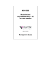
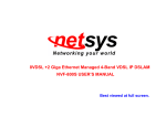
24-Port Ethernet
Management Switch
(VLAN, Trunking, QoS)
ES-5224RM
ES-5224REM
ES-5224RFM
ES-3124REM
User’s Manual
FCC COMPLIANCE STATEMENT
This equipment has been tested and found to comply with the
limits of a Class A computing devices, pursuant to Part 15 of the
FCC rules. These limits are designed to provide reasonable
protection against harmful interference.
This equipment
generates, uses and can radiate radio frequency energy and, if
not installed and used in accordance with the instructions, may
cause harmful interference to radio communications.
If you suspect this product is causing interference, turn your
computer on and off while your radio or TV is showing
interference. If the interference disappears then when you turn
the computer off and reappears when you turn the computer on,
something in the computer is causing interference.
You can try to correct the interference by one or more of the
following measures:
1. Reorient/relocate the receiving antenna.
2. Increase the separation between the equipment and receiver.
3. Connect the equipment into an outlet on a circuit difference
from that to which the receiver is connected.
4. Ensure that all expansion slots (on the back or side of the
computer) are covered. Also ensure that all metal retaining
brackets are tightly attached to the computer.
2
Content
Chapter1 Introduction
1. Introduction ......................................... 6
2. Features & Specifications ................... 8
3. Package Contents............................... 10
4. Hardware Description....................... 11
Chapter 2 Web Management Function
1. Web Management Overview............. 13
2. Port Status .......................................... 15
3.
Port Statistics ..................................... 17
4. Administrator .................................... 18
4.1
IP Address ..................................................18
4.2
Switch Settings ..........................................19
4.3
Console Port Information.........................22
4.4
Port Controls .............................................23
4.5
Trunking ....................................................25
4.6
Filter Database ..........................................28
4.7
VLAN configuration .................................31
4.8
Spanning Tree............................................36
4.9
Port Sniffer ................................................38
4.10
SNMP .........................................................39
4.11
Security Manager......................................41
3
4.12
802.1X Configuration ...............................42
4.13
TFTP Update Firmware ...........................45
4.14
Configuration Backup ..............................46
4.15
Reset System ..............................................47
4.16
Reboot ........................................................48
Chapter 3 Console-Menu Line
1. Main Menu......................................... 50
2. Switch Static Configuration.............. 51
2.1 Port Configuration..........................................52
2.2 Trunk Configuration.......................................54
2.3 VLAN Configuration ......................................55
2.4 Misc Configuration .........................................61
2.5 Administration Configuration .......................65
2.6 Port Mirroring Configuration .......................68
2.7 Priority Configuration....................................69
2.8 MAC Address Configuration .........................70
3. Protocol Related Configuration ....... 72
3.1 STP ...................................................................72
3.2 SNMP ...............................................................75
3.3 GVRP ...............................................................80
3.4 IGMP................................................................81
3.5 LACP................................................................83
3.6 802.1X...............................................................86
4. Status and Counters .......................... 89
4
4.1 Port Status........................................................90
4.2 Port Counters ..................................................91
4.3 System Information ........................................92
5. Reboot Switch .................................... 93
5.1 Default ..............................................................93
5.2 Restart ..............................................................93
6. TFTP Update Firmware.................... 94
6.1 TFTP Update Firmware .................................94
6.2 Update Configure File ....................................95
6.3 Upload Configure File ....................................97
5
Chapter 1 Introduction
1. Introduction
Congratulations on your purchase of this Fast/Gigabit Ethernet
Management Switch. This high performance management
switch provides Ethernet ports to segment network traffics,
extend Ethernet connection distance, and convert data packets
between different transmission speeds.
This switch utilizes stored-and-forward switching architecture
that filters and forwards data after the complete data packet is
received and examined to be free of errors. With one set of
status LEDs for each individual port, the switch operation status
can be easily monitored.
All the Fast Ethernet ports support both Full and Half duplex
mode which are able to provide up to 200Mbps(2000Mbps for
Gigabit Ports) of bandwidth to the connected devices, with
auto-negotiation providing the capability to connect to
100/10Mbps(1000/100/10Mbps for Gigabit ports) network
devices. It also supports backpressure and IEEE 802.3x
advanced flow control capabilities that can reduce congestion
and prevent packet loss.
And it offers advance features:
SNMP/Web-based Management: Provides a web browser
to manage and monitor the switch.
Bandwidth Control: Input and output rate control.
VLAN: Port-based and Tag-based VLAN allow you to set
virtual LANs within your network
Trunking: Reduce the bottleneck between switches
QoS: Two priority queues per port allow you to define
which port has higher priority.
802.1X: This switch supports port-based authentication
protocol, IEEE 802.1X.
6
In addition, all the ports support the MDI/MDI-X auto-detect
function. That is to say, you can connect any device (including
PC, Switch, Hub) to a port of this switch using a regular cable.
The RJ-45 port will auto-detect and auto-switch to the correct
MDI/MDI-X mode (do not need to use a specific uplink port or
cross-over cable).
7
2. Features & Specifications
Features
Complies with the IEEE802.3 Ethernet, IEEE802.3u Fast
Ethernet (IEEE802.3z, IEEE802.3ab for Gigabit switch)
Provides Store-and-Forward architecture and full wire
speed filtering and forwarding rates
10/100Mbps Ports support full/half duplex modes and
auto-negotiation
Provides two Fast Ethernet Modules option (Fast/Gigabit
Ethernet Management Switch):
♦ 100/10Mbps UTP connector (RJ-45)
♦ 100Mbps Fiber SC/ST connector (multi/single mode)
Provides two Gigabit Ethernet Modules option (Gigabit
Ethernet Management Switch only):
♦ 1000/100/10Mbps UTP connector (RJ-45)
♦ 1000Mbps Fiber SC connector (multi/single mode)
Supports flow control: back pressure for half-duplex mode,
IEEE 802.3x for full-duplex mode
Supports SNMP, Web-based, Telnet and Console
Management
MIB: MIBⅡ, Ethernet/Bridge MIB
RMON: 4 Groups (1,2,3,9)
Supports Port-based VLAN and IEEE802.1Q Tag-based
VLAN (up to 256 groups)
Supports Trunking: Up to 7 trunking groups
Supports Port Mirroring
Supports the Spanning Tree Protocol: IEEE 802.1D
19” rack mount size designed
8
Specifications
Standards: IEEE802.3, IEEE802.3u, IEEE802.3z,
IEEE802.3ab, IEEE802.1Q, IEEE802.1p
10/100Mbps Ports: RJ-45 × 24
Expansion Slot Option (Fast/Gigabit Ethernet Switch):
♦ 10/100Mbps UTP connector (RJ-45)
♦ 100M Fiber SC/ST connector (multi/single mode)
Expansion Slot Option (Gigabit Ethernet Switch only):
♦ 1000/100/10Mbps UTP connector (RJ-45)
♦ 1000Mbps Fiber SC connector (multi/single mode)
Console Port: DB9 × 1
Forwarding Method: Store-and-Forward
MAC Address: 14K
Buffer Memory: 512KBytes
Flow control: Back pressure for half-duplex and
IEEE802.3x for full-duplex
Auto-negotiation: All ports
Auto-MDI/MDI-X function: All ports
System LED indication: Power
Port LED indication:
LNK/ACT: Link / Activity
Speed: 10/100Mbps
Dimension: 45(H) × 445(W) × 170(D) mm
1.8(H) × 18(W) × 6.9(D) in
Weight: 2.45 Kg / 5.5 lb
Operation Temperature: 50~131℉(10~55℃)
Operation Humidity: 10~95% (Non-condensing)
Power: 100~240V AC, full range internal power supply
Emission: FCC Class A, CE, C-Tick
9
3. Package Contents
Packing list
Check the contents of your package for following parts:
One Fast/Gigabit Ethernet Management Switch
One User's manual
One Power cord
One RS-232 Cable
If any of the items are missing or damaged, please
contact your local dealer.
24-port Fast/Gigabit Ethernet Management Switch
power
CONSOLE
10
4. Hardware Description
This section describes the hardware features of this Fast/Gigabit
Ethernet Management Switch. For easier management and
control of the switch, familiarize yourself with its display
indicators and ports. All LEDs are located on the front panel of
the switch. They serve the purpose of monitoring the operation
and performance of the switch at a glance.
LED indicators
2
4
6
8
10
12
14 16 18
20
22 24
LNK/ACT
100M
LNK/ACT
power
100M
1
3
5
7
9
11
LNK: ON
LNK/ACT
ACT: Blink
100M
ON:100M
OFF:10M
11
13 15 17 19
21 23
Operating Environment
This management switch must be installed and operated
within the limits of the specified operating temperature and
humidity (see previous section on Specifications). Do not place
objects on top of the unit or obstruct any vents at the sides of the
unit. Do not position the unit near any heating source such as
heaters, radiators, or direct exposure to sun. Do not expose the
unit to water and or moisture. If necessary, use a dehumidifier to
reduce humidity.
Connecting to network devices
1.
2.
3.
All ports of this switch support the Auto-MDI/MDI-X
function. That is to say, you can connect any device
(including PC, Switch, Hub) to a port of this switch using a
regular cable. The RJ-45 port will auto-detect and
auto-switch to the correct MDI/MDI-X mode. (do not need
to connect to a specific uplink port or cross-over cable)
Connect one end of the network cable to the RJ-45 port on
the front panel, and connect the other end of the network
cable to the RJ-45 port on the network device. Follow the
same procedure to connect all the RJ-45 ports of the switch.
Maximum length, using UTP cable, between the switch and
connected device is 100 meters (300ft). Once the network
cable is connected to both ends and the attached network
device is powered on, the LNK/ACT LED should be lit.
Make sure the wiring is correct. You need to use Category
3/4/5 cable for 10Mbps operation or Category 5 cable for
100Mbps connections.
Connecting the power
Plug the power cable into the internal three-pronged power plug.
Connect it to an electrical outlet then turn on the switch.
12
Chapter 2 Web Management Function
1. Web Management Overview
This switch provides a web browser to manage and monitor.
The default values are as follows:
IP Address: 192.168.223.100
Subnet Mask: 255.255.248.0
Default Gateway: 192.168.223.254
User Name: admin
Password: 123
You can browse http://192.168.223.100, type user name
and password as below.
13
After type in the correct username and password, you can
see the homepage as follows:
14
2. Port Status
Click the port status icon on the menu column you will see
the port status page. In this page, you can see the status of each
port that depended on user’s settings and the negotiation results.
1. State: Displays the status of each port (“on” means enable
and “off” means disable). “Unlink” will be treated as “off ”.
2. Link Status: “Down” and “Up” means “No Link” and “Link”
respectively.
3. Negotiation: Displays the auto negotiation modes: auto, force
and nway-force.
4. Speed status: Displays the speed of each port:
Port 1- 24 are 10/100Mbps
Port 25-26 are 10/100/1000Mbps(Gigabit Ethernet Switch)
10/100Mbps(Fast Ethernet Switch)
5. Duplex status: Displays the port is full-duplex mode or
half-duplex mode.
6. Flow Control:
Full: Displays the flow control status is enable or disable in
full duplex mode.
Half: Displays the backpressure is enable or disable in half
duplex mode.
15
7. Rate Control: Displays the rate control settings.
Ingr: Displays the port’s effective ingress rate of user
settings.
Egr: Displays the port’s effective egress rate of user settings.
8. Port Security: Shows the port security is enabled or disabled.
9. Config: Displays the state of user’s settings.
10. Atual: Displays the negotiation results.
You can see a single port counter by clicking on each port as
following.
16
3. Port Statistics
The following information provides a view of the current
status of the switch. Press “Reset” button to clean all count.
17
4. Administrator
This management switch provides advance features, which
offers you more flexibility in setting up your network. The
following sections explain how to set up the IP address,
Switch settings, Console port information, Port controls,
Trunk configuration, Filter database, VLAN configuration,
Spanning tree, Port Sniffer, SNMP management, Security
Manager, TFTP Update Firmware, Configuration Backup,
Reset system and Reboot etc.
4-1 IP Address
You can configure the IP Settings and fill in the new values,
than click “Apply” button. You must restart the switch then
use new IP address to browse this web management.
18
4.2 Switch Settings
4.2.1 Basic
Description: Displays the name of this management switch.
MAC Address: The unique hardware address is assigned by
manufacturer (default).
Firmware Version: Displays the switch’s firmware version.
ASIC Version: Displays the switch’s Hardware version.
PCBA version: Displays the switch’s PCBA version.
Serial number: The serial number is assigned by manufacturer.
4.2.2 Module Info
Displays the module card informations.
Note:
The module type will be 100/10Mbps for Fast Ethernet
Management Switch (1000/100/10Mbps for Gigabit Switch).
19
4.2.3 Advanced
Miscellaneous Settings:
MAC Address Age-out Time: Type the number of seconds that
an inactive MAC address remains in the switch's address table.
The valid range is 300~765 seconds. Default is 300 seconds.
Max bridge transit delay bound control: Limit the packets
queuing time in switch. If enable, the packets queued exceed the
time will be droped. This valid value are 1sec, 2 sec, 4 sec and
off. Default is 1 second.
Broadcast Storm Filter Mode: To configure broadcast storm
control, enable it and set the upper threshold for individual ports.
The threshold is the percentage of the port's total bandwidth
used by broadcast traffic. When broadcast traffic for a port rises
above the threshold you set, broadcast storm control becomes
active. The valid threshold value are 5%, 10%, 15%, 20%, 25%
and off.
Priority Queue Service settings:
First Come First Service: The sequence of packets sent is
depend on arrive order.
All High before Low: The high priority packets sent before low
priority packets.
WRR: Weighted Round Robin. Select the preference given to
packets in the switch's high-priority queue. These options
represent the number of high priority packets sent before one
low priority packet is sent. For example, 2 High : 1 Low means
20
that the switch sends 2 high priority packets before sending 1
low priority packet.
Qos Policy: High Priority Levels, 0~7 priority levels, can map
to high or low queue.
Collisions Retry Forever: Enable it or just disable this function.
802.1X Protocol: IEEE 802.1X is port-based authentication
protocol. You can enable it to control users’ access to the
internet.
21
4.3 Console Port Information
Console is a standard UART interface to communicate with
Serial Port. You can use windows HyperTerminal program to
link the switch. Connect To->Configure
Bits per second: 9600
Data bits: 8
Parity: none
Stop Bits: 1
Flow control: none
22
4.4 Port Controls
You can change the status of each port in this page.
1.State: You can enable or disable this port.
2.Auto Negotiation: You can set auto negotiation mode as Auto,
Nway (specify the speed/duplex on this port and enable
auto-negotiation) or Force of each port.
3.Speed: You can set 100 or 10Mbps speed on Port1~Port24.
And set 1000/100/10Mbps on Port25~Port26 (Gigabit Ethernet
switch) or 100/10Mbps on Port25~Port26 (Fast Ethernet
switch).
4.Duplex: You can set each port as full-duplex or half-duplex
mode.
5.Flow control:
Full: You can set flow control function is enable or disable in
full duplex mode.
Half: You can set backpressure is enable or disable in half
duplex mode.
6.Rate Control: This switch, port1 ~ port 24, supports by-port
ingress and egress rate control. For example, assume port 1 is
10Mbps, users can set it’s effective egress rate is 1Mbps, ingress
rate is 500Kbps. This switch will perform flow control or
backpressure to confine the ingress rate to meet the specified
rate.
Ingress: Type the port effective ingress rate. The valid range is
0 ~ 1000. The unit is 100K
0: disable rate control
1 ~ 1000: valid rate value
Egress: Type the port effective egress rate. The valid range is
0~1000. The unit is 100K.
23
0: disable rate control
1 ~ 1000: valid rate value.
7.Port Security: A port in security mode will be “locked”
without permission of address learning. Only the incoming
packets with SMAC already existing in the address table can be
forwarded normally. You can disable the port from learning any
new MAC addresses then use the static MAC addresses screen
to define a list of MAC addresses that can use the secure port.
Enter the settings, then click Apply button to changes on this
page.
24
4.5 Trunking
The Link Aggregation Control Protocol (LACP) provides a
standardized means for exchanging information between Partner
Systems on a link to allow their Link Aggregation Control
instances to reach agreement on the identity of the Link
Aggregation Group to which the link belongs, move the link to
that Link Aggregation Group, and enable its transmission and
reception functions in an orderly manner. In conclusion, Link
aggregation lets you group up to eight consecutive ports into a
single dedicated connection. This feature can expand bandwidth
to a device on the network. LACP operation requires
full-duplex mode, more detail information refers to IEEE
802.3ad.
4.5.1 Aggregator setting
System Priority: A value used to identify the active LACP. The
switch with the lowest value has the highest priority and is
selected as the active LACP.
1.Group ID: There are seven trunk groups to provided
configure. Choose the "group id" and click "Get".
2.LACP: If enable, the group is LACP static trunking group. If
25
disable, the group is local static trunking group.
All ports support LACP dynamic trunking group. If connecting
to the device that also supports LACP, the LACP dynamic
trunking group will be created automatically.
3. Work ports: Allow max four ports can be aggregated at the
same time. If LACP static trunking group, the exceed ports is
standby and able to aggregate if work ports fail. If local static
trunking group, the number must be as same as the group
member ports.
4 Select the ports to join the trunking group. Allow max four
ports can be aggregated at the same time.
5. If LACP enable, you can configure LACP Active/Passive
status in each ports on State Activity page.
6. Click Apply.
4.5.2 Aggregator Information
When you are setting LACP aggregator, you can see relation
information here.
1. This page is no group active. LACP don’t working.
2. This page is Static Trunking group.
26
4.5.3 State Activity
Active (selected): The port automatically sends LACP protocol
packets.
Passive (not selected): The port does not automatically sends
LACP protocol packets, and responds only if it receives LACP
protocol packets from the opposite device.
1. A link having either two active LACP ports or one active port
can perform dynamic LACP trunking. A link has two passive
LACP ports will not perform dynamic LACP trunking because
both ports are waiting for LACP protocol packets from the
opposite device.
2. If you are active LACP actor, when you select trunking port,
the active status will be created automatically.
27
4.6 Filter Database
4.6.1 IGMP Snooping
This switch supports IP multicast, you can enable IGMP
protocol on web management’s switch settings advanced page,
then display the IGMP snooping information in this page, you
can view difference multicast group ,VID and member port here,
IP multicast addresses range from 224.0.0.0 through
239.255.255.255.
The Internet Group Management Protocol (IGMP) is an
internal protocol of the Internet Protocol (IP) suite. IP manages
multicast traffic by using switches, routers, and hosts that
support IGMP. Enabling IGMP allows the ports to detect IGMP
queries and report packets and manage IP multicast traffic
through the switch.
4.6.2 Static MAC Address
When you add a static MAC address, it remains in the switch's
address table, regardless of whether the device is physically
connected to the switch or not. This saves the switch from
having to re-learn a device's MAC address when the
disconnected or powered-off device is active on the network
again.
28
Steps to add Static MAC Address:
1. From the main menu, click administrator->Filter Database
->Static MAC Address.
2. In the MAC address box, enter the MAC address to and from
which the port should permanently forward traffic, regardless of
the device’s network activity.
4. In the Port Number box, enter a port number.
5. If tag-based (IEEE 802.1Q) VLANs are set up on the switch,
static addresses are associated with individual VLANs. Type the
VID (tag-based VLANs) to associate with the MAC address.
6. Click add.
29
4.6.3 MAC Filtering
MAC address filtering allows the switch to drop unwanted
traffic. Traffic is filtered based on the destination addresses.
Steps to specify a MAC address to filter:
1.In the MAC Address box, enter the MAC address that wants to
filter.
2. If tag-based (802.1Q) VLAN are set up on the switch, in the
VLAN ID box, type the VID to associate with the MAC address.
3. Click the Add.
4. Choose the MAC address that you want to delete and then
click the Delete can delete it.
30
4.7 VLAN Configuration
A Virtual LAN (VLAN) is a logical network group that limits
the broadcast domain. It allows you to isolate network traffic so
only members of the VLAN receive traffic from the same
VLAN members. Basically, creating a VLAN from a switch is
logically equivalent of reconnecting a group of network devices
to another Layer 2 switch. However, all the network devices are
still plug into the same switch physically.
This switch supports both port-based and 802.1Q
(tagged-based) VLAN in web management page.
In the default configuration, VLAN support is disabled.
NOTE: You have to reboot the switch for valid value every time
you change the VLAN mode.
31
4.7.1 Port-based VLAN
Steps to create a new VLAN group based on port-based VLAN:
1.Click Add to create a new VLAN group.
2.Enter the VLAN name, group ID and select the members for
the new VLAN.
3.Click Apply.
4.If there are many groups that over the limit of one page, you
can click the “NextPage” to view other VLAN groups.
NOTE: If the trunk group exists, you can see it (ex: TRK1,
TRK2...) in select menu of ports, and you can configure it as the
member of the VLAN or not.
32
4.7.2 802.1Q VLAN
In this page, you can create Tag-based VLAN, and enable or
disable GVRP protocol. There are 256 VLAN groups to
configure. Enable 802.1Q VLAN, the all ports on the switch
belong to default VLAN, VID is 1. The default VLAN can’t be
deleted.
GVRP (GARP [Generic Attribute Registration Protocol] VLAN
Registration Protocol) GVRP allows automatic VLAN
configuration between the switch and nodes. If the switch is
connected to a device with GVRP enabled, you can send a
GVRP request using the VID of a VLAN defined on the switch,
then it will automatically add that device to the existing VLAN.
33
Basic
Create a VLAN and add tagged member ports to it.
1. From the main menu, click administrator-> VLAN
configuration, click Add then you will see the page as
follow.
2.
3.
4.
5.
Type a name for the new VLAN.
Type a VID (between 2-4094). The default is 1.
Choose the protocol type.
From the Available ports box, select ports to add to the
VLAN and click “Add >>”. If the trunk group exists, you
can see it here (ex: TRK1,TRK2…), and you can configure
it as the member of the VLAN or not.
6. Click Next. Then you can view the page as follow.
7. Use this page to set the outgoing frames as VLAN-Tagged
frames or no. Then click Apply.
Tag: outgoing frames with VLAN-Tagged.
Untag: outgoing frames without VLAN-Tagged.
34
Port VID
Configure port VID settings
From the main Tag-based (IEEE 802.1Q) VLAN page, click
Port VID Settings.
Port VID (PVID)
Set the port VLAN ID that will be assigned to untagged traffic
on a given port. This feature is useful for accommodating
devices that you want to participate in the VLAN but that don’t
support tagging. Each port of this switch allows user to set one
PVID, the range is 1~255, default PVID is 1. The PVID must be
the same as the VLAN ID the port belongs to, or the untagged
traffic will be dropped.
Ingress Filtering
Ingress filtering lets frames belonging to a specific VLAN to be
forwarded if the port belongs to that VLAN. This switch have
two ingress filtering rule as follows:
Ingress Filtering Rule 1: Forward only packets with VID
matching this port's configured VID.
Ingress Filtering Rule 2: Drop Untagged Frame.
35
4.8 Spanning Tree
The Spanning-Tree Protocol (STP) is a standardized method
(IEEE 802.1D ) for avoiding loops in switched networks. When
STP enabled, ensure that only one path at a time is active
between any two nodes on the network.
You can enable Spanning-Tree Protocol on web management’s
switch setting advanced item by selecting enable Spanning-Tree
protocol. We are recommended that you enable STP on all
switches ensures a single active path on the network.
1.You can view spanning tree information about the Root Bridge,
such as following screen.
2.You can view spanning tree status about the switch, such as
following screen.
3. You can set new value for STP parameter, then click Apply
button to modify.
36
Parameter
Priority
Max Age
Hello Time
Forward Delay
Time
Description
You can change priority value, A value used to identify the root bridge. The
bridge with the lowest value has the highest priority and is selected as the
root. Enter a number 1 through 65535.
You can change Max Age value, The number of seconds a bridge waits
without receiving Spanning-Tree Protocol configuration messages before
attempting a reconfiguration. Enter a number 6 through 40.
You can change Hello time value, the number of seconds between the
transmission of Spanning-Tree Protocol configuration messages. Enter a
number 1 through 10.
You can change forward delay time, The number of seconds a port waits
before changing from its Spanning-Tree Protocol learning and listening
states to the forwarding state. Enter a number 4 through 30.
4. The following parameter can be configured on each port,
click Apply button to modify.
Parameter
Port Priority
Path Cost
Description
You can make it more or less likely to become the root port, the rage is
0-255,default setting is 128 the lowest number has the highest priority.
Specifies the path cost of the port that switch uses to determine which port
are the forwarding ports the lowest number is forwarding ports, the rage is
1-65535 and default value base on IEEE802.1D
10Mb/s = 50-600 100Mb/s = 10-60 1000Mb/s = 3-10
37
4.9 Port Sniffer
The Port Sniffer is a method for monitor traffic in switched
networks. Traffic through ports can be monitored by one specific
port. That is, traffic goes in or out monitored ports will be
duplicated into sniffer port.
1.Roving Analysis State: Press Space key to set sniffer mode as
Disable, Rx, Tx or Both.
2.Analysis Port: It means sniffer port which can be used to see
all monitored port traffic. You can connect analysis port to Lan
analysier or netxray.
3.Monitored Port: The ports you want to monitor. All monitor
ports’ traffic will be copied to analysis port. You can select max
25 monitor ports in the switch. You can choose which port want
to be monitored in only one sniffer mode.
38
4.10 SNMP
Any Network Management running the simple Network
Management Protocol (SNMP) can management the switch,
provided the Management Information Base (MIB) is installed
correctly on the management station. The SNMP is a Protocol
that governs the transfer of information between management
and agent. This switch supports SNMP V1.
1. Use this page to define management stations as trap managers
and to enter SNMP community strings. You can also define a
name, location, and contact person for the switch. Fill in the
system options data then click Apply to update the changes on
this page.
Name: Enter a name to be used for the switch.
Location: Enter the location of the switch.
Contact: Enter the name of a person or organization.
39
2. Community strings serve as passwords and can be entered
as one of the following:
RO: Read only. Enables requests accompanied by this string to
display MIB-object information.
RW: Read write. Enables requests accompanied by this string to
display MIB-object information and to set MIB objects.
3. Trap Manager
A trap manager is a management station that receives traps, the
system alerts generated by the switch. If no trap manager is
defined, no traps are issued. Create a trap manager by entering
the IP address of the station and a community string.
40
4.11 Security Manager
Use this page you can change web management user name and
password.
1.User name: Type the new user name.
2. Password: Type the new password.
3. Reconfirm password: Retype the new password.
4. Click Apply.
41
4.12 802.1X Configuration
If you enable the IEEE 802.1X function, you can configure the
parameters of this function.
System Configuration
1. Radius Server IP: Set the Radius Server IP address
2. Server Port: Set the UDP destination port for authentication
requests to the specified Radius Server.
3. Accounting Port: Set the UDP destination port for
accounting requests to the specified Radius Server.
4. Shared Key: Set an encryption key for use during
authentication sessions with the specified radius server. This
key must match the encryption key used on the Radius
Server.
5. NAS, Identifier: Set the identifier for the radius client.
42
Perport Configuration:
There are four types for each port:
Fu, Force unauthorized: The specified port is required to be
held in the Unauthorized state.
Fa, Force authorized: The specified port is required to be held
in the Authorized state.
Au, Auto: The specified port is set to the Authorized or
Unauthorized state in accordance with the outcome of an
authentication exchange between the Supplicant and the
authentication server.
No, None: The specified port is required to be held in the
Authorized state.
43
1.
2.
3.
4.
5.
6.
MISC Configuration
Quiet period: Set the period during which the port doesn’t
try to acquire a supplicant.
Tx period: Set the period the port waits to retransmit next
EAPOL PDU during an authentication session.
Supplicant timeout: Set the period of time the switch waits
for a supplicant response to an EAP request.
Server timeout: Set the period of time the switch waits for a
server response to an authentication request.
Max requests: Set the number of authentication attemps that
must time-out before authentication fails and the
authentication session ends.
Reauth period: Set the period of time after which clients
connected must be re-authenticated.
44
4.13 TFTP Update Firmware
The following menu options provide some system control
functions to allow a user to update firmware and remote boot
switch system:
1. Install TFTP Turbo98 and execution.
2. Copy firmware update version image.bin to TFTP Turbo98
directory.
3. In web management select administrator—TFTP update
firmware.
4. Download new image.bin file then in web management press
<update firmware>.
5. After update finished, press <reboot> to restart switch.
45
4.14 Configuration Backup
4.14.1 TFTP Restore Configuration
Use this page to set tftp server address. You can restore
EEPROM value from here, but you must put back image in tftp
server, switch will download back flash image.
4.14.2 TFTP Backup Configuration
Use this page to set tftp server IP address. You can save
current EEPROM value from here, then go to the TFTP restore
configuration page to restore the eeprom value.
46
4.15 Reset System
Reset the Switch to default configuration, default value as below
47
4.16 Reboot
Reboot the system in software reset.
48
Chapter 3 Console-Menu Line
This switch also provides a serial interface to manage and
monitor, you can follow the Console Port Information provided
by web to use windows HyperTerminal program to link the
switch.
You can type user name and password to login. The default
user name is “admin” with password “123 ”.
49
1. Main Menu
There are six items for selected as follows:
Switch Static Configuration: Configure the switch.
Protocol Related Configuration: Configure the protocol
function.
Status and Counters: Show the status of the switch.
Reboot Switch: Restart the system or reset switch to default
configuration.
TFTP Update Firmware: Use tftp to download image.
Logout: Exit the menu line program.
<Control Key>
The control keys as follow provided in all menus:
Tab: Move the vernier to next item.
Backspace: Move the vernier to previous item.
Enter: Select item.
Space: Toggle selected item to next configure.
50
2. Switch Static Configuration
You can press the key of Tab or Backspace to choose item,
and press Enter key to select item. The action menu line as
follow provided in later configure page.
Actions->
<Quit>: Exit the page of port configuration and return to
previous menu.
<Edit>: Configure all items. Finished configure press Ctrl+A to
go back action menu line.
<Save>: Save all configure value.
<Previous Page>: Return to previous page to configure.
<Next page>: Go to next page to configure.
51
2.1 Port Configuration
This page can change the status of each port. Press <Space>
key to change configuration of each item.
1. InRate(100K/unit): You can set input rate control, per unit is
100K. The valid range is 0~1000.
0: disable rate control.
1~1000: valid rate value.
2. OutRate(100K/unit): You can set output rate control, per
unit is 100K. The valid range is 0~1000.
0: disable rate control.
1~1000: valid rate value.
3.Enable: You can disable or enable this port control. “Yes”
means the port is enabled, “No” means the port is disabled.
4.Auto: You can set auto-negotiation mode as Auto,
Nway_Force or Force of each port.
5.Spd/Dpx: You can set 100/10Mbps speed on port 1~port24;
1000/100/10Mbps speed on port25~port26 (Gigabit Switch),
100/10Mbps speed on port25~port26 (Fast Ethernet Switch)
and set full-duplex or half-duplex mode.
6. Flow Control:
Full: Displays the flow control status is enable/disable in full
52
duplex mode.
Half: Displays the backpressure is enable/disable in half
duplex mode.
NOTE:
1. Pressing <Save> only can save one page configuration.
2. If the static trunk group exists, you can see it (ex: TRK1,
TRK2…) after port 26, and you can configure all of the items
as above.
53
2.2 Trunk Configuration
This page can create max to seven trunk groups. You can
arbitrarily select up to four ports from port 1~port 24/port25 ~
port26 to build a trunking group.
1. Select <Edit> on actions menu.
2. Press <Space> key to configure the member port of the trunk
group. Besides, you have to set “Static” or “LACP” for the
corresponding trunk group of TRK1~TRK7 item.
“Static” – the normal trunk.
“LACP” – this trunk group have link aggregation control
protocol.
3. Press Ctrl+A to go back action menu line.
4. Select <Save> to save all configure value.
5. If the item of TRK1~TRK7 is set “Disable”, it means the
trunk group is deleted.
6. All ports in the same static trunk group will be treated as
single port. So when you setting VLAN members and Port
configuration they will be toggled on or off simultaneously.
NOTE: If VLAN group exists, all of the members of static
trunk group must be in same VLAN group.
54
2.3 VLAN Configuration
2.3.1 VLAN Configure
This page can set VLAN mode as port-based VLAN,
802.1Q VLAN or just disable the VLAN function.
NOTE: You have to restart the switch for valid value every time
you change the VLAN mode.
55
If set 802.1Q VLAN, you can set PVID, ingress filtering 1
and ingress filtering 2 in this page too.
1.PVID (Port VID : 1~255): Type the PVID.
2.NonMember Pkt: It matches that Ingress Filtering Rule 1 on
web management. It will forward only packets with VID
matching this port’s configured VID. Press Space key to choose
forward or drop the frame that VID not matching this port’s
configured VID.
3.UnTagged Pkt: It matches that Ingress Filtering Rule 2 on
web management. It will drop untagged frames. Press Space key
to choose drop or forward the untagged frames.
56
2.3.2 Create a VLAN Group
Create Port-based VLAN and add member/nonmember
ports to it
1.Select <Edit>.
2.VLAN Name: Type a name for the new VLAN.
3.Grp ID: Type the VLAN group ID. The group ID range is
1~26.
4.Member: Press Space key to choose VLAN member.
There are two types to select:
a. Member: the port is a member port.
b. NO: the port is NOT a member port.
5.Press Ctrl+A go back action menu line.
6.Select <Save> to save all configure value.
NOTE: If the trunk group exists, you can see it (ex: TRK1,
TRK2…) after port26, and you can configure it is the member
of the VLAN or not.
57
Create 802.1Q VLAN and add tagged /untagged member
ports to it
1.Select <Edit>.
2.VLAN Name: Type a name for the new VLAN.
3.VLAN ID: Type a VID (between 2~4094). The default is 1.
There are 256 VLAN groups to configure.
3.Protocol VLAN: Press Space key to choose protocol types.
4.Member: Press Space key to choose VLAN members. There
are three types to select:
UnTagged: this port is the member port of this VLAN group
and outgoing frames are NO VLAN-Tagged frames.
Tagged: this port is the member port of this VLAN group and
outgoing frames are VLAN-Tagged frames.
NO: The port is NOT member of this VLAN group.
5.Press Ctrl+A go back action menu line.
6.Select <Save> to save all configure value.
NOTE: If the trunk group exists, you can see it (ex: TRK1,
TRK2…) after port26, and you can configure it as the member
of the VLAN or not.
58
2.3.3 Edit / Delete a VLAN Group
In this page, you can edit or delete a VLAN group.
1.Press <Edit> or <Delete> item.
2.Choose the VLAN group that you want to edit or delete and
then press enter.
3.You can modify the protocol VLAN item and the member port
as tagged or un-tagged and remove some member ports from
this VLAN group.
4.After edit VLAN, press <Save> key to save all configures
value.
NOTE:
1. Press <Enter> once will complete deletion on delete mode.
2. The VLAN Name and VLAN ID cannot be modified.
3. The default VLAN can’t be deleted.
59
2.3.4 Groups Sorted Mode
In this page, you can select VLAN groups sorted mode as
(1) sorted by name (2) sorted by VID.
In the Edit/Delete a VLAN group page will display the result.
In the Edit/Delete a VLAN Group page, the result of sorted by
name.
In the Edit/Delete a VLAN Group page, the result of sorted by
VID.
60
2.4 Misc Configuration
2.4.1 MAC Age Interval
Type the number of seconds that an inactive MAC address
remains in the switch’s address table. The valid range is
300~765 seconds. Default is 300 seconds.
61
2.4.2 Broadcast Storm Filtering
In this page you can configure broadcast storm settings.
1.Press <Edit> to configure the broadcast storm filter mode.
2.Press Space key to choose the threshold value.
The valid threshold value are 5%,10%,15%,20%,25% and NO.
62
2.4.3 Max bridge transmit delay bound
1.Max bridge transmit delay bound: Limit the packets
queuing time in switch. If enable, the packets queued exceed
will be drop. Press Space key to set the time. This valid value
are 1sec, 2sec, 4sec and off. Default is off.
2.Low Queue Delay Bound: Limit the low priority packets
queuing time in switch. If enable, the low priority packet stays
in switch exceed Low Queue Max Delay Time, it will be sent.
Press Space key to enable or disable this function.
3.Low Queue Max Delay Time: To set the time that low
priority packets queuing in switch. Default Max Delay Time is
255ms. The valid range is 1~255 ms.
NOTE: Make sure of “Max bridge transit delay bound control”
is enabled before enable Low Queue Delay Bound, because Low
Queue Delay Bound must be work under “Max bridge transit
delay bound control” is enabled situation.
63
2.4.4 Port Security
A port in security mode will be “locked” without
permission of address learning. Only the incoming packets with
SMAC already existing in the address table can be forwarded
normally. You can disable the port from learning any new MAC
addresses, then use the static MAC addresses screen to define a
list of MAC addresses that can use the secure port.
1.Select <Edit>.
2.Press Space key to choose enable / disable item.
3.Press Ctrl+A to go back action menu line.
4.Select <Save> to save all configure value.
4. You can press <Next Page> to configure port9 ~ port26 and
press <Previous Page> to return to last page.
64
2.5 Administration Configuration
2.5.1 Change Username
You can change web management user name in this page. Type
the new user name, then press <Save> item.
65
2.5.2 Change Password
In this page you can change web management login password.
2.5.3 Device Information
This page provide user to configure the device information.
66
2.5.4 IP Configuration
You can configure the IP setting and fill in the new value.
67
2.6 Port Mirroring Configuration
The port mirroring is a method for monitor traffic in switched
networks. Traffic through ports can be monitored by one specific
port. That is, traffic goes in or out monitored ports will be
duplicated into monitoring port.
Press Space key to change configure of each item.
1.Select <Edit>.
2.Sniffer Mode: Press Space key to set sniffer mode:
Disable\Rx\Tx\Both.
3.Monitoring Port: It means sniffer port can be used to see all
monitor port traffic. Press Space key to choose it.
4.Monitored Port: The ports you want to monitor. All monitor
port traffic will be copied to sinffer port. You can select max
25 monitor ports in the switch. You can choose which port
want to be monitored in only one sniffer mode.
Press Space key to choose member port,
“V” – is the member,
“—“ – not the member.
5.Press Ctrl+A go back action menu line
6.Select <Save> to save all configure value.
7.On the action menu line you can press <Next Page> to
configure port9 ~ port26, press <Previous Page> return to last
page.
NOTE: Only have one sniffer mode in this switch at the same
time.
68
2.7 Priority Configuration
There are 0~7 priority levels can map to high or low queue.
1.Select <Edit>.
2.Press Space key to select the priority level mapping to high or
low queue.
3.High/Low Queue Service Ration H:L : You can select the
ratio of high priority packets and low priority packets.
4.Press Ctrl+A go back action menu line.
5.Selcet <Save> to save all configure value.
69
2.8 MAC Address Configuration
2.8.1 Static MAC Address
When you add a static MAC address, it remains in the
switch's address table, regardless of whether the device is
physically connected to the switch. This saves the switch from
having to re-learn a device's MAC address when the
disconnected or powered-off device is active on the network
again.
In this page you can add/modify/delete a static MAC address.
70
2.8.2 Filtering MAC Address
MAC address filtering allows the switch to drop unwanted
traffic. Traffic is filtered based on the destination addresses. In
this page you can add/modify/delete the filtering MAC address.
71
3. Protocol Related Configuration
3.1 STP
72
3.1.1 STP Enable
You can enable or disable Spanning Tree function in this
page. Press Space key to select enable or disable.
3.1.2 System Configuration
1.You can view spanning tree information about the Root Bridge
on the left.
2.On the right, you can set new values for STP parameters.
73
3.1.3 Perport Configuration
1.PortState: Display spanning tree status about the switch for
per port as forwarding or blocking.
2.Select <Edit>.
3.PathCost: Specifies the path cost of the port that switch uses
to determine which port are the forwarding ports.
4.Priority: This means port priority. You can make it more or
less likely to become the root port.
5.Press Ctrl+A go back action menu line.
6.Select <Save> to save all configure value.
7.On the action menu line you can press <Next Page> to
configure port9 ~ port26, press <Previous Page> to return to
last page.
74
3.2 SNMP
Use this page to define management stations as trap managers
and to enter SNMP community strings. You can also define a
name, location, and contact person for the switch.
75
3.2.1 System Options
1.Press <Edit>.
2.System Name: Type a name to be used for the switch.
3.System Contact: Type the name of contact person or
organization.
4.System Location: Type the location of the switch.
5.Press Ctrl+A go back action menu line.
6. Press <Save> to save configure value.
76
3.2.2 Community Strings
Use this page to add/edit/delete SNMP community strings.
1.Community Name: The name of current strings.
2.Write Access: Enable the rights is read only or read write.
Restricted: Read only, enables requests accompanied by
this string to display MIB-object information.
Unrestricted: Read write, enables requests accompanied
by this string to display MIB-object information and to set
MIB objects.
77
3.2.3 Trap Managers
A trap manager is a management station that receives traps,
the system alerts generated by the switch. If no trap manager is
defined, no traps are issued. Create a trap manager by entering
the IP address of the station and a community string.
Add the trap manager
1.Press <Add> -> <Edit> to add the trap manager.
2.IP: Type the IP address.
3.Community Name: Type the community name.
4.Press Ctrl+A go to actions line, then press <Save> key to save
all configure.
78
Edit trap manager
1.Press <Edit> key to choose the item that you want to modify.
2.Press <Edit> key.
3.IP: Type the new IP address.
4.Community Name: Type the community name.
5.Press Ctrl+A go to actions line, press <Save> key to save all
configure.
Delete trap manager
1.Press <Delete> key.
2.Choose the trap manager that you want to delete and then
press enter.
3. Press <Enter> once will complete deletion on delete mode.
79
3.3 GVRP
In this page you can enable/disable the GVRP (GARP VLAN
Registration Protocol) support.
1.Select <Edit>.
2.Press Space key to choose Enabled / Disabled.
3.Press Ctrl+A go back action menu line.
4.Select <Save> to save configure value.
80
3.4 IGMP
In this page you can enable / disable the IGMP support.
1.Select <Edit>.
2.Press Space key to choose Enabled / Disabled.
3.Press Ctrl+A go back action menu line.
4.Select <Save> to save configure value.
81
3.5 LACP
In this page you can configure and view all the LACP status.
82
3.5.1 Working Port Setting
This page can set the actually work ports in trunk group.
1.Select <Edit>.
2.Group: Display the trunk group ID.
3.LACP: Display the trunk group’s LACP status.
4.LACP Work Port Num: The max number of ports can be
aggregated at the same time. If LACP static trunking group, the
exceed ports is standby and able to aggregate if work ports fail.
NOTE: Before set this page, you have to set trunk group on the
page of Trunk Configuration first.
83
3.5.2 State Activity
1.Select <Edit>.
2.Press Space key to choose the item.
Active: The port automatically sends LACP protocol packets.
Passive: The port does not automatically send LACP protocol
packets, and responds only if it receives LACP
protocol packets from the opposite device.
3.Press Ctrl+A go back action menu line.
4.Select <Save> to save configure value.
If user set LACP mode in the trunk group, all of the
member ports of this trunk group will set "Active" automatic.
84
3.5.3 LACP Status
When you set trunking groups you can see relation
information here.
<Quit>: Exit this page and return to previous menu.
<Previous Page>: Return to previous page to view.
<Next page>: Go to next page to view.
85
3.6 802.1X Configuration
3.6.1 Enable 802.1X function
Press Space key to enable or disable the 802.1x function.
86
3.6.2 System Configuration
If you enable the IEEE 802.1X function, you can configure the
parameters of this function.
1. Radius Server IP: Set the Radius Server IP address
2. Shared Key: Set an encryption key for use during
authentication sessions with the specified radius server. This
key must match the encryption key used on the Radius
Server.
3. NAS, Identifier: Set the identifier for the radius client.
4. Server Port: Set the UDP destination port for authentication
requests to the specified Radius Server.
5. Accounting Port: Set the UDP destination port for
accounting requests to the specified Radius Server.
There are four types for each port:
Fu, Force unauthorized: The specified port is required to be
held in the Unauthorized state.
Fa, Force authorized: The specified port is required to be held
in the Authorized state.
Au, Auto: The specified port is set to the Authorized or
Unauthorized state in accordance with the outcome of an
authentication exchange between the Supplicant and the
authentication server.
No, None: The specified port is required to be held in the
Authorized state.
87
3.6.3 Misc Configuration
1. Quiet period: Set the period during which the port doesn’t
try to acquire a supplicant.
2. Tx period: Set the period the port waits to retransmit next
EAPOL PDU during an authentication session.
3. Supplicant timeout: Set the period of time the switch waits
for a supplicant response to an EAP request.
4. Server timeout: Set the period of time the switch waits for a
server response to an authentication request.
5. Max requests: Set the number of authentication attemps
that must time-out before authentication fails and the
authentication session ends.
6.
Reauth period: Set the period of time after which clients
connected must be re-authenticated
88
4. Status and Counters
You can press the key of Tab or Backspace to choose each item,
and press Enter key to select the item.
89
4.1 Port Status
This page displays the status of each port.
Link Status: “Down” and “Up” means “No Link” and “Link”
respectively.
InRate: Displays the input rate control (100K/unit) setting
values.
OutRate: Displays the output rate control (100K/unit) setting
values.
Enabled: Displays the port is enabled or disable depended on
user settings. Enable will be displayed as “Yes”, disable will be
displayed as “No”. If the port is unlink it will be treated as “No”.
Auto: Displays the port is link on which Nway mode: Auto ,
Nway_Force , Force.
Spd/Dpx: Displays the port speed and duplex.
Flow Control: In auto / Nway force mode, displays the flow
control status is enable or disable after negotiation.
In force mode, displays the flow control status is enable or
disable depending on user settings.
90
4.2 Port Counters
The following information provides a view of the current status
of the unit.
<Quit>: Exit the page of port status, and return to previous
menu.
<Reset All>: Set all count to 0.
<Previous Page>: Display previous page.
<Next page>: Display next page.
91
4.3 System Information
MAC Address: The unique hardware address assigned by
manufacturer.
Firmware Version: Display the switch’s firmware version.
Hardware Version: Display the switch’s Hardware version.
Default config value version: Display write to default eeprom
value tale version.
Module1 information: Display the information saved in
eeprom of module1.
Module2 information: Display the information saved in
eeprom of module2.
92
5. Reboot Switch
5.1 Default
Reset switch to default configuration.
5.2 Restart
Reboot the switch in software reset.
93
6. TFTP Update Firmware
This page provides you to update firmware or restore EEPROM
value or upload current EEPROM values.
6.1 TFTP Update Firmware
This page provides you use TFTP to update firmware.
1. Start the TFTP server, and copy firmware update version
image file to TFTP server.
2. Press <Edit> on this page.
3. TFTP Server: Type the IP of TFTP server.
4. Remote File Name: Type the image file name.
5. Press Ctrl+A to go back action line.
6. Press <Save> key, it will start to download the image file.
7. When save successfully, the image file download finished too.
8. Restart the switch.
94
6.2 Update Configure File
In this page you can restore EEPROM values, save image file
before, from TFTP server.
1. Start the TFTP server.
2. Press <Edit> on this page.
3. TFTP Server: Type the IP of TFTP server.
4. Remote File Name: Type the image file name.
5. Press Ctrl+A go to action line.
6. Press <Save> key, it will start to download the image file.
7. When save successfully, the image file download finished too.
8. Restart switch.
95
96
6.3 Upload Configure File
In this page you can save current EEPROM values to image
file. Then go to the update configure page to restore the
EEPROM values.
1. Start the TFTP server.
2. Press <Edit> on this page.
3. TFTP Server: Type the IP of TFTP server.
4. Remote File Name: Type the image file name.
5. Press Ctrl+A go to action line.
6. Press <Save> key, it will start to upload the image file.
7. When save successfully, the image file upload finished too.
8. Restart switch.
97
Troubleshooting
1. Power LED is not lit
Check if the power cord is properly connected to the power
outlet and the switch. Make sure the power switch at the
rear panel is turned ON.
2. Link LED is not lit when connected to the network device
(1) Make sure the power switch of the network device is
turned on
(2) Check if the network cable is properly connected to the
switch and the network device
(3) Make sure the UTP cables comply with EIA/TIA 568
and Category 5 specification
3. Collision LED flashes constantly
(1) Remove all the network cables; connect the cables back
one by one to isolate the source of the collision.
(2) Check the network cable, inferior cable quality will
result in excessive collisions and packet errors.
[!] Contact your dealer if problems persist.
98