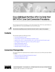
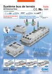
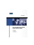
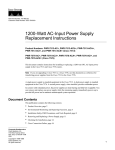
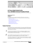
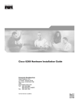
1
Octal-Port DMT ATU-C Line Card FRU Installation
and Replacement Notes
Commercial Environment Product Number: ATUC-8-DMT-1=
Outside-Plant Environment Product Number: ATUC-8-DMT-1-H=
This document provides an overview of and installation and replacement procedures for the octal-port
Discrete Multitone (DMT) asymmetric digital subscriber line (ADSL) Transmission Unit—central office
(ATU-C) line card (8xDMT). The 8xDMT is a field-replaceable unit (FRU) for the following chassis:
Warning
•
Cisco 6015—Use the 8xDMT version that is appropriate for the installation environment
(commercial or outside plant).
•
Cisco 6160—Use only the commercial version of the 8xDMT.
•
Cisco 6260—Use only the commercial version of the 8xDMT.
Only trained and qualified personnel should be allowed to install, replace, or service this equipment.
Contents
This document includes the following sections:
•
Introduction, page 2
•
Part and Tool Requirements, page 6
•
General Safety Precaution and Maintenance Guidelines
•
Removing and Installing the 8xDMT, page 12
•
Traffic Handling, page 14
•
Standards and Certifications, page 14
•
Related Documentation, page 15
•
Obtaining Documentation, page 15
•
Obtaining Technical Assistance, page 16
Corporate Headquarters:
Cisco Systems, Inc., 170 West Tasman Drive, San Jose, CA 95134-1706 USA
Copyright © 2002. Cisco Systems, Inc. All rights reserved.
Introduction
Introduction
The 8xDMT is designed for use in one of the following system configurations:
•
With a POTS splitter chassis—Provisions one modem directly and is physically connected to one
specific subscriber line through the POTS splitter chassis.
•
Without a POTS splitter chassis—Provisions one modem directly and is physically connected to one
specific subscriber line through the main distribution frame (MDF) connections.
The 8xDMT
•
Supports eight ADSL modem connections.
•
Converts ADSL modulation from the line into digital data streams to and from the NI-2 card.
•
Negotiates the line rate with the customer premises equipment (CPE) when it trains and bases the
rate on line quality and distance.
If provisioned, the 8xDMT rate adapts to the maximum bit rate negotiable on the line. The maximum bit
rate settings are provisioned in the management software.
Table 1 details the total available ADSL modem connections for each chassis.
Table 1
Note
Number of Available Modem Connections for Each Chassis
Chassis
Number of Available
8xDMT Slots
Chassis Slot Numbers for 8xDMTs
Total ADSL Modem
Connections
Cisco 6015
6
1 through 6
48
Cisco 6160
32
1 through 9 and 12 through 34
256
Cisco 6260
30
1 through 9 and 12 through 32
240
For line card intermixing information, refer to the appropriate hardware installation guide for
your chassis.
Introduction
2
OL-2189-01
Introduction
Faceplate Features
Figure 1 shows a close-up of the 8xDMT faceplate.
Note
The only cosmetic difference between the commercial version 8xDMT and outside-plant version of the
8xDMT is the part number silkscreened at the bottom of the card faceplate.
Figure 1
8xDMT Faceplate
1
2
3
STATUS
4
ACTIVE
ATU-C1
ATU-C2
ATU-C3
5
ATU-C4
ATU-C5
ATU-C6
ATU-C7
ATU-C8
45678
8X DMT8 GSI
6
1
Ejector lever
4
ACTIVE LED
2
Locking tab
5
Modem port status LEDs
3
STATUS LED
6
Extraction tab
Table 2 describes LEDs on the 8xDMT.
Table 2
8xDMT LEDs
LED
State
Function
STATUS
Green slow blinking
No errors, but no connection established.
Green fast blinking
The image download is in progress.
Green solid
NI-2 communication established.
Red
The self-test or line card has failed.
Off
The ATU-C line card has a power failure.
Faceplate Features
OL-2189-01
3
Introduction
Table 2
8xDMT LEDs (continued)
LED
State
Function
ACTIVE
Green solid
The line card is activated.
Off
The line card is not in service.
Green solid
Modem 1 is trained.
Green blinking
Training is in progress for modem 1.
Off
Modem 1 is idle.
Green solid
Modem 2 is trained.
Green blinking
Training is in progress for modem 2.
Off
Modem 2 is idle.
Green solid
Modem 3 is trained.
Green blinking
Training is in progress for modem 3.
Off
Modem 3 is idle.
Green solid
Modem 4 is trained.
Green blinking
Training is in progress for modem 4.
Off
Modem 4 is idle.
Green solid
Modem 5 is trained.
Green blinking
Training is in progress for modem 5.
Off
Modem 5 is idle.
Green solid
Modem 6 is trained.
Green blinking
Training is in progress for modem 6.
Off
Modem 6 is idle.
Green solid
Modem 7 is trained.
Green blinking
Training is in progress for modem 7.
Off
Modem 7 is idle.
Green solid
Modem 8 is trained.
Green blinking
Training is in progress for modem 8.
Off
Modem 8 is idle.
ATU-C 1
ATU-C 2
ATU-C 3
ATU-C 4
ATU-C 5
ATU-C 6
ATU-C 7
ATU-C 8
Faceplate Features
4
OL-2189-01
Introduction
Specifications
Table 3 lists the specifications for the commercial and the outside-plant versions of the 8xDMT.
Table 3
8xDMT Specifications
Specification
Standards supported
Description
•
ANSI T1.413, Category 1 only
•
ANSI T1.413, Annex F (Reduced NEXT)\
•
Universal Test & Operations PHY for ATM, Level 2; A
standard for transport of ATM cells over a 16-bit
parallel data bus. Refer to the ATM Forum document
af-phy-0039.000.
•
ITU G.992.1, Annex A (G.dmt)
•
ITU G.992.2. (G.lite)
•
ITU G.994.1. (G.hs)
External interfaces
8 (no connectors on card)
Data rates (per port)
Upstream: Up to 1024 kbps
Downstream: Up to 8.064 Mbps
Internal hardware
Dimensions
•
40 MHz Motorola MPC850 microprocessor
•
8MB SDRAM
•
1 Mb boot flash
•
1 kb serial EEPROM
Height: 6.07 in. (15.42 cm)
Depth: 8.50 in. (21.59 cm)
Width: 0.88 in. (2.24 cm)
Weight
0.875 lb (0.4 kg)
Power consumption
24W
Minimum software and
network management
requirement
Commercial version:
•
Cisco IOS—Release 12.1(6)DA
•
CDM1—Release 3.3(2) (optional)
Outside-plant version:
•
Cisco IOS—Release 12.2(5)DA
•
CDM—Release 3.4 (optional)
1. CDM = Cisco DSL Manager
Specifications
OL-2189-01
5
Part and Tool Requirements
Part and Tool Requirements
Table 4 lists the tools and equipment that you need to install and remove a 8xDMT.
Table 4
Check
Tool and Equipment Requirements Checklist
Tools and Equipment
8xDMT—Commercial or outside-plant version.
Equipment necessary for ESD protection—You need this equipment whenever you handle
Cisco chassis, modules, and cards.
Flat-head screwdriver.
Note
The system has no internal user-serviceable parts. However, you can add or remove an 8xDMT without
removing power from the system (hot swapping). See the “Hot Swapping Line Cards” section on page 11
for more information.
General Safety Precaution and Maintenance Guidelines
This section describes the following concepts:
•
General Safety Precautions, page 6
•
General Maintenance Guidelines, page 10
•
Preventing Electrostatic Discharge Damage, page 11
General Safety Precautions
Before working on the equipment, be aware of standard safety practices and the hazards involved in
working with electrical circuitry to prevent accidents. Adhere to the following cautions and warnings for
safe and hazard-free installation.
Note
To see translations of the warnings that appear in this publication, refer to the appropriate Regulatory
Compliance and Safety Information document for your system.
Caution
Before you start the installation procedures, read the entire document for important information and
safety warnings.
Caution
Proper ESD protection is required whenever you handle Cisco equipment. Installation and
maintenance personnel should be properly grounded by means of grounding straps to eliminate the
risk of ESD damage to the equipment. Equipment is subject to ESD damage whenever it is removed
from the chassis.
Part and Tool Requirements
6
OL-2189-01
General Safety Precaution and Maintenance Guidelines
Caution
If the power connections are improperly connected and power is applied while the cards are installed,
the cards and chassis could be damaged.
Caution
Service is interrupted only for the subscribers assigned to the line card that is being removed.
Caution
It is important that the chassis cooling fans run continuously while the system is powered.
Caution
Any card that is only partially connected to the backplane can disrupt system operation.
Caution
Installing the line cards in the chassis with the power leads reversed can damage the line cards.
Warning
This warning symbol means danger. You are in a situation that could cause bodily injury. Before you
work on any equipment, be aware of the hazards involved with electrical circuitry and be familiar
with standard practices for preventing accidents. To see translations of the warnings that appear
in this publication, refer to the Regulatory Compliance and Safety Information document that
accompanied this device.
Waarschuwing
Dit waarschuwingssymbool betekent gevaar. U verkeert in een situatie die lichamelijk letsel
kan veroorzaken. Voordat u aan enige apparatuur gaat werken, dient u zich bewust te zijn van
de bij elektrische schakelingen betrokken risico's en dient u op de hoogte te zijn van standaard
maatregelen om ongelukken te voorkomen. Voor vertalingen van de waarschuwingen die in
deze publicatie verschijnen, kunt u het document Regulatory Compliance and Safety Information
(Informatie over naleving van veiligheids- en andere voorschriften) raadplegen dat bij dit
toestel is ingesloten.
Varoitus
Tämä varoitusmerkki merkitsee vaaraa. Olet tilanteessa, joka voi johtaa ruumiinvammaan.
Ennen kuin työskentelet minkään laitteiston parissa, ota selvää sähkökytkentöihin liittyvistä
vaaroista ja tavanomaisista onnettomuuksien ehkäisykeinoista. Tässä julkaisussa esiintyvien
varoitusten käännökset löydät laitteen mukana olevasta Regulatory Compliance and Safety
Information -kirjasesta (määräysten noudattaminen ja tietoa turvallisuudesta).
Attention
Ce symbole d'avertissement indique un danger. Vous vous trouvez dans une situation pouvant
causer des blessures ou des dommages corporels. Avant de travailler sur un équipement, soyez
conscient des dangers posés par les circuits électriques et familiarisez-vous avec les
procédures couramment utilisées pour éviter les accidents. Pour prendre connaissance des
traductions d’avertissements figurant dans cette publication, consultez le document Regulatory
Compliance and Safety Information (Conformité aux règlements et consignes de sécurité) qui
accompagne cet appareil.
General Safety Precautions
OL-2189-01
7
General Safety Precaution and Maintenance Guidelines
Warnung
Dieses Warnsymbol bedeutet Gefahr. Sie befinden sich in einer Situation, die zu einer
Körperverletzung führen könnte. Bevor Sie mit der Arbeit an irgendeinem Gerät beginnen, seien
Sie sich der mit elektrischen Stromkreisen verbundenen Gefahren und der Standardpraktiken
zur Vermeidung von Unfällen bewußt. Übersetzungen der in dieser Veröffentlichung enthaltenen
Warnhinweise finden Sie im Dokument Regulatory Compliance and Safety Information
(Informationen zu behördlichen Vorschriften und Sicherheit), das zusammen mit diesem Gerät
geliefert wurde.
Avvertenza
Questo simbolo di avvertenza indica un pericolo. La situazione potrebbe causare infortuni alle
persone. Prima di lavorare su qualsiasi apparecchiatura, occorre conoscere i pericoli relativi
ai circuiti elettrici ed essere al corrente delle pratiche standard per la prevenzione di incidenti.
La traduzione delle avvertenze riportate in questa pubblicazione si trova nel documento
Regulatory Compliance and Safety Information (Conformità alle norme e informazioni sulla
sicurezza) che accompagna questo dispositivo.
Advarsel
Dette varselsymbolet betyr fare. Du befinner deg i en situasjon som kan føre til personskade. Før
du utfører arbeid på utstyr, må du vare oppmerksom på de faremomentene som elektriske kretser
innebærer, samt gjøre deg kjent med vanlig praksis når det gjelder å unngå ulykker. Hvis du vil
se oversettelser av de advarslene som finnes i denne publikasjonen, kan du se i dokumentet
Regulatory Compliance and Safety Information (Overholdelse av forskrifter og
sikkerhetsinformasjon) som ble levert med denne enheten.
Aviso
Este símbolo de aviso indica perigo. Encontra-se numa situação que lhe poderá causar danos
físicos. Antes de começar a trabalhar com qualquer equipamento, familiarize-se com os perigos
relacionados com circuitos eléctricos, e com quaisquer práticas comuns que possam prevenir
possíveis acidentes. Para ver as traduções dos avisos que constam desta publicação, consulte
o documento Regulatory Compliance and Safety Information (Informação de Segurança e
Disposições Reguladoras) que acompanha este dispositivo.
¡Advertencia!
Este símbolo de aviso significa peligro. Existe riesgo para su integridad física. Antes de
manipular cualquier equipo, considerar los riesgos que entraña la corriente eléctrica y
familiarizarse con los procedimientos estándar de prevención de accidentes. Para ver una
traducción de las advertencias que aparecen en esta publicación, consultar el documento
titulado Regulatory Compliance and Safety Information (Información sobre seguridad y
conformidad con las disposiciones reglamentarias) que se acompaña con este dispositivo.
Varning!
Denna varningssymbol signalerar fara. Du befinner dig i en situation som kan leda till
personskada. Innan du utför arbete på någon utrustning måste du vara medveten om farorna med
elkretsar och känna till vanligt förfarande för att förebygga skador. Se förklaringar av de
varningar som förkommer i denna publikation i dokumentet Regulatory Compliance and Safety
Information (Efterrättelse av föreskrifter och säkerhetsinformation), vilket medföljer
denna anordning.
Warning
Read the installation instructions before you connect the system to its power source.
Warning
Use copper conductors only.
General Safety Precautions
8
OL-2189-01
General Safety Precaution and Maintenance Guidelines
Warning
Never install telephone wiring during an electrical storm.
Warning
Do not reach into a vacant slot or chassis while you install or remove a module or a fan. Exposed
circuitry could constitute an energy hazard.
Warning
Blank faceplates and cover panels serve three important functions: they prevent exposure to
hazardous voltages and currents inside the chassis; they contain electromagnetic interference (EMI)
that might disrupt other equipment; and they direct the flow of cooling air through the chassis. Do not
operate the system unless all cards, faceplates, front covers, and rear covers are in place.
Warning
Do not work on the system or connect or disconnect cables during periods of lightning activity.
Warning
Use caution when installing or modifying telephone lines.
Warning
Ultimate disposal of this product should be handled according to all national laws and regulations.
Warning
This unit is intended for installation in restricted access areas. A restricted access area is where
access can only be gained by service personnel through the use of a special tool, lock and key, or
other means of security, and is controlled by the authority responsible for the location.
Warning
Connect the unit only to DC power source that complies with the Safety Extra-Low Voltage (SELV)
requirements in IEC 60950 based safety standards.
Warning
This product requires short-circuit (overcurrent) protection, to be provided as part of the building
installation. Install only in accordance with national and local wiring regulations.
Warning
Never install telephone jacks in wet locations unless the jack is specifically designed for
wet locations.
Warning
Avoid using a telephone (other than a cordless type) during an electrical storm. There may be a remote
risk of electric shock from lightning.
Warning
Do not use a telephone to report a gas leak in the vicinity of the leak.
General Safety Precautions
OL-2189-01
9
General Safety Precaution and Maintenance Guidelines
Warning
Never touch uninsulated telephone wires or terminals unless the telephone line has been
disconnected at the network interface.
Warning
Do not use this product near water; for example, near a bathtub, washbowl, kitchen sink or laundry
tub, in a wet basement, or near a swimming pool.
Warning
During this procedure, wear grounding wrist straps to avoid ESD damage to the card. Do not directly
touch the backplane with your hand or any metal tool, or you could shock yourself.
Warning
Before opening the chassis, disconnect the telephone-network cables to avoid contact with
telephone-network voltages
Warning
This equipment is to be installed and maintained by service personnel only as defined by AS/NZS 3260
Clause 1.2.14.3 Service Personnel.
Warning
To reduce the risk of fire, use only No. 26 AWG or larger telecommunication line cord.
General Maintenance Guidelines
This section covers the following topics:
•
Installation and Replacement Suggestions, page 10
•
Hot Swapping Line Cards, page 11
Installation and Replacement Suggestions
The following examples list recommended installation and replacement practices for the 8xDMTs.
Caution
Any line card that is only partially connected to the backplane can disrupt system operation.
•
Do not force the line card into its slot. This action can damage the pins on the backplane if they are
not aligned properly with the line card.
•
Ensure that the line card is straight and not at an angle when you install the line card in the slot.
Installing the line card at an angle can damage the card. Use the guide rails to install the line
card correctly.
•
Fully depress the ejector levers to ensure that the card connector mates with the backplane correctly.
Firmly seat the line card in the slot.
General Maintenance Guidelines
10
OL-2189-01
General Safety Precaution and Maintenance Guidelines
Hot Swapping Line Cards
The 8xDMT can be hot swapped. Hot swapping allows you to remove, replace, and rearrange the line
cards without disconnecting the system power. When the system detects that you have added or removed
an 8xDMT, it automatically runs diagnostic and discovery routines and acknowledges the presence or
absence of the line card.
If you remove and replace an 8xDMT with another 8xDMT, the newly installed line card receives
the same provisioning as the original line card. The system resumes operation without any
operator intervention.
If an unprovisioned line card is installed for the first time, the system identifies it as present but
unprovisioned. Instructions for provisioning the line card are found in the appropriate software guide for
your chassis.
Preventing Electrostatic Discharge Damage
Proper ESD protection is required whenever you handle Cisco equipment. ESD damage, which can occur
when electronic cards or components are improperly handled, results in complete or intermittent
failures. Use an antistatic strap when you handle any card or component.
Follow these guidelines to prevent ESD damage:
Caution
•
Always use an ESD ankle or wrist strap and ensure that the wrist strap makes good skin contact.
•
Connect the equipment end of the strap to the ESD jack on the front of the chassis.
•
When you install a component, use available ejector levers or captive installation screws to properly
seat the bus connectors in the backplane or midplane. These devices prevent accidental removal,
provide proper grounding for the system, and help ensure that bus connectors are properly seated.
•
When you remove a component, use available ejector levers or captive installation screws to release
the bus connectors from the backplane or midplane.
•
Avoid touching the printed circuit boards or connectors on the NI-2 cards or line cards.
•
Place a removed component board-side-up on an antistatic surface or in a static-shielding
container. If you plan to return the component to the factory, immediately place it in a
static-shielding container.
•
Avoid contact between the printed circuit boards and clothing. The wrist strap protects components
from ESD voltages on the body only; ESD voltages on clothing can still cause damage.
Periodically check the resistance value of the antistatic strap. Ensure that the measurement is between 1
and 10 megohms.
Preventing Electrostatic Discharge Damage
OL-2189-01
11
Removing and Installing the 8xDMT
Removing and Installing the 8xDMT
The following sections describe how to remove or install an 8xDMT.
Caution
Note
Proper ESD protection is required whenever you handle Cisco equipment. Installation and
maintenance personnel should be properly grounded by means of grounding straps to eliminate the
risk of ESD damage to the equipment. Equipment is subject to ESD damage whenever it is removed
from the chassis.
All cards must be fully seated in the chassis. Push on the faceplate of each card to be sure that the card
is fully seated.
Removing an 8xDMT
Complete the following steps to remove an 8xDMT from the chassis:
Step 1
Connect a grounding strap to the ESD grounding jack on the chassis.
Step 2
Use a flat-head screwdriver to move the locking tab from the locked to the unlocked position. Be sure to
turn the locking tab so that it does not overlap the line card ejector lever as shown in Figure 2.
Positioning the Locking Tab for the 8xDMT
Locked
position
Unlocked
position
27035
Figure 2
Step 3
Lift the ejector lever to disconnect the line card from the backplane.
Step 4
Carefully slide the line card out of the slot.
Either replace the line card that you remove, or insert a blank faceplate in the empty slot. See the
“Installing an 8xDMT” section on page 13 for 8xDMT installation instructions. See the “Installing a
Blank Faceplate” section on page 14 for blank faceplate installation instructions.
Warning
Blank faceplates and cover panels serve three important functions: they prevent exposure to
hazardous voltages and currents inside the chassis; they contain electromagnetic interference (EMI)
that might disrupt other equipment; and they direct the flow of cooling air through the chassis. Do not
operate the system unless all cards, faceplates, front covers, and rear covers are in place.
Removing and Installing the 8xDMT
12
OL-2189-01
Removing and Installing the 8xDMT
Installing an 8xDMT
Complete the following steps to install an 8xDMT in the chassis:
Step 1
Connect a grounding strap to the ESD grounding jack on the chassis.
Step 2
Hold the line card horizontally (Cisco 6015) or vertically (Cisco 6160 or Cisco 6260), with the faceplate
toward you and the connectors facing the chassis slot.
Step 3
Align the line card edges with the guides at the left and right (Cisco 6015) or top and bottom (Cisco 6160
or Cisco 6260) of the slot in the chassis.
Step 4
Lift the ejector lever and gently apply pressure to the faceplate while pushing the line card into the slot.
Figure 3 shows an example of the 8xDMT installation. The installation procedures will be similar for
the other chassis.
Figure 3
Installation of the 8xDMT
NI-2
-155SM
-155SM
ACO
RESET
TRNK
1
TR T
R
EX X
C
S
S
TT SL
TK
A A
T T
T
X
ALARMS
R
X
CRITIC
AL
MAJOR
MINOR
POWE
R
STATU
S
ACTIV
E
T
X
2
C
N
S
L
TR T
R
X XC
A
U
X
SBTD
50952
FAN 1
FAN 2
R
X
Step 5
Push on the faceplate of the line card to fully seat the card.
Step 6
Press down on the ejector lever to secure the line card and connect it to the backplane.
Step 7
Use a flat-head screwdriver to turn the locking tab so that it overlaps the line card ejector lever to
prevent inadvertent dislodging. Figure 2 shows how to position the locking tabs.
Step 8
Verify that the STATUS LED is solid green after the brief self-test. If the STATUS LED is not green
after the self-test, see the appropriate hardware guide for your chassis for troubleshooting procedures.
Note
If you are installing the line card for the first time, refer to the provisioning procedures in the appropriate
software guide for your chassis.
Installing an 8xDMT
OL-2189-01
13
Traffic Handling
Installing a Blank Faceplate
Complete the following steps to install a blank faceplate in the chassis:
Note
Blank faceplates should occupy any empty line card slots in the chassis. The blank faceplate installation
is similar to the line card installation.
Step 1
Connect a grounding strap to the ESD grounding jack.
Step 2
Align the blank faceplate edges with the slot guides in the chassis.
Step 3
Lift the ejector lever and gently apply pressure to the faceplate while pushing the blank faceplate into
the slot.
Step 4
Push on the faceplate to fully seat the blank faceplate.
Step 5
Press down on the ejector lever to secure the faceplate.
Traffic Handling
The maximum downstream rate per port for the 8xDMT is 8.064 Mbps. The maximum upstream rate per
port is 1024 kbps.
Downstream refers to data that is coming from the NI-2 card to the subscriber lines. Upstream refers to
data that is coming from the subscriber lines to the NI-2 card.
Standards and Certifications
Table 5 lists 8xDMT standards and certifications.
Table 5
Standards and Certifications
Category
Description
Product safety
UL 1950, 3rd Edition
EN 60950 2nd Edition, Amendments 1, 2, 3, 4, and 11
IEC 60950 2nd Edition, Amendments 1, 2, 3, and 4
AS/NZS 3260
EMI
EN55022/CISPR22
FCC Part 15, Class B
AS/ANS 3548
ICES-003
VCCI
BSMI (CNS 13438)
Installing a Blank Faceplate
14
OL-2189-01
Related Documentation
Table 5
Standards and Certifications (continued)
Category
Description
Immunity
EN/IEC 61000-4-2
EN/IEC 61000-4-3
EN/IEC 61000-4-4
EN/IEC 61000-4-5
EN/IEC 61000-4-6
NEBS
Telcordia GR-63-CORE
Telcordia GR-1089-CORE
SR-3580 Level 3
Telecom
IC-CS03
ETSI
EN/ETSI 300-386.1
EN/ETSI 300-386.2
Related Documentation
A complete list of all DSL product related documentation is available on the World Wide Web at
http://www.cisco.com/univercd/cc/td/doc/product/dsl_prod/index.htm
Obtaining Documentation
The following sections explain how to obtain documentation from Cisco Systems.
World Wide Web
You can access the most current Cisco documentation on the World Wide Web at the following URL:
http://www.cisco.com
Translated documentation is available at the following URL:
http://www.cisco.com/public/countries_languages.shtml
Documentation CD-ROM
Cisco documentation and additional literature are available in a Cisco Documentation CD-ROM
package, which is shipped with your product. The Documentation CD-ROM is updated monthly and may
be more current than printed documentation. The CD-ROM package is available as a single unit or
through an annual subscription. Registered Cisco.com users can order the Documentation CD-ROM
through the online Subscription Store:
http://www.cisco.com/go/subscription
Related Documentation
OL-2189-01
15
Obtaining Technical Assistance
Documentation Feedback
If you are reading Cisco product documentation on Cisco.com, you can submit technical comments
electronically. Click Leave Feedback at the bottom of the Cisco Documentation home page. After you
complete the form, print it out and fax it to Cisco at 408 527-0730.
You can e-mail your comments to [email protected].
To submit your comments by mail, use the response card behind the front cover of your document, or
write to the following address:
Cisco Systems
Attn: Document Resource Connection
170 West Tasman Drive
San Jose, CA 95134-9883
We appreciate your comments.
Obtaining Technical Assistance
Cisco provides Cisco.com as a starting point for all technical assistance. Customers and partners can
obtain documentation, troubleshooting tips, and sample configurations from online tools by using the
Cisco Technical Assistance Center (TAC) Web Site. Cisco.com registered users have complete access to
the technical support resources on the Cisco TAC Web Site.
Cisco.com
Cisco.com is the foundation of a suite of interactive, networked services that provides immediate, open
access to Cisco information, networking solutions, services, programs, and resources at any time, from
anywhere in the world.
Cisco.com is a highly integrated Internet application and a powerful, easy-to-use tool that provides a
broad range of features and services to help you to
•
Streamline business processes and improve productivity
•
Resolve technical issues with online support
•
Download and test software packages
•
Order Cisco learning materials and merchandise
•
Register for online skill assessment, training, and certification programs
You can self-register on Cisco.com to obtain customized information and service. To access Cisco.com,
go to the following URL:
http://www.cisco.com
Documentation Feedback
16
OL-2189-01
Obtaining Technical Assistance
Technical Assistance Center
The Cisco TAC is available to all customers who need technical assistance with a Cisco product,
technology, or solution. Two types of support are available through the Cisco TAC: the Cisco TAC
Web Site and the Cisco TAC Escalation Center.
Inquiries to Cisco TAC are categorized according to the urgency of the issue:
•
Priority level 4 (P4)—You need information or assistance concerning Cisco product capabilities,
product installation, or basic product configuration.
•
Priority level 3 (P3)—Your network performance is degraded. Network functionality is noticeably
impaired, but most business operations continue.
•
Priority level 2 (P2)—Your production network is severely degraded, affecting significant aspects
of business operations. No workaround is available.
•
Priority level 1 (P1)—Your production network is down, and a critical impact to business operations
will occur if service is not restored quickly. No workaround is available.
Which Cisco TAC resource you choose is based on the priority of the problem and the conditions of
service contracts, when applicable.
Cisco TAC Web Site
The Cisco TAC Web Site allows you to resolve P3 and P4 issues yourself, saving both cost and time. The
site provides around-the-clock access to online tools, knowledge bases, and software. To access the
Cisco TAC Web Site, go to the following URL:
http://www.cisco.com/tac
All customers, partners, and resellers who have a valid Cisco services contract have complete access to
the technical support resources on the Cisco TAC Web Site. The Cisco TAC Web Site requires a
Cisco.com login ID and password. If you have a valid service contract but do not have a login ID or
password, go to the following URL to register:
http://www.cisco.com/register/
If you cannot resolve your technical issues by using the Cisco TAC Web Site, and you are a Cisco.com
registered user, you can open a case online by using the TAC Case Open tool at the following URL:
http://www.cisco.com/tac/caseopen
If you have Internet access, it is recommended that you open P3 and P4 cases through the Cisco TAC
Web Site.
Cisco TAC Escalation Center
The Cisco TAC Escalation Center addresses issues that are classified as priority level 1 or priority
level 2; these classifications are assigned when severe network degradation significantly impacts
business operations. When you contact the TAC Escalation Center with a P1 or P2 problem, a Cisco TAC
engineer will automatically open a case.
To obtain a directory of toll-free Cisco TAC telephone numbers for your country, go to the following
URL:
http://www.cisco.com/warp/public/687/Directory/DirTAC.shtml
Technical Assistance Center
OL-2189-01
17
Obtaining Technical Assistance
Before calling, please check with your network operations center to determine the level of Cisco support
services to which your company is entitled; for example, SMARTnet, SMARTnet Onsite, or Network
Supported Accounts (NSA). In addition, please have available your service agreement number and your
product serial number.
This document is to be used in conjunction with the documents listed in the “Related Documentation” section.
CCIP, the Cisco Arrow logo, the Cisco Powered Network mark, the Cisco Systems Verified logo, Cisco Unity, Follow Me Browsing, FormShare, Internet
Quotient, iQ Breakthrough, iQ Expertise, iQ FastTrack, the iQ Logo, iQ Net Readiness Scorecard, Networking Academy, ScriptShare, SMARTnet,
TransPath, and Voice LAN are trademarks of Cisco Systems, Inc.; Changing the Way We Work, Live, Play, and Learn, Discover All That’s Possible, The
Fastest Way to Increase Your Internet Quotient, and iQuick Study are service marks of Cisco Systems, Inc.; and Aironet, ASIST, BPX, Catalyst, CCDA,
CCDP, CCIE, CCNA, CCNP, Cisco, the Cisco Certified Internetwork Expert logo, Cisco IOS, the Cisco IOS logo, Cisco Press, Cisco Systems, Cisco
Systems Capital, the Cisco Systems logo, Empowering the Internet Generation, Enterprise/Solver, EtherChannel, EtherSwitch, Fast Step, GigaStack,
IOS, IP/TV, LightStream, MGX, MICA, the Networkers logo, Network Registrar, Packet, PIX, Post-Routing, Pre-Routing, RateMUX, Registrar,
SlideCast, StrataView Plus, Stratm, SwitchProbe, TeleRouter, and VCO are registered trademarks of Cisco Systems, Inc. and/or its affiliates in the U.S.
and certain other countries.
All other trademarks mentioned in this document or Web site are the property of their respective owners. The use of the word partner does not imply a
partnership relationship between Cisco and any other company. (0206R)
Copyright © 2002, Cisco Systems, Inc.
All rights reserved.
Technical Assistance Center
18
OL-2189-01