1
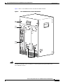
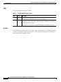
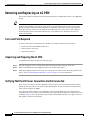
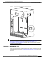
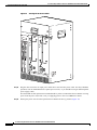
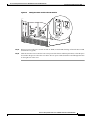
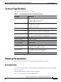
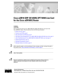
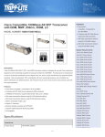
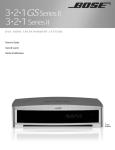
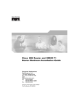
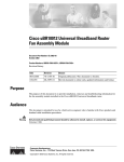
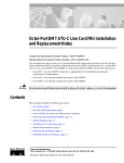
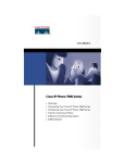
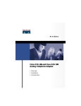
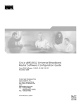
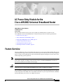
AC Power Entry Module for the
Cisco uBR10012 Universal Broadband Router
UBR10-PWR-AC, UBR10-PWR-AC=,
78-13996-01 Rev. B0
June 10, 2002
This document describes the AC power entry module (AC PEM) and how to install it in the
Cisco uBR10012 universal broadband router. This document provides the following information:
•
Feature Overview, page 1
•
Safety Information and Warnings, page 6
•
Removing and Replacing an AC PEM, page 10
•
Technical Specifications, page 23
•
Obtaining Documentation, page 23
•
Obtaining Technical Assistance, page 24
Feature Overview
The Cisco uBR10012 router can optionally ship with two AC power entry modules (PEMs) that provide
a redundant power supply to the system. One AC PEM can provide sufficient power for a fully configured
chassis, so that if one AC PEM fails, the other automatically begins providing power for the entire router,
without impacting system operations.
Note
Caution
You should be using Cisco IOS Release 12.2(4)XF1, Cisco IOS Release 12.2(4)BC1a, or a later
release when using the AC PEM. If using an earlier release, the show environment command will
not correctly identify the AC PEM’s error messages.
The Cisco uBR10012 router supports using either the AC PEM or the DC PEM, but it does not
support mixing AC and DC PEMs. Both PEMs must be either AC PEMs or DC PEMs.
The AC PEMs use standard 200–240 VAC (50/60 Hz) input power obtained through power receptacles
on the front panel of each PEM. The two AC PEMs convert the AC power to provide filtered, redundant,
and load shared DC power to the Cisco uBR10012 chassis.
AC Power Entry Module for the Cisco uBR10012 Universal Broadband Router
78-13996-01 Rev. B0
1
AC Power Entry Module for the Cisco uBR10012 Universal Broadband Router
Feature Overview
Caution
Tips
The AC PEMs cannot be used with a 100–120 VAC input power source.
For fully redundant power protection, use either an uninterruptible power supply (UPS) or a separate
AC-input power source for each AC PEM.
This document contains the procedures to replace an existing second (redundant) AC PEM and to replace
both AC PEMs.
Note
You do not need to shut down the Cisco uBR10012 router to replace a redundant AC PEM. If you are
replacing both AC PEMs, you can replace one, bring it online, and then replace the other one to avoid
shutting down the system.
Caution
Although one AC PEM can provide sufficient power for a fully configured Cisco uBR10012 chassis,
the system should not be run for an extended period of time with only one AC PEM. If an AC PEM
fails, order and install a replacement AC PEM as soon as possible. The product order number for a
replacement AC PEM is UBR10-PWR-AC=. For proper airflow, cooling, and safety, do not remove
the failed unit until the replacement unit is available for installation.
Physical Description
Figure 1 shows the front panel of the AC PEM for the Cisco uBR10012 router.
Figure 1
AC PEM Front Panel
POWER
AC power
cord clips
FAULT
AC power plug
62520
AC power switch
AC Power Entry Module for the Cisco uBR10012 Universal Broadband Router
2
78-13996-01 Rev. B0
AC Power Entry Module for the Cisco uBR10012 Universal Broadband Router
Feature Overview
Figure 2 shows a Cisco uBR10012 router with dual AC PEMs installed.
Figure 2
Cisco uBR10012 Router with AC PEM Modules
Fan
assembly
LCD
panel
POWER
CISCO
10000
CISCO
10000
FAULT
POWER
C
O
N
S
O
C
LE
O
N
S
O
LE
AU
X
FAULT
AU
X
A
C
A
C
TIV
IT
Y
1
OT
0
OT
E
TH
E
LIN RN
K ET
SL
SL
1
OT
0
OT
SL
SL
PRE
module
TIV
IT
E
TH Y
E
LIN RN
E
T
K
ALARMS
ALARMS
A
C
O
A
C
O
C
R
IT
IC
C
A
M
R
L
A
IT
IC
JO
R
IN
O
R
TA
TU
S
FA
IL
L
A
JO
R
M
IN
O
R
S
TA
TU
S
FA
62521
IL
PERFORMANCE ROUTING ENGINE
S
A
M
PERFORMANCE ROUTING ENGINE
M
PEM
Caution
Do not attempt to lift the Cisco uBR10012 chassis by using the two handles on the front of the
AC PEM. The handles on the AC PEM are for removing and inserting the PEM into the
Cisco uBR10012 chassis.
AC Power Entry Module for the Cisco uBR10012 Universal Broadband Router
78-13996-01 Rev. B0
3
AC Power Entry Module for the Cisco uBR10012 Universal Broadband Router
Feature Overview
LEDs
Table 1 describes the LEDs on the AC PEM.
Table 1
AC PEM LEDs and Their Function
LED
Color
Description
Power
Green
The PEM is on, is receiving power from the AC power source, and is providing
power to the Cisco uBR10012 chassis (normal operations).
Fault
Yellow
Indicates that AC-input power is being received by the PEM, but that the PEM is
not supplying power to the chassis, typically because the PEM’s power switch is
turned to the standby position.
If the power switch is in the ON position, the PEM is not operating correctly.
Air Flow
The AC PEM works together with the fan assembly module to ensure that the Cisco uBR10012 chassis
is properly cooled during normal operation. Figure 3 shows the airflow through the Cisco uBR10012
chassis when dual AC PEMs are installed.
AC Power Entry Module for the Cisco uBR10012 Universal Broadband Router
4
78-13996-01 Rev. B0
AC Power Entry Module for the Cisco uBR10012 Universal Broadband Router
Feature Overview
Figure 3
Airflow Through the Cisco uBR10012 Chassis with Dual AC PEMs
CISCO
10000
POWER
CISCO
10000
FAULT
C
O
N
S
O
POWER
C
LE
O
N
S
O
LE
AU
X
AU
X
FAULT
A
C
TIV
IT
TH Y
E
LIN RN
E
T
K
A
C
E
1
OT
0
OT
SL
SL
1
OT
0
OT
SL
SL
TIV
IT
Y
E
TH
E
LIN RN
K ET
ALARMS
ALARMS
A
C
O
A
C
O
C
R
IT
IC
C
A
M
R
L
A
IT
IC
JO
R
IN
O
R
TA
TU
S
FA
IL
L
A
JO
R
M
IN
O
R
S
TA
TU
S
FA
62522
IL
PERFORMANCE ROUTING ENGINE
S
A
M
PERFORMANCE ROUTING ENGINE
M
Note
Figure 3 shows the Cisco uBR10012 chassis without the front bezel installed, but the front bezel
should be installed during normal operation so that the air filter in the bezel can filter the incoming
air before it enters the chassis.
AC Power Entry Module for the Cisco uBR10012 Universal Broadband Router
78-13996-01 Rev. B0
5
AC Power Entry Module for the Cisco uBR10012 Universal Broadband Router
Safety Information and Warnings
Power Supply Cables
The AC PEM requires different power supply cables, depending on the country of operation. Table 2 lists
the product order numbers for the power supply cables that are available for the AC PEM for the
Cisco uBR10012 universal broadband router.
Table 2
Power Cables for the AC Power Entry Module for the Cisco uBR10012 Router
Product Order Number
Description
CAB-UBR10-AC-US
North America—Uses a locking NEMA L6-20 connector at
the end that plugs into the AC power source.
CAB-UBR10-AC-AR
Argentina
CAB-UBR10-AC-AU
Australia/New Zealand
CAB-UBR10-AC-CH
China
CAB-UBR10-AC-EU
Europe
CAB-UBR10-AC-IT
Italy
CAB-UBR10-AC-JP
Japan
CAB-UBR10-AC-UK
United Kingdom
Safety Information and Warnings
Following are safety guidelines that you should follow when working with any equipment that connects
to electrical power.
Warning
Only trained and qualified personnel should be allowed to install, replace, or service this
equipment. (To see translations of the warnings that appear in this publication, refer to the
appendix “Translated Safety Warnings” in the installation guide that accompanied this device.)
Safety Warnings
Warning
This warning symbol means danger. You are in a situation that could cause bodily injury. Before
you work on any equipment, be aware of the hazards involved with electrical circuitry and be
familiar with standard practices for preventing accidents. (To see translations of the warnings
that appear in this publication, refer to the appendix “Translated Safety Warnings” in the
installation guide that accompanied this device.)
Waarschuwing
Dit waarschuwingssymbool betekent gevaar. U verkeert in een situatie die lichamelijk letsel
kan veroorzaken. Voordat u aan enige apparatuur gaat werken, dient u zich bewust te zijn van
de bij elektrische schakelingen betrokken risico’s en dient u op de hoogte te zijn van standaard
maatregelen om ongelukken te voorkomen. (Voor vertalingen van de waarschuwingen die in
deze publicatie verschijnen, kunt u het aanhangsel “Translated Safety Warnings” (Vertalingen
van veiligheidsvoorschriften) in de installatiegids die bij dit toestel is ingesloten, raadplegen.
AC Power Entry Module for the Cisco uBR10012 Universal Broadband Router
6
78-13996-01 Rev. B0
AC Power Entry Module for the Cisco uBR10012 Universal Broadband Router
Safety Information and Warnings
Varoitus
Tämä varoitusmerkki merkitsee vaaraa. Olet tilanteessa, joka voi johtaa ruumiinvammaan.
Ennen kuin työskentelet minkään laitteiston parissa, ota selvää sähkökytkentöihin liittyvistä
vaaroista ja tavanomaisista onnettomuuksien ehkäisykeinoista. (Tässä julkaisussa esiintyvien
varoitusten käännökset löydät tämän laitteen mukana olevan asennusoppaan liitteestä
“Translated Safety Warnings” (käännetyt turvallisuutta koskevat varoitukset).)
Attention
Ce symbole d’avertissement indique un danger. Vous vous trouvez dans une situation pouvant
entraîner des blessures. Avant d’accéder à cet équipement, soyez conscient des dangers posés
par les circuits électriques et familiarisez-vous avec les procédures courantes de prévention
des accidents. Pour obtenir les traductions des mises en garde figurant dans cette publication,
veuillez consulter l’annexe intitulée « Translated Safety Warnings » (Traduction des avis de
sécurité) dans le guide d’installation qui accompagne cet appareil.
Warnung
Dieses Warnsymbol bedeutet Gefahr. Sie befinden sich in einer Situation, die zu einer
Körperverletzung führen könnte. Bevor Sie mit der Arbeit an irgendeinem Gerät beginnen, seien
Sie sich der mit elektrischen Stromkreisen verbundenen Gefahren und der Standardpraktiken
zur Vermeidung von Unfällen bewußt. (Übersetzungen der in dieser Veröffentlichung
enthaltenen Warnhinweise finden Sie im Anhang mit dem Titel “Translated Safety Warnings”
(Übersetzung der Warnhinweise) in der diesem Gerät beiliegenden Installationsanleitung.)
Avvertenza
Questo simbolo di avvertenza indica un pericolo. Si è in una situazione che può causare
infortuni. Prima di lavorare su qualsiasi apparecchiatura, occorre conoscere i pericoli relativi
ai circuiti elettrici ed essere al corrente delle pratiche standard per la prevenzione di incidenti.
La traduzione delle avvertenze riportate in questa pubblicazione si trova nell’appendice,
“Translated Safety Warnings” (Traduzione delle avvertenze di sicurezza), del manuale
d’installazione che accompagna questo dispositivo.
Advarsel
Dette varselsymbolet betyr fare. Du befinner deg i en situasjon som kan føre til personskade. Før
du utfører arbeid på utstyr, må du være oppmerksom på de faremomentene som elektriske
kretser innebærer, samt gjøre deg kjent med vanlig praksis når det gjelder å unngå ulykker.
(Hvis du vil se oversettelser av de advarslene som finnes i denne publikasjonen, kan du se i
vedlegget “Translated Safety Warnings” [Oversatte sikkerhetsadvarsler] i
installasjonsveiledningen som ble levert med denne enheten.)
Aviso
Este símbolo de aviso indica perigo. Encontra-se numa situação que lhe poderá causar danos
fisicos. Antes de começar a trabalhar com qualquer equipamento, familiarize-se com os perigos
relacionados com circuitos eléctricos, e com quaisquer práticas comuns que possam prevenir
possíveis acidentes. (Para ver as traduções dos avisos que constam desta publicação, consulte
o apêndice “Translated Safety Warnings” - “Traduções dos Avisos de Segurança”, no guia de
instalação que acompanha este dispositivo).
AC Power Entry Module for the Cisco uBR10012 Universal Broadband Router
78-13996-01 Rev. B0
7
AC Power Entry Module for the Cisco uBR10012 Universal Broadband Router
Safety Information and Warnings
¡Advertencia!
Este símbolo de aviso significa peligro. Existe riesgo para su integridad física. Antes de
manipular cualquier equipo, considerar los riesgos que entraña la corriente eléctrica y
familiarizarse con los procedimientos estándar de prevención de accidentes. (Para ver
traducciones de las advertencias que aparecen en esta publicación, consultar el apéndice
titulado “Translated Safety Warnings,” en la guía de instalación que se acompaña con este
dispositivo.)
Varning!
Denna varningssymbol signalerar fara. Du befinner dig i en situation som kan leda till
personskada. Innan du utför arbete på någon utrustning måste du vara medveten om farorna med
elkretsar och känna till vanligt förfarande för att förebygga skador. (Se förklaringar av de
varningar som förekommer i denna publikation i appendix “Translated Safety Warnings”
[Översatta säkerhetsvarningar] i den installationshandbok som medföljer denna anordning.)
Warning
Never defeat the ground conductor or operate the equipment in the absence of a suitably installed
ground conductor. Contact the appropriate electrical inspection authority or an electrician if you
are uncertain that suitable grounding is available. (To see translations of the warnings that appear
in this publication, refer to the appendix “Translated Safety Warnings” in the installation guide
that accompanied this device.)
Warning
Only trained and qualified personnel should be allowed to install, replace, or service this
equipment. (To see translations of the warnings that appear in this publication, refer to the
appendix “Translated Safety Warnings” in the installation guide that accompanied this device.)
Warning
This equipment must be installed and maintained by service personnel as defined by AS/NZS 3260.
Incorrectly connecting this equipment to a general purpose outlet could be hazardous. The
telecommunications lines must be disconnected 1) before unplugging the main power connector
and/or 2) while the housing is open. (To see translations of the warnings that appear in this
publication, refer to the appendix “Translated Safety Warnings” in the installation guide that
accompanied this device.)
Warning
Care must be given to connecting units to the supply circuit so that wiring is not overloaded. (To
see translations of the warnings that appear in this publication, refer to the appendix “Translated
Safety Warnings” in the installation guide that accompanied this device.)
AC Power Entry Module for the Cisco uBR10012 Universal Broadband Router
8
78-13996-01 Rev. B0
AC Power Entry Module for the Cisco uBR10012 Universal Broadband Router
Safety Information and Warnings
Electrical Equipment Guidelines
Follow these basic guidelines when working with any electrical equipment:
•
Before beginning any procedures requiring access to the chassis interior, locate the emergency
power-off switch for the room in which you are working.
•
Disconnect all power and external cables before moving a chassis.
•
Do not work alone when potentially hazardous conditions exist.
•
Never assume that power has been disconnected from a circuit; always check.
•
Do not perform any action that creates a potential hazard to people or makes the equipment unsafe.
•
Carefully examine your work area for possible hazards such as moist floors, ungrounded power
extension cables, and missing safety grounds.
Preventing Electrostatic Discharge Damage
Electrostatic discharge (ESD) damage, which occurs when electronic cards or components are
improperly handled, can result in complete or intermittent failures. The AC PEMs contain a printed
circuit card that is fixed in a metal carrier. Electromagnetic interference (EMI) shielding and connectors
are integral components of the carrier. Although the metal carrier helps to protect the cards from ESD,
use an antistatic strap each time you handle the modules.
Following are guidelines for preventing ESD damage:
Caution
•
Always use an ESD-preventive wrist or ankle strap and ensure that it makes good skin contact.
Before removing a card from the chassis, connect the equipment end of the strap to a bare metal,
unpainted surface on the chassis or rack-mount.
•
Handle components by the carrier edges only; avoid touching the card components or any connector
pins.
•
When removing a module, place it on an antistatic surface or in a static-shielding bag. If the module
will be returned to the factory, immediately place it in a static-shielding bag.
•
Avoid contact between the modules and clothing. The wrist strap protects the card from ESD
voltages on the body only; ESD voltages on clothing can still cause damage.
For safety, periodically check the resistance value of the antistatic strap. The measurement should be
between 1 and 10 megohms.
AC Power Entry Module for the Cisco uBR10012 Universal Broadband Router
78-13996-01 Rev. B0
9
AC Power Entry Module for the Cisco uBR10012 Universal Broadband Router
Removing and Replacing an AC PEM
Removing and Replacing an AC PEM
This section contains information on removing and replacing AC PEM modules in the Cisco uBR10012
chassis.
Tip
The AC PEM is operating correctly when its Power LED is on (green). When the Fault LED is on
(yellow), the AC PEM is receiving AC-input power but is not providing power to the system. Verify
that the AC PEM is fully inserted into the power bay and that its captive screws have been tightened.
Then flip the power switch on the AC PEM to the standby position, wait several seconds, and then
back to the ON position. If the Fault LED does not go off and the Power LED does not come on,
replace the AC PEM.
Tools and Parts Required
To remove and replace an individual power module, you need the following tools and parts:
•
Replacement AC PEM (UBR10-PWR-AC=)
•
ESD-preventive wrist strap
•
Flat-head screwdriver
Unpacking and Preparing the AC PEM
To unpack the AC PEM, complete the following steps:
Step 1
Open the shipping carton by cutting the packing tape along the flaps on the top of the box.
Step 2
Remove the PEM from the packaging and place it on an anti-static surface.
Step 3
Keep the packaging and the carton so that you can use them to return the old unit being replaced to the
factory. See the “Obtaining Documentation” section on page 23 for more information.
Verifying That the DC Power Connectors Are Not Connected
Each of two power bays in the Cisco uBR10012 chassis is above a DC terminal block that is used to
provide power only when you are using the DC PEM modules. Do not use these DC terminal blocks
when you are using the AC PEMs.
If you have previously used this Cisco uBR10012 router with DC PEMs, first verify that these DC
terminal blocks are not currently connected before proceeding with the installation or replacement of the
AC PEMs. Figure 4 shows the location of the two DC terminal blocks and how to recognize the wires
that might be connected to the blocks.
AC Power Entry Module for the Cisco uBR10012 Universal Broadband Router
10
78-13996-01 Rev. B0
AC Power Entry Module for the Cisco uBR10012 Universal Broadband Router
Removing and Replacing an AC PEM
Figure 4
CISCO
10000
Location of DC Power Connectors and DC Power Cables
CISCO
10000
C
O
N
S
O
C
LE
O
N
S
O
LE
AU
X
AU
X
A
C
TIV
A
C
TIV
IT
1
OT
0
OT
Y
E
TH
E
LIN RN
K ET
SL
SL
1
OT
0
OT
SL
SL
IT
E
TH Y
E
LIN RN
E
T
K
RTN (+
)
ALARMS
ALARMS
A
C
O
A
C
O
C
R
IT
IC
C
A
M
R
L
A
IT
IC
JO
R
IN
O
R
TA
TU
S
FA
IL
L
A
JO
R
M
IN
O
R
S
TA
TU
S
FA
– 48/–
60
V
56466
IL
PERFORMANCE ROUTING ENGINE
S
M
PERFORMANCE ROUTING ENGINE
M
A
Note
For more information on these DC terminal blocks, see either the Cisco uBR10012 Universal
Broadband Router Hardware Installation Guide or the DC Power Entry Module for the
Cisco uBR10012 Universal Broadband Router document, which are available on Cisco.com or the
Customer Documentation CD-ROM.
Replacing a Redundant AC PEM
Follow this procedure to replace a redundant AC PEM, which is typically needed when the Fault LED
is on and the troubleshooting steps in the “Troubleshooting the PEM” section on page 22 do not correct
the problem.
AC Power Entry Module for the Cisco uBR10012 Universal Broadband Router
78-13996-01 Rev. B0
11
AC Power Entry Module for the Cisco uBR10012 Universal Broadband Router
Removing and Replacing an AC PEM
Tip
If you want to replace both AC PEMs without shutting down the router, repeat this procedure for each
AC PEM, one at a time. Do not use this procedure if both AC PEMs have failed; instead, use the
procedure in the “Replacing Both AC PEMs” section on page 16.
Step 1
Remove the front cover by lifting it up slightly and then pulling it toward you.
Step 2
Turn off the AC PEM you are replacing by pushing down the power switch to the standby position
(Figure 5).
Figure 5
Turning an AC PEM Off
ALARMS
ALARMS
A
C
O
A
C
O
C
R
IT
IC
C
A
M
IT
IC
JO
R
IN
O
R
TA
TU
S
FA
IL
L
A
JO
R
M
IN
O
R
S
TA
TU
S
FA
IL
PERFORMANCE ROUTING ENGINE
S
A
M
PERFORMANCE ROUTING ENGINE
M
AC
SWITCH
R
L
A
AC
SWITCH
AC
SWITCH
ACINPUT
200-240V
13A 50/60
Hz
ACINPU
T
200-240
13A 50/6 V
0Hz
77142
ACINPUT
200-240V
13A 50/60
Hz
Caution
Step 3
Tips
Step 4
Do not power off both AC PEMs, or the system shuts down and all data traffic stops. Power off only
the AC PEM you are replacing.
Unplug the AC-input power cable from the power plug on the front panel of the AC PEM. For safety,
also unplug the other end of the power cable from the AC-input power source.
For true redundant power protection, ensure that you are using a separate AC-input power source for
each AC PEM.
Use the screwdriver to loosen the captive screws on the AC PEM you are removing. Then pull the PEM
from the chassis by using the handle on the faceplate (Figure 6 on page 13). Set the AC PEM aside.
AC Power Entry Module for the Cisco uBR10012 Universal Broadband Router
12
78-13996-01 Rev. B0
AC Power Entry Module for the Cisco uBR10012 Universal Broadband Router
Removing and Replacing an AC PEM
Figure 6
Removing the AC PEM
POWER
CISCO
10000
CISCO
10000
FAULT
POWER
C
O
N
S
O
C
LE
O
N
S
O
LE
AU
X
AU
X
FAULT
A
C
A
C
1
OT
0
OT
TIV
IT
Y
E
TH
E
LIN RN
K ET
SL
SL
1
OT
0
OT
SL
SL
TIV
IT
E
TH Y
E
LIN RN
E
T
K
ALARMS
ALARMS
A
C
O
A
C
O
C
R
IT
IC
C
A
M
R
L
A
IT
IC
JO
R
IN
O
R
TA
TU
S
FA
IL
L
A
JO
R
M
IN
O
R
S
TA
TU
S
FA
62523
IL
PERFORMANCE ROUTING ENGINE
S
A
M
PERFORMANCE ROUTING ENGINE
M
Step 5
Verify that the power switch on the replacement AC PEM is in the standby position (Figure 5 on
page 12).
Step 6
Position the replacement AC PEM in the power bay and push it forward, verifying that it goes all the
way in and makes a secure connection with the backplane.
Step 7
Use the screwdriver to tighten the captive screws to secure the unit to the chassis (Figure 7 on page 14).
AC Power Entry Module for the Cisco uBR10012 Universal Broadband Router
78-13996-01 Rev. B0
13
AC Power Entry Module for the Cisco uBR10012 Universal Broadband Router
Removing and Replacing an AC PEM
Figure 7
Installing the AC PEM
POWER
CISCO
10000
CISCO
10000
FAULT
POWER
C
O
N
S
O
C
LE
O
N
S
O
LE
AU
X
AU
X
FAULT
A
C
A
C
1
OT
0
OT
TIV
IT
Y
E
TH
E
LIN RN
K ET
SL
SL
1
OT
0
OT
SL
SL
TIV
IT
E
TH Y
E
LIN RN
E
T
K
ALARMS
ALARMS
A
C
O
A
C
O
C
R
IT
IC
C
A
M
R
L
A
IT
IC
JO
R
IN
O
R
TA
TU
S
FA
IL
L
A
JO
R
M
IN
O
R
S
TA
TU
S
FA
62524
IL
PERFORMANCE ROUTING ENGINE
S
A
M
PERFORMANCE ROUTING ENGINE
M
Step 8
Plug the AC-input power cable into the power receptacle on the front panel of the AC PEM.
Step 9
Route the power cable up the front of the AC PEM and clip it into the two plastic retaining clips attached
to the surface of the PEM. Route the power cable out through the right side, so that it will fit through the
notch on the right side of the front bezel cover. (Figure 8)
AC Power Entry Module for the Cisco uBR10012 Universal Broadband Router
14
78-13996-01 Rev. B0
AC Power Entry Module for the Cisco uBR10012 Universal Broadband Router
Removing and Replacing an AC PEM
Figure 8
Routing the AC Power Cables
POWER
CISCO
10000
CISCO
10000
FAULT
POWER
C
O
N
S
O
C
LE
O
N
S
O
LE
AU
X
FAULT
AU
X
A
C
A
C
TIV
IT
Y
1
OT
0
OT
E
TH
E
LIN RN
K ET
SL
SL
1
OT
0
OT
SL
SL
TIV
IT
E
TH Y
E
LIN RN
E
T
K
ALARMS
ALARMS
A
C
O
A
C
O
C
R
IT
IC
C
A
M
R
L
A
IT
IC
JO
R
IN
O
R
TA
TU
S
FA
IL
L
A
JO
R
M
IN
O
R
S
TA
TU
S
FA
77143
IL
PERFORMANCE ROUTING ENGINE
S
A
M
PERFORMANCE ROUTING ENGINE
M
Step 10
Plug the other end of the AC-input power cable into a 200–240 VAC power outlet. For fully redundant
operation, each AC PEM should use separate power sources, or you should be using an uninterruptible
power supply (UPS).
The Fault LED on the AC PEM should be yellow to indicate that the AC PEM is receiving power from
the power source but is not yet supplying power to the Cisco uBR10012 chassis.
Step 11
Push up the power switch on the replacement AC PEM to the ON (|) position (Figure 9 on page 16).
AC Power Entry Module for the Cisco uBR10012 Universal Broadband Router
78-13996-01 Rev. B0
15
AC Power Entry Module for the Cisco uBR10012 Universal Broadband Router
Removing and Replacing an AC PEM
Figure 9
Setting AC Power Switch to the ON Position
ALARMS
ALARMS
A
C
O
A
C
O
C
R
IT
IC
C
A
M
IT
IC
JO
R
O
R
TA
TU
S
FA
IL
L
A
JO
R
M
IN
O
R
S
TA
TU
S
FA
IL
PERFORMANCE ROUTING ENGINE
S
A
M
PERFORMANCE ROUTING ENGINE
IN
AC
SWITCH
R
L
A
M
AC
SWITCH
AC
SWITCH
ACINPUT
200-240V
13A 50/60
Hz
ACINPU
T
200-240
13A 50/6 V
0Hz
62671
ACINPUT
200-240V
13A 50/60
Hz
Step 12
When you turn on the power switch on the AC PEM, the Fault LED should go off and the Power LED
should come on (green).
Step 13
Slide the front bezel cover onto the four corner posts of the chassis and then push down, so that the posts
are seated in the grooves above the cover holes. The AC power cables should be routed through the notch
on the right side of the cover.
Replacing Both AC PEMs
Use the following procedure to replace or reinstall both AC PEMs. This procedure is typically needed
only when you need to move the chassis or reinstall it in another location.
Tip
This procedure is rarely needed for normal operations because it requires that you shut down the
Cisco uBR10012 router and remove all power to the system. To avoid this, Cisco recommends
replacing each AC PEM, one at a time, by following the instructions in the “Replacing a Redundant
AC PEM” section on page 11.
Step 1
Remove the front cover.
Step 2
Shut down the system using the following procedure:
a.
Notify appropriate personnel that you plan to shut down the system and that the shutdown will result
in total loss of service. Appropriate personnel includes the regional alarm or network monitoring
center, central office personnel, and key customers.
b.
Before you shut down the router, use the copy command to save any configuration changes to
NVRAM and, if you wish, to a PCMCIA Flash memory card. See the Cisco uBR10012 Universal
Broadband Router Software Configuration Guide for instructions about using the copy command.
c.
Turn the power switch on each AC PEM to the standby position (Figure 10).
AC Power Entry Module for the Cisco uBR10012 Universal Broadband Router
16
78-13996-01 Rev. B0
AC Power Entry Module for the Cisco uBR10012 Universal Broadband Router
Removing and Replacing an AC PEM
Figure 10
Turning the AC PEM Off
ALARMS
ALARMS
A
C
O
A
C
O
C
R
IT
IC
C
A
M
IT
IC
JO
R
O
R
TA
TU
S
FA
IL
L
A
JO
R
M
IN
O
R
S
TA
TU
S
FA
IL
PERFORMANCE ROUTING ENGINE
S
A
M
PERFORMANCE ROUTING ENGINE
IN
AC
SWITCH
R
L
A
M
AC
SWITCH
AC
SWITCH
ACINPUT
200-240V
13A 50/60
Hz
ACINPU
T
200-240
13A 50/6 V
0Hz
77142
ACINPUT
200-240V
13A 50/60
Hz
Step 3
Tips
Step 4
Unplug the AC-input power cable from the power plug on the front panel of each AC PEM. For safety,
also unplug the other end of the power cable from each AC-input power source.
For true redundant power protection, ensure that you are using a separate AC-input power source for
each AC PEM.
Use the screwdriver to loosen the captive screws on each AC PEM. Then pull each AC PEM from the
chassis by using the handle on the faceplate (Figure 11 on page 18). Set the two AC PEMs aside.
AC Power Entry Module for the Cisco uBR10012 Universal Broadband Router
78-13996-01 Rev. B0
17
AC Power Entry Module for the Cisco uBR10012 Universal Broadband Router
Removing and Replacing an AC PEM
Figure 11
Removing the AC PEM
POWER
CISCO
10000
CISCO
10000
FAULT
POWER
C
O
N
S
O
C
LE
O
N
S
O
LE
AU
X
AU
X
FAULT
A
C
A
C
1
OT
0
OT
TIV
IT
Y
E
TH
E
LIN RN
K ET
SL
SL
1
OT
0
OT
SL
SL
TIV
IT
E
TH Y
E
LIN RN
E
T
K
ALARMS
ALARMS
A
C
O
A
C
O
C
R
IT
IC
C
A
M
R
L
A
IT
IC
JO
R
IN
O
R
TA
TU
S
FA
IL
L
A
JO
R
M
IN
O
R
S
TA
TU
S
FA
62523
IL
PERFORMANCE ROUTING ENGINE
S
A
M
PERFORMANCE ROUTING ENGINE
M
Step 5
Verify that the power switch on each replacement AC PEM is in the standby position (Figure 10 on
page 17).
Step 6
Position the first replacement AC PEM in the power bay and push it forward. Verify that it goes all the
way in and makes a secure connection with the backplane.
Step 7
Use the screwdriver to tighten the captive screws to secure the unit to the chassis (Figure 12 on page 19).
AC Power Entry Module for the Cisco uBR10012 Universal Broadband Router
18
78-13996-01 Rev. B0
AC Power Entry Module for the Cisco uBR10012 Universal Broadband Router
Removing and Replacing an AC PEM
Figure 12
Installing the AC PEM
POWER
CISCO
10000
CISCO
10000
FAULT
POWER
C
O
N
S
O
C
LE
O
N
S
O
LE
AU
X
AU
X
FAULT
A
C
A
C
1
OT
0
OT
TIV
IT
Y
E
TH
E
LIN RN
K ET
SL
SL
1
OT
0
OT
SL
SL
TIV
IT
E
TH Y
E
LIN RN
E
T
K
ALARMS
ALARMS
A
C
O
A
C
O
C
R
IT
IC
C
A
M
R
L
A
IT
IC
JO
R
IN
O
R
TA
TU
S
FA
IL
L
A
JO
R
M
IN
O
R
S
TA
TU
S
FA
62524
IL
PERFORMANCE ROUTING ENGINE
S
A
M
PERFORMANCE ROUTING ENGINE
M
Step 8
Position the second replacement AC PEM in the power bay and push it forward. Verify that it goes all
the way in and makes a secure connection with the backplane. Tighten the captive screws to secure the
unit to the chassis (Figure 12).
Caution
Although one AC PEM can supply sufficient power for a fully configured chassis, run the
Cisco uBR10012 router with two AC PEMs installed, because this provides redundant power
support.
Step 9
Plug the AC-input power cable into the power receptacle on the front panel of each AC PEM.
Step 10
Route the power cable up the front of the AC PEM and clip it into the two plastic retaining clips attached
to the surface of the PEM. Route the power cable out through the right side, so that it fits through the
notch on the right side of the front bezel cover. (Figure 13)
AC Power Entry Module for the Cisco uBR10012 Universal Broadband Router
78-13996-01 Rev. B0
19
AC Power Entry Module for the Cisco uBR10012 Universal Broadband Router
Removing and Replacing an AC PEM
Figure 13
Routing the AC Power Cables
POWER
CISCO
10000
CISCO
10000
FAULT
POWER
C
O
N
S
O
C
LE
O
N
S
O
LE
AU
X
FAULT
AU
X
A
C
A
C
TIV
IT
Y
1
OT
0
OT
E
TH
E
LIN RN
K ET
SL
SL
1
OT
0
OT
SL
SL
TIV
IT
E
TH Y
E
LIN RN
E
T
K
ALARMS
ALARMS
A
C
O
A
C
O
C
R
IT
IC
C
A
M
R
L
A
IT
IC
JO
R
IN
O
R
TA
TU
S
FA
IL
L
A
JO
R
M
IN
O
R
S
TA
TU
S
FA
77143
IL
PERFORMANCE ROUTING ENGINE
S
A
M
PERFORMANCE ROUTING ENGINE
M
Step 11
Plug the other end of the AC-input power cable into a 200–240 VAC power outlet. For fully redundant
operation, each AC PEM should use separate power sources, or you should be using an uninterruptible
power supply (UPS).
The Fault LED on each replacement AC PEM should be yellow to indicate that the AC PEM is receiving
power from the power source but is not yet supplying power to the Cisco uBR10012 chassis.
Step 12
Push up the power switch on the replacement AC PEM to the ON (|) position (Figure 14).
AC Power Entry Module for the Cisco uBR10012 Universal Broadband Router
20
78-13996-01 Rev. B0
AC Power Entry Module for the Cisco uBR10012 Universal Broadband Router
Removing and Replacing an AC PEM
Figure 14
Setting AC Power Switch to the ON Position
ALARMS
ALARMS
A
C
O
A
C
O
C
R
IT
IC
C
A
M
IT
IC
JO
R
O
R
TA
TU
S
FA
IL
L
A
JO
R
M
IN
O
R
S
TA
TU
S
FA
IL
PERFORMANCE ROUTING ENGINE
S
A
M
PERFORMANCE ROUTING ENGINE
IN
AC
SWITCH
R
L
A
M
AC
SWITCH
AC
SWITCH
ACINPUT
200-240V
13A 50/60
Hz
ACINPU
T
200-240
13A 50/6 V
0Hz
62671
ACINPUT
200-240V
13A 50/60
Hz
Step 13
When you turn on the power switch on each AC PEM, its Fault LED should go off and the Power LED
should come on (green).
Step 14
Slide the front bezel cover onto the four corner posts of the chassis and then push down, so that the posts
are seated in the grooves above the cover holes. The AC power cables should be routed through the notch
on the right side of the cover.
AC Power Entry Module for the Cisco uBR10012 Universal Broadband Router
78-13996-01 Rev. B0
21
AC Power Entry Module for the Cisco uBR10012 Universal Broadband Router
Troubleshooting the PEM
Troubleshooting the PEM
Check the following to help isolate a problem with the power subsystem:
•
Is the Power LED on each AC PEM on (green)?
– If yes, the PEM is connected to an active 240 VAC AC power source and is supplying power to
the chassis.
– If the Power LED is not on, and if no other LEDs are on, verify that the AC power source is
providing valid power. If necessary, try connecting the AC PEM to another wall outlet or power
supply.
•
Is the Fault LED on (yellow)?
– If yes, it indicates that the PEM is connected to an active 240 VAC power source but is not
providing power to the chassis. Check that the AC PEM is properly inserted into the chassis and
that its power switch is on.
•
Check the status of the AC PEM using the show environment command.
Note
•
The show environment command provides accurate information on the AC PEM only
when using Cisco IOS Release 12.2(4)XF1, 12.2(4)BC1a, or a later release. If using an
earlier release, the show environment command will not correctly identify the AC
PEM’s error messages.
If none of the above suggestions correct the problem, the AC PEM could be faulty. Contact a service
representative for further instructions.
AC Power Entry Module for the Cisco uBR10012 Universal Broadband Router
22
78-13996-01 Rev. B0
AC Power Entry Module for the Cisco uBR10012 Universal Broadband Router
Technical Specifications
Technical Specifications
Table 3 lists the specifications for the AC PEM.
Table 3
Cisco uBR10000 AC Power Entry Module Specifications
Description
Product order number
Dimensions
Specifications
•
UBR10-PWR-AC (Primary)
•
UBR10-PWR-AC\R (Redundant)
•
UBR10-PWR-AC= (Spare)
•
Height: 19.25 in. (48.894 cm)
•
Width: 6 in. (15.24 cm)
•
Depth: 5 in. (12.4 cm)
Weight
14.7 lbs (6.65 kg)
AC input voltage rating
200–240 VAC @ 50/60Hz
100—120 VAC operation is not supported.
Note
AC operating voltage rating
180–255 VAC @ 50/60Hz
100—120 VAC operation is not supported.
Note
AC input current rating
13 A
DC output voltage
–54 VDC maximum
DC output current
45.3 A maximum
Power consumption
2650W maximum
Heat dissipation
Heat dissipation: 8200 Btu1/hr.
Temperature range
Relative humidity
Operating altitude
•
Operating: 23 to 122°F (–5 to 50°C)
•
Storage: –13 to 158°F (–25 to 70°C)
•
Operating: 10 to 90%, non-condensing
•
Storage: 10 to 95%, non-condensing
–197 to 9,843 feet (–60 to 3000 m)
1. Btu = British thermal units
Obtaining Documentation
The following sections explain how to obtain documentation from Cisco Systems.
World Wide Web
You can access the most current Cisco documentation on the World Wide Web at the following URL:
http://www.cisco.com
Translated documentation is available at the following URL:
http://www.cisco.com/public/countries_languages.shtml
AC Power Entry Module for the Cisco uBR10012 Universal Broadband Router
78-13996-01 Rev. B0
23
AC Power Entry Module for the Cisco uBR10012 Universal Broadband Router
Obtaining Technical Assistance
Documentation CD-ROM
Cisco documentation and additional literature are available in a Cisco Documentation CD-ROM
package, which is shipped with your product. The Documentation CD-ROM is updated monthly and may
be more current than printed documentation. The CD-ROM package is available as a single unit or
through an annual subscription.
Ordering Documentation
Cisco documentation is available in the following ways:
•
Registered Cisco.com users (Cisco direct customers) can order Cisco product documentation from
the Networking Products MarketPlace:
http://www.cisco.com/cgi-bin/order/order_root.pl
•
Registered Cisco.com users can order the Documentation CD-ROM through the online Subscription
Store:
http://www.cisco.com/go/subscription
•
Nonregistered Cisco.com users can order documentation through a local account representative by
calling Cisco corporate headquarters (California, USA) at 408 526-7208 or, elsewhere in North
America, by calling 800 553-NETS (6387).
Documentation Feedback
If you are reading Cisco product documentation on Cisco.com, you can submit technical comments
electronically. Click the Fax or Email option under the “Leave Feedback” at the bottom of the Cisco
Documentation home page.
You can e-mail your comments to [email protected].
To submit your comments by mail, use the response card behind the front cover of your document, or
write to the following address:
Cisco Systems
Attn: Document Resource Connection
170 West Tasman Drive
San Jose, CA 95134-9883
We appreciate your comments.
Obtaining Technical Assistance
Cisco provides Cisco.com as a starting point for all technical assistance. Customers and partners can
obtain documentation, troubleshooting tips, and sample configurations from online tools by using the
Cisco Technical Assistance Center (TAC) Web Site. Cisco.com registered users have complete access to
the technical support resources on the Cisco TAC Web Site.
AC Power Entry Module for the Cisco uBR10012 Universal Broadband Router
24
78-13996-01 Rev. B0
AC Power Entry Module for the Cisco uBR10012 Universal Broadband Router
Obtaining Technical Assistance
Cisco.com
Cisco.com is the foundation of a suite of interactive, networked services that provides immediate, open
access to Cisco information, networking solutions, services, programs, and resources at any time, from
anywhere in the world.
Cisco.com is a highly integrated Internet application and a powerful, easy-to-use tool that provides a
broad range of features and services to help you to
•
Streamline business processes and improve productivity
•
Resolve technical issues with online support
•
Download and test software packages
•
Order Cisco learning materials and merchandise
•
Register for online skill assessment, training, and certification programs
You can self-register on Cisco.com to obtain customized information and service. To access Cisco.com,
go to the following URL:
http://www.cisco.com
Technical Assistance Center
The Cisco TAC is available to all customers who need technical assistance with a Cisco product,
technology, or solution. Two types of support are available through the Cisco TAC: the Cisco TAC
Web Site and the Cisco TAC Escalation Center.
Inquiries to Cisco TAC are categorized according to the urgency of the issue:
•
Priority level 4 (P4)—You need information or assistance concerning Cisco product capabilities,
product installation, or basic product configuration.
•
Priority level 3 (P3)—Your network performance is degraded. Network functionality is noticeably
impaired, but most business operations continue.
•
Priority level 2 (P2)—Your production network is severely degraded, affecting significant aspects
of business operations. No workaround is available.
•
Priority level 1 (P1)—Your production network is down, and a critical impact to business operations
will occur if service is not restored quickly. No workaround is available.
Which Cisco TAC resource you choose is based on the priority of the problem and the conditions of
service contracts, when applicable.
Cisco TAC Web Site
The Cisco TAC Web Site allows you to resolve P3 and P4 issues yourself, saving both cost and time. The
site provides around-the-clock access to online tools, knowledge bases, and software. To access the
Cisco TAC Web Site, go to the following URL:
http://www.cisco.com/tac
All customers, partners, and resellers who have a valid Cisco services contract have complete access to
the technical support resources on the Cisco TAC Web Site. The Cisco TAC Web Site requires a
Cisco.com login ID and password. If you have a valid service contract but do not have a login ID or
password, go to the following URL to register:
http://www.cisco.com/register/
AC Power Entry Module for the Cisco uBR10012 Universal Broadband Router
78-13996-01 Rev. B0
25
AC Power Entry Module for the Cisco uBR10012 Universal Broadband Router
Obtaining Technical Assistance
If you cannot resolve your technical issues by using the Cisco TAC Web Site, and you are a Cisco.com
registered, you can open a case online by using the TAC Case Open tool at the following URL:
http://www.cisco.com/tac/caseopen
If you have Internet access, it is recommended that you open P3 and P4 cases through the Cisco TAC
Web Site.
Cisco TAC Escalation Center
The Cisco TAC Escalation Center addresses issues that are classified as priority level 1 or priority
level 2; these classifications are assigned when severe network degradation significantly impacts
business operations. When you contact the TAC Escalation Center with a P1 or P2 problem, a Cisco TAC
engineer will automatically open a case.
To obtain a directory of toll-free Cisco TAC telephone numbers for your country, go to the following
URL:
http://www.cisco.com/warp/public/687/Directory/DirTAC.shtml
Before calling, please check with your network operations center to determine the level of Cisco support
services to which your company is entitled; for example, SMARTnet, SMARTnet Onsite, or Network
Supported Accounts (NSA). In addition, please have available your service agreement number and your
product serial number.
This document is to be used in conjunction with the Cisco uBR10000 Series Universal Broadband Router Hardware Installation Guide.
CCSP, CCVP, the Cisco Square Bridge logo, Follow Me Browsing, and StackWise are trademarks of Cisco Systems, Inc.; Changing the Way We Work, Live, Play, and Learn, and
iQuick Study are service marks of Cisco Systems, Inc.; and Access Registrar, Aironet, BPX, Catalyst, CCDA, CCDP, CCIE, CCIP, CCNA, CCNP, Cisco, the Cisco Certified
Internetwork Expert logo, Cisco IOS, Cisco Press, Cisco Systems, Cisco Systems Capital, the Cisco Systems logo, Cisco Unity, Enterprise/Solver, EtherChannel, EtherFast,
EtherSwitch, Fast Step, FormShare, GigaDrive, GigaStack, HomeLink, Internet Quotient, IOS, IP/TV, iQ Expertise, the iQ logo, iQ Net Readiness Scorecard, LightStream,
Linksys, MeetingPlace, MGX, the Networkers logo, Networking Academy, Network Registrar, Packet, PIX, Post-Routing, Pre-Routing, ProConnect, RateMUX, ScriptShare,
SlideCast, SMARTnet, The Fastest Way to Increase Your Internet Quotient, and TransPath are registered trademarks of Cisco Systems, Inc. and/or its affiliates in the United States
and certain other countries.
All other trademarks mentioned in this document or Website are the property of their respective owners. The use of the word partner does not imply a partnership relationship
between Cisco and any other company. (0601R)
Copyright © 2000–2002, Cisco Systems, Inc.
All Rights Reserved.
AC Power Entry Module for the Cisco uBR10012 Universal Broadband Router
26
78-13996-01 Rev. B0