1
Aruba AP-130 Series Access Point
Installation Guide
The Aruba AP-134 and AP-135 wireless access points support the IEEE 802.11n standard for highperformance WLAN. These access points use MIMO (Multiple-in, Multiple-out) technology and support
existing 802.11a/b/g/n wireless services. The AP-130 series access points work only in conjunction with an
Aruba Controller.
The Aruba AP-130 series access points provide the following capabilities:
Wireless transceiver
Protocol-independent networking functionality
IEEE 802.11a/b/g/n operation as a wireless access point
IEEE 802.11a/b/g/n operation as a wireless air monitor
Compatibility with IEEE 802.3af PoE and 802.3at PoE+
Central management configuration and upgrades through an Aruba Controller
Minimum Software Requirements
The AP-130 Series access point requires ArubaOS 6.1 or later.
Package Contents
AP-134 or AP-135 access point
Installation guide (this document)
9/16" Ceiling Rail Adapter
15/16" Ceiling Rail Adapter
Inform your supplier if there are any incorrect, missing, or damaged parts. If possible, retain the carton, including
the original packing materials. Use these materials to repack and return the unit to the supplier if needed.
Additional mounting kits for use with the AP-130 series access points are sold separately. Contact your Aruba sales
representative for details.
0510882-05 | July 2012
1
Device Overview
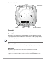
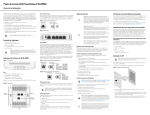
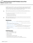
Figure 1 AP-130 Series Access Points (AP-134 Shown)
LED Status Indicators
AP-134_003
134
Antenna Connectors (AP-134 Only)
LEDs
The AP-130 Series access point is equipped with five LEDs that indicate the status of various components of
the device.
PWR: Indicates the whether or not the AP-130 is powered on and its status.
ENET 0: Indicates the status and activity of Ethernet port 0
ENET 1: Indicates the status and activity of Ethernet port 1
11b/g/n: Indicates the status of the 2.4 GHz radio
11a/n: Indicates the status of the 5.0 GHz radio
For more information about the LEDs and their behavior, see Table 3 on page 10.
External Antenna Connectors
The AP-134 is designed for use with external antennas. The AP-135 is equipped with internal antennas. For
more information about antenna types and configurations, visit www.arubanetworks.com.
2
Aruba AP-130 Series Access Point | Installation Guide
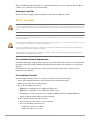
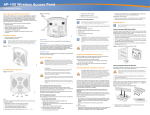
Figure 2 AP-130 Series Rear
Reset Button
AP-134_002
DC Power Socket
CONSOLE
ENET 1
ENET 0
Kensington Security Slot
Console Port
Use the console port to connect to a terminal for direct local management.
Ethernet Ports
AP-130 Series is equipped with two10/100/1000Base-T (RJ-45) auto-sensing, MDI/MDX wired-network
connectivity port. These ports support IEEE 802.3af and 802.3at Power over Ethernet (PoE) compliance,
accepting 56VDC as a standard defined Powered Device (PD) from a Power Sourcing Equipment (PSE)
such as a PoE midspan injector, or network infrastructure that supports PoE.
When operating on 802.3af, only the port connected to power is usable. For example, if the source of power is
connected to ENET 0, ENET 1 will not work.
DC Power Socket
If PoE is not available, an optional Aruba AP AC-DC adapter kit (sold separately) can be used to power the
AP-130 Series.
Reset Button
The reset button can be used to return the AP to factory default settings. To reset the AP:
1. Power off the AP.
2. Press and hold the reset button using a small, narrow object, such as a paperclip.
3. Power-on the AP without releasing the reset button. The power LED will flash within 5 seconds.
4. Release the reset button.
Aruba AP-130 Series Access Point | Installation Guide
3
The power LED will flash again within 15 seconds indicating that the reset is completed. The AP will now
continue to boot with the factory default settings.
Kensington Lock Slot
The AP-130 series is equipped with a Kensington security slot for additional security.
Before You Begin
FCC Statement: Improper termination of access points installed in the United States configured to non-US model
controllers will be in violation of the FCC grant of equipment authorization. Any such willful or intentional violation may
result in a requirement by the FCC for immediate termination of operation and may be subject to forfeiture (47 CFR
1.80).
EU Statement:
Lower power radio LAN product operating in 2.4 GHz and 5 GHz bands. Please refer to the ArubaOS User Guide for
details on restrictions.
Produit réseau local radio basse puissance operant dans la bande fréquence 2.4 GHz et 5 GHz. Merci de vous referrer au ArubaOS User Guide pour les details des restrictions.
Low Power FunkLAN Produkt, das im 2.4 GHz und im 5 GHz Band arbeitet. Weitere Informationen bezlüglich Einschränkungen finden Sie im ArubaOS User Guide.
Apparati Radio LAN a bassa Potenza, operanti a 2.4 GHz e 5 GHz. Fare riferimento alla ArubaOS User Guide per
avere informazioni detagliate sulle restrizioni.
Pre-Installation Network Requirements
After WLAN planning is complete and the appropriate products and their placement have been determined,
the Aruba Controller(s) must be installed and initial setup performed before the Aruba Access Points are
deployed.
For initial setup of the Controller, refer to the ArubaOS Quick Start Guide for the software version
installed on your controller.
Pre-Installation Checklist
Before installing your AP-130 series access point, be sure that you have the following:
For the AP-134: External antennas as specified in the network deployment plan
CAT5 or better UTP cable of required length
One of the following power sources:
4
IEEE 802.3af-compliant Power over Ethernet (PoE) source
IEEE 802.3at-compliant Power over Ethernet+ (PoE+) source
The POE source can be any power source equipment (PSE) controller or midspan PSE device
Aruba 12 VDC AP AC-DC adapter kit (sold separately)
Aruba Controller provisioned on the network:
Layer 2/3 network connectivity to your access point
One of the following network services:
Aruba Discovery Protocol (ADP)
DNS server with an “A” record
Aruba AP-130 Series Access Point | Installation Guide
DHCP Server with vendor-specific options
Summary of the Setup Process
It is important that you verify the items listed under Pre-Installation Checklist before you attempt to set up and
install an AP-130 series AP.
Successful setup of an AP-130 series access point consists of five tasks, which must be performed in this
order:
1. Verify pre-installation connectivity.
2. Identify the specific installation location for each AP.
3. Install each AP.
4. Verify post-installation connectivity.
5. Configure each AP.
Access points are radio transmission devices and as such are subject to governmental regulation. Network
administrators responsible for the configuration and operation of access points must comply with local broadcast
regulations. Specifically, access points must use channel assignments appropriate to the location in which the
access point will be used.
Aruba Networks, in compliance with governmental requirements, has designed the AP-130 series access points so
that only authorized network administrators can change the settings. For more information about AP configuration,
refer to the ArubaOS Quick Start Guide and ArubaOS User Guide.
Verifying Pre-Installation Connectivity
Before you install APs in a network environment, make sure that the APs will be able to locate and connect
to the Controller when powered on.
Specifically, you must verify the following conditions:
When connected to the network, each AP is assigned a valid IP address
APs are able to locate the Controller (Mobility Controller Discovery)
Refer to the ArubaOS Quick Start Guide for instructions on locating and connecting to the Controller.
Identifying Specific Installation Locations
You can mount the AP-130 series access point a ceiling rail (using the included adapter) or on a wall (using
the wall mount adapter, sold separately). Use the AP placement map generated by Aruba’s Airwave Virtual
RF software application to determine the proper installation location(s). Each location should be as close
as possible to the center of the intended coverage area and should be free from obstructions or obvious
sources of interference. These RF absorbers/reflectors/interference sources will impact RF propagation
and should have been accounted for during the planning phase and adjusted for in RF plan.
Unidentified Known RF Absorbers/Reflectors/Interference Sources
Identifying known RF absorbers, reflectors, and interference sources while in the field during the
installation phase is critical. Make sure that these sources are taken into consideration when you attach an
AP to its fixed location.
Aruba AP-130 Series Access Point | Installation Guide
5
RF absorbers include:
Cement/concrete: Old concrete has high levels of water dissipation, which dries out the concrete,
allowing for potential RF propagation. New concrete has high levels of water concentration within the
concrete, blocking RF signals.
Natural Items: Fish tanks, water fountains, ponds, and trees
Brick
RF reflectors include:
Metal Objects: Metal pans between floors, rebar, fire doors, air conditioning/heating ducts, mesh
windows, blinds, chain link fences (depending on aperture size), refrigerators, racks, shelves, and filing
cabinets
Do not place an AP between two air conditioning/heating ducts. Make sure that APs are placed below
ducts to avoid RF disturbances.
RF interference sources include:
6
Microwave ovens and other 2.4 or 5 GHz objects (such as cordless phones)
Lunch rooms and call centers with cordless headsets
Aruba AP-130 Series Access Point | Installation Guide
Installing the AP
Service to all Aruba Networks products should be performed by trained service personnel only.
Using the Ceiling Rail Adapter
The AP130 series ships with two ceiling rail adapters for 9/16” and 15/16” ceiling rails.
Make sure the AP fits securely on the ceiling tile rail when hanging the device from the ceiling, because poor
installation could cause it to fall onto people or equipment.
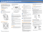
1. Pull the necessary cables through a prepared hole in the ceiling tile near where the AP will be placed.
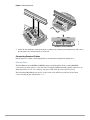
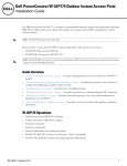
2. Place the adapter against the back of the AP with the adapter at an angle of approximately 30 degrees to
the tabs (see Figure 3).
3. Twist the adapter clockwise until it snaps into place in the tabs (see Figure 3).
AP-130_001
Figure 3 Attaching the Ceiling Rail Adapter
4. If necessary, connect the console cable to the console port on the back of the AP.
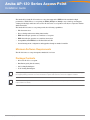
5. Hold the AP next to the ceiling tile rail with the ceiling tile rail mounting slots at approximately a 30degree angle to the ceiling tile rail (see Figure 4). Make sure that any cable slack is above the ceiling tile.
6. Pushing toward the ceiling tile, rotate the AP clockwise until the device clicks into place on the ceiling
tile rail.
Aruba AP-130 Series Access Point | Installation Guide
7
AP-130_002
Figure 4 Mounting the AP
7. On the AP-134, install the external antennas according to the manufacturer’s instructions, and connect
the antennas to the antenna interfaces on the AP.
Connecting Required Cables
Install cables in accordance with all applicable local and national regulations and practices.
Ethernet Ports
The RJ45 Ethernet ports (ENET0 and ENET1) support 10/100/1000Base-T auto-sensing MDI/MDX
connections. Use these ports to connect the AP to a twisted pair Ethernet LAN segment or directly to an
Aruba Controller. Use a 4- or 8-conductor, Category 5 UTP cable up to 100 m (325 feet) long.
The 10/100/1000 Mbps Ethernet ports are on the bottom of the AP. These ports have RJ-45 female
connectors with the pin-outs shown in Table 1.
8
Aruba AP-130 Series Access Point | Installation Guide
Table 1 Ethernet Port Pin-out
Connector
1
2
3
4
5
6
7
8
Pin
Signal
Name
FE
Connection
PoE
1
2
BI_DA+ Bi-directional pair A+
RX+
POE negative
BI_DA–
Bi-directional pair A–
RX–
POE negative
3
BI_DB+ Bi-directional pair B+
TX+
POE positive
4
BI_DC+ Bi-directional pair C+ Spare pair
5
BI_DC–
Bi-directional pair C–
Spare pair
POE positive
6
BI_DB–
Bi-directional pair B–
TX–
POE positive
7
BI_DD+ Bi-directional pair D+ Spare pair
POE negative
8
BI_DB–
POE negative
GE Connection
Bi-directional pair D–
POE positive
Spare pair
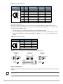
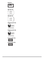
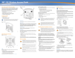
Serial Console Port
The serial console port allows you to connect the AP to a serial terminal or a laptop for direct local
management. This port is an RJ-45 female connector with the pinouts described in Table 2. Connect this
port in one of the following ways:
Connect it directly to a terminal or terminal server using an Ethernet cable.
Use a modular adapter to convert the RJ-45 (female) connector on the AP to a DB-9 (male) connector,
and connect the adapter to a laptop using an RS-232 cable. See Figure 5 for connector details of the
adapter.
Table 2 Console Port Pin-out
Connector
1
2
3
4
5
6
7
8
Pin
Signal Name
Function
3
TXD
Transmit
4
GND
Ground
5
GND
Ground
6
RXD
Receive
Pins not listed are not connected.
Figure 5 RJ-45 (Female) to DB-9 (Male) Modular Adapter Conversion
RJ-45 Female
Pin-Out
1
2
3
TxD
4
5
GND
6
RxD
7
8
Direction
Input
Output
Internal
Connections
RJ-45
TxD
3
4
5
GND
RxD
6
DB-9 Male
Pin-Out
DB-9
2
5
3
9
8
7
6
5
4
3
2
1
Ground
RxD
TxD
Direction
Input
Output
Power Connection
The AP-130 Series has a single 12V DC power jack socket to support powering through an AC-to-DC power
adapter.
If both POE and DC power are available, the AP uses POE even when there is not enough POE voltage available to
power the AP.
Aruba AP-130 Series Access Point | Installation Guide
9
Verifying Post-Installation Connectivity
The integrated LEDs on the AP can be used at this point to verify that the AP is receiving power and
initializing successfully (see Table 3). Refer to the ArubaOS Quick Start Guide for further details on
verifying post-installation network connectivity.
Table 3 AP-130 Series LED Meanings
LED
Color/State
Meaning
PWR
Off
No power to AP
ENET 0
(100/1000 Mbps)
ENET 1
(100/1000 Mbps)
11A/N
11B/G/N
Green steady
Power on, device ready
Green flashing
Device booting, not ready
Red steady
System failed to initialize
Green/Amber off
No link
Green on
1000 Mbps link
Amber on
10/100 Mbps link
Green/amber blinking
Link activity
Green/Amber off
No Link
Green on
1000 Mbps link
Amber on
10/100 Mbps link
Green/amber blinking
Link activity
Off
5 GHz radio disabled
Amber
5 GHz radio enabled in WLAN mode
Green steady
5 GHz radio enabled in 11n mode
Green flashing
5 GHz Air Monitor mode
Off
2.4 GHz radio disabled
Amber
2.4 GHz radio enabled in WLAN mode
Green steady
2.4 GHz radio enabled in 11n mode
Green flashing
2.4 GHz Air Monitor Mode
Configuring the AP-130
AP Provisioning/Reprovisioning
Provisioning parameters are unique to each AP. These local AP parameters are initially configured on the
Controller which are then pushed out to the AP and stored on the AP itself. Aruba recommends that
provisioning settings be configured via the ArubaOS WebUI only. Refer to the ArubaOS User Guide for
complete details.
AP Configuration
Configuration parameters are network or controller specific and are configured and stored on the
Controller. Network configuration settings are pushed out to the AP(s) but remain stored on the Controller.
10
Aruba AP-130 Series Access Point | Installation Guide
Product Specifications
Mechanical
Dimensions (antenna stowed) (HxWxD):
6.69 inches x 6.69 inches x 1.77 inches
17.0 cm x 17.0 cm x 4.5 cm
Weight: 1.68 lbs/760 g
Shipping Dimensions:
11.22 inches x 9.45 inches x 2.76 inches
28.5 cm x 24.0 cm x 7.0 cm
Temperature:
Operating: 0ºC to 50ºC (32ºF to 122ºF)
Operating temperature range is reduced to 0ºC to 40ºC (32ºF to 104ºF) when this AP is used in conjunction with the
Sunny SYS1357-1812 power adapter.
Storage: -40ºC to 70ºC (-40ºF to 158ºF)
Relative Humidity: 5% to 95% non-condensing
Mounting:
Ceiling (with included adapter)
Wall (with adapter, sold separately)
Antennas:
6 integrated antenna elements (AP-135)
3 RP-SMA interfaces for external antennas (AP-134)
Visual Status Indicators (LEDs): See Table 3
Electrical
Ethernet:
2 x 10/100/1000 Base-T auto-sensing Ethernet RJ-45 Interfaces
MDI/MDX
IEEE 802.3 (10Base-T), IEEE 802.3u (100Base-T). IEEE 802.3ab (1000Base-T)
Power over Ethernet (IEEE 802.3at compliant), 48V DC/350mA (see Table 1 on page 9 for pin
configuration)
Power:
12 VDC power interface, supports powering through an AC-to-DC mains electric power adapter
If a power adapter other than the one provided by Aruba Networks is used in the US or Canada, it should be cULus
(NRTL) Listed, with an output rated 12VDC, minimum 1.25A, marked “LPS” or “Class 2,” and suitable for plugging
into a standard power receptacle in the US and Canada. For information on approved power adapters, go to
www.arubanetworks.com/safety_addendum.
POE support on Ethernet ports:
– 802.3at-compliant POE sourcing devices
Aruba AP-130 Series Access Point | Installation Guide
11
Wireless LAN
Network Standards: IEEE 802.11b, IEEE 802.11g, IEEE 802.11a, and IEEE 802.11n
Antenna Type:
Integrated 802.11a/b/g/n omni-directional high-gain antenna
Detachable 802.11a/b/g/n omni-directional high-gain antenna
Antenna Gain (Integrated Antennas):
2.4 – 2.5 GHz (max)
5.180 – 5.825 GHz (max)
Radio Technology:
Orthogonal Frequency Division Multiplexing (OFDM)
Direct Sequence Spread Spectrum (DSSS)
3 x 3 MIMO with up to three spatial streams
Radio Modulation Type:
802.11b - CCK, BPSK, QPSK
802.11a/g/n - CCK, BPSK, QPSK,16-QAM, 64-QAM
Media Access Control: CSMA/CA with ACK
Supported Frequency Bands 2.4GHz:
2.400 ~ 2.4835GHz (Global), channels country specific
Supported Frequency Bands 5GHz:
5.150 ~ 5.250GHz (low band), country-specific
5.250 ~ 5.350GHz (mid band), country-specific
5.470 ~ 5.725GHz (Europe), country-specific
5.725 ~ 5.850GHz GHz (high band), country-specific
Data Rates:
802.11b - 1, 2, 5.5, 11 Mbps per channel
802.11g - 6, 9, 12, 18, 24, 36, 48 and 54 Mbps per channel
802.11a - 6, 9, 12, 18, 24, 36, 48 and 54 Mbps per channel
802.11n - Data rate MCS0 – MCS23 (from 6.5 Mbps to 450 Mbps)
Proper Disposal of Aruba Equipment
For the most current information about Global Environmental Compliance and Aruba products, see our
website at www.arubanetworks.com.
Waste of Electrical and Electronic Equipment
Aruba products at end of life are subject to separate collection and treatment in the EU
Member States, Norway, and Switzerland and therefore are marked with the symbol
shown at the left (crossed-out wheelie bin). The treatment applied at end of life of these
products in these countries shall comply with the applicable national laws of countries
implementing Directive 2002/96EC on Waste of Electrical and Electronic Equipment
(WEEE).
12
Aruba AP-130 Series Access Point | Installation Guide
European Union RoHS
Aruba products also comply with the EU Restriction of Hazardous Substances
Directive 2002/95/EC (RoHS). EU RoHS restricts the use of specific hazardous
materials in the manufacture of electrical and electronic equipment. Specifically,
restricted materials under the RoHS Directive are Lead (including Solder used in printed circuit
assemblies), Cadmium, Mercury, Hexavalent Chromium, and Bromine. Some Aruba products are subject to
the exemptions listed in RoHS Directive Annex 7 (Lead in solder used in printed circuit assemblies).
Products and packaging will be marked with the “RoHS” label shown at the left indicating conformance to
this Directive.
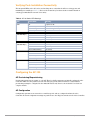
China RoHS
10
Aruba products also comply with China environmental declaration requirements and are
labeled with the “EFUP 10” label shown at the left.
Safety and Regulatory Compliance
Aruba Networks provides a multi-language document that contains country-specific restrictions and
additional safety and regulatory information for all Aruba access points. This document can be viewed or
downloaded from the following location: www.arubanetworks.com/safety_addendum
FCC Class B Part 15
This device complies with Part 15 of the Federal Communications Commission (FCC) Rules. Operation is
subject to the following two conditions:
This device may not cause harmful interference.
This device must accept any interference received, including interference that may cause undesired
operation.
Changes or modifications to this unit not expressly approved by the party responsible for compliance could void
the user’s authority to operate this equipment.
Aruba AP-130 Series Access Point | Installation Guide
13
This equipment has been tested and found to comply with the limits for a Class B digital device, pursuant to
Part 15 of the FCC Rules. This equipment generates, uses and can radiate radio frequency energy and, if not
installed and used in accordance with the manufacturer’s instructions, may cause interference harmful to
radio communications.
If this equipment does cause interference, which can be determined by turning the equipment off and on,
the user is encouraged to try to correct the interference by one or more of the following measures:
Reorient or relocate the receiving antenna.
Increase the separation between the equipment and receiver.
Connect the equipment to an outlet on a circuit different from that to which the receiver is connected.
Consult the dealer or an experienced radio or TV technician for help.
Complies with the Class B limits for radio noise emissions as set out in the interference-causing equipment
standard entitled “Digital Apparatus,” ICES-003 of Industry Canada.
Cet apareil numerique de la classe B respecte toutes les exigencies du Reglement sur le materiel brouilleur
du Canada.
EU Regulatory Conformance
This product is CE marked according to the provisions of the R & TTE Directive (99/5/EC) - CE 2280(!){! In
circle}. Aruba Networks Inc., hereby declares that this AP-134 and AP-135 device models are in compliance
with the essential requirements and other relevant provisions of Directive 1999/5/EC. CE 2280(!)
The Declaration of Conformity made under Directive 1999/5/EC is available for viewing at the following
location in the EU community.
RF Radiation Exposure Statement: This equipment complies with FCC RF radiation exposure limits. This
equipment should be installed and operated with a minimum distance of 7.87 inches (20 cm) between the radiator
and your body for 2.4 GHz and 5 GHz operations. This transmitter must not be co-located or operating in
conjunction with any other antenna or transmitter. When operated in the 5.15 to 5.25 GHz frequency range, this
device is restricted to indoor use to reduce the potential for harmful interference with co-channel Mobile Satellite
Systems.
GS Statement
This device is not intended for use in the direct field of view at visual display workplaces. To avoid
incommoding reflexions at visual display workplaces, this device must not be placed in the direct field of
view.
Medical
1. Equipment not suitable for use in the presence of flammable mixture.
2. End product system, including power supply, must be evaluated to IEC 60601-1-1 and IEC 60601-1 by the
end user.
3. Wipe with a dry cloth, no any other maintenance required.
4. No serviceable parts and the unit must be sent back to the manufacturer for repair.
14
Aruba AP-130 Series Access Point | Installation Guide
Singapore
200202320G
UAE (AP-134)
TRA
REGISTERED No:
ER0072980/11
DEALER No:
DA0039425/10
UAE (AP-135
TRA
REGISTERED No:
ER0072981/11
DEALER No:
DA0039425/10
Philippines (AP-134)
Type-Approval No.
ESD-CPE-1105695C
Philippines (AP-135)
Type-Approval No.
ESD-CPE-1105696C
Indonesia (AP-134)
22099/SDPPI/2011
1912
Indonesia (AP-135)
22163/SDPPI/2011
1912
Aruba AP-130 Series Access Point | Installation Guide
15
For More Information
To contact Aruba Networks, refer to the information below:
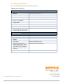
Table 4 Contact Information
Web Site Support
Main Site
http://www.arubanetworks.com
Support Site
https://support.arubanetworks.com
Software Licensing Site
https://licensing.arubanetworks.com/login.php
Wireless Security Incident
Response Team (WSIRT)
http://www.arubanetworks.com/support/wsirt.php
Support Emails
Americas and APAC
[email protected]
EMEA
[email protected]
WSIRT Email
Please email details of any security
problem found in an Aruba product.
[email protected]
Telephone Numbers
Aruba Corporate
+1 (408) 227-4500
FAX
+1 (408) 227-4550
Support
United States
800-WI-FI-LAN (800-943-4526)
Universal Free Phone Service
Number (UIFN): Australia, Canada,
China, France, Germany, Hong
Kong, Ireland, Israel, Japan, Korea,
Singapore, South Africa, Taiwan,
and the UK
+800-4WIFI-LAN (+800-49434-526)
All other countries
+1 (408) 754-1200
www.arubanetworks.com
1344 Crossman Avenue
Sunnyvale, California 94089
© 2012 Aruba Networks, Inc. All rights reserved.
16
Phone: 408.227.4500
Fax 408.227.4550
Aruba AP-130 Series Access Point | Installation Guide