1
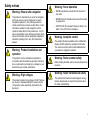
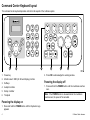
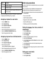
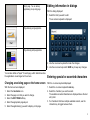
G-Series
system
Quick reference
ENGLISH
Document number: 86138-1
Date: 11-2010
Safety notices
Warning: Ensure safe navigation
This product is intended only as an aid to navigation
and must never be used in preference to sound
navigational judgment. Only official government
charts and notices to mariners contain all the current
information needed for safe navigation, and the
captain is responsible for their prudent use. It is the
user’s responsibility to use official government charts,
notices to mariners, caution and proper navigational
skill when operating this or any other Raymarine
product.
Warning: Product installation and
operation
This product must be installed and operated in
accordance with the instructions provided. Failure to
do so could result in personal injury, damage to your
boat and/or poor product performance.
Warning: High voltages
This product contains high voltages. Do NOT remove
any covers or otherwise attempt to access internal
components, unless specifically instructed in this
document.
Warning: Sonar operation
• NEVER operate the sounder with the boat out of
the water.
• NEVER touch the transducer face when the sounder
is powered on.
• SWITCH OFF the sounder if divers are likely to be
within 7.6 m (25 ft) of the transducer.
Warning: Autopilot control
The autopilot functions available on the multifunction
display do NOT replace the autopilot control head.
You must have a pilot control head installed before
you enable or engage the autopilot.
Warning: Radar scanner safety
Before rotating the radar scanner, ensure all personnel
are clear.
Warning: Radar transmission safety
The radar scanner transmits electromagnetic energy.
Ensure all personnel are clear of the scanner when
the radar is transmitting.
3
Command Center Keyboard layout
The command center keyboard provides controls for all aspects of the G-Series system.
1
3
DEF
4
5
6
GHI
JKL
MNO
WPTS
PAGE
MENU
MOB
OUT
RANGE
ENTER
1
2
ABC
7
8
9
PQRS
TUV
WXYZ
.
0
2
IN
ACTIVE
DODGE
3
DATA
STANDBY
4
PILOT
OK
5
CANCEL
6
D10547-2
1. Power key
2. Press OK to acknowledge the warning window.
2. Monitor select / OSD (On Screen Display) controls
3. Softkeys
Powering the display off
4. Autopilot controls
1. Press and hold the POWER button until the countdown reaches
zero.
5. Rotary controller
6. Trackpad
Note: If the POWER button is released before the countdown
reaches zero, the power off is cancelled.
Powering the display on
1. Press and hold the POWER button until the Raymarine logo
appears.
4
G-Series Quick reference
Nav stations
A Nav Station is a grouping of up to 4 monitors and a keyboard,
enabling you to adjust the brightness and power for all monitors
from the same keyboard.
Each Nav Station includes at least 1 monitor and at least 1 keyboard:
Monitors — Up to 2 monitors can be connected to each GPM
processor in your system.
Keyboards — A keyboard can be assigned to a single monitor, a
Nav Station, or all monitors in your system, but can only control 1
monitor at a time. You can select which monitor you want to control
from the keyboard. When a keyboard is associated with a monitor,
this provides full control of the system.
2
1
3
ABC
4
DEF
5
GHI
6
JKL
WPTS
PAGE
MNO
MENU
MOB
OUT
RANGE
ENTER
7
8
PQRS
TUV
9
IN
ACTIVE
WXYZ
0
1
DODGE
DATA
PILOT
STANDBY
OK
CANCEL
The following diagram illustrates a typical Nav Station arrangement:
1
2
ABC
4
GHI
ENTER
2
5
JKL
3
DEF
6
MNO
WPTS
PAGE
MENU
MOB
OUT
RANGE
7
8
PQRS
TUV
0
9
WXYZ
IN
ACTIVE
DODGE
DATA
STANDBY
PILOT
OK
CANCEL
3
D10239-2
5
Number
Description
1
Nav Station 1 (flybridge)
2
Nav Station 2 (bridge)
3
Below-decks components (for example, GPM processor unit,
GVM video module)
Refer to the installation instructions for information on planning and
configuring the Nav Station(s) for your system.
Initial setup procedures
A number of tasks should be completed before you use your system
for the first time.
Once your system has been installed and commissioned (see
Installation instructions), Raymarine recommends that you:
• Set the language, the date and time format and preferred units
of measurement.
• Set your vessel details.
• Adjust the display brightness.
Assigning a keyboard to a nav station
• Designate the data master (master GPM).
1.
2.
3.
4.
5.
6.
7.
• Select the GPS data source.
Press the MENU button.
Select System Setup.
Select System Configuration.
Select Assign Keyboards.
Select the appropriate keyboard from the list.
Select the ASSIGN TO NAVSTATION softkey.
Select the appropriate Nav Station.
Assigning a keyboard to an individual monitor
1.
2.
3.
4.
Press the MENU button.
Select System Setup.
Select System Configuration.
Select Assign Keyboards.
A list of available keyboards is displayed.
5. Select the appropriate keyboard from the list.
6. Select the ASSIGN TO MONITOR softkey.
7. Select the appropriate monitor.
• Familiarize yourself with the Simulator Mode.
Setting the language, time / date, and units of
measurement
1.
2.
3.
4.
5.
6.
Press the MENU button.
Select System Setup.
Select Language.
Select the appropriate language from the list.
Select Time / Date Setup.
Use the Date Format and Time Format menu items to adjust
the date and time.
7. Use the Cancel button to return to the System Setup menu.
8. Select Units Setup.
9. Make the appropriate changes using the menu items in the Units
Setup Menu.
Setting your vessel details
1. Press the MENU button.
2. Select System Setup.
6
G-Series Quick reference
3. Select Boat Details.
4. Change the Safe Depth, Safe Height and Safe Width settings
as appropriate for your vessel.
Note: The settings you specify for your vessel details are
essential for the accurate operation of the collision alarm. You
must specify vessel detail settings that are appropriate for safe
navigation.
Note: The collision alarm uses data from the GPS antenna in its
calculations. Therefore the values you specify for your vessel
detail settings must reflect the actual position of the GPS antenna
on your vessel. For example, the "Safe Width" setting is actually
the diameter either side of the GPS antenna, so if you have a
vessel 4 meters wide and you enter a minimum “Safe Width" of 4
meters, this is actually providing a collision zone of only 2 meters
either side of the GPS antenna. If the GPS antenna is mounted
on the port side of the vessel and you specified a Safe Width of 4
meters, you would be leaving 2 meters of the hull uncovered by
the collision zone.
Adjusting the monitor brightness
On the G-Series keyboard:
1. Press the POWER button on the keyboard once.
The backlight level control is displayed on the monitor.
2. Using the rotary control, adjust the brightness level as
appropriate.
3. To adjust the brightness for a monitor assigned to a different Nav
Station, press the rotary control once and select the appropriate
Nav Station from the list.
Data master (master GPM)
If your system features more than one GPM processor unit you must
designate one GPM processor as the data master (master GPM).
If the data master has not already been designated as part of the
installation and commissioning process it must be done as part of
the initial setup.
The data master handles all the data from the various marine
electronics installed around your vessel. The data master receives
data from SeaTalk and SeaTalkng and transmits it to the relevant
components of the G-Series system via the SeaTalkhs network.
For example the system may require heading information from the
autopilot and GPS systems, usually received through a SeaTalkng or
NMEA connection. The data master is the GPM processor to which
the SeaTalk, NMEA and any other data connections are made, it
then bridges the data to the SeaTalkhs network and any compatible
repeat displays. Information shared by the data master includes:
• Cartography
• Routes and waypoints
• Radar
• Sonar
• Data received from the autopilot, instruments, the engine and
other external sources.
Note: The GPM processor that you choose to be the master
GPM must be the unit to which the SeaTalk and SeaTalkng buses
are physically connected.
Designating the data master (master GPM)
1. Press the MENU button.
2. Select the System Configuration menu item.
7
3. Select the Set Master GPM option.
A list of available connected GPM processors is displayed, with
serial numbers. The Local GPM refers to the GPM to which the
monitor is physically connected.
4. Select the processor you want to designate as the data master.
5. Select the SET AS MASTER softkey.
Note: If you are unsure of which GPM to select use the
DISCOVER GPM softkey, which shows a message on every
monitor identifying the GPM to which it is connected.
Simulator mode
The Simulator mode enables you to practice operating your display
without data from a GPS antenna, radar scanner, AIS unit, or
fishfinder.
The simulator mode is switched on/off in the System Setup Menu.
You can also adjust the vessel speed in simulator mode. This is
useful for quickly moving to different areas of the chart, for example.
Note: Raymarine recommends that you do NOT use the
simulator mode whilst navigating.
Note: The simulator will NOT display any real data, including any
safety messages (such as those received from AIS units).
Note: Any system settings made whilst in Simulator mode are not
transmitted via SeaTalk to other equipment.
3. Select the Simulator item, and change its value to On.
Applications
Chart application — provides a 2D
or 3D graphical view of your charts to
help you navigate. Waypoint, route, and
track functions enable you to navigate
to a specific location, build and navigate
routes, or record where you’ve been.
Upgrade your charts using chart cards to
enjoy higher levels of detail and 3D views.
Fishfinder application — with a suitable
Digital Sounder Module (DSM) and
transducer, you can use the fishfinder
application to help you accurately
distinguish between different sizes of
fish, bottom structure, and underwater
obstacles. You can also view sea depth
and temperature data, and mark points of
interest, such as fishing spots or wrecks.
Radar application — with a suitable radar
scanner, you can use the radar application
to track targets and measure distances
and bearings. A number of automatic gain
presets and color modes are provided to
help you get the best performance from
your radar scanner.
Enabling the simulator mode
1. Press Menu.
2. Select the System Setup menu.
8
G-Series Quick reference
Engine application — enables you to
view engine information in the form of
gauges and digital data, from up to 3
compatible engines.
Weather application — (North America
only). With a suitable weather receiver
connected to your system, the weather
application overlays historical, live, and
forecasted weather graphics on a world
map.
Data application — view system and
instrument data on your multifunction
display, for a range of compatible
instruments.
Video application — view a video or
camera source on your multifunction
display. With the appropriate optional
accessories, you can connect additional
video sources and switch between them.
Course Deviation Indicator (CDI)
application — provides a graphical
representation of your vessel’s course in a
“rolling road” format, along with navigation
data.
Home screen overview
The home screen provides a central point of access to your system’s
range of applications.
It also provides quick access to your waypoints, routes, and tracks.
Sirius audio application — (North
America only). Use your multifunction
display to control a connected Sirius
Satellite Radio receiver.
Press the PAGE button at any time to access the home screen.
The home screen consists of a number of application "pages", each
represented by an icon. Applications can be started by selecting
the relevant page icon.
Use the MORE softkeys to scroll the home screen and access
additional application pages.
9
2
1
3
4
Screen item
Description
3
Customize — select this icon to configure application
pages.
4
More — select this softkey to scroll the home screen and
access additional application pages.
Pages
Pages are used on your multifunction display to show applications.
Pages are displayed and accessed on the home screen. Each page
can display between 1 and 4 applications.
Any page on the home screen can be customized, enabling you to
group your applications into different pages, each designed for a
specific purpose. For example, you could have a page that includes
the chart and fishfinder applications, suitable for fishing, and another
page that includes the chart and data applications, which would
be suitable for general sailing.
Screen item
Description
1
Page — each icon represents a page. A page can display
up to 4 applications simultaneously.
2
My Routes / My Tracks / My Waypoints — these icons
enable you to centrally manage your lists of routes, tracks,
and waypoints.
10
G-Series Quick reference
Empty page. You can add any
application(s) to any empty page.
Editing information in dialogs
With the dialog displayed:
1. Select the field you want to edit.
The on-screen keyboard is displayed:
Page featuring a single application.
Page featuring multiple applications.
2. Use the on-screen keyboard to make the changes.
3. Use the on-screen keyboard’s SAVE key to keep any changes.
You can also define a "layout" for each page, which determines how
the applications are arranged on the screen.
Changing an existing page on the home screen
With the home screen displayed:
1. Select the Customize icon.
2. Select the page icon that you want to change.
3. Select the EDIT PAGE softkey.
4. Select the appropriate page layout.
5. Select the application(s) you want to display on the page.
Entering special or accented characters
With the on-screen keyboard displayed:
1. Select the on-screen keyboard’s àèò key.
2. Select the character you want to accent.
The available accented characters are displayed above the text
entry field.
3. For characters that have multiple available accents, use the
character key to toggle between them.
11
4. Select the àèò key to enter the character.
Alarms
Alarms alert you to a situation or hazard requiring your attention.
You can set up alarms to alert you to certain conditions, such as
collision warnings and temperature limits.
Alarms are raised by system functions, and also external equipment
connected to your multifunction display.
When an alarm sounds, a message dialog is displayed on your
multifunction display, and any networked displays. The dialog
explains the reason for the alarm.
You can configure the behaviour of the following system and
application alarms using the Alarms Setup Menu:
• System alarms.
• Navigation alarms.
• Radar alarms.
• Fishfinder alarms.
• AIS alarms.
Man overboard
If you lose a person or object overboard, you can use the Man
Overboard (MOB) function to mark the position.
The MOB function is available at all times, regardless of which
application is running.
When MOB is activated, an alert message appears on-screen, and
an emergency waypoint is created. A bearing to the waypoint is
also provided. The alert and emergency waypoint also appear on
any networked displays at the same time.
12
Activating the man overboard function
1. Press and hold the WPTS/MOB button for 3 seconds.
The normal chart application is reset to the same settings that
it had before the MOB alarm was raised.
Note: To obtain a MOB position, your multifunction display must
have a GPS position fix.
Cancelling a MOB alarm
1. Press and hold the WPTS/MOB button for four seconds.
Once the MOB alarm is cleared:
• the chart application motion mode is reset.
• the databar mode is reset.
• GOTO and route functions are restored.
G-Series Quick reference
www.ra ym a rin e .c o m