1
Gas Hobs
INSTRUCTION BOOKLET
Mod. EHG 65 - EHG 66
35678-2902
AU
Important Safety Information
You MUST read hese warnings carefully before installing or using the hob. If you need assistance, contact
our local Customer Care Department
Installation
l
l
l
l
l
•
•
This hob must be installed by qualified personnel,
according to the manufacturers instructions and to
the relevant Australian Standards.
Any gas installation must be carried out by a registered
installer.
Remove all packaging before using the hob.
Ensure that the gas and electrical supply complies
with the type stated on the rating plate, located near
the gas supply pipe.
Do not attempt to modify the hob in any way.
The appliance must be installed at a minimum distance
of cm.50 from curtains or other combustible material.
Where this appliance is installed in marine craft or in
caravans, it shall not be used as a space heater.
l
l
•
Service
l
l
l
l
l
This hob is designed to be operated by adults. Do
not allow children to play near or with the hob.
The hob gets hot when it is in use.
Children should be kept away until it has cooled.
Children can also injure themselves by pulling pans
or pots off the hob.
During Use
l
l
l
l
l
l
l
l
2
This hob is intended for domestic cooking only. It is
not designed for commercial or industrial purposes.
When in use a gas cooking appliance will produce
heat and moisture in the room in which it has been
installed. Ensure there is a continuous air supply,
keeping air vents in good condition or installing a
cooker hood with a venting hose.
When using the hob for a long period of time, the
ventilation should be improved, by opening a window
or increasing the extractor speed.
Do not use this hob if it is in contact with water.
Do not operate the hob with wet hands.
Ensure the control knobs are in the OFF position
when not in use.
When using other electrical appliances, ensure the
cable does not come into contact with the hot
surfaces of the cooking appliance.
Unstable or misshapen pans should not be used on
the hob as unstable pans can cause an accident by
tipping or spillage.
Never leave the hob unattended when cooking with
oil and fats.
This hob should only be repaired or serviced by an
authorised Service Engineer and only genuine
approved spare parts should be used.
Environmental Information
l
Child Safety
Never use plastic or aluminium foil dishes on the hob.
Perishable food, plastic items and aerosols may be
affected by heat and should not be stored above or
below the hob unit.
Do not spray aerosols in the vicinity of this appliance
while it is in operation.
l
After installation, please dispose of the packaging
with due regard to safety and the environment.
When disposing of an old appliance, make it unusable,
by cutting off the cable.
Keep this instruction book for future reference
and ensure it is passed on to any new owner.
Guide to Use the instructions
The following symbols will be found in the text to guide
you throughout the Instructions:
Safety Instructions
F
Step by step instructions for an operation
Hints and Tips
Environmental Information
Contents
For the Installer
For the User
Important Safety Information
2
Instructions for the Installer
6
Description of the Hob
3
Important safety requirements
6
Operation
4
Installation
7
Maintenance and Cleaning
4
Electrical connections
8
Something Not Working?
5
Adaptation to different types of gas
8
Building In
9
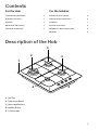
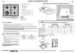
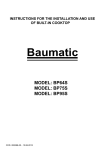
Description of the Hob
3
2
3
1
4
5
1. Hob Top
2. Triple crown Burner
3. Semi-rapid Burners
4. Auxiliary Burner
5. Control knobs
3
Operation
Hob Burners
F
To light a burner:
l
push in the relevant control knob and turn it
anticlockwise to maximum position;
l
Mod. EHG 66: upon ignition, keep the knob pushed
down about 5 seconds. This will allow the
"thermocouple" (Fig. 1 - letter D) to be heated and
the safety device to be switched off, otherwise the
gas supply would be interrupted;
l
then adjust the flame as required.
If the burner does not ignite, turn the control knob to
zero, and try again.
To ensure maximum burner efficiency, you should only
use pots and pans with a flat bottom fitting the size of
the burner used (see table).
Burner
Large (triple-crown)
Medium (semi-rapid)
Small (Auxiliary)
minimum
diameter
180 mm.
120 mm.
80 mm.
maximum
diameter
260 mm.
220 mm.
160 mm.
If you use a saucepan which is smaller than the
recommended size, the flame will spread beyond
the bottom of the vessel, causing the handle to
overheat.
As soon as a liquid starts boiling, turn down the
flame so that it will barely keep the liquid
simmering.
Take care when frying food in hot oil or fat, as
the overheated splashes could easily ignite.
If the control knobs become difficult to turn, please
contact your local Service Centre.
Using the Wok Stand
A wok stand is provided to enable you to use a round
bottomed wok on the hob. The wok stand must only be
used on the triple crown burner, and should not be used
with any other type of wok or pan.
When fitting the wok stand, ensure the recesses in the
frame fit securely onto the bars of the pan supports, as
shown in the diagram.
4
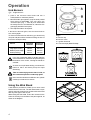
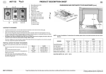
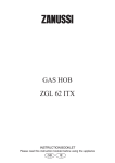
Fig. 1
A - Burner cap
B - Burner crown
C - Ignition electrode
D - Thermocouple (Mod. EHG 66)
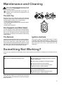
Maintenance and Cleaning
Before any maintenance or cleaning can be carried
out, you must DISCONNECT the hob from the
electricity supply.
The hob is best cleaned whilst it is still warm, as
spillage can be removed more easily than if it is
left to cool.
The Hob Top
Regularly wipe over the hob top using a soft cloth well
wrung out in warm water to which a little washing up liquid
has been added. Avoid the use of the following:
- household detergent and bleaches;
- impregnated pads unsuitable for non-stick saucepans;
- steel wool pads;
- bath/sink stain removers.
Pan Supports and Wok Stand
The pan supports and the Wok Stand are dishwasher
proof. If washing them by hand, take care when drying
them as the enamelling process occasionally leaves
rough edges. If necessay, remove stubborn stains using
a paste cleaner.
The Burners
Ignition electrode
The burner caps and crowns can be removed for cleaning.
Wash the burner caps and crowns using hot soapy water,
and remove marks with a mild paste cleaner. A well
moistened soap impregnated steel wool pad can be used
with caution, if the marks are particularly difficult to remove.
After cleaning, be sure to wipe dry with a soft cloth.
The electric ignition is obtained through a ceramic
"electrode" and a metal electrode (Fig. 1 - letter C). Keep
these components very clean, to avoid lighting difficulties,
and check that the burner crown holes are not
obstructed.
Something Not Working?
If the hob is not working correctly, please carry out the following checks before contacting your local Service Force
Centre.
SYMPTOM
n There is no spark when lighting the gas
SOLUTION
u Check that the unit is plugged in and the electrical
supply is switched on
u Check that the RCCB has not tripped (if fitted)
u Check the mains fuse has not blown
u Check the burner cap and crown have been
replaced correctly, e.g. after cleaning.
n The gas ring burns unevenly
u Check the main jet is not blocked and the burner
crown is clear of food particles.
u Check the burner cap and crown have been
replaced correctly, e.g. after cleaning.
If after all these checks, your hob still does not operate
correctly, contact your local Service Force Centre (see
pages 10 and 11)
5
Instructions for the Installer
Engineers technical data
SUPPLY CONNECTIONS
Gas:
RC 1/2 inch (1/2 inch male) Rear right hand corner
OVERALL DIMENSIONS
Width:
580 mm.
Depth:
500 mm.
Electric:
230-240V 50Hz supply
CUT OUT DIMENSIONS
Width:
550 mm.
Depth:
470 mm.
TYPE
OF BURNER
TYPE
OF GAS
APPLIANCE GAS SUPPLY:
Natural gas 1.0 kPa - Universal LPG 2.75 kPa
NOZZLE
NOMINAL
MARKS
GAS
1/100 mm CONSUMPTION
MJ/h
NOMINAL
PRESSURE
kPa
NATURAL
GAS
Triple Crown (wok)
Semi-rapid (medium)
Auxiliary (small)
1.57
1.11
0.89
13.00
6.80
3.80
1.00
U-LPG
Triple Crown (wok)
Semi-rapid (medium)
Auxiliary (small)
0.97
0.71
0.55
13.00
6.30
3.80
2.75
Burner
Dia. Tap By-pass
1/100 mm
Auxiliary
28
Semi-rapid
35
Triple crown
42
Aeration adjustment none
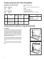
Important safety requirements
Location
Choose a location free of draughts and open doors and
clear of combustible materials or other fire hazards such
as curtains, etc. The location should ensure convenience
of operation and service. Any adjacent wall surface
situated within 200mm from the edge of any hob burner
and above the height of the hob must be a suitable noncombustible material for a height of 150 mm for the entire
depth and width of the cooker.
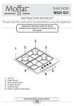
FITTING THE GAS HOB
WITHOUT A COOKER HOOD ABOVE
700 mm
400 mm
55
50 m
mm
m
100
400 mm
mm
Any combustible material above the hotplate must be at
least 650 mm above the top of the hob and no
construction shall be within 450 mm above the top of the
burner.
50 m
m
FO 0812
FITTING THE GAS HOB
WITH A COOKER HOOD ABOVE
600 mm
A minimum distance of 100 mm. must be left between
the side edges of the hob and any adjacent cabinets or
walls.
650 mm
400 mm
55
50 m
mm
m
100
400 mm
mm
50 m
m
FO 0813
6
Installation
Important
This appliance must be installed by qualified
personnel.
The installer shall verify the satisfactory operation
of the ignition system on all burners both
individually and in combination.
The manufacturer will not accept liability, should
the above instructions or any of the other safety
instructions incorporated in this book be ignored.
Regulations
This appliance shall be installed in accordance with the
manufacturers installation instructions, local gas fitting
regulations, municipal building codes, AS5601 (AG601)
and any other relevant statutory regulations.
Data label
The data label is located on the bottom of the appliance.
This appliance is suitable for Natural or Universal LPG.
Ensure that the gas supply matches the data label. A
duplicate of the data label is supplied in the packaging of
the user manual and must be attached to readily
accessible adjacent surfaces of the appliances.
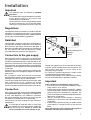
Connection to the gas supply
Gas connection must be carried out in conformity with
the regulations in force. The appliance leaves the factory
tested and regulated for the type of gas indicated on the
plate which is situated in the lower position near the gas
connection tube. Ascertain that the type of gas with which
the appliance will be supplied is the same as that indicated
on the plate.
If different carry out all the operations according to the
indications cited in the paragraph adaption to different
types of gas.
For a maximum output and minimum consumption
ascertain that the pressure of the gas used has the values
indicated in the table of burner characteristics.
The joint is mounted on the intake area of the pipe, fitted
with a filleted nut G 1/2", between the sealing
components. Screw the parts without forcing, turn the
joint in the direction required and then tighten everything.
Connection
Carry out the connection to the gas plant only by means
of a rigid metallic pipe conforming to the regulations
in force. This appliance is not suitable for connection
with a hose assembly. The joint for the entry of gas into
the appliance is threaded R 1/2" (male thread).
Carry out the connection avoiding any type of stress on
the appliance.
It is important to install the elbow correctly, with
the shoulder on the end of the thread, fitted to the
hob connecting pipe. Failure to ensure the
correct assembly will cause leakage of gas.
FO 0814
FO 0264
A) End of shaft with nut
B) Washer
C) Elbow
Natural gas appliances must be fitted with a pressure
regulator and be installed at the inlet connection. The
gas pressure must then be set as a part of the
commissioning procedures.
For U-LPG the pressure adjustment is made via the
regulator fitted at the domestic cylinder.
The natural gas regulator and U-LPG pressure test point
must be accessible with the appliance installed.
Important
Upon completion of installation, always check:
l
that all the joints are completely sealed by using a
soapy solution, never a flame;
l
that the gas pressure has been regulated to 1.00kPa
for Natural Gas and 2.75kPa for Universal-LPG. The
pressure test point is located on the regulator. The
pressure should be measured and adjusted with the
Wok burner on high flame;
l
that the automatic ignition system is operating
satisfactory on all burners, both individually and in
combination;
l
that the burners operate correctly, are stable, without
yellow tipping or excessive noise on high and low
flame.
Then demonstrate to the customer the appliance
operation and leave these instructions.
7
Electrical connections
The appliance is designed to be connected to 230-240 V
monophase electricity supply.
The connection must be carried out in compliance with
the laws and regulations in force.
Before the appliance is connected:
1) check that the main fuse and the domestic installation
can support the load (see the rating label);
2) check that the power supply is properly earthed in
compliance with the current rules;
3) check the socket or the double pole switch used for
the electrical connection can be easily reached with
the appliance built in the furniture unit.
The appliance is supplied with a connection cable provided
with a plug, able to support the load marked on the
identification plate. The plug has to be fitted in a proper
socket.
If connecting the appliance directly to the electric system,
it is necessary that you install a double pole switch
between the appliance and the electricity supply, with a
minimum gap of 3 mm. between the switch contacts
and of a type suitable for the required load in compliance
with the current rules.
The connection cable has to be placed in order that, in
each part, it cannot reach a temperature 50 °C higher
than the room temperature.
The brown coloured phase cable (fitted in the terminal
block contact marked with "L") must always be connected
to the network phase.
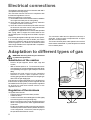
Adaptation to different types of gas
WARNING: Servicing shall only be carried out
by authorised personnel.
Substitution of the nozzles
-
Remove all pan supports, burner caps, rings and
crowns;
- With a tubular spanner no. 7 unscrew and remove
(see diagram) the nozzles substituting them with those
corresponding to the type of gas used (see Technical
data);
- Remount the parts carrying out the operations
described in reverse. Upon completion remove
existing gas type label and stick the relevant gas type
label near the gas supply pipe.
If the pressure of gas used is different (or variable) from
that foreseen an appropriate pressure regulator should
be installed on the entry tube. In case pressure regulators
for U-LPG are used these should conform to the
regulations in force.
FO 0392
Regulation of the minimum
To regulate the minimum:
- bring the tap to the minimum flame position.
- extract the knob.
- in case of conversion from natural gas to U-LPG, tightly
screw the by-pass screw (see diagram);
- when converting from U-LPG to natural gas unscrew
about ½ turn by-pass screw, until a regular small flame
is reached.
Finally check that by quickly turning the tap from the
maximum position to the minimum position the burner
is not extinguished; remount the parts carrying out
the operations described in reverse.
8
By pass screw
in.
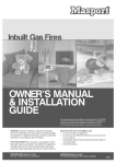
Rectangular cut-out size for hob
55 m
Cut Out Size
470
The dimensions of the cut-out are given in the diagram.
117
20
R 60
30
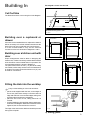
Building In
550
Dimensions are given in mm.
FO 2098
Building over a cupboard or
drawer
Proper arrangements must be taken in designing the
furniture unit, in order to avoid any contact with the bottom
of the hob which can be heated when it is operated. The
recommended solution is shown in diagram 3.
The panel fitted under the hob ("a") should be easily
removable to allow easy access if technical assistance
is needed. The space behind the kitchen unit ("b") can
be used for connections.
2
ON/OFF SWITCH
FLEX
OUTLET
FLEX
OUTLET
FO 0763
3
30
Building over a kitchen unit with
door
1
a
60
20 min
If the hob is to be installed above a cupboard or drawer it
will be necessary to fit a heat resistant board below the
base of the hob on the underside of the work surface.
It is also recommended to carry out the electrical
connection to the hob as shown in diagrams 1 and 2.
ON/OFF SWITCH
b
Fitting the Hob into the worktop
F
Carry out the building in of the hob as follows:
FO 1013
put the seals supplied with the hob, on the edges of
the cut out: place them exactly on the front and rear
edge and at 50 mm. from the side edges, taking care
that the seals meet without overlapping;
place the hob in the cut out, taking care that it is
centred;
fix the hob with the relevant fixing clamps and screws,
as shown in the diagram. When the screws have been
tightened, the excess seal can be removed.
The edge of the hob forms a double seal which prevents
the ingress of liquids.
a
FO 0199
a) Sealing gasket
9
ELECTROLUX WARRANTY AUSTRALIA
Nothing in this warranty, limits any rights you may have under the Trade Practices Act or any other Commonwealth or
State legislation. Such rights cannot be changed by the conditions in this warranty.
Subject to the conditions below, this appliance is warranted by Electrolux Home Products Pty. Ltd. A.B.N. 51 004 762
341, (the Company), to be free from defects in materials and workmanship for a period of 24 months following the
date of purchase (the Warranty Period).
Conditions of the warranty:
1 During the Warranty Period the Company, or its service agent, will only pay the cost of repairing or replacing all
Company parts on your appliance which the Company finds to be defective.
2 The Company will decide if there are any defects in material and/or workmanship.
3 Light globes, batteries and filters are replaceable parts and are not covered under this warranty.
4 This warranty applies only for mainland Australia and Tasmania.
5 The appliance must be installed and operated in accordance with the Companys instructions.
6 This warranty does not apply to normal wear and tear, or any service, which is needed after an accident, alteration,
negligence, misuse, fire or flood.
7 This warranty does not apply to damage caused if your appliance has been dismantled, repaired or serviced by any
person other than someone authorised by the Company.
8 If you live outside the service area of the Company or one of its service agents, this warranty does not cover the cost
of transport of the appliance for service nor the service agents travelling costs to and from your home.
9 If you are required to transport the appliance to the Company or its service agent, you must ensure it is securely
packed and insured. The Company does not accept any responsibility for loss or damage of the appliance prior to
it being received by the Company or its service agent.
10 This warranty does not cover loss, damage or expense to this appliance caused directly or indirectly by power
surges, electrical storm damage or incorrect power current.
11 The Company (and any company related to the Company) will not be liable for any special, incidental or consequential
damages or for loss, damage or expense or for personal injury or loss or destruction of property arising directly or
indirectly from the use or inability to use this appliance or any of its parts.
12 This warranty applies only to the original buyer.
13 This warranty is the only express warranty given by the Company.
14 If you are the original buyer, please keep your proof of purchase, which will be required, if you request service under
this warranty.
15 The Warranty Period is only applicable when your appliance is used at home by you and your family as consumers.
16 Use of this appliance for commercial purposes is covered by this warranty for a period of 3 months from the date of
purchase.
FOR SERVICE IN AUSTRALIA
PLEASE CALL
13 13 49
10
FOR SPARE PARTS IN AUSTRALIA
PLEASE CALL
13 13 50
ELECTROLUX APPLIANCE WARRANTY NEW ZEALAND
This appliance is warranted by Electrolux Home Products (NZ) Ltd (the Company) from the date of purchase. The
following terms and conditions apply:
1 The Company or its Authorised Service Centre will pay the cost of repairing or replacing all parts of the appliance
which the Company or its Authorised Service Centre find defective for a period of 24 months following the date of
purchase (the Warranty Period).
2 During the Warranty Period the Company or its Authorised Service Centre, will pay the cost of repairing or replacing
all parts, which they find are defective.
3 Light globes, batteries and filters are replaceable parts and are not covered under this warranty.
4 The appliance must be installed and operated in accordance with the Companys instructions.
5 This Warranty does not apply to normal wear and tear, or any service, which is needed after an accident, negligence,
alteration or misuse.
6 This Warranty also does not apply to damage caused if your appliance has been dismantled, repaired or serviced by
any person other than someone authorised by the Company.
7 If you live outside the service area of the Company or its Authorised Service Centre, this warranty does not cover the
cost of transport of the appliance for service nor the Authorised Service Centres travelling costs to and from your
home.
8 If you are required to transport the appliance to the Company or its Authorised Service Centre, it must be securely
packed and insured. The Company does not accept any responsibility for loss or damage prior to it being received
by the Company or its Authorised Service Centre.
9 This warranty is the only express warranty given by the Company.
10 This Warranty does not cover loss, damage or expense to this appliance caused directly or indirectly by power
surges, electrical storm damage or incorrect power current.
11 The Company (and any company related to the Company) will not be liable for any special incidental or consequential
damages or for loss, damage or expense directly or indirectly arising from the use or inability to use this appliance,
or for personal injury or loss or destruction of other property.
12 Nothing in this warranty is intended to limit the rights you may have under the Consumer Guarantees Act 1993,
except to the extent permitted by that Act, and all provisions of this warranty shall be read as modified to the extent
necessary to give effect to that intention.
13 The Consumer Guarantees Act 1993 does not apply if your appliance is acquired for the purposes of a business (as
defined in that Act).
14 This warranty is limited to 90 days from date of purchase if the appliance is used for commercial use.
IMPORTANT NOTICE
Before calling a service technician please carefully check the warranty terms and conditions, the operating instructions
and service booklet if applicable. If the product fails for any of the customer responsibility reasons detailed therein, a
service fee will be charged. Please present proof of purchase to any Authorised Service Centre should warranty service
be required.
SERVICE CENTRES
PLEASE PHONE
0800 10 66 10
For your nearest Authorised
Service Centre please look in
The Yellow Pages under
Home Appliance Servicing
OR
Call 0800 10 66 10
11
Grafiche MDM - Forlì
The Electrolux Group. The worlds No.1 choice.
The Electrolux Group is the worlds largest producer of powered appliances for kitchen, cleaning and outdoor use. More than 55 million
Electrolux Group products (such as refrigerators, cookers, washing machines, vacuum cleaners, chain saws and lawn mowers) are sold
each year to a value of approx. USD 14 billion in more than 150 countries around the world.
01/03