1
48VR ---A
Performancet 15 SEER 2---Stage Packaged
HYBRID HEATR Dual Fuel System with Puron
(R ---410A) Refrigerant
Single and Three Phase
2---5 Nominal Tons (Sizes 24---60)
Installation Instructions
NOTE: Read the entire instruction manual before starting the
installation.
NOTE: Installer: Make sure the Owner’s Manual and Service
Instructions are left with the unit after installation.
TABLE OF CONTENTS
PAGE
SAFETY CONSIDERATIONS . . . . . . . . . . . . . . . . . . . . . . . . . 1
INTRODUCTION . . . . . . . . . . . . . . . . . . . . . . . . . . . . . . . . . . . 2
RECEIVING AND INSTALLATION . . . . . . . . . . . . . . . . . 2--14
Check Equipment . . . . . . . . . . . . . . . . . . . . . . . . . . . . . . . . . . 2
Identify Unit . . . . . . . . . . . . . . . . . . . . . . . . . . . . . . . . . . . . 2
Inspect Shipment . . . . . . . . . . . . . . . . . . . . . . . . . . . . . . . . . 2
Provide Unit Support . . . . . . . . . . . . . . . . . . . . . . . . . . . . . . . 2
Roof Curb . . . . . . . . . . . . . . . . . . . . . . . . . . . . . . . . . . . . . . 2
Slab Mount . . . . . . . . . . . . . . . . . . . . . . . . . . . . . . . . . . . . . 3
Field Fabricate Ductwork . . . . . . . . . . . . . . . . . . . . . . . . . . . . 3
Provide Clearances . . . . . . . . . . . . . . . . . . . . . . . . . . . . . . . . . 3
Rig and Place Unit . . . . . . . . . . . . . . . . . . . . . . . . . . . . . . . . . 3
Inspection . . . . . . . . . . . . . . . . . . . . . . . . . . . . . . . . . . . . . . 3
Rigging/Lifting of Unit . . . . . . . . . . . . . . . . . . . . . . . . . . . . 3
Connect Condensate Drain . . . . . . . . . . . . . . . . . . . . . . . . . . 10
Install Flue Hood . . . . . . . . . . . . . . . . . . . . . . . . . . . . . . . . . . 10
Install Gas Piping . . . . . . . . . . . . . . . . . . . . . . . . . . . . . . . . . 11
Install Duct Connections . . . . . . . . . . . . . . . . . . . . . . . . . . . . 12
Configuring Units for Downflow (Vertical)
Discharge . . . . . . . . . . . . . . . . . . . . . . . . . . . . . . . . . . . . . 12
Install Electrical Connections . . . . . . . . . . . . . . . . . . . . . . . . 13
High--Voltage Connections . . . . . . . . . . . . . . . . . . . . . . . . 13
Special Procedures for 208--V Operation . . . . . . . . . . . . . . 13
Control Voltage Connections . . . . . . . . . . . . . . . . . . . . . . . 13
Standard Connection . . . . . . . . . . . . . . . . . . . . . . . . . . . . . 14
Heat Anticipator Setting . . . . . . . . . . . . . . . . . . . . . . . . . . 14
Transformer Protection . . . . . . . . . . . . . . . . . . . . . . . . . . . 14
PRE--START--UP . . . . . . . . . . . . . . . . . . . . . . . . . . . . . . . . . . . 14
START--UP . . . . . . . . . . . . . . . . . . . . . . . . . . . . . . . . . . . . . 15--29
Check for Refrigerant Leaks . . . . . . . . . . . . . . . . . . . . . . . . . 15
Start--Up Heating & Make Adjustments . . . . . . . . . . . . . . . . 15
Check Heating Control . . . . . . . . . . . . . . . . . . . . . . . . . . . 16
Check Gas Input . . . . . . . . . . . . . . . . . . . . . . . . . . . . . . . . 16
Adjust Gas Input . . . . . . . . . . . . . . . . . . . . . . . . . . . . . . . . 16
Check Burner Flame . . . . . . . . . . . . . . . . . . . . . . . . . . . . . 17
Normal Operation . . . . . . . . . . . . . . . . . . . . . . . . . . . . . . . 27
Airflow and Temperature Rise . . . . . . . . . . . . . . . . . . . . . . 27
Heating Sequence of Operation . . . . . . . . . . . . . . . . . . . . . 27
Limit Switches . . . . . . . . . . . . . . . . . . . . . . . . . . . . . . . . . 27
Rollout Switch . . . . . . . . . . . . . . . . . . . . . . . . . . . . . . . . . 27
Start--Up Cooling & Make Adjustments . . . . . . . . . . . . . . . . 27
Checking Cooling Control Operation . . . . . . . . . . . . . . . . 27
Checking & Adjusting Refrigerant Charge . . . . . . . . . . . . 28
Indoor Airflow and Airflow Adjustments . . . . . . . . . . . . . 28
Cooling Sequence of Operation . . . . . . . . . . . . . . . . . . . . . 29
MAINTENANCE . . . . . . . . . . . . . . . . . . . . . . . . . . . . . . . . 46--49
Air Filter . . . . . . . . . . . . . . . . . . . . . . . . . . . . . . . . . . . . . . 46
Indoor Blower and Motor . . . . . . . . . . . . . . . . . . . . . . . . . 46
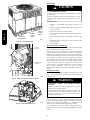
A09033
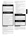
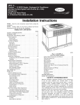
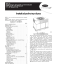
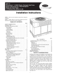
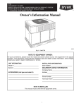
Fig. 1 -- Unit 48VR--A
(Low NOx Model Available)
Induced Draft (Combustion Air) Blower . . . . . . . . . . . . . .
Flue Gas Passageways . . . . . . . . . . . . . . . . . . . . . . . . . . . .
Limit Switch . . . . . . . . . . . . . . . . . . . . . . . . . . . . . . . . . . .
Burner Ignition . . . . . . . . . . . . . . . . . . . . . . . . . . . . . . . . .
Main Burners . . . . . . . . . . . . . . . . . . . . . . . . . . . . . . . . . . .
Removal of Gas Train . . . . . . . . . . . . . . . . . . . . . . . . . . . .
Outdoor Coil, Indoor Coil, & Condensate Drain Pan . . . .
Outdoor Fan . . . . . . . . . . . . . . . . . . . . . . . . . . . . . . . . . . .
Electrical Controls and Wiring . . . . . . . . . . . . . . . . . . . . .
Refrigerant Circuit . . . . . . . . . . . . . . . . . . . . . . . . . . . . . . .
Gas Input . . . . . . . . . . . . . . . . . . . . . . . . . . . . . . . . . . . . . .
Evaporator Airflow . . . . . . . . . . . . . . . . . . . . . . . . . . . . . .
Puron Items . . . . . . . . . . . . . . . . . . . . . . . . . . . . . . . . . . . .
TROUBLESHOOTING . . . . . . . . . . . . . . . . . . . . . . . . . . . . . .
START--UP CHECKLIST . . . . . . . . . . . . . . . . . . . . . . . . . . . .
47
47
47
47
47
47
47
48
48
48
49
49
49
50
50
SAFETY CONSIDERATIONS
Improper installation, adjustment, alteration, service maintenance,
or use can cause explosion, fire, electrical shock, or other
conditions which may cause death, personal injury, or property
damage. Consult a qualified installer, service agency, or your
distributor or branch for information or assistance. The qualified
installer or agency must use factory--authorized kits or accessories
when modifying this product. Refer to the individual instructions
packaged with the kits or accessories when installing.
Follow all safety codes. Wear safety glasses, protective clothing,
and work gloves. Have a fire extinguisher available. Read these
instructions thoroughly and follow all warnings or cautions
included in literature and attached to the unit. consult local
building codes, the current editions of the National Fuel Gas Code
(NFGC) NFPA 54/ANSI Z223.1, and the National Electrical Code
(NEC) NFPA 70.
In Canada refer to the current editions of the National Standards of
Canada CAN/CSA--B149.1 and .2 Natural Gas and Propane
Installation codes, and Canadian Electrical Code CSA C22.1
.
Recognize safety information. This is the safety--alert symbol
When you see this symbol on the unit and in instructions or manuals, be alert to the potential for personal injury. Understand these
1
signal words: DANGER, WARNING, and CAUTION. These
words are used with the safety--alert symbol. DANGER identifies
the most serious hazards which will result in severe personal injury
or death. WARNING signifies hazards which could result in personal injury or death. CAUTION is used to identify unsafe practices which may result in minor personal injury or product and property damage. NOTE is used to highlight suggestions which will
result in enhanced installation, reliability, or operation.
WARNING
!
ELECTRICAL SHOCK HAZARD
Failure to follow this warning could result in personal
injury or death.
48VR-- A
Before installing or servicing system, always turn off main
power to system and install lockout tag. There may be
more than one disconnect switch. Turn off accessory heater
power switch if applicable.
WARNING
!
PERSONAL
HAZARD
INJURY
AND
ENVIRONMENTAL
Failure to relieve system pressure could result in personal
injury and/or death.
1. Relieve pressure and recover all refrigerant before
servicing existing equipment, and before final unit disposal.
Use all service ports and open all flow--control devices,
including solenoid valves.
2. Federal regulations require that you do not vent
refrigerant into the atmosphere. Recover during system
repair or final unit disposal.
!
WARNING
FIRE, EXPLOSION, ELECTRICAL SHOCK AND
CARBON MONOXIDE POISONING HAZARD
Failure to follow this warning could result in personal
injury or unit damage.
A qualified installer or agency must use only
factory--authorized kits or accessories when modifying this
product.
!
CAUTION
CUT HAZARD
Failure to follow this caution may result in personal injury.
When removing access panels (see Fig. 17) or performing
maintenance functions inside your unit, be aware of sharp
sheet metal parts and screws. Although special care is taken
to reduce sharp edges to a minimum, be extremely careful
and wear appropriate protective clothing, safety glasses and
gloves when handling parts or reaching into the unit.
INTRODUCTION
The 48VR--A unit (see Fig. 1) is a fully self--contained,
combination Category I gas heating/electric heating and cooling
unit designed for outdoor installation (See Fig. 3 and 4 for unit
dimensions). All unit sizes have return and discharge openings for
both horizontal and downflow configurations, and are factory
shipped with all downflow duct openings covered. Units may be
installed either on a rooftop or on a cement slab. (See Fig. 5 for
roof curb dimensions).
In gas heating mode, this unit is designed for a minimum
continuous return--air temperature of 55_F (13_C) db and a
maximum continuous return--air temperature of 80_F (27_C) db.
Failure to follow these return--air temperature limits may affect
reliability of heat exchangers, motors, and other components.
Models with an N in the fifth position of the model number are
dedicated Low NOx units designed for California installations.
These models meet the California maximum oxides of nitrogen
(NOx) emissions requirements of 40 nanograms/joule or less as
shipped from the factory and must be installed in California Air
Quality Management Districts or any other regions in North
America where a Low NOx rule exists.
NOTE: Low NOx requirements apply only to natural gas
installations.
RECEIVING AND INSTALLATION
Step 1 — Check Equipment
Identify Unit
The unit model number and serial number are stamped on the unit
information plate. Check this information against shipping papers.
Inspect Shipment
Inspect for shipping damage before removing packaging materials.
If unit appears to be damaged or is torn loose from its anchorage,
have it examined by transportation inspectors before removal.
Forward claim papers directly to transportation company.
Manufacturer is not responsible for any damage incurred in transit.
Check all items against shipping list. Immediately notify the
nearest equipment distribution office if any item is missing. To
prevent loss or damage, leave all parts in original packages until
installation.
If the unit is to be mounted on a curb in a downflow application,
review Step 9 to determine which method is to be used to remove
the downflow panels before rigging and lifting into place. The
panel removal process may require the unit to be on the ground.
Step 2 — Provide Unit Support
For hurricane tie downs, contact distributor for details and PE
(Professional Engineering) Certificate if required.
Roof Curb
Install accessory roof curb in accordance with instructions shipped
with curb (See Fig. 5). Install insulation, cant strips, roofing, and
flashing. Ductwork must be attached to curb.
IMPORTANT: The gasketing of the unit to the roof curb is
critical for a water tight seal. Install gasketing material supplied
with the roof curb. Improperly applied gasketing also can result in
air leaks and poor unit performance.
Curb should be level to within 1/4 in. (6 mm). This is necessary
for unit drain to function properly. Refer to accessory roof curb
installation instructions for additional information as required.
Installation on older “G” series roof curbs.
Two accessory kits are available to aid in installing a new “G”
series unit on an old “G” roof curb.
1. Accessory kit number CPADCURB001A00, (small chassis)
and accessory kit number CPADCURB002A00, (large
chassis) includes roof curb adapter and gaskets for the
perimeter seal and duct openings. No additional
modifications to the curb are required when using this kit.
2. An alternative to the adapter curb is to modify the existing
curb by removing the outer horizontal flange and use
accessory kit number CPGSKTKIT001A00 which includes
spacer blocks (for easy alignment to existing curb) and
gaskets for the perimeter seal and duct openings. This kit is
used when existing curb is modified by removing outer
horizontal flange.
2
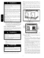
Do not place the unit where water, ice, or snow from an overhang
or roof will damage or flood the unit. Do not install the unit on
carpeting or other combustible materials. Slab--mounted units
should be at least 2 in. (51 mm) above the highest expected water
and runoff levels. Do not use unit if it has been under water.
WARNING
UNITS/STRUCTURAL DAMAGE HAZARD
Failure to follow this caution may result in property
damage.
Ensure there is sufficient clearance for saw blade when
cutting the outer horizontal flange of the roof curb so there
is no damage to the roof or flashing.
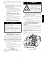
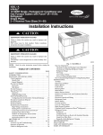
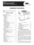
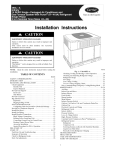
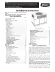
Slab Mount
Place the unit on a solid, level pad that is at least 2 in. (51 mm)
above grade. The pad should extend approximately 2 in. (51 mm)
beyond the casing on all 4 sides of the unit. (See Fig. 2.) Do not
secure the unit to the pad except when required by local codes.
OPTIONAL
RETURN
AIR
OPENING
OPTIONAL
SUPPLY
AIR
OPENING
Step 5 — Rig and Place Unit
Rigging and handling of this equipment can be hazardous for
many reasons due to the installation location (roofs, elevated
structures, etc.).
Only trained, qualified crane operators and ground support staff
should handle and install this equipment.
When working with this equipment, observe precautions in the
literature, on tags, stickers, and labels attached to the equipment,
and any other safety precautions that might apply.
Training for operators of the lifting equipment should include, but
not be limited to, the following:
1. Application of the lifter to the load, and adjustment of the
lifts to adapt to various sizes or kinds of loads.
2. Instruction in any special operation or precaution.
3. Condition of the load as it relates to operation of the lifting
kit, such as balance, temperature, etc.
Follow all applicable safety codes. Wear safety shoes and work
gloves.
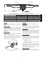
Inspection
2˝
(50.8mm)
EVAP. COIL
COND. COIL
A07926
Fig. 2 -- Slab Mounting Details
Step 3 — Field Fabricate Ductwork
Prior to initial use, and at monthly intervals, all rigging shackles,
clevis pins, and straps should be visually inspected for any
damage, evidence of wear, structural deformation, or cracks.
Particular attention should be paid to excessive wear at hoist
hooking points and load support areas. Materials showing any kind
of wear in these areas must not be used and should be discarded.
Secure all ducts to roof curb and building structure on vertical
discharge units. Do not connect ductwork to unit. For horizontal
applications, unit is provided with flanges on the horizontal
openings. All ductwork should be secured to the flanges. Insulate
and weatherproof all external ductwork, joints, and roof openings
with counter flashing and mastic in accordance with applicable
codes.
Ducts passing through an unconditioned space must be insulated
and covered with a vapor barrier.
If a plenum return is used on a vertical unit, the return should be
ducted through the roof deck to comply with applicable fire codes.
Read unit rating plate for any required clearances around ductwork.
Cabinet return--air static shall not exceed --.25 IN. W.C.
!
UNIT FALLING HAZARD
Failure to follow this warning could result in personal
injury or death.
Never stand beneath rigged units or lift over people.
!
WARNING
PROPERTY DAMAGE HAZARD
Step 4 — Provide Clearances
IMPORTANT: The unit must be secured to the curb by installing
screws through the bottom of the curb flange and into the unit base
rails. When installing large base units onto the common curb, the
screws must be installed before allowing the full weight of the unit
to rest on the curb. A minimum of six screws are required for large
base units. Failure to secure unit properly could result in an
unstable unit. See Warning near Rigging/Lifting information and
accessory curb instructions for more details.
The required minimum operating and service clearances are shown
in Fig. 3 and 4. Adequate combustion, ventilation and condenser
air must be provided.
IMPORTANT: Do not restrict outdoor airflow. An air restriction
at either the outdoor--air inlet or the fan discharge may be
detrimental to compressor life.
The outdoor fan pulls air through the outdoor coil and discharges
it through the top grille. Be sure that the fan discharge does not
recirculate to the outdoor coil. Do not locate the unit in either a
corner or under an overhead obstruction. The minimum clearance
under a partial overhang (such as a normal house overhang) is
48--in. (1219 mm) above the unit top. The maximum horizontal
extension of a partial overhang must not exceed 48--in. (1219 mm).
WARNING
Failure to follow this warning could result in personal
injury/death or property damage.
When straps are taut, the clevis should be a minimum of 36
in. (914 mm) above the unit top cover.
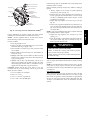
Rigging/Lifting of Unit (See Fig. 6)
!
WARNING
UNIT FALLING HAZARD
Failure to follow this warning could result in personal
injury or death.
Large base units must be secured to common curb before
allowing full weight of unit to rest on curb. Install screws
through curb into unit base rails while rigging crane is still
supporting unit.
Lifting holes are provided in base rails as shown in Fig. 3 and 4.
1. Leave top shipping skid on the unit for use as a spreader bar
to prevent the rigging straps from damaging the unit. If the
skid is not available, use a spreader bar of sufficient length
to protect the unit from damage.
3
48VR-- A
!
48VR-- A
2. Attach shackles, clevis pins, and straps to the base rails of
the unit. Be sure materials are rated to hold the weight of the
unit (See Fig. 6).
3. Attach a clevis of sufficient strength in the middle of the
straps. Adjust the clevis location to ensure unit is lifted level
with the ground.
After the unit is placed on the roof curb or mounting pad, remove
the top skid.
4
48VR-- A
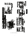
A13167
Fig. 3 -- 48VR--A24--30 Unit Dimensions
5
48VR-- A
A13168
Fig. 4 -- 48VR--A36--60 Unit Dimensions
6
Dashed lines show cross support
location for large basepan units.
B
G
HVAC unit
basepan
HVAC unit
base rails
C
Sealing
Gasket
Roofcurb
A
Anchor screw
H
F
Wood nailer*
Flashing field
supplied
Roofcurb*
Insulation
(field supplied)
Roofing material
field supplied
E
D
Cant strip
field supplied
SMALL/COMMON CURB
48VR-- A
A09413
*Provided with roofcurb
A09090
ROOF CURB DETAIL
B
C
G
SUPPLY
AIR
SMALL
BASE
UNIT
RETURN
AIR
LARGE
BASE
UNIT
H
F A
E
D
UNIT PLACEMENT ON
COMMON CURB
SMALL OR LARGE BASE UNIT
A09415
LARGE CURB
A09094
A09414
UNIT
SIZE
CATALOG
NUMBER
Small
or
Large
CPRFCURB010A00
Large
CPRFCURB011A00
CPRFCURB012A00
CPRFCURB013A00
A
IN.
(mm)
11
(279)
14
(356)
11
(279)
14
(356)
B (small / common
base)
IN. (mm)*
B (large
base)
IN. (mm)*
C
IN.
(mm)
D
IN.
(mm)
E
IN.
(mm)
F
IN.
(mm)
32.4
(822)
10 (254)
14 (356)
16
(406)
47.8
(1214)
H
IN. (mm)
30.6 (778)
2.7 (69)
43.9
(1116)
14 (356)
G
IN. (mm)
46.1 (1170)
42.2 (1072)
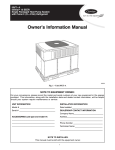
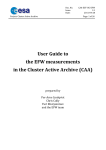
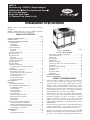
* Part Numbers CPRCURB010A00 and CPRCURB011A00 can be used on both small and large basepan units. The cross supports must be located based on
whether the unit is a small basepan or a large basepan.
NOTES:
1. Roof curb must be set up for unit being installed.
2. Seal strip must be applied, as required, to unit being installed.
3. Roof curb is made of 16--gauge steel.
4. Attach ductwork to curb (flanges of duct rest on curb).
5. Insulated panels: 1--in. (25.4 mm) thick fiberglass 1 lb. density.
Fig. 5 -- Roof Curb Dimensions
7
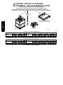
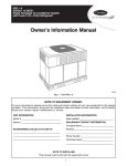
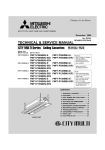
CAUTION - NOTICE TO RIGGERS
PRUDENCE - AVIS AUX MANIPULATEUR
ACCESS PANELS MUST BE IN PLACE WHEN RIGGING.
PANNEAUX D'ACCES DOIT ÊTRE EN PLACE POUR MANIPULATION.
Use top skid as spreader bar. / Utiliser la palette du haut comme barre de répartition
DUCTS
MINIMUM HEIGHT: 36" (914.4 mm)
HAUTEUR MINIMUM
SEAL STRIP MUST BE IN
PLACE BEFORE PLACING
UNIT ON ROOF CURB
48VR-- A
UNIT HEIGHT
HAUTEUR D'UNITÉ
BANDE SCELLANT DOIT ÊTRE
EN PLACE AVANT DE PLACER
L'UNITÉ SUR LA BASE DE TOIT
DETAIL A
VOIR DÉTAIL A
SEE DETAIL A
VOIR DÉTAIL A
50CY502286 2.0
A09051
Standard Copper Tube Aluminum Fin
SMALL CABINET
24
lb
kg
Rigging Weight
371
168
Unit
30
lb
379
kg
172
36
Unit *
lb
467
Rigging Weight
kg
212
LARGE CABINET
42
lb
kg
506
230
48
lb
509
60
kg
231
lb
562
kg
266
lb
667
kg
255
NOTE: See dimensional drawing for corner weights.
Optional Copper Tube Copper Fin
SMALL CABINET
24
Unit
lb
kg
Rigging Weight
429
195
30
lb
441
kg
200
NOTE: See dimensional drawing for corner weights.
36
Unit *
lb
529
Rigging Weight
kg
240
LARGE CABINET
42
lb
kg
590
268
Fig. 6 -- 48VR--A Unit Suggested Rigging
8
48
lb
587
60
kg
303
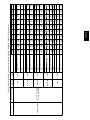
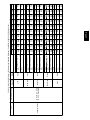
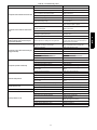
Table 1 – Physical Data -- Unit 48VR--A
COMPRESSORS
Quantity
REFRIGERANT (R --- 410A)
Quantity lb.
Quantity (kg)
REFRIGERANT METERING DEVICE
ORIFICE OD in.
(mm)
OUTDOOR COIL
Rows...Fins/in.
Face Area (sq ft)
OUTDOOR FAN
Nominal CFM
Diameter in.
Diameter (mm)
Motor Hp (Rpm)
INDOOR COIL
Rows...Fins/in.
Face Area (sq ft)
INDOOR BLOWER
Nominal Low Stage Cooling Airflow (Cfm)
Nominal High Stage Cooling Airflow (Cfm)
Size in.
Size (mm.)
Motor HP (RPM)
FURNACE SECTION*
Burner Orifice No. (Qty...Drill Size)
Natural Gas (Factory Installed)
Propane Gas
HIGH--PRESSURE SWITCH
(psig) Cut--out Reset (Auto)
LOSS--OF--CHARGE / LOW--PRESSURE
SWITCH (Liquid Line) (psig) cut--out Reset (auto)
RETURN--- AIR FILTERS†}
Throwaway Size in.
(mm)
24040
2
371
168
24060
2
371
168
30040
2 ---1/2
379
172
30060
2 ---1/2
379
172
36060
3
467
212
36090
3
467
212
42060
3 ---1/2
506
230
42090
3 ---1/2
506
230
11.0
5.0
14.6
6.6
14.6
6.6
.042 (2)
1.07 (2)
.042 (2)
1.07 (2)
.042 (2)
1.07 (2)
Scroll
1
9.0
4.1
9.0
4.1
10.0
4.5
10.0
11.0
4.5
5.0
TXV, Indoor TXV
.040 (2)
.042 (2)
1.02 (2)
1.07 (2)
.032 (2)
.81 (2)
.032 (2)
.81 (2)
.040 (2)
1.02 (2)
2..21
13.6
2...21
13.6
2...21
15.3
2...21
15.3
2...21
13.6
2...21
13.6
2...21
19.4
2...21
19.4
2100
24
609.6
1/12 (800)
2100
24
609.6
1/12 (800)
2500
24
609.6
1/8 (810)
2500
24
609.6
1/8 (810)
3000
26
660.4
1/5 (810)
3000
26
660.4
1/5 (810)
3000
26
660.4
1/5 (810
3000
26
660.4
1/5 (810)
3...17
3.7
3...17
3.7
3...17
3.7
3...17
3.7
3...17
4.7
3...17
4.7
3...17
4.7
3...17
4.7
650
850
10x10
254x254
1/2 (1050)
650
850
10x10
254x254
1/2 (1050)
750
1000
10x10
254x254
1/2 (1050)
750
1000
10x10
254x254
1/2 (1050)
900
1200
11x10
279.4x254
3/4 (1000)
900
1200
11x10
279.4x254
3/4 (1000)
1050
1400
11x10
279.4x254
3/4 (1075)
1050
1400
11x10
279.4x254
3/4 (1075)
2...44
2...55
3...44
3...55
2...44
2...55
3...44
3...55
3...44
3...55
3…38
3…53
3...44
3...55
3...38
3...53
650 +/-- 15
420 +/-- 25
20 +/-- 5
45 +/-- 5
20x20x1
508x508x25
20x24x1
508x610x25
24x30x1
610x762x25
*Based on altitude of 0 to 2000 ft (0 ---610 m).
{ Required filter sizes shown are based on the larger of the AHRI (Air Conditioning Heating and Refrigeration Institute) rated cooling airflow or the heating airflow velocity of 300 ft/minute for throwaway type. Air filter pressure drop for non ---standard filters must not exceed 0.08 IN. W.C.
} If using accessory filter rack refer to the filter rack installation instructions for correct filter sizes and quantity.
9
48VR-- A
UNIT SIZE
NOMINAL CAPACITY (ton)
SHIPPING WEIGHT** lb.
SHIPPING WEIGHT** (kg)
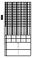
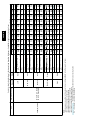
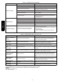
Table 1—Physical Data Con’t -- Unit 48VR--A
48VR-- A
UNIT SIZE
NOMINAL CAPACITY (ton)
SHIPPING WEIGHT lb
SHIPPING WEIGHT kg
COMPRESSORS
Quantity
REFRIGERANT (R --- 410A)
Quantity lb
Quantity (kg.)
REFRIGERANT METERING DEVICE
ORIFICE ID in.
(mm)
OUTDOOR COIL
Rows...Fins/in.
Face Area (sq ft)
OUTDOOR FAN
Nominal Cfm
Diameter in.
Diameter (mm)
Motor Hp (Rpm)
INDOOR COIL
Rows...Fins/in.
Face Area (sq ft)
INDOOR BLOWER
Nominal Low Stage Cooling Airflow (Cfm)
Nominal High Stage Cooling Airflow (Cfm)
Size in.
Size (mm)
Motor HP (RPM)
FURNACE SECTION*
Burner Orifice No. (Qty...Drill Size)
Natural Gas (Factory Installed)
Propane Gas
48090
4
509
231
48115
4
509
231
48130
4
509
231
60090
5
562
255
60115
5
562
255
60130
5
562
255
14.8
6.7
14.8
6.7
.052 (2)
1.32 (2)
.052 (2)
1.32 (2)
Scroll
1
12.0
5.4
12.0
5.4
12.0
14.8
5.4
6.7
TXV, Indoor TXV
.042 (2)
.052 (2)
1.07 (2)
1.32 (2)
,042 (2)
1.07 (2)
.042 (2)
1.07 (2)
2...21
17.5
2...21
17.5
2...21
17.5
2...21
23.3
2...21
23.3
2...21
23.3
3300
26
660.4
1/5 (810)
3300
26
660.4
1/5 (810)
3300
26
660.4
1/5 (810)
3600
26
660.4
1/5 (810)
3600
26
660.4
1/5 (810)
3600
26
660.4
1/5 (810)
3...17
5.7
3...17
5.7
3...17
5.7
4...17
5.7
4...17
5.7
4...17
5.7
1200
1600
11x10
279.4x254
1.0 (1075)
1200
1600
11x10
279.4x254
1.0 (1075)
1200
1600
11x10
279.4x254
1.0 (1075)
1400
1750
11x10
279.4x254
1.0 (1075)
1400
1750
11x10
279.4x254
1.0 (1075)
1400
1750
11x10
279.4x254
1.0 (1075)
3...38
3...53
3...33
3...51
3...31
3...49
3...38
3...53
3...33
3...51
3...31
3...49
HIGH--PRESSURE SWITCH
650 +/-- 15
(psig) Cut--out Reset (Auto)
420 +/-- 25
LOSS--OF--CHARGE / LOW--PRESSURE
20 +/--5
SWITCH (psig) cut--out Reset (auto)
45 +/-- 5
RETURN--AIR FILTERS Throwaway†} in.
24x36x1
(mm)
610x914x25
*Based on altitude of 0 to 2000 ft (0 ---610 m).
{ Required filter sizes shown are based on the larger of the AHRI (Air Conditioning Heating and Refrigeration Institute) rated cooling airflow or the heating airflow velocity of 300 ft/minute for throwaway type. Air filter pressure drop for non ---standard filters must not exceed 0.08 IN. W.C.
} If using accessory filter rack refer to the filter rack installation instructions for correct filter sizes and quantity.
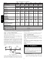
Step 6 — Connect Condensate Drain
NOTE: When installing condensate drain connection be sure to
comply with local codes and restrictions.
Model 48VR--A disposes of condensate water through a 3/4 in.
NPT fitting which exits through the base on the evaporator coil
access side. See Fig. 3 & 4 for location.
Condensate water can be drained directly onto the roof in rooftop
installations (where permitted) or onto a gravel apron in ground
level installations. Install a field--supplied 2--in. (51 mm)
condensate trap at the end of condensate connection to ensure
proper drainage. Make sure that the outlet of the trap is at least 1 in.
(25 mm) lower than the drain--pan condensate connection to
prevent the pan from overflowing (See Fig. 7). Prime the trap with
water. When using a gravel apron, make sure it slopes away from
the unit.
downward at a slope of at least 1--in. (25 mm) for every 10 ft (3.1
m) of horizontal run. Be sure to check the drain tube for leaks.
Step 7 — Install Flue Hood
The flue assembly is secured and shipped in the return air duct.
Remove duct cover to locate the assembly (See Fig. 9).
NOTE:
Dedicated low NOx models MUST be installed in
California Air Quality Management Districts where a Low NOx
rule exists.
These models meet the California maximum oxides of nitrogen
(NOx) emissions requirements of 40 nanograms/joule or less as
shipped from the factory.
NOTE: Low NOx requirements apply only to natural gas
installations.
!
TRAP
OUTLET
WARNING
CARBON MONOXIDE POISONING HAZARD
Failure to follow this warning could result in personal
injury or death.
1-in. (25 mm) min.
The venting system is designed to ensure proper venting.
The flue hood assembly must be installed as indicted in this
section of the unit installation instructions.
2-in. (51 mm) min.
A09052
Fig. 7 -- Condensate Trap
Connect a drain tube using a minimum of 3/4--in. PVC or 3/4--in.
copper pipe (all field--supplied) at the outlet end of the 2--in. (51
mm) trap. Do not undersize the tube. Pitch the drain tube
Install the flue hood as follows:
1. This installation must conform with local building codes
and with NFPA 54/ANSI Z223.1 National Fuel Gas Code
(NFGC), (in Canada, CAN/CGA B149.1, and B149.2)
10
2. Protect all segments of piping system against physical and
thermal damage. Support all piping with appropriate straps,
hangers, etc. Use a minimum of one hanger every 6 ft (1.8
m). For pipe sizes larger than 1/2 in., follow
recommendations of national codes.
3. Apply joint compound (pipe dope) sparingly and only to
male threads of joint when making pipe connections. Use
only pipe dope that is resistant to action of liquefied
petroleum gases as specified by local and/or national codes.
Never use Teflon tape.
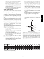
4. Install sediment trap in riser leading to heating section (See
Fig. 8). This drip leg functions as a trap for dirt and
condensate.
5. Install an accessible, external, manual main shutoff valve in
gas supply pipe within 6 ft (1.8 m) of heating section.
6. Install ground--joint union close to heating section between
unit manual shutoff and external manual main shut--off
valve.
7. Pressure test all gas piping in accordance with local and
national plumbing and gas codes before connecting piping
to unit.
Step 8 — Install Gas Piping
The gas supply pipe enters the unit through the access hole
provided. The gas connection to the unit is made to the 1/2--in.
(12.7 mm) FPT gas inlet on the gas valve.
Install a gas supply line that runs to the heating section. Refer to
the NFGC for gas pipe sizing. Do not use cast--iron pipe. It is
recommended that a black iron pipe is used. Check the local utility
for recommendations concerning existing lines. Size gas supply
piping for 0.5 IN. W.C. maximum pressure drop. Never use pipe
smaller than the 1/2--in. (12.7 mm) FPT gas inlet on the unit gas
valve.
For natural gas applications, the gas pressure at unit gas connection
must not be less than 4.0 IN. W.C. or greater than 13 IN. W.C.
while the unit is operating. For propane applications, the gas
pressure must not be less than 11.0 IN. W.C. or greater than 13 IN.
W.C. at the unit connection.
A 1/8--in. (3.2 mm) NPT plugged tapping, accessible for test gauge
connection, must be installed immediately upstream of the gas
supply connection to the gas valve.
When installing the gas supply line, observe local codes pertaining
to gas pipe installations. Refer to the NFPA 54/ANSI Z223.1 latest
edition (in Canada, CAN/CGA B149.1).
NOTE: In the state of Massachusetts:
1. Gas supply connections MUST be performed by a licensed
plumber or gas fitter.
2. When flexible connectors are used, the maximum length
shall not exceed 36 inches (915 mm).
3. When lever handle type manual equipment shutoff valves
are used, they shall be T--handle valves.
4. The use of copper tubing for gas piping is NOT approved
by the state of Massachusetts.
In the absence of local building codes, adhere to the following
pertinent recommendations:
1. Avoid low spots in long runs of pipe. Grade all pipe 1/4 in.
(6.35 mm) for every 15 ft (4.6 m) of length to prevent traps.
Grade all horizontal runs downward to risers. Use risers to
connect to heating section and to meter.
IN
OUT
TEE
NIPPLE
CAP
C99020
Fig. 8 -- Sediment Trap
NOTE: Pressure test the gas supply system after the gas supply
piping is connected to the gas valve. The supply piping must be
disconnected from the gas valve during the testing of the piping
systems when test pressure is in excess of 0.5 psig. Pressure test the
gas supply piping system at pressures equal to or less than 0.5 psig.
The unit heating section must be isolated from the gas piping
system by closing the external main manual shutoff valve and
slightly opening the ground--joint union.
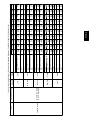
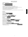
Table 2 – Maximum Gas Flow Capacity*
LENGTH OF PIPE FT (m)†
10
20
30
40
50
60
70
80
90
100
125
150
175
200
(3)
(6)
(9)
(12)
(15)
(18)
(21)
(24)
(27)
(30)
(38)
(46)
(53)
(61)
1/2
.622
175
120
97
82
73
66
61
57
53
50
44
40
—
—
3/4
.824
360
250
200
170
151
138
125
118
110
103
93
84
77
72
1
1.049
680
465
375
320
285
260
240
220
205
195
175
160
145
135
1--- 1/4
1.380
1400
950
770
600
580
530
490
460
430
400
360
325
300
280
1--- 1/2
1.610
2100
1460
1180
990
900
810
750
690
650
620
550
500
460
430
*Capacity of pipe in cu ft of gas per hr for gas pressure of 0.5 psig or less. Pressure drop of 0.5 ---IN. W.C. (based on a 0.60 specific gravity gas). Refer to Table 2
and National Fuel Gas Code NFPA 54/ANSI Z223.1.
{ This length includes an ordinary number of fittings.
NOMINAL
IRON PIPE
SIZE (IN.)
INTERNAL
DIAMETER
(IN.)
11
48VR-- A
latest revision. Refer to Provincial and local plumbing or
wastewater codes and other applicable local codes.
2. Remove flue hood from shipping location (inside the return
section of the blower compartment--see Fig. 9). Remove the
return duct cover to locate the flue hood. Place flue hood
assembly over flue panel. Orient screw holes in flue hood
with holes in the flue panel.
3. Secure flue hood to flue panel by inserting a single screw on
the top flange and the bottom flange of the hood.
!
WARNING
FIRE OR EXPLOSION HAZARD
Failure to follow this warning could result in personal injury,
death and/or property damage.
--Connect gas pipe to unit using a backup wrench to avoid
damaging gas controls.
NOTE: These panels are held in place with tabs similar to an
electrical knockout. Reinstall horizontal duct covers (see Fig. 9)
shipped on unit from factory. Insure openings are air and
watertight.
NOTE: The design and installation of the duct system must be in
accordance with the standards of the NFPA for installation of
nonresidence--type air conditioning and ventilating systems, NFPA
90A or residence--type, NFPA 90B; and/or local codes and
ordinances.
--Never purge a gas line into a combustion chamber. Never
test for gas leaks with an open flame. Use a commercially
available soap solution made specifically for the detection of
leaks to check all connections. A fire or explosion may result
causing property damage, personal injury or loss of life.
48VR-- A
--Use proper length of pipe to avoid stress on gas control
manifold.
--If a flexible connector is required or allowed by authority
having jurisdiction, black iron pipe shall be installed at
furnace gas valve and extend a minimum of 2 in. (51 mm)
outside furnace casing.
--If codes allow a flexible connector, always use a new
connector. Do not use a connector which has previously
serviced another gas appliance.
Horizontal Duct Covers
8. Check for gas leaks at the field--installed and
factory--installed gas lines after all piping connections have
been completed. Use a commercially available soap solution
(or method specified by local codes and/or regulations).
A09076
Basepan
Downflow
(Vertical)
Supply
Knockout
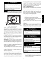
Step 9 — Install Duct Connections
The unit has duct flanges on the supply-- and return--air openings
on the side and bottom of the unit. For downshot applications, the
ductwork connects to the roof curb (See Fig. 3 and 4 for
connection sizes and locations).
Basepan
Downflow
(Vertical)
Return
Knockout
Configuring Units for Downflow (Vertical) Discharge
!
WARNING
ELECTRICAL SHOCK HAZARD
Failure to follow this warning could result in personal
injury or death.
Before installing or servicing system, always turn off main
power to system and install lockout tag. There may be
more than one disconnect switch.
1. Open all electrical disconnects before starting any service
work.
2. Remove horizontal (metal) duct covers to access vertical
(downflow) discharge duct knockouts in unit basepan. (See
Fig. 9.)
!
CAUTION
PROPERTY DAMAGE HAZARD
Failure to follow this caution may result in property damage.
Collect ALL screws that were removed. Do not leave screws
on rooftop as permanent damage to the roof may occur.
To remove downflow return and supply knockout covers, break
front and right side connecting tabs with a screwdriver and
hammer. Push cover down to break rear and left side tabs.
A09077
Fig. 9 -- Supply and Return Duct Opening
Adhere to the following criteria when selecting, sizing, and
installing the duct system:
1. Units are shipped for horizontal duct installation (by
removing duct covers).
2. Select and size ductwork, supply--air registers, and
return--air grilles according to American Society of Heating,
Refrigeration and Air Conditioning Engineers (ASHRAE)
recommendations.
3. Use flexible transition between rigid ductwork and unit to
prevent transmission of vibration. The transition may be
screwed or bolted to duct flanges. Use suitable gaskets to
ensure weather--tight and airtight seal.
4. All units must have field--supplied filters or accessory filter
rack installed in the return--air side of the unit.
Recommended sizes for filters are shown in Table 1.
5. Size all ductwork for maximum required airflow (either
heating or cooling) for unit being installed. Avoid abrupt
duct size increases or decreases or performance may be
affected.
6. Adequately insulate and weatherproof all ductwork located
outdoors. Insulate ducts passing through unconditioned
space, and use vapor barrier in accordance with latest issue
of Sheet Metal and Air Conditioning Contractors National
Association (SMACNA) and Air Conditioning Contractors
of America (ACCA) minimum installation standards for
12
Step 10 — Install Electrical Connections
!
WARNING
ELECTRICAL SHOCK HAZARD
Failure to follow this warning could result in personal
injury or death.
The unit cabinet must have an uninterrupted, unbroken
electrical ground. This ground may consist of an electrical
wire connected to the unit ground screw in the control
compartment, or conduit approved for electrical ground
when installed in accordance with NFPA 70 (NEC) (latest
edition) (in Canada, Canadian Electrical Code CSA C22.1)
and local electrical codes.
!
CAUTION
UNIT COMPONENT DAMAGE HAZARD
See unit wiring label (Fig. 14, 16 and 17) and Fig. 10 for reference
when making high voltage connections. Proceed as follows to
complete the high--voltage connections to the unit.
Single phase units:
1. Run the high--voltage (L1, L2) and ground lead into the
control box.
2. Connect ground lead to chassis ground connection.
3. Locate the black and yellow wires connected to the line side
of the contactor (if equipped).
4. Connect field L1 to black wire from connection 11 of the
compressor contactor.
5. Connect field wire L2 to yellow wire from connection 23 of
the compressor contactor.
Three--phase units:
1. Run the high--voltage (L1, L2, L3) and ground lead into the
control box.
2. Connect ground lead to chassis ground connection.
3. Locate the black and yellow wires connected to the line side
of the contactor (if equipped).
4. Connect field L1 to black wire from connection 11 of the
compressor contactor.
5. Connect field wire L3 to yellow wire from connection 13 of
the compressor contactor.
6. Connect field wire L2 to blue wire from compressor.
Special Procedures for 208-- v Operation
Failure to follow this caution may result in damage to the
unit being installed.
1. Make all electrical connections in accordance with NFPA
70 (NEC) (latest edition) and local electrical codes
governing such wiring. In Canada, all electrical
connections must be in accordance with CSA standard
C22.1 Canadian Electrical Code Part 1 and applicable
local codes. Refer to unit wiring diagram.
2. Use only copper conductor for connections between
field--supplied electrical disconnect switch and unit. DO
NOT USE ALUMINUM WIRE.
3. Be sure that high--voltage power to unit is within
operating voltage range indicated on unit rating plate. On
3--phase units, ensure phases are balanced within 2
percent. Consult local power company for correction of
improper voltage and/or phase imbalance.
4. Insulate low--voltage wires for highest voltage contained
within conduit when low--voltage control wires are in
same conduit as high--voltage wires.
5. Do not damage internal components when drilling
through any panel to mount electrical hardware, conduit,
etc.
!
WARNING
ELECTRICAL SHOCK HAZARD
Failure to follow this warning could result in personal
injury or death.
Make sure the power supply to the unit is switched OFF and
install lockout tag. before making any wiring changes. With
disconnect switch open, move black wire from transformer
(3/16 in. [4.8 mm]) terminal marked 230 to terminal marked
208. This retaps transformer to primary voltage of 208 vac.
!
WARNING
ELECTRICAL SHOCK FIRE/EXPLOSION HAZARD
Failure to follow this warning could result in personal
injury or death and property damage.
Before making any wiring changes, make sure the gas
supply is switched off first. Then switch off the power
supply to the unit and install lockout tag.
High-- Voltage Connections
Control Voltage Connections
When routing power leads into unit, use only copper wire between
disconnect and unit. The high voltage leads should be in a conduit
until they enter the duct panel; conduit termination at the duct
panel must be watertight.
The unit must have a separate electrical service with a
field--supplied, waterproof disconnect switch mounted at, or within
sight from, the unit. Refer to the unit rating plate, NEC and local
codes for maximum fuse/circuit breaker size and minimum circuit
amps (ampacity) for wire sizing.
The field--supplied disconnect switch box may be mounted on the
unit over the high--voltage inlet hole when the standard power and
low--voltage entry points are used (See Fig. 3 and 4 for acceptable
location).
NOTE:
Field supplied disconnect switch box should be
positioned so that it does not cover up any of the unit gas
combustion supply air louvers.
Do not use any type of power--stealing thermostat. Unit control
problems may result.
Use no. 18 American Wire Gage (AWG) color--coded, insulated
(35_C minimum) wires to make the control voltage connections
between the thermostat and the unit. If the thermostat is located
more than 100 ft (30.5 m) from the unit (as measured along the
control voltage wires), use no. 16 AWG color--coded, insulated
(35_C minimum) wires.
13
48VR-- A
heating and air conditioning systems. Secure all ducts to
building structure.
7. Flash, weatherproof, and vibration isolate all openings in
building structure in accordance with local codes and good
building practices.
Standard Connection
Run the low--voltage leads from the thermostat, through the inlet
hole, and into unit low--voltage splice box.
Locate nine 18--gage wires leaving control box. These low--voltage
connection leads can be identified by the colors red, green, yellow,
brown, blue, white, pink, black and orange (See Fig. 10). Ensure
the leads are long enough to be routed into the low--voltage splice
box (located below right side of control box). Route leads through
hole in bottom of control box and make low--voltage connections
(See Fig. 10). Secure all cut wires, so that they do not interfere with
operation of unit.
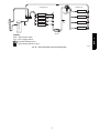
HIGH VOLTAGE
POWER LEADS
(SEE UNIT WIRING
LABEL)
POWER
SUPPLY
3-PHASE SHOWN
1-PHASE USES
TWO POWER
LEADS
EQUIP GR
FIELD-SUPPLIED
FUSED DISCONNECT
CONTROL BOX
48VR-- A
WHT(W1)
YEL (Y)
GRN(G)
RED(R)
LOW-VOLTAGE
POWER LEADS
(SEE UNIT
WIRING LABEL)
BRN(C)
BLU(DH)
PINK(Y2)
BLK(W2)
ORN(O)
W/W1
Y1/Y
G
R
THERMOSTAT
(TYPICAL)
C
DH
(DH ON 208/230 VAC
MODELS ONLY)
Transformer Protection
Y2
W2
“balance point”, the heat pump will not be allowed to operate (i.e.
locked out), and the gas furnace will be used to satisfy the indoor
temperature. There are three separate concepts which are related to
selecting the final “balance point” temperature. Read each of the
following carefully to determine the best “balance point” in a
hybrid installation:
1. Capacity Balance Temperature: This is a point where the
heat pump cannot provide sufficient capacity to keep up
with the indoor temperature demand because of declining
outdoor temperature. At or below this point, the furnace is
needed to maintain proper indoor temperature.
2. Economic Balance Temperature: Above this point, the heat
pump is the most cost efficient to operate, and below this
point the furnace is the most cost efficient to operate. This
can be somewhat complicated to determine and it involves
knowing the cost of gas and electricity, as well as the
efficiency of the furnace and heat pump. For the most
economical operation, the heat pump should operate above
this temperature (assuming it has sufficient capacity) and the
furnace should operate below this temperature.
3. Comfort Balance Temperature: When the heat pump is
operating below this point, the indoor supply air feels
uncomfortable (i.e. too cool). This is purely subjective and
will depend on the homeowner’s idea of comfort. Below
this temperature the gas furnace should operate in order to
satisfy the desire for indoor comfort.
(W2 ON 208/230 VAC
MODELS ONLY)
O
SPLICE BOX
A13152
Fig. 10 -- High-- and Control--Voltage Connections
The transformer is of the energy--limiting type, however a direct
short will likely blow a secondary fuse. If an overload or short is
present, correct overload condition and check for blown fuse on
Indoor Fan board or Integrated Gas Controller. Replace fuse as
required with correct size and rating.
PRE--START--UP
IMPORTANT: Dehumidification control must open control
circuit on humidity rise above set point.
Use of the dehumidification cooling fan speed requires use of
either a 24 VAC dehumidistat or a thermostat which includes
control of a 24 VAC dehumidistat connection. In either case, the
dehumidification control must open the control circuit on humidity
rise above the dehumidification set point.
!
WARNING
ENVIRONMENTAL,
FIRE,
ELECTRICAL SHOCK HAZARD
EXPLOSION,
Failure to follow this warning could result in personal
injury or death.
1. Follow recognized safety practices and wear protective
goggles when checking or servicing refrigerant system.
2. Do not operate compressor or provide any electric power
to unit unless compressor plug is in place and secured.
3. Do not remove compressor plug until all electrical
sources are disconnected and tagged.
4. Relieve and recover all refrigerant from system before
touching or disturbing compressor plug if refrigerant
leak is suspected around compressor terminals.
5. Never attempt to repair soldered connection while
refrigerant system is under pressure.
6. Do not use torch to remove any component. System
contains oil and refrigerant under pressure.
To remove a component, wear protective goggles and
proceed as follows:
a. Shut off electrical power to unit and install
lockout tag.
b. Relieve and reclaim all refrigerant from system
using both high-- and low--pressure ports.
c. Cut component connecting tubing with tubing
cutter and remove component from unit.
d. Carefully unsweat remaining tubing stubs when
necessary. Oil can ignite when exposed to torch
flame.
Heat Anticipator Setting (Electro-- Mechanical
Thermostats only)
The room thermostat heat anticipator must be properly adjusted to
ensure proper heating performance. Set the heat anticipator, using
an ammeter between the W1 and R terminals to determine the exact
required setting.
NOTE: For thermostat selection purposes, use 0.18 amp for the
approximate required setting. Failure to make a proper heat
anticipator adjustment will result in improper operation, discomfort
to the occupants of the conditioned space, and inefficient energy
utilization; however, the required setting may be changed slightly
to provide a greater degree of comfort for a particular installation.
Balance Point Setting-- Thermidistat or Hybrid
Thermostat
BALANCE POINT TEMPERATURE--The “balance point”
temperature is a setting which affects the operation of the heating
mode. This is a field--selected input temperature (range 5 to 55_F)
(--15 to 12_C) where the Thermidistat or dual fuel thermostat will
monitor outdoor air temperature and decide whether to enable or
disable the heat pump. If the outdoor temperature is above the
“balance point”, the heat pump will energize first to try to satisfy
the indoor temperature demand. If the heat pump does not make a
sufficient improvement within a reasonable time period (i.e. 15
minutes), then the gas furnace will come on to satisfy the indoor
temperature demand. If the outdoor temperature is below the
14
!
WARNING
FIRE, EXPLOSION HAZARD
Failure to follow this warning could result in personal
injury, death or property damage.
Do not purge gas supply into the combustion chamber. Do
not use a match or other open flame to check for gas leaks.
Use a commercially available soap solution made
specifically for the detection of leaks to check all
connections. A fire or explosion may result causing
property damage, personal injury or loss of life.
4. Verify the following conditions:
a. Make sure gas line is free of air. Before lighting the unit
for the first time, perform the following with the gas
valve in the OFF position:
NOTE: If the gas supply pipe was not purged before connecting
the unit, it will be full of air. It is recommended that the ground
joint union be loosened, and the supply line be allowed to purge
until the odor of gas is detected. Never purge gas lines into a
combustion chamber. Immediately upon detection of gas odor,
retighten the union. Allow 5 minutes to elapse, then light unit.
b. Make sure that outdoor--fan blade is correctly positioned
in the fan orifice.
c. Make sure that air filter(s) is in place.
d. Make sure that condensate drain trap is filled with water
to ensure proper drainage.
e. Make sure that all tools and miscellaneous loose parts
have been removed.
START--UP
!
WARNING
EXPLOSION HAZARD
Failure to follow this warning could
result in death, serious personal injury,
and/or property damage.
Never use air or gases containing
oxygen for leak testing or operating
refrigerant compressors. Pressurized
mixtures of air or gases containing
oxygen can lead to an explosion.
1. Locate leak and make sure that refrigerant system pressure
has been relieved and reclaimed from both high-- and
low--pressure ports.
2. Repair leak following accepted practices.
NOTE: Install a filter drier whenever the system has been opened
for repair.
3. Add a small charge of Puron (R--410A) refrigerant vapor to
system and leak--test unit.
4. Recover refrigerant from refrigerant system and evacuate to
500 microns if no additional leaks are found.
5. Charge unit with Puron (R--410A) refrigerant, using an
accurate scale. Refer to unit rating plate for required charge.
Step 2 — Start--up Gas Heating and Make
Adjustments
Complete the required procedures given in the Pre--Start--Up
section before starting the unit. Do not jumper any safety devices
when operating the unit. Make sure that burner orifices are
properly aligned. Unstable operation my occur when the burner
orifices in the manifold are misaligned.
Follow the lighting instructions on the heating section operation
label (located on the inside of the control access panel) to start the
heating section.
NOTE: Make sure that gas supply has been purged, and that all
gas piping has been checked for leaks.
Pipe Plug
Manifold
A07679
Step 1 — Check for Refrigerant Leaks
Fig. 11 -- Burner Assembly
Proceed as follows to locate and repair a refrigerant leak and to
charge the unit:
15
48VR-- A
Use the Start--Up Checklist supplied at the end of this book and
proceed as follows to inspect and prepare the unit for initial
start--up:
1. Remove access panels (see Fig. 20).
2. Read and follow instructions on all DANGER, WARNING,
CAUTION, and INFORMATION labels attached to, or
shipped with unit.
3. Make the following inspections:
a. Inspect for shipping and handling damage, such as
broken lines, loose parts, disconnected wires, etc.
b. Inspect for oil at all refrigerant tubing connections and
on unit base. Detecting oil generally indicates a
refrigerant leak.
c. Leak--test all refrigerant tubing connections using
electronic leak detector, or liquid--soap solution. If a
refrigerant leak is detected, see following Check for
Refrigerant Leaks section.
d. Inspect all field-- and factory--wiring connections. Be
sure that connections are completed and tight.
e. Ensure wires do not touch refrigerant tubing or sharp
sheet metal edges.
f. Inspect coil fins. If damaged during shipping and
handling, carefully straighten fins with a fin comb.
IN THE U.S.A.:
The input rating for altitudes above 2,000 ft (610 m) must be
reduced by 4% for each 1,000 ft (305 m) above see level.
For installations below 2,000 ft (610 m), refer to the unit rating
plate.
For installations above 2,000 ft (610 m). multiply the input on the
rating plate by the derate multiplier in Table 3 for correct input rate.
If the natural gs is not de--rated by the utility company refer to
Table 4 for correct orifice sizes and manifold pressures.
BURNER FLAME
BURNER
MANIFOLD
Table 3 – Altitude Derate Multiplier for U.S.A.*
C99021
Fig. 12 -- Monoport Burner
48VR-- A
Check Gas Heating Control
Start and check the unit for proper heating control operation as
follows (see furnace lighting instructions located on the inside of
the control access panel):
1. Place room thermostat SYSTEM switch in the GAS HEAT
position and the fan switch in AUTO position.
2. Set the heating temperature control setting several degrees
higher than the room temperature reading.
3. The induced--draft motor will always start on high speed for
the ignition sequence, regardless of the heating stage called.
4. After a pre--purge time of 15 sec with the induced--draft motor on high speed, the sparker will be energized for 3--to--8
sec, and the gas valve will be energized on low stage. If the
burners do not light, there is a 20--sec delay before another
ignition attempt. If the burners still do not light by the 4th
consecutive ignition attempt, there is a lockout. To reset the
lockout, break the 24--v power to W1 and W2.
5. Once flame is established the integrated gas unit controller
(IGC) will look for 24--v power to W1 and W2. If there is
24--v power to W1 only, the IGC will switch the induced-draft motor down to low speed and maintain low stage on
the gas valve. If there is 24--v power to both W1 and W2,
the IGC will maintain the induced--draft motor on high
speed and switch the gas valve to high stage.
6. With the desired temperature set several degrees higher than
the room temperature, most thermostats will energize low
and high stage. Verify that the gas valve is energized on
high stage and the induced--draft motor is on high speed.
7. Verify proper operation of low stage (induced--draft motor
on low speed and gas valve on high stage) by turning the
heating temperature control setting down until the desired
temperature is 1 degree above room temperature. Most thermostats will energize low stage only with a 1 degree differential.
8. The evaporator fan will turn on 30 sec after the flame has
been established. If there is 24--v power to W1 only, the fan
will run on low heat speed. If there is 24--v power to W1
and W2, the fan will run on high heat speed. Once the heating coll is satisfied, the IGC will turn the fan off after a
field--selectable fan delay of 90, 120, 150, or 180 sec is
completed.
Check Gas Input
Check gas input and manifold pressure after unit start--up (See
Table 5). If adjustment is required proceed as follows:
S The rated gas inputs shown in Table 5 is for altitudes from sea
level to 2000 ft (610 m) above sea level. These inputs are based
on natural gas with a heating value of 1025 Btu/ft3 at 0.60
specific gravity, or propane gas with a heating value of 2500
Btu/ft3 at 1.5 specific gravity.
ALTITUDE FT (M)
PERCENT OF DERATE
DERATE MULTIPLIER
FACTOR{
0--- 2000
(0--- 610)
0
1.00
2001--- 3000*
(610--- 914)
8--- 12
0.90
3001--- 4000
(915--- 1219)
12--- 16
0.86
4001--- 5000
(1220--- 1524)
16--- 20
0.82
5001--- 6000
(1524 --- 1829)
20--- 24
0.78
6001--- 7000
(1829--- 2134)
24--- 28
0.74
7001--- 8000
(2134--- 2438)
28--- 32
0.70
8001--- 9000
(2439--- 2743)
32--- 36
0.66
9001--- 10,000
(2744--- 3048)
36--- 40
0.62
*In Canada see Canadian Altitude Adjustment.
{Derate multiplier factors are based on midpoint altitude for altitude range.
IN CANADA:
The input rating for altitudes from 2,000 (610 m) to 4,500 ft (1372
m) above sea level must be derated 10% by an authorized Gas
Conversion Station or Dealer.
EXAMPLE:
90,000 Btu/hr Input Furnace Installed at 4300 ft.
Furnace Input Rate at
Sea Level
90,000
X Derate Multiplier
Factor
= Furnace Input Rate at
Installation Altitude
X
=
0.90
81,000
When the gas supply being used has a different heating value or
specific gravity, refer to national and local codes, or contact your
distributor to determine the required orifice size.
!
CAUTION
UNIT DAMAGE HAZARD
Failure to follow this caution may result in reduced unit
and/or component life.
Do Not redrill an orifice. Improper drilling (burrs,
out--of--round holes, etc.) can cause excessive burner noise
and misdirection of burner flame. If orifice hole appears
damaged or it is suspected to have been redrilled, check
orifice hole with a numbered drill bit of correct size.
Adjust Gas Input
The gas input to the unit is determined by measuring the gas flow
at the meter or by measuring the manifold pressure. Measuring the
gas flow at the meter is recommended for natural gas units. The
manifold pressure must be measured to determine the input of
propane gas units.
Measure Gas Flow (Natural Gas Units)
Minor adjustment to the gas flow can be made by changing the
manifold pressure(s). The manifold pressure(s) must be maintained
between 3.2 and 3.8 IN. W.C. for high stage and between 1.4 and
2.0 IN. W.C. for low stage (208/230 VAC models). For 460 VAC
models, manifold pressure must be maintained between 3.2 and 3.8
IN. W.C.
16
PLASTIC ADJUST SCREW
ON/OFF SWITCH
REGULATOR SPRING
1/2˝ NPT INLET
INLET
PRESSURE TAP
HIGH STAGE GAS
PRESSURE REGULATOR
ADJUSTMENT
LOW STAGE
GAS PRESSURE
REGULATOR ADJUSTMENT
MANIFOLD
PRESSURE TAP
1/2˝ NPT OUTLET
A04167
Fig. 13 -- Two--Stage Gas Valve (208/230 VAC Models)
If larger adjustments are required, change main burner orifices
following the recommendations of national and local codes.
NOTE: All other appliances that use the same meter must be
turned off when gas flow is measured at the meter.
Proceed as follows:
1. Turn off gas supply to unit.
2. Remove pipe plug on manifold (See Fig. 11) and connect
manometer. Turn on gas supply to unit.
3. Record number of seconds for gas meter test dial to make
one revolution.
4. Divide number of seconds in Step 3 into 3600 (number of
seconds in one hr).
5. Multiply result of Step 4 by the number of cubic feet (cu ft)
shown for one revolution of test dial to obtain cubic feet (cu
ft) of gas flow per hour.
6. Multiply result of Step 5 by Btu heating value of gas to
obtain total measured input in Btuh. Compare this value
with heating input shown in Table 5 (Consult the local gas
supplier if the heating value of gas is not known).
EXAMPLE: Assume that the size of test dial is 1 cu ft, one
revolution takes 32 sec and the heating value of the gas is 1050
Btu/ft3. Proceed as follows:
1. 32 sec to complete one revolution.
2. 3600 32 = 112.5.
3. 112.5 x 1 =112.5 ft3 of gas flow/hr.
4. 112.5 x 1050 = 118,125 Btuh input.
If the desired gas input is 115,000 Btuh, only a minor change in the
manifold pressure is required.
Observe manifold pressure(s) and proceed as follows to adjust gas
input(s):
1. Remove regulator cover screw(s) over plastic adjustment
screw(s) on gas valve (see Fig. 13).
2. Turn the high stage plastic adjustment screw clockwise to
increase gas input and counterclockwise to decrease input
(see Fig. 13). Manifold pressure must be between 3.2 and
3.8 IN. W.C. for high stage.
3. Replace high stage regulator cover screw on gas valve (see
Fig. 13).
4. Turn the low stage plastic adjustment screw clockwise to increase gas input and counterclockwise to decrease input (see
Fig. 13). Low stage manifold pressure must be between 1.4
and 2.0 IN. W.C.
NOTE: Low stage manifold pressure must be adjusted after high
stage manifold pressure is already adjusted.
5. Replace low stage regulator cover screw(s) on gas valve
(see Fig. 13).
6. Turn off gas supply to unit. Remove manometer from pressure tap and replace pipe plug on manifold (see Fig. 11).
Turn on gas and check for leaks
!
WARNING
FIRE AND UNIT DAMAGE HAZARD
Failure to follow this warning could result in personal
injury or death and/or property damage.
Unsafe operation of the unit may result if manifold pressure
is outside this range.
Measure Manifold Pressure (Propane Units)
Refer to propane kit installation instructions for properly checking
gas input.
NOTE: For installations below 2,000 ft (610 m), refer to the unit
rating plate for proper propane conversion kit. For installations
above 2,000 ft (610 m), contact your distributor for proper propane
conversion kit.
Check Burner Flame
With control access panel (see Fig. 20) removed, observe the unit
heating operation. Watch the burner flames to see if they are light
blue and soft in appearance, and that the flames are approximately
the same for each burner. Propane will have blue flame (See Fig.
12). Refer to the Maintenance section for information on burner
removal.
17
48VR-- A
REGULATOR COVER SCREW
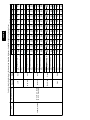
Table 4 – Natural Gas Orifice Sizes and Manifold Pressure
208/230VAC Models
ALTITUDE OF INSTALLATION (FT. [m] ABOVE SEA LEVEL) U.S.A.*
2001 to
0 to 2000
3001 to 4000
4001 to 5000
5001 to 6000
3000*
[0 to 610]
[915 to 1219]
[1220 to 1524]
[1524 to 1829]
[610 to 914]
44 (2)
45 (2)†
48 (2)†
48 (2)†
48 (2)†
Nameplate
Input,
High Stage
(Btu/hr)
40000
60000
90000
115000
48VR-- A
130000
Orifice No. (Qty)
Manifold Press. High / Low (in. W.C.)
Orifice No. (Qty)
3.2 /1.4
44 (3)
3.2 /1.4
45 (3)†
3.8 /1.6
48 (3)†
3.5 /1.5
48 (3)†
3.2 /1.4
48 (3)†
Manifold Press. High / Low (in. W.C.)
Orifice No. (Qty)
3.2 /1.4
38 (3)
3.2 /1.4
41 (3)†
3.8 /1.6
41 (3)†
3.5 /1.5
42 (3)†
3.2 /1.4
42 (3)†
Manifold Press. High / Low (in. W.C.)
Orifice No. (Qty)
3.6 /1.6
33 (3)
3.8 /1.6
36 (3)†
3.4 /1.5
36 (3)†
3.4 /1.5
36 (3)†
3.2 /1.4
38 (3)†
Manifold Press. High / Low (in. W.C.)
Orifice No. (Qty)
Manifold Press. High / Low (in. W.C.)
3.8 /1.7
31 (3)
3.8 /1.7
3.8 /1.7
31 (3)
3.2 /1.4
3.6 /1.6
33 (3)†
3.7 /1.6
3.3 /1.4
33 (3)†
3.4 /1.4
3.6 /1.5
34 (3)†
3.3 /1.4
*In the U.S.A., the input rating for altitudes above 2000 ft (610m) must be reduced by 4% for each 1000 ft (305 m) above sea level.
In Canada, the input rating for altitudes from 2001 to 4500 ft (611 to 1372 m) above sea level must be derated by 10% by an authorized gas conversion station or
dealer.
For Canadian Installations from 2000 to 4500 ft, use U.S.A. column 2001 to 3000 ft (610 to 914 m).
† Orifices available through your distributor.
NOTE: Orifice sizes and manifold pressure settings are based on natural gas with a heating value of 1025 Btu/ft3 and a specific gravity of .6.
Table 5 – Heating Inputs 208/230 VAC Models
HEATING INPUT
(BTUH)
NUMBER OF
ORIFICES
40,000
GAS SUPPLY PRESSURE (IN. W.C.)
Natural{
Propane*{
MANIFOLD PRESSURE
(IN. W.C.)
Min
Max
Min
Max
Natural{
Propane*†
2
4.0
13.0
11.0
13.0
3.23.8
10.0
60,000
2
4.0
13.0
11.0
13.0
3.23.8
10.0
90,000
3
4.0
13.0
11.0
13.0
3.23.8
10.0
115,000
3
4.0
13.0
11.0
13.0
3.23.8
10.0
130,000
3
4.0
13.0
11.0
13.0
3.23.8
10.0
*When a unit is converted to propane, different size orifices must be used. See separate, natural ---to ---propane conversion kit instructions.
{Based on altitudes from sea level to 2000 ft (610 m) above sea level. In U.S.A. for altitudes above 2000 ft (610 m), reduce input rating 4 percent for each additional 1000 ft (305 m) above sea level. In Canada, from 2000 ft (610 m) above sea level to 4500 ft (1372 m) above sea level, derate the unit 10 percent.
18
48VR-- A
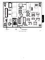
A13153
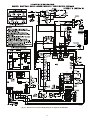
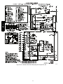
Fig. 14 -- 208/230--1--60 Connection Wiring Diagram Gas Inputs 40, 60 90 KBtu/hr
19
48VR-- A
A13154
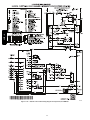
Fig. 15 Cont. -- 208/230--1--60 Ladder Wiring Diagram Gas Inputs 40, 60 90 KBtu/hr
20
48VR-- A
A13155
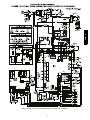
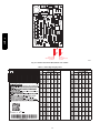
Fig. 15 -- 208/230--1--60 Connection Wiring Diagram Gas Inputs 115, 130 KBtu/hr
21
48VR-- A
A13156
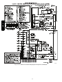
Fig. 16 Cont.-- 208/230--1--60 Ladder Wiring Diagram Gas Inputs 115, 130 KBtu/hr
22
48VR-- A
A13157
Fig. 16 -- 208/230--3--60 Connection Wiring Diagram Gas Inputs 40, 60, 90 KBtu/hr
23
48VR-- A
A13158
Fig. 17 Cont. -- 208/230--3--60 Ladder Wiring Diagram Gas Inputs 40, 60, 90 KBtu/hr
24
48VR-- A
A13159
Fig. 17 -- 208/230--3--60 Connection Wiring Diagram Gas Inputs 115, 130
25
48VR-- A
A13160
Fig. 18 Cont. -- 208/230--3--60 Ladder Wiring Diagram Gas Inputs 115, 130
26
Normal Operation
Airflow and Temperature Rise
The heating section for each size unit is designed and approved for
heating operation within the temperature--rise range(s) stamped on
the unit rating plate.
Tables 10 show the approved temperature rise range for each
heating input and stage, and the air delivery cfm at various
temperature rises for a given external static pressure. The heating
operation airflow must produce a temperature rise that falls within
the approved range for each heating stage.
Refer to Indoor Airflow and Airflow Adjustments section to adjust
heating airflow when required.
Gas Heating Sequence of Operation
(See Fig. 14, 16, 17 and unit wiring label.)
On a call for low stage heating, terminal W1 on the thermostat is
energized. On a call for high stage heating both terminals W1 and
W2 are energized. Regardless of the stage of the heating call, the
induced--draft motor is turned on to high speed for a 15 sec
pre--purge time. After the pre--purge, when the pressure switch
senses that sufficient combustion air is being moved by the
induced--draft motor, the ignition sequence begins. The IGC will
energize the sparker and the low stage gas valve solenoid. Upon
sensing flame, the IGC will check the heating call. If W2 is not
energized, the IGC will drop the induced--draft motor to low speed
and maintain the gas valve on low stage. If W2 is energized, the
IGC will maintain the induced--draft motor on high speed and
energize the high stage gas valve solenoid. Thirty sec after flame is
sensed the IGC will turn on the evaporator fan motor. If W2 is not
energized, the evaporator fan motor will run on low heat speed. If
W2 is energized, the evaporator fan motor will run on high heat
speed. After the call for heat is satisfied, the IGC will run the
evaporator fan motor an additional field--selectable time of 90, 120,
150, or 180 sec before shutting the evaporator fan motor off.
Limit Switches
Normally closed limit switch(es) (LS) complete the control circuit.
Should the leaving--air temperature rise above the maximum
allowable temperature, the limit switch opens and the control
circuit “breaks.” Any interruption in the control circuit instantly
closes the gas valve and stops gas flow to the burners. The blower
motor continues to run until LS resets.
When the air temperature at the limit switch drops to the
low--temperature setting of the limit switch, the switch closes and
completes the control circuit. The direct--spark ignition system
cycles and the unit returns to normal heating operation.
LED INDICATION
On
Off
2 Flashes
3 Flashes
4 Flashes
5 Flashes
6 Flashes
7 Flashes
8 Flashes
9 Flashes
NOTES:
1.This code indicates an internal processor fault that will reset itself in one
hr. Fault can be caused by stray RF signals in the structure or nearby. This
is a UL requirement.
2. LED indicates acceptable operation. Do not change ignition control
board.
3. When W is energized the burners will remain on for a minimum of 60 sec.
4. If more than one error code exists they will be displayed on the LED in
sequence.
Rollout Switch
The function of the rollout switch is to close the main gas valve in
the event of flame rollout. The switch is located above the main
burners. When the temperature at the rollout switch reaches the
maximum allowable temperature, the control circuit trips, closing
the gas valve and stopping gas flow to the burners. The indoor
(evaporator) fan motor (IFM) and induced draft motor continue to
run until switch is reset. The IGC LED will display FAULT CODE
7.
Step 3 — Start--up Cooling and Make Adjustments
Complete the required procedures given in the Pre--Start--Up
section before starting the unit. Do not jumper any safety devices
when operating the unit. Do not operate the compressor when the
outdoor temperature is below 40F (4.4C) (unless accessory
low--ambient kit is installed). Do not rapid--cycle the compressor.
Allow 5 minutes between on cycles to prevent compressor damage.
Checking Cooling Control Operation
Start and check the unit for proper control operation as follows:
1. Place room thermostat SYSTEM switch or MODE control
in OFF position. Observe that blower motor starts when
FAN mode is placed in FAN ON position and shuts down
when FAN MODE switch is placed in AUTO position.
2. Thermostat:
On a typical two stage thermostat, when the room temperature rises 1 or 2 degrees above the cooling control setting
of the thermostat, the thermostat completes the circuit
between thermostat terminal R and terminals Y1, O and G.
These completed circuits through the thermostat connect the
contactor coil (C) (through unit wire Y1) and indoor fan
board (through unit wire G) across the 24--v. secondary of
transformer (TRAN).
On a typical two stage thermostat, when the room temperature is several degrees above the cooling control setting of
the thermostat, the thermostat completes the circuit between
terminal R and terminals Y1, Y2, O and G.
3. When using an automatic changeover room thermostat
place both SYSTEM or MODE control and FAN mode
stitches in AUTO positions. Observe that unit operates in
Cooling mode when temperature control is set to “call for
Cooling” (below room temperature).
NOTE: Once the compressor has started and then has stopped, it
should not be started again until 5 minutes have elapsed.
IMPORTANT: Three--phase, scroll compressors are direction
oriented. Unit must be checked to ensure proper compressor
3--phase power lead orientation. If not corrected within 5 minutes,
27
48VR-- A
An LED (light--emitting diode) indicator is provided on the
integrated gas unit controller (IGC) to monitor operation. The IGC
is located by removing the control access panel (see Fig. 20).
During normal operation, the LED is continuously on (See Table 6
for error codes).
Table 6 – LED Indications
STATUS CODE
Normal Operation2
No Power or Hardware Failure
Limit Switch Fault
Flame Sense Fault
Four Consecutive Limit Switch Faults
Ignition Lockout Fault
Pressure Switch Fault
Rollout Switch Fault
Internal Control Fault
Temporary 1 hr auto reset1
48VR-- A
the internal protector will shut off the compressor. The 3--phase
power leads to the unit must be reversed to correct rotation. When
turning backwards, the difference between compressor suction and
discharge pressures will be minimal.
Indoor Airflow and Airflow Adjustments
!
CAUTION
Checking and Adjusting Refrigerant Charge
UNIT OPERATION HAZARD
The refrigerant system is fully charged with PuronR (R--410A)
refrigerant and is tested and factory sealed. Allow system to operate
a minimum of 15 minutes before checking or adjusting charge.
NOTE: Adjustment of the refrigerant charge is not required unless
the unit is suspected of not having the proper PuronR (R--410A)
charge.
A subcooling chart is attached to the inside of the compressor
access panel. (See Table 9 and Fig. 20.) The chart includes the
required liquid line temperature at given discharge line pressures
and outdoor ambient temperatures for high stage cooling.
An accurate thermocouple-- or thermistor--type thermometer, and a
gauge manifold are required when using the subcooling charging
method for evaluating the unit charge. Do not use mercury or small
dial--type thermometers because they are not adequate for this type
of measurement.
Failure to follow this caution may result in unit damage.
!
For cooling operation, the recommended airflow is 350 to
450 cfm for each 12,000 Btuh of rated cooling capacity. For
heating operation, the airflow must produce a temperature
rise that falls within the range stamped on the unit rating
plate.
NOTE: Be sure that all supply--and return--air grilles are open,
free from obstructions, and adjusted properly.
!
ELECTRICAL SHOCK HAZARD
Failure to follow this warning could result in personal
injury or death.
CAUTION
UNIT DAMAGE HAZARD
Failure to follow this caution may result in unit damage.
When evaluating the refrigerant charge, an indicated
adjustment to the specified factory charge must always be
very minimal. If a substantial adjustment is indicated, an
abnormal condition exists somewhere in the cooling system,
such as insufficient airflow across either coil or both coils.
IMPORTANT: When evaluating the refrigerant charge, an
indicated adjustment to the specified factory charge must always be
very minimal. If a substantial adjustment is indicated, an abnormal
condition exists somewhere in the cooling system, such as
insufficient airflow across either coil or both coils.
Proceed as follows:
1. Remove caps from low-- and high--pressure service fittings.
2. Using hoses with valve core depressors, attach low-- and
high--pressure gauge hoses to low-- and high--pressure
service fittings, respectively.
3. Start unit in high stage cooling mode and let unit run until
system pressures stabilize.
4. Measure and record the following:
a. Outdoor ambient--air temperature (F [C] db).
b. Liquid line temperature (F [C]).
c. Discharge (high--side) pressure (psig).
d. Suction (low--side) pressure (psig) (for reference only).
5. Using “Subcooling Charging Charts,” compare outdoor--air
temperature(F [C] db) with the discharge line pressure
(psig) to determine desired system operating liquid line
temperature (See Table 9).
6. Compare actual liquid line temperature with desired liquid
line temperature. Using a tolerance of 2F (1.1C), add
refrigerant if actual temperature is more than 2F (1.1C)
higher than proper liquid line temperature, or remove
refrigerant if actual temperature is more than 2F (1.1C)
lower than required liquid line temperature.
NOTE: If the problem causing the inaccurate readings is a
refrigerant leak, refer to the Check for Refrigerant Leaks section.
WARNING
Disconnect electrical power to the unit and install lockout
tag before changing blower speed(s).
This unit has independent fan speeds for low stage cooling and
high stage cooling. In addition, units have the field--selectable
capability to run an enhanced dehumidification (’DHUM’) speed
on high stage cooling (as low as 320CFM per ton). Coupled with
the improved dehumidification associated with low stage cooling,
the DHUM speed allows for a complete dehumidification solution
independent of cooling stage. Units also have independent fan
speeds for low stage gas heating and high stage gas heating. Table
7 shows the operation modes and the associated fan speeds with
each mode:
Table 7 – Operation Modes and Fan Speeds
208/230 VAC Models
OPERATION MODE
FAN SPEED TAP
CONNECTION
Low Stage Gas Heating
LO HEAT
High Stage Gas Heating
HI HEAT
Low Stage Cooling/Heat Pump
LO COOL
High Stage Cooling/Heat Pump
HI COOL
High Stage Enhanced
Dehumidification Cooling
DHUM
Continuous Fan
LO COOL
The evaporator fan motor is factory set to provide 5 different fan
speeds to choose from for the various operation modes. Models are
factory--shipped with 4 speed wires connected with one spare
speed wire available.
28
Black = High Speed
Orange = Med --- High Speed
Red = Med Speed
Pink = Med --- Low Speed
Blue = Low Speed
Using the Same Fan Speed for More than One Mode: Some fan
speeds are ideal for more than one mode of operation. It is
permissible to use a field--supplied jumper wire to connect one
speed tap wire to two or more speed connections on the ignition
board (IGC). Jumper wires must use 18 AWG wire with at least
2/64” insulation.
Cooling Sequence of Operation
a. Continuous Fan
(1.) Thermostat closes circuit R to G energizing the
blower motor for continuous fan. The indoor fan is
energized on low speed.
b. Cooling Mode
(1.) Low Stage: Thermostat closes R to G, R to Y1
and R to O. The compressor and indoor fan are
energized on low speed. The outdoor fan is also
energized.
(2.) High Stage: Thermostat closes R to G, R to Y1, R
to Y2 and R to O. The compressor and indoor fan
are energized on high speed. The outdoor fan is
also energized.
c. Heat Pump Mode
(1.) Low Stage: Thermostat closes R to G, R to Y1.
The compressor and indoor fan are energized on
low speed. The outdoor fan is also energized.
(2.) High Stage: Thermostat closes R to G, R to Y1, R
to Y2. The compressor and indoor fan are energized on high speed. The outdoor fan is also energized.
d. Defrost Mode
(1.) Outdoor Fan is disabled, thermostat closes R to O
and R to W1. Low stage gas heat tempers the leaving air. When defrost is complete, unit will return
to heating mode. If room thermostat is satisfied
during defrost, unit will shut down and restart in
defrost on next call for heat.
Selection of Proper Fan Speeds for Operation
Modes:
NOTE: All models are factory--shipped for nominal high stage
and low stage cooling airflow operation at minimum external static
pressure. Many models are factory--shipped for nominal high stage
and/or low stage gas heating airflow at minimum external static
pressure. Table 10 provides airflow data for higher external static
pressures.
Low Stage Gas Heating: Table 10 shows the suitability of each
speed for a given external static pressure for low stage gas heating.
Any speed/static combination that is outside the rise range is
marked “NA” and must not be used. The unit must operate within
the low stage gas heat rise range printed on the rating plate.
Connect the chosen fan speed wire to “LO HEAT” connection on
the IGC Board (see Fig. 18).
High Stage Gas Heating: Table 10 shows the suitability of each
speed for a given external static pressure for high stage gas heating.
Any speed/static combination that is outside the rise range is
marked “NA” and must not be used. The unit must operate within
the high stage gas heat rise range printed on the rating plate.
Connect the chosen fan speed wire to “HI HEAT” connection on
the IGC Board (see Fig. 18).
Low Stage Cooling/Heat Pump: Using Tables 11, 12, and 13,
and the nominal airflow for low stage cooling (Table 1) find the
external static pressure drops for wet coil, economizer, and filter,
and add them to dry coil measured on the system. Using this total
static pressure, use Table 10 to find the airflows available at the
total static pressure. Connect the chosen fan speed wire to “LO
COOL” connection on the IGC Board (see Fig. 18).
High Stage Cooling/Heat Pump:Using Tables 11, 12, and 13,
find the external static pressure drops for wet coil, economizer, and
filter, and add them to dry coil measured on the system. Using this
total static pressure, use Table 10 to find the airflows available at
the total static pressure. The speed chosen must provide airflow of
between 350 to 450 CFM per ton of cooling. Connect the chosen
fan speed wire to “HI COOL” connection on the IGC Board (See
Fig. 18).
High Stage Enhanced Dehumidification Cooling: Using the
total static pressure for selecting the high stage cooling speed, use
Table 10 to find lower speed/airflows available at that total static
pressure. All airflows highlighted in Table 10 are acceptable for
Dehum speed. The speed chosen must provide airflow of between
320 to 400 CFM per ton of cooling. Connect the chosen fan speed
wire to “DHUM” connection on the IGC Board (see Fig. 18).
To activate the high stage enhanced dehumidification cooling
mode, the shunt jumper in Fig. 18 must be moved from the No DH
to DH selection (See Fig. 18, close up).
Continuous Fan (All models): Continuous fan speed is the same
speed as Low Stage Cooling.
Step 4 — Defrost Control
Quiet Shift
Quiet Shift is a field--selectable defrost mode, which will eliminate
occasional noise that could be heard at the start of defrost cycle and
restarting of heating cycle. It is selected by placing DIP switch 3
(on defrost board) in ON position.
When Quiet Shift switch is placed in ON position, and a defrost is
initiated, the following sequence of operation will occur. Reversing
valve will energize, outdoor fan will turn off, compressor will turn
off for 30 sec and then turn back on to complete defrost. At the
start of heating after conclusion of defrost reversing valve will
de--energize, compressor will turn off for another 30 sec, and the
outdoor fan will stay off for 40 sec, before starting in the Heating
mode.
Defrost
The defrost control is a time/temperature control which includes a
field--selectable time period (DIP switch 1 and 2 on the board)
between defrost cycles of 30, 60, 90, or 120 minutes (factory set at
60 minutes). To initiate a forced defrost, two options are available
depending on the status of the defrost thermostat.
29
48VR-- A
Table 8 – Color Coding for Indoor Fan Motor Leads
GND
L2
L1
L2 HIGH LOW
CCH
P2
K4
D26
T2
R55
R54
D6
R57
C11
Q7
Q6
SST-A
D14
JW6
P3
D19
D28 D20
R67
D18
R66
D17
FS
R68
D11
C7
JW4
R61
Q5
R14
R15
R72
R73
D25
D8
R64
C4
HI
COOL
LO
COOL
K10
HI
HEAT
U1
R22
U3
R48
LO
HEAT
R33
R30
R12
R52
24VAC
C2
C3
JW11
D5
JW9
R1
R46
R49
D3
24VAC COM
R11
R3
R19
AN1
MOV1
3
AMP
R37
R16
R6
C1
P1
R40
R5
R25
K8
F1
K1
R18
R39
R42
R36
R21
R27
R24
R22
R51
R47
JW5
JW3
R45
R32
R29
R17
R38
R41
R35
R20
R26
R70
K2
D9
R43
R44
R2
D21
C10
D27
C5
D22
D23
K6
Q4
R63
R62
Z1
JW1
R71
K9
R65
1
DHUM
C6
R53
K12
K7
D15
D10
U2
CONT
R58
D16
COM
R59
HUM
R60
Q2
JW2
Q1
K11 D24
Pb
R13
MOTOR
COM
R69
C8
e1
R56
48VR-- A
D12
D13
HSCI
CEBD431094-02-RA
D7
Q3
C9
K3
SOL
ANSI Z21.20 AUTOMATIC
IGNITION SYSTEM
24VAC 50/60hZ 350Ma MAX.
MODEL CEPL131094-01-R
K5
T1
D1
D2
D4
J1
R28
R4
R34
R10
180
150
120
90
BLOWER
OFF DELAY
JW7
R7
R31
JW8
R9
JW10
P4
J2
DH
DH
Y2 Y1 G W1W2 C R DH
Shunt in no
dehumidification
position
DH
DH
DH
DH
Shunt in
dehumidification
position
A13017
Fig. 18 -- Interface Fan Board (IFB) 208/230 VAC Models
Table 9 – Subcooling Charging Chart
A13171
30
31
48VR(-,N)A24040
Unit
48VR-- A
Table 10 – Dry Coil Air Delivery* -- Horizontal and Downflow Discharge -- Unit 48VR--A 208/230 VAC Models
External Static Pressure (IN. W.C.)
Motor
Wire
0.1
0.2
0.3
0.4
0.5
0.6
0.7
0.8
Speed
Color
CFM
714
525
------------BHP
0.08
0.07
------------Low Stage Heat Rise oF
26
36
3
Low
Blue
NA
NA
NA
NA
NA
NA
(oC)
(15)
(20)
o
High Stage Heat Rise F
41
NA
NA
NA
NA
NA
NA
NA
(oC)
(23)
CFM
777
692
583
465
318
------BHP
0.09
0.10
0.10
0.11
0.12
------oF
Low
Stage
Heat
Rise
24
27
32
40
Med-Low1
Pink
NA
NA
NA
NA
(oC)
(13)
(15)
(18)
(22)
o
High Stage Heat Rise F
37
42
50
NA
NA
NA
NA
NA
(oC)
(21)
(23)
(28)
CFM
877
779
698
598
519
410
----BHP
0.12
0.12
0.13
0.14
0.15
0.15
----oF
15 - 45oF Low Stage,
Low
Stage
Heat
Rise
21
24
27
31
36
Medium4
Red
NA
NA
NA
20 - 50oF High Stage
(oC)
(12)
(13)
(15)
(17)
(20)
High Stage Heat Rise oF
33
37
42
49
NA
NA
NA
NA
(oC)
(18)
(21)
(23)
(27)
CFM
904
841
769
705
628
522
372
--BHP
0.16
0.17
0.17
0.18
0.19
0.19
0.20
--Low Stage Heat Rise oF
21
22
24
27
30
36
2
Med-High
Orange
NA
NA
(oC)
(12)
(12)
(14)
(15)
(17)
(20)
High Stage Heat Rise oF
32
35
38
41
46
NA
NA
NA
(oC)
(18)
(19)
(21)
(23)
(26)
CFM
1291
1206
1142
1081
1017
951
888
823
BHP
0.31
0.32
0.33
0.34
0.34
0.35
0.36
0.36
Low Stage Heat Rise oF
15
16
16
17
18
20
21
23
High
Black
(oC)
(8)
(9)
(9)
(10)
(10)
(11)
(12)
(13)
High Stage Heat Rise oF
23
24
25
27
29
31
33
35
(oC)
(13)
(13)
(14)
(15)
(16)
(17)
(18)
(20)
Heating Rise
Range
-----
-----
NA
NA
668
0.37
28
(16)
44
(24)
NA
NA
753
0.37
25
(14)
39
(21)
-----
NA
NA
-----
NA
NA
NA
-----
-----
NA
NA
NA
NA
NA
NA
NA
1
-----
0.9
-----
32
48VR(-,N)A24060
Unit
Table 10 -- Dry Coil Air Delivery* -- Horizontal and Downflow Discharge -- Unit 48VR--A 208/230 VAC Models (Cont)
External Static Pressure (IN. W.C.)
Motor
Wire
Heating Rise Range
0.1
0.2
0.3
0.4
0.5
0.6
0.7
0.8
Speed
Color
CFM
777
692
583
465
318
------BHP
0.09
0.10
0.10
0.11
0.12
------Low Stage Heat Rise oF
37
41
49
1
Low
Blue
NA
NA
NA
NA
NA
(oC)
(20)
(23)
(27)
o
High Stage Heat Rise F
NA
NA
NA
NA
NA
NA
NA
NA
(oC)
CFM
877
779
698
598
519
410
----BHP
0.12
0.12
0.13
0.14
0.15
0.15
----oF
Low
Stage
Heat
Rise
21
24
27
31
36
Med-Low3
Pink
NA
NA
NA
(oC)
(12)
(13)
(15)
(17)
(20)
o
High Stage Heat Rise F
33
37
42
49
NA
NA
NA
NA
(oC)
(18)
(21)
(23)
(27)
CFM
904
841
769
705
628
522
372
--BHP
0.16
0.17
0.17
0.18
0.19
0.19
0.20
--oF
25 - 55oF Low Stage,
Low
Stage
Heat
Rise
32
34
37
40
45
55
Medium2
Red
NA
NA
25 - 55oF High Stage
(oC)
(18)
(19)
(21)
(22)
(25)
(30)
High Stage Heat Rise oF
49
53
NA
NA
NA
NA
NA
NA
(oC)
(27)
(29)
CFM
1229
1171
1105
1049
980
913
838
775
BHP
0.28
0.30
0.30
0.31
0.32
0.33
0.33
0.34
Low Stage Heat Rise oF
26
27
29
31
34
37
Med-High4
Orange
NA
NA
(oC)
(14)
(15)
(16)
(17)
(19)
(20)
High Stage Heat Rise oF
36
38
40
42
45
49
53
NA
(oC)
(20)
(21)
(22)
(24)
(25)
(27)
(29)
CFM
1291
1206
1142
1081
1017
951
888
823
BHP
0.31
0.32
0.33
0.34
0.34
0.35
0.36
0.36
Low Stage Heat Rise oF
25
26
28
30
32
35
High
Black
NA
NA
(oC)
(14)
(15)
(16)
(17)
(18)
(19)
High Stage Heat Rise oF
34
37
39
41
44
47
50
54
(oC)
(19)
(20)
(22)
(23)
(24)
(26)
(28)
(30)
48VR-- A
NA
668
0.37
43
(24)
NA
NA
753
0.37
38
(21)
NA
-----
-----
516
0.33
55
(31)
NA
NA
679
0.34
42
(23)
NA
NA
NA
-----
-----
NA
NA
NA
NA
NA
NA
NA
1
-----
0.9
-----
33
48VR(-,N)A30040
Unit
48VR-- A
Table 10 -- Dry Coil Air Delivery* -- Horizontal and Downflow Discharge -- Unit 48VR--A 208/230 VAC Models (Cont)
External Static Pressure (IN. W.C.)
Motor
Wire
Heating Rise Range
0.1
0.2
0.3
0.4
0.5
0.6
0.7
0.8
Speed
Color
CFM
714
525
------------BHP
0.08
0.07
------------Low Stage Heat Rise oF
26
36
3
Low
Blue
NA
NA
NA
NA
NA
NA
(oC)
(15)
(20)
o
High Stage Heat Rise F
41
NA
NA
NA
NA
NA
NA
NA
(oC)
(23)
CFM
831
765
670
586
466
299
----BHP
0.11
0.12
0.12
0.13
0.13
0.14
----oF
Low
Stage
Heat
Rise
23
25
28
32
40
Med-Low1
Pink
NA
NA
NA
(oC)
(13)
(14)
(16)
(18)
(22)
o
High Stage Heat Rise F
35
38
43
50
NA
NA
NA
NA
(oC)
(19)
(21)
(24)
(28)
CFM
877
779
698
598
519
410
----BHP
0.12
0.12
0.13
0.14
0.15
0.15
----oF
15 - 45oF Low Stage,
Low
Stage
Heat
Rise
21
24
27
31
36
Medium4
Red
NA
NA
NA
20 - 50oF High Stage
(oC)
(12)
(13)
(15)
(17)
(20)
High Stage Heat Rise oF
33
37
42
49
NA
NA
NA
NA
(oC)
(18)
(21)
(23)
(27)
CFM
1139
1069
1012
937
870
786
724
626
BHP
0.22
0.23
0.24
0.24
0.25
0.26
0.26
0.27
Low Stage Heat Rise oF
17
18
19
20
22
24
26
30
Med-High2
Orange
(oC)
(9)
(10)
(10)
(11)
(12)
(13)
(14)
(17)
High Stage Heat Rise oF
26
27
29
31
33
37
40
47
(oC)
(14)
(15)
(16)
(17)
(19)
(21)
(22)
(26)
CFM
1531
1460
1382
1301
1209
1114
1003
890
BHP
0.53
0.52
0.50
0.48
0.46
0.44
0.42
0.40
Low Stage Heat Rise oF
16
17
19
21
High
Black
NA
NA
NA
NA
(oC)
(9)
(9)
(10)
(12)
High Stage Heat Rise oF
20
21
22
24
26
29
33
NA
(oC)
(11)
(12)
(12)
(13)
(15)
(16)
(18)
-----
-----
NA
629
0.35
30
(17)
46
(26)
NA
764
0.37
25
(14)
38
(21)
NA
381
0.28
NA
NA
512
0.27
37
(20)
NA
NA
NA
-----
-----
NA
NA
NA
NA
NA
NA
NA
1
-----
0.9
-----
34
48VR(-,N)A30060
Unit
Table 10 -- Dry Coil Air Delivery* -- Horizontal and Downflow Discharge -- Unit 48VR--A 208/230 VAC Models (Cont)
External Static Pressure (IN. W.C.)
Motor
Wire
Heating Rise Range
0.1
0.2
0.3
0.4
0.5
0.6
0.7
0.8
Speed
Color
CFM
777
692
583
465
318
------BHP
0.09
0.10
0.10
0.11
0.12
------Low Stage Heat Rise oF
37
41
49
3
Low
Blue
NA
NA
NA
NA
NA
(oC)
(21)
(23)
(27)
o
High Stage Heat Rise F
NA
NA
NA
NA
NA
NA
NA
NA
(oC)
CFM
831
765
670
586
466
299
----BHP
0.11
0.12
0.12
0.13
0.13
0.14
----oF
Low
Stage
Heat
Rise
34
37
43
49
Med-Low1
Pink
NA
NA
NA
NA
(oC)
(19)
(21)
(24)
(27)
o
High Stage Heat Rise F
54
NA
NA
NA
NA
NA
NA
NA
(oC)
(30)
CFM
1139
1069
1012
937
870
786
724
626
BHP
0.22
0.23
0.24
0.24
0.25
0.26
0.26
0.27
25 - 55oF Low Stage,
Low Stage Heat Rise oF
25
27
28
30
33
36
39
46
Medium2
Red
o
25 - 55 F High Stage
(oC)
(14)
(15)
(16)
(17)
(18)
(20)
(22)
(26)
High Stage Heat Rise oF
39
42
44
47
51
NA
NA
NA
(oC)
(22)
(23)
(24)
(26)
(28)
CFM
1229
1171
1105
1049
980
913
838
775
BHP
0.28
0.30
0.30
0.31
0.32
0.33
0.33
0.34
Low Stage Heat Rise oF
26
27
29
31
34
37
Med-High4
Orange
NA
NA
(oC)
(14)
(15)
(16)
(17)
(19)
(21)
High Stage Heat Rise oF
36
38
40
42
45
49
53
NA
(oC)
(20)
(21)
(22)
(23)
(25)
(27)
(29)
CFM
1531
1460
1382
1301
1209
1114
1003
890
BHP
0.53
0.52
0.50
0.48
0.46
0.44
0.42
0.40
Low Stage Heat Rise oF
26
28
32
High
Black
NA
NA
NA
NA
NA
(oC)
(14)
(16)
(18)
High Stage Heat Rise oF
29
30
32
34
37
40
44
50
(oC)
(16)
(17)
(18)
(19)
(21)
(22)
(24)
(28)
48VR-- A
NA
629
0.35
45
(25)
NA
NA
764
0.37
37
(21)
NA
381
0.28
512
0.27
516
0.33
55
(31)
NA
NA
679
0.34
42
(23)
NA
NA
NA
-----
-----
NA
NA
NA
NA
NA
NA
NA
1
-----
0.9
-----
35
48VR(-,N)A36060
Unit
48VR-- A
Table 10 -- Dry Coil Air Delivery* -- Horizontal and Downflow Discharge -- Unit 48VR--A 208/230 VAC Models (Cont)
External Static Pressure (IN. W.C.)
Motor
Wire
Heating Rise Range
0.1
0.2
0.3
0.4
0.5
0.6
0.7
0.8
Speed
Color
CFM
694
624
533
460
383
328
----BHP
0.05
0.05
0.06
0.07
0.07
0.08
----Low Stage Heat Rise oF
41
46
54
3
Low
Blue
NA
NA
NA
NA
NA
(oC)
(23)
(25)
(30)
o
High Stage Heat Rise F
NA
NA
NA
NA
NA
NA
NA
NA
(oC)
CFM
934
864
810
745
698
649
571
525
BHP
0.10
0.10
0.11
0.12
0.13
0.14
0.14
0.15
Low Stage Heat Rise oF
31
33
35
38
41
44
50
54
Med-Low1
Pink
(oC)
(17)
(18)
(20)
(21)
(23)
(24)
(28)
(30)
High Stage Heat Rise oF
48
52
55
NA
NA
NA
NA
NA
(oC)
(26)
(29)
(31)
CFM
1213
1169
1110
1065
1016
964
923
878
BHP
0.16
0.17
0.17
0.19
0.20
0.21
0.22
0.23
25 - 55oF Low Stage,
Low Stage Heat Rise oF
26
27
28
30
31
33
Medium4
Red
NA
NA
o
25 - 55 F High Stage
(oC)
(14)
(15)
(16)
(16)
(17)
(18)
High Stage Heat Rise oF
37
38
40
42
44
46
48
51
(oC)
(20)
(21)
(22)
(23)
(24)
(26)
(27)
(28)
CFM
1251
1198
1149
1104
1066
1017
970
932
BHP
0.19
0.21
0.21
0.23
0.24
0.25
0.26
0.27
Low Stage Heat Rise oF
25
26
27
28
29
31
Med-High2
Orange
NA
NA
(oC)
(14)
(14)
(15)
(16)
(16)
(17)
High Stage Heat Rise oF
36
37
39
40
42
44
46
48
(oC)
(20)
(21)
(22)
(22)
(23)
(24)
(25)
(27)
CFM
1466
1423
1384
1343
1308
1263
1219
1183
BHP
0.30
0.31
0.33
0.34
0.35
0.36
0.37
0.38
Low Stage Heat Rise oF
High
Black
NA
NA
NA
NA
NA
NA
NA
NA
(oC)
High Stage Heat Rise oF
30
31
32
33
34
35
37
38
(oC)
(17)
(17)
(18)
(18)
(19)
(20)
(20)
(21)
NA
NA
428
0.17
NA
NA
777
0.25
37
(20)
NA
NA
486
0.16
NA
NA
820
0.24
35
(19)
54
(30)
892
0.28
32
(18)
50
(28)
1145
0.40
25
(14)
39
(22)
839
0.29
34
(19)
53
(29)
1106
0.41
26
(14)
40
(22)
NA
1
-----
0.9
-----
36
48VR(-,N)A36090
Unit
Table 10 -- Dry Coil Air Delivery* -- Horizontal and Downflow Discharge -- Unit 48VR--A 208/230 VAC Models (Cont)
External Static Pressure (IN. W.C.)
Motor
Wire
Heating Rise Range
0.1
0.2
0.3
0.4
0.5
0.6
0.7
0.8
Speed
Color
CFM
1097
971
823
747
669
636
558
513
BHP
0.12
0.11
0.10
0.11
0.12
0.13
0.13
0.14
Low Stage Heat Rise oF
39
44
52
58
64
3
Low
Blue
NA
NA
NA
(oC)
(22)
(25)
(29)
(32)
(36)
o
High Stage Heat Rise F
61
NA
NA
NA
NA
NA
NA
NA
(oC)
(34)
CFM
934
864
810
745
698
649
571
525
BHP
0.10
0.10
0.11
0.12
0.13
0.14
0.14
0.15
Low Stage Heat Rise oF
46
50
53
58
62
Med-Low1
Pink
NA
NA
NA
(oC)
(26)
(28)
(29)
(32)
(34)
o
High Stage Heat Rise F
NA
NA
NA
NA
NA
NA
NA
NA
(oC)
CFM
1251
1198
1149
1104
1066
1017
970
932
BHP
0.19
0.21
0.21
0.23
0.24
0.25
0.26
0.27
Low Stage Heat Rise oF
36
37
39
40
42
44
46
35 - 65oF Low Stage,
Medium2
Red
NA
(oC)
(20)
(21)
(22)
(22)
(23)
(25)
(26)
o
35 - 65 F High Stage
High Stage Heat Rise oF
54
56
59
61
63
NA
NA
NA
(oC)
(30)
(31)
(33)
(34)
(35)
CFM
1451
1415
1372
1327
1287
1249
1212
1168
248.
BHP
0.29
0.30
0.31
0.32
0.35
0.36
0.37
59
Med-High4
Orange
Low Stage Heat Rise oF
35
37
NA
NA
NA
NA
NA
NA
(oC)
(20)
(20)
High Stage Heat Rise oF
46
48
49
51
52
54
56
58
(oC)
(26)
(26)
(27)
(28)
(29)
(30)
(31)
(32)
CFM
1466
1423
1384
1343
1308
1263
1219
1183
BHP
0.30
0.31
0.33
0.34
0.35
0.36
0.37
0.38
Low Stage Heat Rise oF
35
36
High
Black
NA
NA
NA
NA
NA
NA
(oC)
(20)
(20)
High Stage Heat Rise oF
46
47
49
50
52
53
55
57
(oC)
(26)
(26)
(27)
(28)
(29)
(30)
(31)
(32)
48VR-- A
1
412
0.16
NA
NA
428
0.17
NA
NA
839
0.29
51
(28)
NA
1094
0.39
39
(22)
62
(34)
1106
0.41
39
(22)
61
(34)
0.9
456
0.15
NA
NA
486
0.16
NA
NA
892
0.28
48
(27)
NA
1130
0.38
38
(21)
60
(33)
1145
0.40
38
(21)
59
(33)
37
48VR(-,N)A42060
Unit
48VR-- A
Table 10 -- Dry Coil Air Delivery* -- Horizontal and Downflow Discharge -- Unit 48VR--A 208/230 VAC Models (Cont)
External Static Pressure (IN. W.C.)
Motor
Wire
Heating Rise Range
0.1
0.2
0.3
0.4
0.5
0.6
0.7
0.8
Speed
Color
CFM
694
624
533
460
383
328
----BHP
0.05
0.05
0.06
0.07
0.07
0.08
----Low Stage Heat Rise oF
41
46
54
3
Low
Blue
NA
NA
NA
NA
NA
(oC)
(23)
(25)
(30)
o
High Stage Heat Rise F
NA
NA
NA
NA
NA
NA
NA
NA
(oC)
CFM
1076
1026
972
918
872
827
771
714
BHP
0.13
0.14
0.15
0.15
0.17
0.18
0.18
0.20
Low Stage Heat Rise oF
27
28
29
31
33
35
37
40
Med-Low1
Pink
(oC)
(15)
(15)
(16)
(17)
(18)
(19)
(21)
(22)
High Stage Heat Rise oF
41
43
46
48
51
54
NA
NA
(oC)
(23)
(24)
(25)
(27)
(28)
(30)
CFM
1213
1169
1110
1065
1016
964
923
878
BHP
0.16
0.17
0.17
0.19
0.20
0.21
0.22
0.23
Low Stage Heat Rise oF
26
27
28
30
31
33
25 - 55oF Low Stage,
Medium4
Red
NA
NA
(oC)
(14)
(15)
(16)
(16)
(17)
(18)
o
25 - 55 F High Stage
High Stage Heat Rise oF
37
38
40
42
44
46
48
51
(oC)
(20)
(21)
(22)
(23)
(24)
(26)
(27)
(28)
CFM
1451
1415
1372
1327
1287
1249
1212
1168
248.
BHP
0.29
0.30
0.31
0.32
0.35
0.36
0.37
59
Med-High2
Orange
Low Stage Heat Rise oF
NA
NA
NA
NA
NA
NA
NA
NA
(oC)
o
High Stage Heat Rise F
31
31
32
34
35
36
37
38
(oC)
(17)
(17)
(18)
(18)
(19)
(20)
(20)
(21)
CFM
1633
1590
1552
1518
1483
1444
1406
1372
BHP
0.41
0.43
0.44
0.45
0.47
0.48
0.49
0.50
Low Stage Heat Rise oF
High
Black
NA
NA
NA
NA
NA
NA
NA
NA
(oC)
o
High Stage Heat Rise F
27
28
29
29
30
31
32
32
(oC)
(15)
(16)
(16)
(16)
(17)
(17)
(18)
(18)
NA
NA
611
0.22
47
(26)
NA
777
0.25
37
(20)
1094
0.39
26
(15)
41
(23)
1303
0.53
NA
34
(19)
NA
NA
666
0.21
43
(24)
NA
820
0.24
35
(19)
54
(30)
1130
0.38
25
(14)
39
(22)
1340
0.51
NA
33
(18)
NA
1
-----
0.9
-----
38
48VR(-,N)A42090
Unit
Table 10 -- Dry Coil Air Delivery* -- Horizontal and Downflow Discharge -- Unit 48VR--A 208/230 VAC Models (Cont)
External Static Pressure (IN. W.C.)
Motor
Wire
Heating Rise Range
0.1
0.2
0.3
0.4
0.5
0.6
0.7
0.8
Speed
Color
CFM
1097
971
823
747
669
636
558
513
BHP
0.12
0.11
0.10
0.11
0.12
0.13
0.13
0.14
Low Stage Heat Rise oF
39
44
52
58
64
3
Low
Blue
NA
NA
NA
(oC)
(22)
(25)
(29)
(32)
(36)
o
High Stage Heat Rise F
61
NA
NA
NA
NA
NA
NA
NA
(oC)
(34)
CFM
1076
1026
972
918
872
827
771
714
BHP
0.13
0.14
0.15
0.15
0.17
0.18
0.18
0.20
Low Stage Heat Rise oF
40
42
44
47
49
52
56
60
Med-Low1
Pink
(oC)
(22)
(23)
(25)
(26)
(27)
(29)
(31)
(33)
High Stage Heat Rise oF
63
NA
NA
NA
NA
NA
NA
NA
(oC)
(35)
CFM
1251
1198
1149
1104
1066
1017
970
932
BHP
0.19
0.21
0.21
0.23
0.24
0.25
0.26
0.27
Low Stage Heat Rise oF
36
37
39
40
42
44
46
35 - 65oF Low Stage,
Medium
Red
NA
(oC)
(20)
(21)
(22)
(22)
(23)
(25)
(26)
o
35 - 65 F High Stage
High Stage Heat Rise oF
54
56
59
61
63
NA
NA
NA
(oC)
(30)
(31)
(33)
(34)
(35)
CFM
1451
1415
1372
1327
1287
1249
1212
1168
248.
BHP
0.29
0.30
0.31
0.32
0.35
0.36
0.37
59
Med-High2
Orange
Low Stage Heat Rise oF
35
37
NA
NA
NA
NA
NA
NA
(oC)
(20)
(20)
High Stage Heat Rise oF
46
48
49
51
52
54
56
58
(oC)
(26)
(26)
(27)
(28)
(29)
(30)
(31)
(32)
CFM
1633
1590
1552
1518
1483
1444
1406
1372
BHP
0.41
0.43
0.44
0.45
0.47
0.48
0.49
0.50
oF
Low
Stage
Heat
Rise
High4
Black
NA
NA
NA
NA
NA
NA
NA
NA
(oC)
o
High Stage Heat Rise F
41
42
43
44
45
47
48
49
(oC)
(23)
(24)
(24)
(25)
(25)
(26)
(27)
(27)
48VR-- A
NA
NA
611
0.22
NA
NA
666
0.21
64
(36)
NA
839
0.29
51
(28)
NA
1094
0.39
39
(22)
62
(34)
1303
0.53
NA
52
(29)
NA
892
0.28
48
(27)
NA
1130
0.38
38
(21)
60
(33)
1340
0.51
NA
50
(28)
NA
1
412
0.16
0.9
456
0.15
39
48VR(-,N)A48090
Unit
48VR-- A
Table 10 -- Dry Coil Air Delivery* -- Horizontal and Downflow Discharge -- Unit 48VR--A 208/230 VAC Models (Cont)
External Static Pressure (IN. W.C.)
Motor
Wire
Heating Rise Range
0.1
0.2
0.3
0.4
0.5
0.6
0.7
0.8
Speed
Color
CFM
1067
904
703
587
501
449
380
340
BHP
0.12
0.10
0.09
0.09
0.09
0.10
0.11
0.12
Low Stage Heat Rise oF
40
48
61
3
Low
Blue
NA
NA
NA
NA
NA
(oC)
(22)
(26)
(34)
o
High Stage Heat Rise F
63
NA
NA
NA
NA
NA
NA
NA
(oC)
(35)
CFM
1271
1229
1177
1121
1066
1027
974
942
BHP
0.19
0.20
0.21
0.23
0.24
0.25
0.26
0.27
Low Stage Heat Rise oF
35
36
38
40
42
44
46
Med-Low1
Pink
NA
(oC)
(19)
(20)
(21)
(22)
(23)
(25)
(25)
High Stage Heat Rise oF
53
55
57
60
63
NA
NA
NA
(oC)
(29)
(30)
(32)
(33)
(35)
CFM
1340
1299
1240
1191
1139
1091
1050
1001
BHP
0.22
0.23
0.24
0.25
0.26
0.28
0.29
0.30
oF
35 - 65oF Low Stage,
Low
Stage
Heat
Rise
35
36
38
39
41
43
Medium4
Red
NA
NA
35 - 65oF High Stage
(oC)
(19)
(20)
(21)
(22)
(23)
(24)
High Stage Heat Rise oF
50
52
54
57
59
62
64
NA
(oC)
(28)
(29)
(30)
(31)
(33)
(34)
(36)
CFM
1686
1650
1617
1576
1544
1503
1468
1433
BHP
0.42
0.44
0.45
0.46
0.48
0.49
0.51
0.52
Low Stage Heat Rise oF
2
Med-High
Orange
NA
NA
NA
NA
NA
NA
NA
NA
(oC)
High Stage Heat Rise oF
40
41
42
43
44
45
46
47
(oC)
(22)
(23)
(23)
(24)
(24)
(25)
(26)
(26)
CFM
1854
1837
1781
1784
1720
1698
1655
1625
BHP
0.56
0.57
0.60
0.59
0.62
0.63
0.64
0.66
Low Stage Heat Rise oF
High
Black
NA
NA
NA
NA
NA
NA
NA
NA
(oC)
High Stage Heat Rise oF
36
37
38
38
39
40
41
41
(oC)
(20)
(20)
(21)
(21)
(22)
(22)
(23)
(23)
44
(24)
1356
0.55
1393
0.53
43
(24)
NA
NA
NA
895
0.32
48
(27)
952
0.31
45
(25)
NA
NA
NA
50
(28)
1532
0.67
839
0.29
51
(28)
887
0.28
48
(27)
48
(27)
1578
0.67
NA
NA
NA
NA
NA
NA
1
-----
0.9
-----
40
48VR(-,N)A48115
Unit
Table 10 -- Dry Coil Air Delivery* -- Horizontal and Downflow Discharge -- Unit 48VR--A 208/230 VAC Models (Cont)
External Static Pressure (IN. W.C.)
Motor
Wire
Heating Rise Range
0.1
0.2
0.3
0.4
0.5
0.6
0.7
0.8
Speed
Color
CFM
1271
1229
1177
1121
1066
1027
974
942
BHP
0.19
0.20
0.21
0.23
0.24
0.25
0.26
0.27
Low Stage Heat Rise oF
44
45
47
50
52
54
57
59
1
Low
Blue
(oC)
(24)
(25)
(26)
(28)
(29)
(30)
(32)
(33)
High Stage Heat Rise oF
NA
NA
NA
NA
NA
NA
NA
NA
(oC)
CFM
1340
1299
1240
1191
1139
1091
1050
1001
BHP
0.22
0.23
0.24
0.25
0.26
0.28
0.29
0.30
oF
Low
Stage
Heat
Rise
42
43
45
47
49
51
53
56
Med-Low3
Pink
(oC)
(23)
(24)
(25)
(26)
(27)
(28)
(30)
(31)
High Stage Heat Rise oF
NA
NA
NA
NA
NA
NA
NA
NA
(oC)
CFM
1686
1650
1617
1576
1544
1503
1468
1433
BHP
0.42
0.44
0.45
0.46
0.48
0.49
0.51
0.52
oF
30 - 60oF Low Stage,
Low
Stage
Heat
Rise
33
34
35
35
36
37
38
39
Medium2
Red
30 - 60oF High Stage
(oC)
(18)
(19)
(19)
(20)
(20)
(21)
(21)
(22)
High Stage Heat Rise oF
52
53
54
55
56
58
59
NA
(oC)
(29)
(29)
(30)
(31)
(31)
(32)
(33)
CFM
1854
1837
1781
1784
1720
1698
1655
1625
BHP
0.56
0.57
0.60
0.59
0.62
0.63
0.64
0.66
Low Stage Heat Rise oF
30
30
31
31
32
33
34
34
Med-High
Orange
(oC)
(17)
(17)
(17)
(17)
(18)
(18)
(19)
(19)
High Stage Heat Rise oF
47
47
49
49
51
51
53
53
(oC)
(26)
(26)
(27)
(27)
(28)
(28)
(29)
(30)
CFM
1934
1900
1855
1815
1778
1737
1695
1656
BHP
0.59
0.61
0.62
0.64
0.65
0.67
0.68
0.70
Low Stage Heat Rise oF
30
31
31
32
33
34
4
High
Black
NA
NA
(oC)
(17)
(17)
(17)
(18)
(18)
(19)
High Stage Heat Rise oF
45
46
47
48
49
50
51
52
(oC)
(25)
(25)
(26)
(27)
(27)
(28)
(28)
(29)
48VR-- A
NA
NA
895
0.32
NA
NA
952
0.31
59
(33)
NA
1356
0.55
41
(23)
NA
1532
0.67
36
(20)
57
(32)
1528
0.68
37
(20)
57
(32)
NA
1393
0.53
40
(22)
NA
1578
0.67
35
(20)
55
(31)
1606
0.70
35
(19)
54
(30)
NA
1
839
0.29
0.9
887
0.28
41
48VR(-,N)A48130
Unit
48VR-- A
Table 10 -- Dry Coil Air Delivery* -- Horizontal and Downflow Discharge -- Unit 48VR--A 208/230 VAC Models (Cont)
External Static Pressure (IN. W.C.)
Motor
Wire
Heating Rise Range
0.1
0.2
0.3
0.4
0.5
0.6
0.7
0.8
Speed
Color
CFM
1271
1229
1177
1121
1066
1027
974
942
BHP
0.19
0.20
0.21
0.23
0.24
0.25
0.26
0.27
Low Stage Heat Rise oF
49
51
53
56
59
61
64
1
Low
Blue
NA
(oC)
(27)
(28)
(30)
(31)
(33)
(34)
(36)
o
High Stage Heat Rise F
NA
NA
NA
NA
NA
NA
NA
NA
(oC)
CFM
1340
1299
1240
1191
1139
1091
1050
1001
BHP
0.22
0.23
0.24
0.25
0.26
0.28
0.29
0.30
oF
Low
Stage
Heat
Rise
47
48
51
53
55
57
60
63
Med-Low3
Pink
(oC)
(26)
(27)
(28)
(29)
(31)
(32)
(33)
(35)
High Stage Heat Rise oF
NA
NA
NA
NA
NA
NA
NA
NA
(oC)
CFM
1686
1650
1617
1576
1544
1503
1468
1433
BHP
0.42
0.44
0.45
0.46
0.48
0.49
0.51
0.52
oF
35 - 65oF Low Stage,
Low
Stage
Heat
Rise
37
38
39
40
41
42
43
44
Medium2
Red
35 - 65oF High Stage
(oC)
(21)
(21)
(22)
(22)
(23)
(23)
(24)
(24)
High Stage Heat Rise oF
57
58
59
61
62
64
65(3
NA
(oC)
(32)
(32)
(33)
(34)
(35)
(35)
6)
CFM
1854
1837
1781
1784
1720
1698
1655
1625
BHP
0.56
0.57
0.60
0.59
0.62
0.63
0.64
0.66
Low Stage Heat Rise oF
35
35
36
37
38
39
Med-High
Orange
NA
NA
(oC)
(20)
(20)
(20)
(20)
(21)
(21)
High Stage Heat Rise oF
52
52
54
54
56
56
58
59
(oC)
(29)
(29)
(30)
(30)
(31)
(31)
(32)
(33)
CFM
1934
1900
1855
1815
1778
1737
1695
1656
BHP
0.59
0.61
0.62
0.64
0.65
0.67
0.68
0.70
Low Stage Heat Rise oF
35
35
36
37
38
4
High
Black
NA
NA
NA
(oC)
(19)
(20)
(20)
(21)
(21)
High Stage Heat Rise oF
50
50
52
53
54
55
57
58
(oC)
(28)
(28)
(29)
(29)
(30)
(31)
(31)
(32)
1
839
0.29
NA
NA
895
0.32
NA
NA
1356
0.55
46
(26)
NA
1532
0.67
41
(23)
63
(35)
1528
0.68
41
(23)
63
(35)
0.9
887
0.28
NA
NA
952
0.31
NA
NA
1393
0.53
45
(25)
NA
1578
0.67
40
(22)
61
(34)
1606
0.70
39
(22)
60
(33)
42
48VR(-,N)A60090
Unit
Table 10 -- Dry Coil Air Delivery* -- Horizontal and Downflow Discharge -- Unit 48VR--A 208/230 VAC Models (Cont)
External Static Pressure (IN. W.C.)
Motor
Wire
Heating Rise Range
0.1
0.2
0.3
0.4
0.5
0.6
0.7
0.8
Speed
Color
CFM
908
865
800
747
690
629
583
532
BHP
0.12
0.13
0.13
0.14
0.15
0.16
0.17
0.18
Low Stage Heat Rise oF
47
50
54
58
62
3
Low
Blue
NA
NA
NA
(oC)
(26)
(28)
(30)
(32)
(35)
o
High Stage Heat Rise F
NA
NA
NA
NA
NA
NA
NA
NA
(oC)
CFM
1415
1384
1340
1314
1270
1236
1192
1159
BHP
0.32
0.34
0.35
0.36
0.37
0.39
0.39
0.41
oF
Low
Stage
Heat
Rise
35
36
37
Med-Low4
Pink
NA
NA
NA
NA
NA
(oC)
(19)
(20)
(21)
High Stage Heat Rise oF
48
49
50
51
53
55
57
58
(oC)
(26)
(27)
(28)
(29)
(29)
(30)
(31)
(32)
CFM
1454
1405
1364
1316
1281
1234
1198
1147
BHP
0.34
0.35
0.36
0.37
0.38
0.40
0.41
0.42
oF
35 - 65oF Low Stage,
Low
Stage
Heat
Rise
35
36
37
Medium1
Red
NA
NA
NA
NA
NA
35 - 65oF High Stage
(oC)
(19)
(20)
(21)
High Stage Heat Rise oF
46
48
49
51
53
55
56
59
(oC)
(26)
(27)
(27)
(28)
(29)
(30)
(31)
(33)
CFM
1818
1770
1731
1693
1657
1621
1579
1546
BHP
0.56
0.57
0.59
0.60
0.62
0.63
0.64
0.66
Low Stage Heat Rise oF
2
Med-High
Orange
NA
NA
NA
NA
NA
NA
NA
NA
(oC)
High Stage Heat Rise oF
37
38
39
40
41
42
43
44
(oC)
(21)
(21)
(22)
(22)
(23)
(23)
(24)
(24)
CFM
2138
2084
2025
1967
1893
1829
1754
1678
BHP
0.98
0.95
0.93
0.90
0.86
0.84
0.80
0.76
Low Stage Heat Rise oF
High
Black
NA
NA
NA
NA
NA
NA
NA
NA
(oC)
High Stage Heat Rise oF
36
37
38
40
NA
NA
NA
NA
(oC)
(20)
(20)
(21)
(22)
48VR-- A
47
(26)
1475
0.68
NA
46
(25)
NA
42
(24)
1076
0.44
40
(22)
63
(35)
1056
0.45
41
(23)
64
(35)
1436
0.66
1116
0.42
38
(21)
60
(34)
1105
0.43
39
(22)
61
(34)
1505
0.67
45
(25)
1591
0.74
NA
NA
NA
NA
NA
NA
1
447
0.20
0.9
500
0.19
43
48VR(-,N)A60115
Unit
48VR-- A
Table 10 -- Dry Coil Air Delivery* -- Horizontal and Downflow Discharge -- Unit 48VR--A 208/230 VAC Models (Cont)
External Static Pressure (IN. W.C.)
Motor
Wire
Heating Rise Range
0.1
0.2
0.3
0.4
0.5
0.6
0.7
0.8
Speed
Color
CFM
1182
1137
1102
1053
1012
966
920
868
BHP
0.21
0.22
0.23
0.24
0.25
0.26
0.27
0.28
Low Stage Heat Rise oF
47
49
51
53
55
58
3
Low
Blue
NA
NA
(oC)
(26)
(27)
(28)
(29)
(31)
(32)
o
High Stage Heat Rise F
NA
NA
NA
NA
NA
NA
NA
NA
(oC)
CFM
1454
1405
1364
1316
1281
1234
1198
1147
BHP
0.34
0.35
0.36
0.37
0.38
0.40
0.41
0.42
oF
Low
Stage
Heat
Rise
38
40
41
42
44
45
47
49
Med-Low1
Pink
(oC)
(21)
(22)
(23)
(24)
(24)
(25)
(26)
(27)
High Stage Heat Rise oF
60
NA
NA
NA
NA
NA
NA
NA
(oC)
(33)
CFM
1818
1770
1731
1693
1657
1621
1579
1546
BHP
0.56
0.57
0.59
0.60
0.62
0.63
0.64
0.66
oF
30 - 60oF Low Stage,
Low
Stage
Heat
Rise
31
32
32
33
34
34
35
36
Medium2
Red
30 - 60oF High Stage
(oC)
(17)
(18)
(18)
(18)
(19)
(19)
(20)
(20)
High Stage Heat Rise oF
48
49
50
51
52
54
55
56
(oC)
(27)
(27)
(28)
(29)
(29)
(30)
(31)
(31)
CFM
1881
1849
1818
1793
1763
1729
1679
1610
BHP
0.67
0.69
0.70
0.71
0.72
0.73
0.73
0.71
Low Stage Heat Rise oF
30
30
31
31
32
32
33
35
4
Med-High
Orange
(oC)
(16)
(17)
(17)
(17)
(18)
(18)
(18)
(19)
High Stage Heat Rise oF
46
47
48
48
49
50
52
54
(oC)
(26)
(26)
(27)
(27)
(27)
(28)
(29)
(30)
CFM
2138
2084
2025
1967
1893
1829
1754
1678
BHP
0.98
0.95
0.93
0.90
0.86
0.84
0.80
0.76
Low Stage Heat Rise oF
31
32
33
High
Black
NA
NA
NA
NA
NA
(oC)
(17)
(18)
(18)
High Stage Heat Rise oF
41
42
43
44
46
48
50
52
(oC)
(23)
(23)
(24)
(25)
(26)
(26)
(28)
(29)
NA
NA
1056
0.45
NA
NA
1105
0.43
51
(28)
1436
0.66
39
(22)
1505
0.67
37
(21)
58
(32)
1523
0.68
37
(20)
57
(32)
1591
0.74
35
(19)
55
(30)
1479
0.65
38
(21)
59
(33)
1475
0.68
38
(21)
59
(33)
NA
NA
NA
NA
1
783
0.31
0.9
830
0.30
44
Notes:
* Air delivery values are without air filter and are for dry coil (See 48VR-A Wet Coil Pressure Drop Table).
1 Factory-shipped low stage cooling speed
2 Factory-shipped high stage cooling speed
3 Factory-shipped low stage gas heating speed
4 Factory-shipped high stage gas heating speed
Allowable High Stage Enhanced Dehumidification Cooling Speed
”NA” = Not allowed for particular heating speed
48VR(-,N)A60130
Unit
Table 10 -- Dry Coil Air Delivery* -- Horizontal and Downflow Discharge -- Unit 48VR--A 208/230 VAC Models (Cont)
External Static Pressure (IN. W.C.)
Motor
Wire
Heating Rise Range
0.1
0.2
0.3
0.4
0.5
0.6
0.7
0.8
Speed
Color
CFM
1182
1137
1102
1053
1012
966
920
868
BHP
0.21
0.22
0.23
0.24
0.25
0.26
0.27
0.28
Low Stage Heat Rise oF
53
55
57
59
62
65
3
Low
Blue
NA
NA
(oC)
(29)
(31)
(32)
(32)
(34)
(36)
o
High Stage Heat Rise F
NA
NA
NA
NA
NA
NA
NA
NA
(oC)
CFM
1454
1405
1364
1316
1281
1234
1198
1147
BHP
0.34
0.35
0.36
0.37
0.38
0.40
0.41
0.42
oF
Low
Stage
Heat
Rise
43
45
46
48
49
51
52
55
Med-Low1
Pink
(oC)
(24)
(25)
(26)
(26)
(27)
(28)
(29)
(30)
High Stage Heat Rise oF
NA
NA
NA
NA
NA
NA
NA
NA
(oC)
CFM
1818
1770
1731
1693
1657
1621
1579
1546
BHP
0.56
0.57
0.59
0.60
0.62
0.63
0.64
0.66
oF
35 - 65oF Low Stage,
Low
Stage
Heat
Rise
35
36
37
38
39
40
41
Medium2
Red
NA
35 - 65oF High Stage
(oC)
(20)
(20)
(21)
(21)
(21)
(22)
(23)
High Stage Heat Rise oF
53
54
55
57
58
59
61
62
(oC)
(29)
(30)
(31)
(31)
(32)
(33)
(34)
(34)
CFM
1881
1849
1818
1793
1763
1729
1679
1610
BHP
0.67
0.69
0.70
0.71
0.72
0.73
0.73
0.71
Low Stage Heat Rise oF
35
36
36
37
39
4
Med-High
Orange
NA
NA
NA
(oC)
(19)
(20)
(20)
(21)
(22)
High Stage Heat Rise oF
51
52
53
53
54
55
57
60
(oC)
(28)
(29)
(29)
(30)
(30)
(31)
(32)
(33)
CFM
2138
2084
2025
1967
1893
1829
1754
1678
BHP
0.98
0.95
0.93
0.90
0.86
0.84
0.80
0.76
Low Stage Heat Rise oF
36
37
High
Black
NA
NA
NA
NA
NA
NA
(oC)
(20)
(21)
High Stage Heat Rise oF
45
46
47
49
51
52
55
57
(oC)
(25)
(26)
(26)
(27)
(28)
(29)
(30)
(32)
48VR-- A
NA
NA
1056
0.45
59
(33)
NA
1436
0.66
44
(24)
NA
NA
1105
0.43
57
(31)
NA
1505
0.67
42
(23)
64
(35)
1523
0.68
41
(23)
63
(35)
1591
0.74
39
(22)
60
(33)
1479
0.65
42
(24)
65
(36)
1475
0.68
42
(24)
65
(36)
NA
1
783
0.31
0.9
830
0.30
45
1500-2200 CFM
16x24x1+18x24x1
(406x610x25+457x610x25)
(406x610x25+356x610x25)
--
--
3.0
3.5
4.0
5.0
0.03
600
2.0,
2.5
FILTER SIZE IN. (MM)
600-1400 CFM
12x20x1+12x20x1
(305x508x25+305x508x25)
1200-1800 CFM
16x24x1+14x24x1
COOLING
TONS
--
--
3.0
3.5
4.0
5.0
--
600
2.0,
2.5
1500-2200 CFM
16x24x1+18x24x1
(406x610x25+457x610x25)
(406x610x25+356x610x25)
600-1400 CFM
12x20x1+12x20x1
(305x508x25+305x508x25)
1200-1800 CFM
16x24x1+14x24x1
FILTER SIZE IN. (MM)
60
48
--
--
0.05
700
--
--
--
700
0.07
0.06
0.04
0.11
0.11
1300
0.06
0.10
0.08
1200
0.09
0.08
0.14
1400
0.10
0.07
0.06
0.09
1600
0.10
0.08
1500
STANDARD CFM (SCFM)
--
--
0.06
800
--
--
0.09
800
--
--
0.16
1000
--
--
0.18
1100
--
0.10
0.25
1200
--
--
0.08
900
--
--
0.10
1000
--
--
0.11
1100
--
0.07
0.13
1200
0.01
0.11
0.09
1700
--
0.11
0.28
--
0.12
0.30
0.17
0.14
--
--
0.08
0.14
--
0.09
0.16
0.04
0.09
--
0.08
0.12
0.11
1800
0.08
0.11
--
1700
0.18
0.16
--
1700
48VR-- A
0.06
0.10
--
STANDARD CFM (SCFM)
1300
1400
1500
1600
0.15
0.13
--
STANDARD CFM (SCFM)
1300
1400
1500
1600
Table 13 – Filter Pressure Drop Table (IN. W.C.)
--
--
0.14
900
Table 12 – Economizer with 1--in. Filter Pressure Drop (IN. W.C.)
0.05
0.05
COOLING
TONS
0.09
0.06
0.06
42
0.07
1100
36
1000
0.06
900
0.05
800
0.04
30
700
0.04
600
0.03
0.06
24
0.05
UNIT
SIZE
Table 11 – Wet Coil Pressure Drop (IN. W.C.)
0.10
0.12
--
1800
0.20
0.16
--
1800
0.09
0.13
1900
0.11
--
--
1900
0.21
--
--
1900
0.13
--
--
2000
0.22
--
--
2000
0.10
0.14
2000
0.14
--
--
2100
0.23
--
--
2100
0.12
2100
0.15
--
--
2200
0.23
--
--
2200
0.13
2200
MAINTENANCE
3. Inspect blower motor and wheel for cleanliness at the
beginning of each heating and cooling season. Clean when
necessary. For first heating and cooling season, inspect
blower wheel bi--monthly to determine proper cleaning
frequency.
4. Check electrical connections for tightness and controls for
proper operation each heating and cooling season. Service
when necessary.
5. Ensure electric wires are not in contact with refrigerant
tubing or sharp metal edges.
6. Check and inspect heating section before each heating
season. Clean and adjust when necessary.
7. Check flue hood and remove any obstructions, if necessary.
To ensure continuing high performance and to minimize the
possibility of premature equipment failure, periodic maintenance
must be performed on this equipment. This unit should be
inspected at least once each year by a qualified service person. To
troubleshoot unit, refer to Table 14--16, Troubleshooting Chart.
NOTE TO EQUIPMENT OWNER: Consult your local dealer
about the availability of a maintenance contract.
!
PERSONAL
HAZARD
WARNING
INJURY
AND
UNIT
DAMAGE
48VR-- A
Failure to follow this warning could result in personal
injury or death and unit component damage.
The ability to properly perform maintenance on this
equipment requires certain expertise, mechanical skills,
tools and equipment. If you do not possess these, do not
attempt to perform any maintenance on this equipment,
other than those procedures recommended in the Owner’s
Manual.
!
WARNING
ELECTRICAL SHOCK HAZARD
Failure to follow these warnings could result in personal
injury or death:
1. Turn off electrical power to the unit and install lock out
tag before performing any maintenance or service on this
unit.
2. Use extreme caution when removing panels and parts.
3. Never place anything combustible either on or in contact
with the unit.
Air Filter
IMPORTANT: Never operate the unit without a suitable air filter
in the return--air duct system. Always replace the filter with the
same dimensional size and type as originally installed. See Table 1
for recommended filter sizes.
Inspect air filter(s) at least once each month and replace
(throwaway--type) or clean (cleanable--type) at least twice during
each cooling season and twice during the heating season, or
whenever the filter becomes clogged with dust and lint.
Indoor Blower and Motor
NOTE: All motors are pre--lubricated. Do not attempt to lubricate
these motors.
For longer life, operating economy, and continuing efficiency,
clean accumulated dirt and grease from the blower wheel and
motor annually.
!
WARNING
ELECTRICAL SHOCK HAZARD
Failure to follow this warning could result in personal
injury or death.
Disconnect and tag electrical power to the unit before
cleaning the blower motor and wheel.
!
CAUTION
UNIT OPERATION HAZARD
Failure to follow this caution may result in improper
operation.
Errors made when reconnecting wires may cause improper
and dangerous operation. Label all wires prior to
disconnecting when servicing.
!
CAUTION
ENVIRONMENTAL HAZARD
Failure to follow this caution may result in environmental
pollution.
Remove and re--cycle all components or materials (i.e. oil,
refrigerant, etc) before unit final disposal.
The minimum maintenance requirements for this equipment are as
follows:
1. Inspect air filter(s) each month. Clean or replace when
necessary.
2. Inspect indoor coil, drain pan, and condensate drain each
cooling season for cleanliness. Clean when necessary.
To clean the blower motor and wheel:
1. Remove and disassemble blower assembly as follows:
a. Remove blower access panel (see Fig. 20).
b. Disconnect 5 pin plug and 4 pin plug from indoor
blower motor. Remove capacitor if required.
c. On all units remove blower assembly from unit.
Remove screws securing blower to blower partition and
slide assembly out. Be careful not to tear insulation in
blower compartment.
d. Ensure proper reassembly by marking blower wheel and
motor in relation to blower housing before disassembly.
e. Loosen setscrew(s) that secures wheel to motor shaft,
remove screws that secure motor mount brackets to
housing, and slide motor and motor mount out of
housing.
2. Remove and clean blower wheel as follows:
a. Ensure proper reassembly by marking wheel orientation.
b. Lift wheel from housing. When handling and/or
cleaning blower wheel, be sure not to disturb balance
weights (clips) on blower wheel vanes.
c. Remove caked--on dirt from wheel and housing with a
brush. Remove lint and/or dirt accumulations from
wheel and housing with vacuum cleaner, using soft
brush attachment. Remove grease and oil with mild
solvent.
d. Reassemble wheel into housing.
e. Reassemble motor into housing. Be sure setscrews are
tightened on motor shaft flats and not on round part of
shaft. Reinstall blower into unit. Reinstall capacitor.
46
6. Remove wires connected to gas valve. Mark each wire.
7. Remove the mounting screw that attaches the burner rack to
the unit base (See Fig. 19).
8. Partially slide the burner rack out of the unit (see Fig. 19
and 22). Remove ignitor and sensor wires at the burner assembly. Remove wires to rollout switch.
9. Slide the burner rack out of the unit (See Fig. 19 and 22).
10. To reinstall, reverse the procedure outlined above.
11. Check all connections for leaks.
f. Connect 5 pin plug and 4 pin plug to indoor blower
motor.
g. Reinstall blower access panel (see Fig. 20).
3. Restore electrical power to unit. Start unit and check for
proper blower rotation and motor speeds during heating and
cooling cycles.
Induced Draft (combustion air) Blower Assembly
Flue Gas Passageways
To inspect the flue collector box and upper areas of the heat
exchanger:
1. Remove the induced draft blower assembly according to
directions in the Induced Draft Blower Assembly section.
2. Remove the 11 screws holding the flue collector box cover
(See Fig. 19) to the heat exchanger assembly. Inspect the
heat exchangers.
3. Clean all surfaces, as required, using a wire brush.
Limit Switch
Remove blower access panel (see Fig. 20). Limit switch(es) are
located on the fan partition.
Burner Ignition
Unit is equipped with a direct spark ignition 100 percent lockout
system. Ignition module (IGC) is located in the control box (See
Fig. 19). Module contains a self--diagnostic LED. During
servicing, refer to label diagram or Table 6 in these instructions for
LED interpretation.
If lockout occurs, unit may be reset by either momentarily
interrupting power supply to unit or by turning selector switch to
OFF position at the thermostat.
!
WARNING
FIRE, EXPLOSION HAZARD
Failure to follow this warning could result in personal
injury, death or property damage.
Do not purge gas supply into the combustion chamber. Do
not use a match or other open flame to check for gas leaks.
Use a commercially available soap solution made
specifically for the detection of leaks to check all
connections. A fire or explosion may result causing
property damage, personal injury or loss of life.
Outdoor Coil, Indoor Coil, and Condensate Drain Pan
Inspect the condenser coil, evaporator coil, and condensate drain
pan at least once each year.
The coils are easily cleaned when dry; therefore, inspect and clean
the coils either before or after each cooling season. Remove all
obstructions, including weeds and shrubs, that interfere with the
airflow through the condenser coil.
Straighten bent fins with a fin comb. If coated with dirt or lint,
clean the coils with a vacuum cleaner, using the soft brush
attachment. Be careful not to bend the fins. If coated with oil or
grease, clean the coils with a mild detergent and water solution.
Rinse coils with clear water, using a garden hose. Be careful not to
splash water on motors, insulation, wiring, or air filter(s). For best
results, spray condenser coil fins from inside to outside the unit. On
units with an outer and inner condenser coil, be sure to clean
between the coils. Be sure to flush all dirt and debris from the unit
base.
Inspect the drain pan and condensate drain line when inspecting
the coils. Clean the drain pan and condensate drain by removing all
foreign matter from the pan. Flush the pan and drain trough with
clear water. Do not splash water on the insulation, motor, wiring, or
air filter(s). If the drain trough is restricted, clear it with a
“plumbers snake” or similar probe device.
Integrated
Gas Unit
Controller
(IGC)
Main Burners
At the beginning of each heating season, inspect for deterioration
or blockage due to corrosion or other causes. Observe the main
burner flames and adjust, if necessary.
Removal of Gas Train
To remove the gas train for servicing:
1. Shut off main gas valve.
2. Shut off power to unit and install lockout tag.
3. Remove control access panel (See Fig. 20).
4. Disconnect gas piping at unit gas valve.
5. Remove fan partition mounting bracket (2 screws located
on the left side of control compartment on the fan partition
panel). Slide bracket forward, bottom first, to remove. (See
Fig. 19.)
Auto Transformer
fuses used on 460
volt units only.
(Hidden)
Interface Fan
Board (IFB)
Induced Draft
Motor
Fan Partition
Mounting
Bracket
Flue
Collector
Box
Inducer
Blower
Housing
Burner
Rack
Mounting
Screw
Rollout
Switch
A09193
Fig. 19 -- Blower Housing and Flue Collector Box
47
48VR-- A
The induced--draft blower assembly consists of the inducer motor,
the blower housing, and the induced--draft blower wheel.
Clean periodically to assure proper airflow and heating efficiency.
Inspect blower wheel every fall and periodically during the heating
season. For the first heating season, inspect blower wheel
bimonthly to determine proper cleaning frequency.
To inspect blower wheel, remove draft hood assembly. Shine a
flashlight into opening to inspect wheel. If cleaning is required,
remove induced--draft blower assembly as follows:
1. Remove control access panel (See Fig. 20).
2. Remove the 5 screws that attach induced--draft blower assembly to the flue collector box cover.
3. Slide the assembly out of the unit. (See Fig. 22). Clean the
blower wheel. If additional cleaning is required, continue
with Steps 4 and 5.
4. To remove blower wheel, remove 2 setscrews.
5. To remove inducer motor, remove screws that hold the
inducer motor to the blower housing.
6. To reinstall, reverse the procedure outlined above.
Outdoor Fan
!
CAUTION
UNIT OPERATION HAZARD
Failure to follow this caution may result in damage to unit
components.
48VR-- A
Keep the condenser fan free from all obstructions to ensure
proper cooling operation. Never place articles on top of the
unit.
Compressor
Access Panel
Blower
Access
Panel
1. Remove 6 screws holding outdoor grille and motor to top
cover.
2. Turn motor/grille assembly upside down on top cover to
expose fan blade.
3. Inspect the fan blades for cracks or bends.
4. If fan needs to be removed, loosen setscrew and slide fan off
motor shaft.
5. When replacing fan blade, position blade as shown in Fig.
23.
6. Ensure that setscrew engages the flat area on the motor shaft
when tightening.
7. Replace grille.
Control
Access
Panel
A09211
Fig. 20 -- Unit Access Panels
Electrical Controls and Wiring
BLOWER
HOUSING
2 SETSCREWS
(HIDDEN)
Inspect and check the electrical controls and wiring annually. Be
sure to turn off the electrical power to the unit.
Remove access panels (see Fig. 20) to locate all the electrical
controls and wiring. Check all electrical connections for tightness.
Tighten all screw connections. If any smoky or burned connections
are noticed, disassemble the connection, clean all the parts, re--strip
the wire end and reassemble the connection properly and securely.
After inspecting the electrical controls and wiring, replace all the
panels. Start the unit, and observe at least one complete cooling
cycle to ensure proper operation. If discrepancies are observed in
operating cycle, or if a suspected malfunction has occurred, check
each electrical component with the proper electrical
instrumentation. Refer to the unit wiring label when making these
checks.
Refrigerant Circuit
C99085
Annually inspect all refrigerant tubing connections and the unit
base for oil accumulations. Detecting oil generally indicates a
refrigerant leak.
Fig. 21 -- Removal of Motor and Blower Wheel
!
WARNING
EXPLOSION, SAFETY AND ENVIRONMENTAL
HAZARD
Failure to follow this warning could result in
injury, death or property damage.
personal
System under pressure. Relieve pressure and recover all
refrigerant before system repair or final unit disposal. Use
all service ports and open all flow--control devices,
including solenoid valves.
A07680
Fig. 22 -- Burner Rack Removed
If oil is detected or if low cooling performance is suspected,
leak--test all refrigerant tubing using an electronic leak--detector,
halide torch, or liquid--soap solution. If a refrigerant leak is
detected, refer to the Check for Refrigerant Leaks section.
If no refrigerant leaks are found and low cooling performance is
suspected, refer to the Checking and Adjusting Refrigerant Charge
section.
48
FAN GRILLE
MOTOR
A
MOTOR SHAFT
A08505
MAX DISTANCE BETWEEN TOP OF FAN GRILLE AND BOTTOM OF FAN BLADE
IN.
6.3
6.3
7.6
7.6
7.6
7.6
24
30
36
42
48
60
MM
160
160
193
193
193
193
Fig. 23 -- Fan Blade Position
Gas Input
The gas input does not require checking unless improper heating
performance is suspected. If a problem exists, refer to the Start--Up
section.
Evaporator Airflow
The heating and/or cooling airflow does not require checking
unless improper performance is suspected. If a problem exists, be
sure that all supply-- and return--air grilles are open and free from
obstructions, and that the air filter is clean. When necessary, refer to
the Indoor Airflow and Airflow Adjustments section to check the
system airflow.
Defrost Thermostat
The defrost thermostat is usually located on the lowest liquid
leaving circuit of the left (See Fig. 24). The thermostat closes at
32_F (O_C) and opens at 65_F (18_C)
The defrost thermostat signals heat pump that conditions are right
for defrost or that conditions have changed to terminate defrost. It
is a thermally actuated switch clamped to outdoor coil to sense its
temperature. Normal temperature range is closed at 32_ 3_F (0
1.7_C) and open at 65_ 5_F (18 2.8_C).
FEEDER TUBE
STUB TUBE
DEFROST
THERMOSTAT
This unit uses both a hard shutoff, balance port TXV in the indoor
coil and a piston in each side of the outdoor coil. The TXV
maintains a constant superheat at the evaporator coil exit (cooling
mode) resulting in higher overall system efficiency.
Pressure Switches
Pressure switches are protective devices wired into control circuit
(low voltage). They shut off compressor if abnormally high or low
pressures are present in the refrigeration circuit. These pressure
switches are specifically designed to operate with Puron (R--410A)
systems. R--22 pressure switches must not be used as replacements
for the Puron (R--410A) system.
Loss of Charge Switch
This switch is located on the liquid line and protects against low
suction pressures caused by such events as loss of charge, low
airflow across indoor coil, dirty filters, etc. It opens on a pressure
drop at about 20 psig. If system pressure is above this, switch
should be closed. To check switch:
1. Turn off all power to unit.
2. Disconnect leads on switch.
3. Apply ohm meter leads across switch. You should have
continuity on a good switch.
NOTE: Because these switches are attached to refrigeration
system under pressure, it is not advisable to remove this device for
troubleshooting unless you are reasonably certain that a problem
exists. If switch must be removed, remove and recover all system
charge so that pressure gauges read 0 psig. Never open system
without breaking vacuum with dry nitrogen.
High-- Pressure Switch
C99029
Fig. 24 -- Defrost Thermostat Location
Puron Items
Metering Device (Thermostatic Expansion Valve &
Piston)
The high--pressure switch is located in the discharge line and
protects against excessive condenser coil pressure. It opens at 650
psig.
49
48VR-- A
“A”
SIZE
High pressure may be caused by a dirty outdoor coil, failed fan
motor, or outdoor air recirculation. To check switch:
1. Turn off all power to unit.
2. Disconnect leads on switch.
3. Apply ohm meter leads across switch. You should have
continuity on a good switch.
Copeland Scroll Compressor (Puron Refrigerant)
The compressor used in this product is specifically designed to
operate with Puron (R--410A) refrigerant and cannot be
interchanged.
The compressor is an electrical (as well as mechanical) device.
Exercise extreme caution when working near compressors. Power
should be shut off, if possible, for most troubleshooting techniques.
Refrigerants present additional safety hazards.
48VR-- A
!
WARNING
FIRE/EXPLOSION HAZARD
Failure to follow this warning could result in personal
injury or death and/or property damage.
Compressor Oil
The Copeland scroll compressor uses 3MAF POE oil. If additional
oil is needed, use Uniqema RL32--3MAF. If this oil is not
available, use Copeland Ultra 32 CC or Mobil Arctic EAL22 CC.
This oil is extremely hygroscopic, meaning it absorbs water
readily. POE oils can absorb 15 times as much water as other oils
designed for HCFC and CFC refrigerants. Take all necessary
precautions to avoid exposure of the oil to the atmosphere.
Servicing Systems on Roofs with Synthetic Materials
POE (polyolester) compressor lubricants are known to cause long
term damage to some synthetic roofing materials.
Exposure, even if immediately cleaned up, may cause
embrittlement (leading to cracking) to occur in one year or more.
When performing any service that may risk exposure of
compressor oil to the roof, take appropriate precautions to protect
roofing. Procedures which risk oil leakage include, but are not
limited to, compressor replacement, repairing refrigerant leaks,
replacing refrigerant components such as filter drier, pressure
switch, metering device, coil, accumulator, or reversing valve.
Synthetic Roof Precautionary Procedure
1. Cover extended roof working area with an impermeable
polyethylene (plastic) drip cloth or tarp. Cover an
approximate 10 X 10 ft. (3.1 m X 3.1 m) area.
2. Cover area in front of the unit service panel with a terry
cloth shop towel to absorb lubricant spills and prevent
run--offs, and protect drop cloth from tears caused by tools
or components.
3. Place terry cloth shop towel inside unit immediately under
component(s) to be serviced and prevent lubricant run--offs
through the louvered openings in the unit base.
4. Perform required service.
5. Remove and dispose of any oil contaminated material per
local codes.
Wear safety glasses and gloves when handling refrigerants.
Keep torches and other ignition sources away from
refrigerants and oils.
The scroll compressor pumps refrigerant throughout the system by
the interaction of a stationary and an orbiting scroll. The scroll
compressor has no dynamic suction or discharge valves, and it is
more tolerant of stresses caused by debris, liquid slugging, and
flooded starts. The compressor is equipped with a noise reducing
shutdown device and an internal pressure relief port. The pressure
relief port is a safety device, designed to protect against extreme
high pressure. The relief port has an operating range between 550
(26.34 kPa) and 625 psig (29.93 kPa) differential pressure.
!
WARNING
EXPLOSION,
HAZARD
ENVIRONMENTAL
SAFETY
Failure to follow this warning could result in personal
injury, death or equipment damage.
This system uses Puron (R--410A) refrigerant which has
higher operating pressures than R--22 and other refrigerants.
No other refrigerant may be used in this system. Gauge set,
hoses, and recovery system must be designed to handle
Puron. If you are unsure, consult the equipment
manufacturer.
Liquid Line Filter Drier
This filter drier is specifically designed to operate with Puron. Use
only factory--authorized components. Filter drier must be replaced
whenever the refrigerant system is opened. When removing a filter
drier, use a tubing cutter to cut the drier from the system. Do not
unsweat a filter drier from the system. Heat from unsweating will
release moisture and contaminants from drier into system.
Puron (R-- 410A) Refrigerant Charging
Refer to unit information plate and charging chart. Some R--410A
refrigerant cylinders contain a dip tube to allow liquid refrigerant to
flow from cylinder in upright position. For cylinders equipped
with a dip tube, charge Puron units with cylinder in upright
position and a commercial metering device in manifold hose.
Charge refrigerant into suction--line.
TROUBLESHOOTING
Refrigerant System
This information covers the refrigerant system of the 48VR--A,
including the compressor oil needed, servicing systems on roofs
containing synthetic materials, the filter drier and refrigerant
charging.
Use the Troubleshooting Guides (See Tables 14--16) if problems
occur with these units.
START--UP CHECKLIST
Use Start--Up checklist to ensure proper start--up procedures are
followed.
50
Y
P1
30
30
60
J1
P3
ON
DFT
QUIET
SHIFT
90
INTERVAL TIMER OFF
60
120
48VR-- A
T1
SPEEDUP
Fig. 25 -- Defrost Control
51
OF1
DFT
OF2
T2 C C O
O R W2 Y C
Defrost interval
DIP switches
Quiet
Shift
Speedup
Pins
A08020
48VR-- A
C99097
Fig. 26 -- Refrigerant Circuit
INDOOR COIL
OUTDOOR COIL
LCS
COMPRESSOR
ACCUMULATOR
TXV in Metering
Position
HP S
Bypass
Position
LEGEND
HPS – High Pressure Switch
LCS – Loss of Charge Switch
Accurater®Metering De vice
Arrow indicates direction of flo w
C03011
Fig. 27 -- Typical Heat Pump Operation, Cooling Mode
52
INDOOR COIL
OUTDOOR COIL
LCS
COMPRESSOR
HP S
Metering
Position
LEGEND
HPS – High Pressure Switch
LCS – Loss of Charge Switch
Accurater®Metering De vice
Arrow indicates direction of flo w
48VR-- A
ACCUMULATOR
TXV in Bypass
Position
C03012
Fig. 28 -- Typical Heat Pump Operation, Heating Mode
53
PURONR (R--410A) QUICK REFERENCE GUIDE
S Puron refrigerant operates at 50--70 percent higher pressures than R--22. Be sure that servicing equipment and replacement
components are designed to operate with Puron
S Puron refrigerant cylinders are rose colored.
S Recovery cylinder service pressure rating must be 400 psig, DOT 4BA400 or DOT BW400.
S Puron systems should be charged with liquid refrigerant. Use a commercial type metering device in the manifold hose when
charging into suction line with compressor operating
S Manifold sets should be minimum 700 psig high side and 180 psig low side with 550 psig low--side retard.
S Use hoses with minimum 700 psig service pressure rating.
S Leak detectors should be designed to detect HFC refrigerant.
S Puron, as with other HFCs, is only compatible with POE oils.
S Vacuum pumps will not remove moisture from oil.
48VR-- A
S Do not use liquid--line filter driers with rated working pressures less than 600 psig.
S Do not leave Puron suction line filter driers in line longer than 72 hrs.
S Do not install a suction--line filter drier in liquid line.
S POE oils absorb moisture rapidly. Do not expose oil to atmosphere.
S POE oils may cause damage to certain plastics and roofing materials.
S Wrap all filter driers and service valves with wet cloth when brazing.
S A factory approved liquid--line filter drier is required on every unit.
S Do NOT use an R--22 TXV.
S Never open system to atmosphere while it is under a vacuum.
S When system must be opened for service, recover refrigerant, evacuate then break vacuum with dry nitrogen and replace filter
driers. Evacuate to 500 microns prior to recharging.
S Do not vent Puron into the atmosphere.
S Observe all warnings, cautions, and bold text.
S All indoor coils must be installed with a hard shutoff Puron TXV metering device.
54
Table 14 – Troubleshooting Chart
Compressor and condenser fan will not start.
Compressor will not start but condenser fan
runs
CAUSE
REMEDY
Power failure
Call power company
Fuse blown or circuit breaker tripped
Replace fuse or reset circuit breaker
Defective contactor, transformer, or high--pressure,
loss--of--charge or low--pressure switch
Replace component
Insufficient line voltage
Determine cause and correct
Incorrect or faulty wiring
Check wiring diagram and rewire correctly
Thermostat setting too high
Lower thermostat temperature setting below
room temperature
Faulty wiring or loose connections in compressor circuit
Check wiring and repair or replace
Compressor motor burned out, seized, or
Determine cause
internal overload open
Replace compressor
Defective run/start capacitor, overload, start relay
Determine cause and replace
One leg of 3--phase power dead
Replace fuse or reset circuit breaker
Determine cause
Low input voltage
Determine cause and correct
Correct the direction of rotation by reversing the
Three--phase scroll compressor
makes excessive noise, and there may be a
low pressure differential.
Compressor cycles (other than normally satisfying thermostat)
Compressor operates continuously
Excessive head pressure
Head pressure too low
Excessive suction pressure
Suction pressure too low
Scroll compressor is rotating in the wrong direction
3--phase power leads to the unit. Shut down unit
to allow pressures to equalize.
Refrigerant overcharge or undercharge
Recover refrigerant, evacuate system, and recharge to capacities shown on rating plate
Defective compressor
Replace and determine cause
Insufficient line voltage
Determine cause and correct
Blocked outdoor coil
Determine cause and correct
Defective run/start capacitor
Determine cause and replace
Faulty outdoor fan motor or capacitor
Replace
Restriction in refrigerant system
Locate restriction and remove
Dirty air filter
Replace filter
Unit undersized for load
Decrease load or increase unit size
Thermostat temperature set too low
Reset thermostat
Low refrigerant charge
Locate leak, repair, and recharge
Air in system
Recover refrigerant, evacuate system, and recharge
Outdoor coil dirty or restricted
Clean coil or remove restriction
Dirty air filter
Replace filter
Dirty condenser coil
Clean coil
Refrigerant overcharged
Recover excess refrigerant
Air in system
Recover refrigerant, evacuate system, and recharge
Condenser air restricted or air short--cycling
Determine cause and correct
Low refrigerant charge
Check for leaks, repair, and recharge.
Restriction in liquid tube
Remove restriction
Refrigerant overcharged
Recover excess refrigerant
Dirty air filter
Replace filter
Low refrigerant charge
Check for leaks, repair and recharge
Metering device or low side restricted
Remove source of restriction
Insufficient evaporator airflow
Increase air quantity
Check filter–replace if necessary
Temperature too low in conditioned area
Reset thermostat
Outdoor ambient below 55F (13C)
Install low--ambient kit
Filter drier restricted
Replace filter
55
48VR-- A
SYMPTOM
Table 15 – Troubleshooting Guide–Heating
SYMPTOM
Burners will not ignite
48VR-- A
Inadequate heating
Poor flame characteristics
CAUSE
REMEDY
Water in gas line
Drain. Install drip leg.
No power to furnace
Check power supply fuses, wiring or circuit breaker.
No 24--v power supply to control circuit
Check transformer.
NOTE: Some transformers have internal over--current protection
that requires a cool--down period to reset.
Mis--wired or loose connections
Check all wiring and wire nut connections
Misaligned spark electrodes
Check flame ignition and sense electrode positioning.
Adjust as necessary.
No gas at main burners
1. Check gas line for air. Purge as necessary. NOTE: After purging
gas line of air, wait at least 5 minutes for any gas to dissipate before attempting to light unit.
2. Check gas valve.
Dirty air filter
Clean or replace filter as necessary
Gas input to furnace too low
Check gas pressure at manifold match with that on unit nameplate
Unit undersized for application
Replace with proper unit or add additional unit
Restricted airflow
Clean or replace filter. Remove any restriction.
Limit switch cycles main burners
Check rotation of blower, temperature rise of unit. Adjust as necessary.
Incomplete combustion results in: Aldehyde odors,
carbon monoxide, sooting flame, floating flame
1. Tighten all screws around burner compartment
2. Cracked heat exchanger. Replace.
3. Unit over--fired. Reduce input (change orifices or adjust gas line
or manifold pressure).
4. Check burner alignment.
5. Inspect heat exchanger for blockage. Clean as necessary.
Table 16 – Troubleshooting Guide–LED Status Codes
SYMPTOM
CAUSE
REMEDY
No Power or Hardware failure
(LED OFF)
Loss of power to control module (IGC)*.
Check 5--amp fuse son IGC*, power to unit, 24--v circuit breaker,
and transformer. Units without a 24--v circuit breaker have an
internal overload in the 24--v transformer. If the overload trips,
allow 10 minutes for automatic reset.
Limit switch faults
(LED 2 flashes)
High temperature limit switch is open.
Check the operation of the indoor (evaporator) fan motor. Ensure
that the supply--air temperature rise is in accordance with the
range on the unit nameplate. Clean or replace filters.
Flame sense fault
(LED 3 flashes)
The IGC* sensed flame that should not be present.
Reset unit. If problem persists, replace control board.
4 consecutive limit switch
faults
(LED 4 flashes)
Inadequate airflow to unit.
Check the operation of the indoor (evaporator) fan motor and that
supply--air temperature rise agrees with range on unit nameplate
information.
Ignition lockout fault
(LED 5 flashes)
Unit unsuccessfully attempted ignition for 15 minutes.
Check ignitor and flame sensor electrode spacing, gaps, etc.
Ensure that fame sense and ignition wires are properly terminated.
Verify that unit is obtaining proper amount of gas.
Pressure Switch fault
(LED 6 flashes)
Open pressure switch.
Verify wiring connections to pressure switch and inducer motor.
Verify pressure switch hose is tightly connected to both inducer
housing and pressure switch. Verify inducer wheel is properly
attached to inducer motor shaft. Verify inducer motor shaft is turning.
Rollout switch fault
(LED 7 flashes)
Rollout switch has opened.
Rollout switch will automatically reset, but IGC* will continue to
lockout unit. Check gas valve operation. Ensure that induced--draft
blower wheel is properly secured to motor shaft. Inspect heat
exchanger. Reset unit at unit disconnect.
Internal control fault
(LED 8 flashes)
Microprocessor has sensed an error in the software
or hardware.
If error code is not cleared by resetting unit power, replace the
IGC*.
Temporary 1 hr auto reset1
(LED 9 flashes)
Electrical interference impeding IGC software
Reset 24--v. to control board or turn thermostat off, then on again.
Fault will automatically reset itself in one (1) hour.
*WARNING
: If the IGC must be replaced, be sure to ground yourself to dissipate any electrical charge that my be present before handling new control
board. The IGC is sensitive to static electricity and my be damaged if the necessary precautions are not taken.
IMPORTANT: Refer to Table 15 ---Troubleshooting Guide ---Heating for additional troubleshooting analysis.
LEGEND
IGC—Integrated Gas Unit Controller
LED—Light---Emitting Diode
56
START--UP CHECKLIST
(Remove and Store in Job Files)
I. PRELIMINARY INFORMATION
MODEL NO.:
SERIAL NO.:
DATE:
TECHNICIAN:
III. START--UP
ELECTRICAL
SUPPLY VOLTAGE
COMPRESSOR AMPS
INDOOR (EVAPORATOR) FAN AMPS
TEMPERATURES
OUTDOOR (CONDENSER) AIR TEMPERATURE
DB
RETURN--AIR TEMPERATURE
DB
WB
COOLING SUPPLY AIR
DB
WB
HEAT PUMP SUPPLY AIR
GAS HEAT SUPPLY AIR
PRESSURES
GAS INLET PRESSURE
IN. W.C.
GAS MANIFOLD PRESSURE (HIGH STAGE)
IN. W.C.
GAS MANIFOLD PRESSURE (LOW STAGE)
REFRIGERANT SUCTION
PSIG, SUCTION LINE TEMP*
REFRIGERANT DISCHARGE
PSIG, LIQUID TEMP{
( ) VERIFY REFRIGERANT CHARGE USING CHARGING CHARTS
HIGH STAGE GAS HEAT TEMPERATURE RISE
RANGE (See Literature)
MEASURED TEMPERATURE RISE (HIGH STAGE)
LOW STAGE GAS HEAT TEMPERATURE RISE RANGE (208/230 VAC MODELS)
MEASURED LOW STAGE TEMPERATURE RISE RANGE (208/230 VAC MODELS)
* Measured at suction inlet to compressor
{ Measured at liquid line leaving condenser.
57
48VR-- A
II. PRESTART--UP (Insert check mark in box as each item is completed)
( ) VERIFY THAT ALL PACKING MATERIALS HAVE BEEN REMOVED FROM UNIT
( ) REMOVE ALL SHIPPING HOLD DOWN BOLTS AND BRACKETS PER INSTALLATION INSTRUCTIONS
( ) CHECK ALL ELECTRICAL CONNECTIONS AND TERMINALS FOR TIGHTNESS
( ) CHECK GAS PIPING FOR LEAKS (WHERE APPLICABLE)
( ) CHECK THAT INDOOR (EVAPORATOR) AIR FILTER IS CLEAN AND IN PLACE
( ) VERIFY THAT UNIT INSTALLATION IS LEVEL
( ) CHECK FAN WHEEL, AND PROPELLER FOR LOCATION IN HOUSING/ORIFICE AND SETSCREW TIGHTNESS
IN. W.C.
48VR-- A
Copyright 2013 Carrier Corp. S 7310 W. Morris St. S Indianapolis, IN 46231
Edition Date: 05/13
Manufacturer reserves the right to change, at any time, specifications and designs without notice and without obligations.
58
Catalog No: 48VR ---01SI
Replaces: New