1
SPLIT-TYPE, HEAT PUMP AIR CONDITIONERS
April 2012
TECHNICAL & SERVICE MANUAL
No. OC341
REVISED EDITION-F
R410A / R22
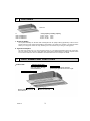
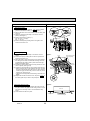
Indoor unit
[Model names]
PMFY-P06NBMU-E
PMFY-P08NBMU-E
PMFY-P12NBMU-E
PMFY-P15NBMU-E
[Service Ref.]
PMFY-P06NBMU-E
PMFY-P06NBMU-E#2
PMFY-P06NBMU-ER4
PMFY-P08NBMU-E
PMFY-P08NBMU-E#2
PMFY-P08NBMU-ER4
PMFY-P12NBMU-E
PMFY-P12NBMU-E#2
PMFY-P12NBMU-ER4
PMFY-P15NBMU-E
PMFY-P15NBMU-E#2
PMFY-P15NBMU-ER4
PMFY-P06NBMU-E1
PMFY-P06NBMU-ER3
PMFY-P06NBMU-ER5
PMFY-P08NBMU-E1
PMFY-P08NBMU-ER3
PMFY-P08NBMU-ER5
PMFY-P12NBMU-E1
PMFY-P12NBMU-ER3
PMFY-P12NBMU-ER5
PMFY-P15NBMU-E1
PMFY-P15NBMU-ER3
PMFY-P15NBMU-ER5
Revision:
• PMFY-P06/08/12/15NBMUER5 have been added in
REVISED EDITION-F.
• Some descriptions have
been modified.
• Please void OC341
REVISED EDITION-E.
NOTE:
• This manual describes
only service data of the
indoor units.
• RoHS compliant products
have <G> mark on the
spec name plate.
• For servicing RoHS compliant products, refer to the
RoHS PARTS LIST.
CONTENTS
1. TECHNICAL CHANGES....................... 2
2. FEATURES........................................... 3
3. PART NAMES AND FUNCTIONS........ 3
4. SPECIFICATION................................... 5
5. OUTLINES AND DIMENSIONS............ 9
6. WIRING DIAGRAM............................. 10
7. REFRIGERANT SYSTEM DIAGRAM....14
8. MICROPROCESSOR CONTROL....... 15
9. TROUBLESHOOTING........................ 22
10. DISASSEMBLY PROCEDURE........... 31
11. RoHS PARTS LIST............................. 35
INDOOR UNIT
Use the specified refrigerant only
Never use any refrigerant other than that specified.
Doing so may cause a burst, an explosion, or fire when the unit is being used, serviced, or disposed of.
Correct refrigerant is specified in the manuals and on the spec labels provided with our products.
We will not be held responsible for mechanical failure, system malfunction, unit breakdown or accidents caused
by failure to follow the instructions.
1
TECHNICAL CHANGES
→
→
→
→
PMFY-P06NBMU-ER4
PMFY-P08NBMU-ER4
PMFY-P12NBMU-ER4
PMFY-P15NBMU-ER4
PMFY-P06NBMU-ER5
PMFY-P08NBMU-ER5
PMFY-P12NBMU-ER5
PMFY-P15NBMU-ER5
• INDOOR CONTROLLER BOARD (I.B) has been changed. (S/W version up)
→
→
→
→
PMFY-P06NBMU-ER3
PMFY-P08NBMU-ER3
PMFY-P12NBMU-ER3
PMFY-P15NBMU-ER3
PMFY-P06NBMU-ER4
PMFY-P08NBMU-ER4
PMFY-P12NBMU-ER4
PMFY-P15NBMU-ER4
1. DRAIN PIPE has been changed.
2. JOINT SOCKET (FOR DRAIN PIPE) has been added.
→
→
→
→
PMFY-P06NBMU-E#2
PMFY-P08NBMU-E#2
PMFY-P12NBMU-E#2
PMFY-P15NBMU-E#2
PMFY-P06NBMU-ER3
PMFY-P08NBMU-ER3
PMFY-P12NBMU-ER3
PMFY-P15NBMU-ER3
• CONTROLLER BOARD (I.B) has been changed. (It is possible to extract a signal for an external heater.)
PMFY-P06NBMU-E1 →
PMFY-P08NBMU-E1 →
PMFY-P12NBMU-E1 →
PMFY-P15NBMU-E1 →
PMFY-P06NBMU-E#2
PMFY-P08NBMU-E#2
PMFY-P12NBMU-E#2
PMFY-P15NBMU-E#2
1. CONTROLLER BOARD (I.B) has been changed.
2. PANEL has been changed.
PMP-16BMU
→
PMP-16BMUW
(White : 0.98Y 8.99/0.63)
(Pure white : 6.4Y 8.9/0.4)
3. FAN MOTOR (MF) has been changed.
4. THERMISTORs (TH22, TH23) have been changed.
PMFY-P06NBMU-E
PMFY-P08NBMU-E
PMFY-P12NBMU-E
PMFY-P15NBMU-E
→
→
→
→
PMFY-P06NBMU-E1
PMFY-P08NBMU-E1
PMFY-P12NBMU-E1
PMFY-P15NBMU-E1
1. FAN MOTOR (MF) has been changed.
2. CONTROLLER BOARD (I.B) has been changed.
OC341F
2
2
FEATURES
Indoor Unit
Models
PMFY-P06NBMU-E
PMFY-P08NBMU-E
PMFY-P12NBMU-E
PMFY-P15NBMU-E
Cooling capacity
6,000 / 6,700
8,000 / 9,000
12,000 / 13,500
15,000 / 17,000
/ Heating capacity
Btu/h
Btu/h
Btu/h
Btu/h
1. Fresh Air Intake
Air recycled indefinitely can become stale and stagnant with air quality suffering significantly. Fresh air is the
answer and it is for this reason that the PMFY- series takes in air directly from outdoors. This fresh air intake
allows you to enjoy the comfort of crisp, refreshing air in the confines of your living or working space.
2. Light and Compact
The main unit weighs only 31 lb. and the panel merely 7 lb. This makes the PMFY- series one of the lightest in the industry. The unit size is also quite small, having been standardized to a strikingly compact 33-5/8
inch. All of this make the chore of installation and maintenance that much simpler and easier.
3
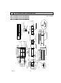
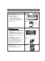
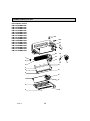
PART NAMES AND FUNCTIONS
Indoor Unit
Auto Air Swing Vane
Disperses airflow up and
down and adjusts the angle
of airflow direction.
Guide vane
Air flow can be changed to horizontal
by moving the guide vane to the left or right.
Horizontal Air Outlet
Filters
Remove dust and pollutants
from return air.
OC341F
Air intake
Returns air from room.
3
Wired remote controller
Once the controllers are set, the same operation mode can be repeated by simply pressing the ON/OFF button.
Note:
The phrase "Wired remote controller" in this manual refers only to the PAR-21MAA.
If you need any information for the other remote controller, please refer to either the installation manual or initial setting manual which are included in
remote controller's box.
ON/OFF button
Temperature setting buttons
Down
Fan Speed button
Up
Timer Menu button
(Monitor/Set button)
Filter
button
(<Enter> button)
Mode button (Return button)
TEMP.
ON/OFF
Set Time buttons
Check button (Clear button)
Back
Ahead
Timer On/Off button
(Set Day button)
Test Run button
MENU
BACK
MONITOR/SET
ON/OFF
FILTER
DAY
CHECK TEST
OPERATION
CLOCK
PAR-21MAA
Airflow Up/Down button
CLEAR
Louver button
(
Operation button)
To return operation
number
Opening the
cover
Ventilation button
( Operation button)
Built-in temperature sensor
To go to next operation
number
Display Section
For the purposes of this explanation,
all parts of the display are shown.
During actual operation, only
the relevant items will be lit.
Day-of-Week
“Sensor” indication
Shows the current day of the week.
Displays when the remote controller
sensor is used.
Time/Timer Display
Shows the current time, unless the simple or Auto Off
timer is set.
If the simple or Auto Off timer is set, the time to be
switched off is shown.
“Locked” indicator
Indicates that remote controller buttons have been locked.
Identifies the current operation
“Clean The Filter” indicator
Shows the operating mode, etc.
*Multilanguage display is available.
To be displayed on when it is time to
clean the filter.
TIME SUN MON TUE WED THU FRI SAT
TIMER
Hr
ON
AFTER
AFTER OFF
ERROR CODE
“Centrally Controlled” indicator
Indicates that operation from the
remote controller has been prohibited by a master controller.
FUNCTION
FILTER
°F°C
°F°C
WEEKLY
SIMPLE
AUTO OFF
ONLY1Hr.
Timer indicators
The indicator comes on if the corresponding timer is set.
Fan Speed indicator
Shows the selected fan speed.
“Timer is Off” indicator
Indicates that the timer is off.
Up/Down Air Direction indicator
Shows the direction of the
outcoming airflow.
“One Hour Only” indicator
Temperature Setting
Shows the target temperature.
OC341F
Displays if the airflow is set to
low or downward during COOL
or DRY mode. (Operation varies
according to model.)
The indicator goes off in one hour,
when the airflow direction also
changes.
Room Temperature display
Shows the room temperature. The room
temperature display range is 46~102°F.
The display blinks if the temperature
is less than 46°F or 102°F or more.
Louver display
Indicates the action of the swing louver.
Does not appear if the louver is not
running.
(Power On indicator)
Indicates that the power is on.
4
Ventilation indicator
Appears when the unit is running in
Ventilation mode.
4
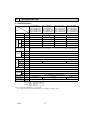
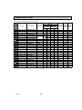
SPECIFICATION
4-1. SPECIFICATIONS
Service ref.
Item
PMFY-P06NBMU-E
PMFY-P06NBMU-E1
PMFY-P06NBMU-E#2
PMFY-P06NBMU-ER3
PMFY-P06NBMU-ER4
PMFY-P06NBMU-ER5
PMFY-P08NBMU-E
PMFY-P08NBMU-E1
PMFY-P08NBMU-E#2
PMFY-P08NBMU-ER3
PMFY-P08NBMU-ER4
PMFY-P08NBMU-ER5
PMFY-P12NBMU-E
PMFY-P12NBMU-E1
PMFY-P12NBMU-E#2
PMFY-P12NBMU-ER3
PMFY-P12NBMU-ER4
PMFY-P12NBMU-ER5
PMFY-P15NBMU-E
PMFY-P15NBMU-E1
PMFY-P15NBMU-E#2
PMFY-P15NBMU-ER3
PMFY-P15NBMU-ER4
PMFY-P15NBMU-ER5
V · HZ
Cooling capacity
Btu/h
6,000
8,000
12,000
15,000
Heating capacity
Btu/h
6,700
9,000
13,500
17,000
Cooling
kW
0.042
0.042
0.044
0.054
Heating
kW
0.042
0.042
0.044
0.054
Cooling
A
0.20
0.20
0.21
0.26
Heating
A
0.20
0.20
0.21
0.26
Exterior
(munsell symbol)
—
Unit : Galvanized sheets · Standard grilles : ABS resin acrylic coating
Munsell <0.98Y 8.99/0.63> (PMFY-P·NBMU-E(1)) / <6.4Y 8.9/0.4> (PMFY-P·NBMU-E#2/ER3/ER4/ER5)
Height
in.
9-1/16<1-3/16>
Dimensions Width
in.
31-15/16<39-3/8>
Depth
in.
15-9/16<18-1/2>
Heat exchanger
—
Cross fin
Fan × No
—
Line flow fan × 1
Air flow W3
CFM
External
static pressure
in W.G.
0
Fan motor
output
kW
0.028
Insulator
—
Polyethylene sheet
Air filter
F a n
Electric characteristic
Power
Single phase 208-230V 60Hz
Input
Current
230-250-280-300
250-280-300-320
—
PP honey comb fabric
Gas
side
Liquid
side
[in.
1/2
[in.
1/4
Field drain pipe size
[in.
1 O.D. (PVC pipe VP-20 connectable)
Noise level W3
dB
Product weight
Ib.
Pipe
dimensions
27-30-33-35
32-34-36-37
31<7>
Note 1. Rating conditions
Cooling: Indoor: D.B. 80°F W.B. 67°F
outdoor: D.B. 95°F W.B. 75°F
Heating: Indoor: D.B. 70°F
outdoor: D.B. 47°F W.B. 43°F
Note 2. The number indicated in < > is for the grille.
W 3. Air flow and the noise level are indicated as Low - Medium2 - Medium1 - High.
OC341F
5
270-300-340-370
33-35-37-39
4-2. ELECTRICAL PARTS SPECIFICATIONS
Service Ref.
Parts name
PMFY-P06NBMU-E
PMFY-P06NBMU-E1
PMFY-P06NBMU-E#2
Symbol
PMFY-P06NBMU-ER3
PMFY-P06NBMU-ER4
PMFY-P06NBMU-ER5
PMFY-P08NBMU-E
PMFY-P08NBMU-E1
PMFY-P08NBMU-E#2
PMFY-P08NBMU-ER3
PMFY-P08NBMU-ER4
PMFY-P08NBMU-ER5
PMFY-P12NBMU-E
PMFY-P12NBMU-E1
PMFY-P12NBMU-E#2
PMFY-P12NBMU-ER3
PMFY-P12NBMU-ER4
PMFY-P12NBMU-ER5
PMFY-P15NBMU-E
PMFY-P15NBMU-E1
PMFY-P15NBMU-E#2
PMFY-P15NBMU-ER3
PMFY-P15NBMU-ER4
PMFY-P15NBMU-ER5
Room temperature
thermistor
TH21
Resistance 30°F/15.8kΩ, 50°F/9.6kΩ, 70°F/6.0kΩ, 80°F/4.8kΩ, 90°F/3.9kΩ, 100°F/3.2kΩ
Liquid pipe thermistor
TH22
Resistance 30°F/15.8kΩ, 50°F/9.6kΩ, 70°F/6.0kΩ, 80°F/4.8kΩ, 90°F/3.9kΩ, 100°F/3.2kΩ
Gas pipe thermistor
TH23
Resistance 30°F/15.8kΩ, 50°F/9.6kΩ, 70°F/6.0kΩ, 80°F/4.8kΩ, 90°F/3.9kΩ, 100°F/3.2kΩ
Fuse
(Indoor controller board)
FUSE
250V 6A (PMFY-P·NBMU-E(1))
250V 6.3A (PMFY-P·NBMU-E#2/ER3/ER4/ER5)
Fan motor
MF
DC Brushless Motor
8-pole OUTPUT 28W
PN0H28-MB
Vane motor
MV
MSFJC 20M23
12V/380Ω
Drain pump
DP
PJV-1063
208-240V 50/60Hz
Drain sensor
DS
Linear expansion valve
LEV
DC12V Stepping motor drive
port dimension :3.2 (0~2000pulse)
EDM-40YGME
Power supply
terminal block
TB2
(L1, L2, GR) Rated to 330V 30A
+
Transmission
terminal block
TB5
(M1, M2, S) Rated to 250V 20A
+
MA-remote controller
terminal block
TB15
(1,2) Rated to 250V 10A
Thermistor resistance 30"F/6.3kΩ, 50"F/3.9kΩ, 70"F/2.5kΩ, 80"F/2.0kΩ, 90"F/1.6kΩ, 100"F/1.3kΩ
+
+Note : Refer to WIRING DIAGRAM for the supplied voltage.
OC341F
6
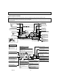
4-3. AIR CAPACITY TAKEN FROM OUTSIDE
PMFY-P·NBMU-E series are capable of taking air from outside. When taking air from outside, the duct fan is used.
The air capacity should be 20% or less of the airflow SPEC (Hi).
9-13/16
11-3/8
90
4-Ø1/8
4-1/4
5/16
Ø3-1
Ø4
/16
-13
Fresh air intake hole
(Knockout)
Fresh air intake hole
(Knockout)
(Unit: inch)
Service Ref.
Air flow (Hi)
Air capacity taken from outside
PMFY-P06NBMU-E/E1/E#2/ER3/ER4/ER5
300 CFM
60CFM
PMFY-P08NBMU-E/E1/E#2/ER3/ER4/ER5
320 CFM
64CFM
PMFY-P12NBMU-E/E1/E#2/ER3/ER4/ER5
320CFM
64CFM
PMFY-P15NBMU-E/E1/E#2/ER3/ER4/ER5
370CFM
74CFM
Operation in conjunction with duct fan (Booster fan)
Whenever the indoor unit is operating, the duct fan
operates.
(1) Connect the optional multiple remote controller
adaptor (PAC-SA88HA-E) to the connector CN51
on the indoor controller board.
(2) Drive the relay after connecting the 12V DC relay
between the Yellow and Orange connector lines.
(w)Use a relay of 1W or smaller.
MB: Electromagnetic switch power relay for duct fan.
X: Auxiliary relay (12V DC LY-1F)
CN51
on
indoor unit
board
E
C
A
Q
A
D
Multiple remote
controller adapter
PAC-SA88HA-E
Installation at site
Be sure to secure insulation
material by tape, etc.
Distance between indoor
controller board and relay
must be within 33 feet.
Multiple remote
controller adapter
PAC-SA88HA-E
Q…Designed amount of fresh air
intake
<CFM>
A…Static pressure loss of fresh air
intake duct system with air flow
amount Q
<in. W.G>
B…Forced static pressure at air conditioner inlet with air flow amount Q
<in. W.G>
C…Static pressure of booster fan with
air flow amount Q
<in. W.G>
D…Static pressure loss increase
amount of fresh air intake duct
system for air flow amount Q
<in. W.G>
E…Static pressure of indoor unit with
air flow amount Q
<in. W.G>
Qa…Estimated amount of fresh air
intake without D
<CFM>
Characteristic diagram of air capacity taken from outside of PMFY-P·NBMU-E
0.2
0.1
0
2 intake
-0.1
1 intake
-0.2
-0.3
-0.4
Q
Qa
0
10
20
30
40
Air flow (CFM)
OC341F
MB
Red
Brown
Indoor controller board
Static pressure (in.W.G.)
B
Q
Yellow
Orange +
1
Connector (5P)
CN51
A
0
~
Duct characteristics
at site
C
Curve in the
right graphs
Green
Indoor unit side
How to read curves
5
Be sure to secure insulation
material by tape, etc.
7
50
60
70
80
LINE
90
80
70
NC-70
60
NC-60
50
NC-50
40
NC-40
30
NC-30
20
NC-20
10
APPROXIMATE THRESHOLD OF HEARING
FOR CONTINUOUS NOISE
63
125
250
500
1000
2000
4000
PMFY-P08/12NBMU-E
PMFY-P08/12NBMU-E1
PMFY-P08/12NBMU-E#2
PMFY-P08/12NBMU-ER3
PMFY-P08/12NBMU-ER4
PMFY-P08/12NBMU-ER5
OCTAVE BAND SOUND PRESSURE LEVEL, dB (0 dB = 0.0002 μbar)
OCTAVE BAND SOUND PRESSURE LEVEL, dB (0 dB = 0.0002 μbar)
4-4. NOISE CRITERION CURVES
PMFY-P06NBMU-E
PMFY-P06NBMU-E1
NOTCH SPL(dB)
PMFY-P06NBMU-E#2
35
High
Medium1
33
PMFY-P06NBMU-ER3
30
Medium2
PMFY-P06NBMU-ER4
Low
27
PMFY-P06NBMU-ER5
8000
OCTAVE BAND SOUND PRESSURE LEVEL, dB (0 dB = 0.0002 μbar)
NOTCH SPL(dB)
39
High
Medium1
37
35
Medium2
Low
33
LINE
90
80
70
NC-70
60
NC-60
50
NC-50
40
NC-40
30
NC-30
20
10
APPROXIMATE
THRESHOLD OF
HEARING FOR
CONTINUOUS
NOISE
63
BAND CENTER FREQUENCIES, Hz
PMFY-P15NBMU-E
PMFY-P15NBMU-E1
PMFY-P15NBMU-E#2
PMFY-P15NBMU-ER3
PMFY-P15NBMU-ER4
PMFY-P15NBMU-ER5
NOTCH SPL(dB)
37
High
Medium1
36
34
Medium2
Low
32
125
NC-20
250
500
1000
2000
4000
8000
BAND CENTER FREQUENCIES, Hz
LINE
90
UNIT
80
CEILING
70
NC-70
60
NC-60
50
5ft
NC-50
40
NC-40
MICROPHONE
30
NC-30
20
10
APPROXIMATE
THRESHOLD OF
HEARING FOR
CONTINUOUS
NOISE
63
125
OC341F
NC-20
250
500
1000
2000
4000
BAND CENTER FREQUENCIES, Hz
8000
8
8-1/2(470)
Outer side of grille
16-15/16(430)
Ceiling opening
Ceiling panel
13/16(20)
Ceiling
Drain pan
panel
Same line
(3-3/8(96))
1-25/32(45)
1-11/16(43)
1-13/18(46)
1-1/32(26)
Lower view
7-7/8
(200)
Drain pan
:1-31/32(:50)
29-7/8(759)
Panel(grille):PMP-16BMU(W)
23-5/8(600)
13/16(20)
7-7/8
(200)
31-15/16(812)
Air outlet(lower)
13/16(20)
39-3/8(1000) Outer side of grille
Front
(2-3/16(56))
Drainage pipe
PVC pipe:
[ޓޓޓOD
:31/32(:25)]
VP-20
13/16(20)
1-25/32(45)
1-1/8(28)
1-1/8(28)
15-9/16(395)
11-7/8(302)
10(254)
13-3/8(340)
Suspension bolt pitch
Refrigirant
pipe(liquid)
OD:1/4(:6.35)
5-9/16(140)
Left side
6-15/16(176)
3-3/8(96)
11/16(17.5)
11/16(17.5)
7-13/16
(230)
(198)
Refrigirant pipe(gas)
OD:1/2(:12.7)
9-1/16
13/16(20)
(13/32(10))
Outer line of grille
2-1/16(53)
1-1/32(26)
2-15/18(74.5)
13/16(20)
1-3/16(30)
Terminal block for
remote-controller
Elect box
Center of unit
31-15/18(811) Suspension bolt pitch
29-7/8(759)
1-9/16(40)
2-3/8(60)
18-1/2(470)
outer side of grille
9-3/8(247)
Terminal block for power supply
Terminal block for transmission
Right side
pipe cover
Liquid pipe
Gas pipe
Knockout
Panel(grille):PMP-16BMU(W)
Suspension bolt(M10 or W3/8)
9-13/16
(250)
90°
Flesh air intake hole
11-3/8
(288.5)
:4-1
3/16
(:12
2)
00)
/16(:1
:3-15
4-:1/8(:2.8) Burring hole
OD:1-11/16(:43)
1/4F(:6.35)
1/2F(:12.7)
PVC pipe:VP-20[OD:31/32(:25)
Details of fresh air intake hole
Drainage piping
Refrigerant
piping
Installation space required around indoor unit
2-11/16(69)
39-3/8(1000) Outer side of grille
37-13/16(960) Ceiling opening
4-5/16(110)
13/16(20)
2-15/18(74.5)
9-1/16(230)
9-1/2(235)
Top
or more
9
Mounting plate
(110)
OC341F
4-5/16
5
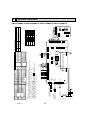
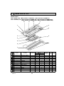
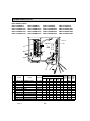
OUTLINES AND DIMENSIONS
PMFY-P06NBMU-E/E1/E#2/ER3/ER4/ER5
PMFY-P08NBMU-E/E1/E#2/ER3/ER4/ER5
PMFY-P12NBMU-E/E1/E#2/ER3/ER4/ER5
PMFY-P15NBMU-E/E1/E#2/ER3/ER4/ER5
Unit : inch (mm)
4-4/16(108)
<+2>
TO NEXT INDOOR UNIT
PULL BOX
FUSE(15A)
BREAKER
(15A)
L1
L2
GR
POWER SUPPLY
~ / N 208—230V 60Hz
TO OUTDOOR UNIT
BC CONTROLLER
REMOTE CONTROLLER
DC24-30V
2
1
TB15
TB2
MF
5
GRN / YLW
RED
BLU
S(SHIELD) TB5
M2
M1
TO MA-REMOTE
CONTROLLER
DC8.7-13V
BLU
BLU
ORN
ORN
(BLU)
(M-NET)
CN2M
LED2
CN3A
(BLU)
LED1
6
5
4 FAN
3 (WHT)
2
1
1
2
1
2
3
I.B
2 1
(BLK)
GAS
CN29
(WHT)
DRAIN
CN31
TH23
3 2 1
DS
2 1
TH21
CND
(RED)
FUSE
250V
6A
LEV
(WHT)
LEV
CN60
T
MV
1 2 3 4 5
1
(GRN)
VANE
CN6V
X1
DP
1 2 3
X1
6 5 4 3 2 1
(GRN)
REMOTE
INDICATION
CN52
1 5
(WHT)
CENTRALLY
CONTROL
CN51
5
6 5 4 3 2 1
6
BLU
BRN
ORN
YLW
RED
WHT
3 2 1
(WHT) (RED)
LIQUID INTAKE
CN21 CN20
2 1
TH22
BRN
RED
ORN
YLW
GRN
Note
1. At servicing for outdoor unit, always follow the wiring diagram of outdoor unit.
2. In case of using MA-Remote controller, please connect to TB15. (Remote controller wire is non-polar.)
3. In case of using M-NET, please connect to TB5. (Transmission wire is non-polar.)
4. Symbol [S] of TB5 is the shield wire connection.
5. Symbols used in wiring diagram above are,
: terminal block,
:connecter.
6. The setting of the SW2, SW3 dip switches differs in the capacity. For the detail, refer to fig. +1.
7.Please set the switch SW5 according to the power supply voltage.
A.B
Address board
Mode selection
SW1 Switch
Voltage selection
SW5
Address setting 1s digit
SW11
Address setting 10ths digit
SW12
SW14
Branch No.
TH23
TH22
Name
Room temp. detection
(32˚F/15k, 77˚F/5.4k)
Pipe temp. detection / Liquid
(32˚F/15k, 77˚F/5.4k)
Pipe temp. detection / Gas
(32˚F1/15k, 77˚F/5.4k)
2 1
(WHT)
CNP
CN25
2 1
CN27
ON
OFF
ON
OFF
ON
OFF
P08
P12
P15
123456
123456
123456
123456
SW2
ON
OFF
ON
OFF
ON
OFF
ON
OFF
(RED)
ADDRESS
CN42
See fig. +1
(WHT)
REMOTE
SWITCH
CN32
4
3
2
1
(RED)
ADDRESS
CN81
3
1
8
7
6
5
4
3
2
1
4
8
SW3
(RED)
ADDRESS
CN43
4 3 2 1
0
(RED)
ADDRESS
CN82
8 7 6 5 4 3 2 1
1 2 3 4 5 6 7 8 910
1 2 3 4 5 6 7 8 910
1 2 3 4 5 6 7 8 910
1 2 3 4 5 6 7 8 910
A.B
(+2) Use copper supply wire.
ON
OFF
P06
Models
<fig. +1>
LED on indoor board for service
Mark
Meaning
Function
Main power supply (Indoor unit:208-230V)
LED1 Main power supply
Power on → Lamp is lit.
Power supply for
Power supply for MA-Remote controller
LED2
MA-Remote controller on → Lamp is lit.
SW3
Symbol
TH21
Thermistor
SW4
SW2
1 2 34 5
1 2 3 4 5 6 1 2 3 4 5 6 7 8 910
Name
Drain pump
Aux.relay
Transformer
Power supply (I.B)
Power supply (I.B)
Fan motor (with inner thermo)
Vane motor
Drain pump
Drain sensor
Linear expansion valve
Terminal
Power supply
Transmission
block
MA-Remote Controller
ON
OFF
ON
OFF
Symbol
X1
T
LED1
LED2
MF
MV
DP
DS
LEV
TB2
TB5
TB15
SW5
Name
Indoor controller board
Connector
Humidifier
Damper
Remote switch
Centrally control
Remote Indication
Switch
Capacity code
Mode selection
Model selection
Varistor
Fuse (6A / 250V)
SW1
Symbol
I.B
CN25
CN27
CN32
CN51
CN52
SW2
SW3
SW4
ZNR
FUSE
230V
208V
0
0
[Legend]
1 2 3 4 5 6 7 8 910
ON
OFF
SWC SW14
SW12 SW11
BRANCH
No.
10
1s
DIGIT
OC341F
10ths
DIGIT
6
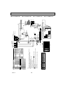
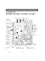
WIRING DIAGRAM
PMFY-P06NBMU-E PMFY-P08NBMU-E PMFY-P12NBMU-E PMFY-P15NBMU-E
Name
Room temp. detection
(32˚F/15k, 77˚F/5.4k)
Pipe temp. detection / Liquid
(32˚F/15k, 77˚F/5.4k)
Pipe temp. detection / Gas
(32˚F/15k, 77˚F/5.4k)
<+2>
TO NEXT INDOOR UNIT
PULL BOX
FUSE
(15A)
BREAKER
(15A)
POWER SUPPLY
~ / N 208-230V 60Hz
TO OUTDOOR UNIT
BC CONTROLLER
REMOTE CONTROLLER
DC24-30V
TO MA-REMOTE
CONTROLLER
DC8.7-13V
GR
L2
L1
TB2
MF
(SHIELD)
GRN / YLW
BLU
RED
MS
3~
S
M2
M1
TB5
2
TB15
1
BLU
BLU
ORN
ORN
LED2
CN3A
(BLU)
t°
(WHT)
LED1
6
3 FAN
1
1 (BLU)
(M-NET)
2 CN2M
3
1
I.B
1
(WHT)
DRAIN
CN31
3
DS
t°
2 1
(BLK)
GAS
CN29
TH23
2 1
t°
2 1
TH21
U
1
FUSE
CND 3
(RED)
(WHT) (RED)
LIQUID INTAKE
CN21 CN20
t°
TH22
6
1
(WHT) 1
CENTRALLY
CONTROL
CN51
5
(WHT)LEV
CN60
T
5
M
1
M
BRN
RED
BLU
ORN
YLW
WHT
MV
5
(GRN) 1
REMOTE
INDICATION
CN52
1
CN6V
M
1~
DP
3
X1
6 (GRN)VANE 1
BRN
RED
ORN
YLW
GRN
LEV
Note
1. At servicing for outdoor unit, always follow the wiring diagram of outdoor unit.
2. In case of using MA-Remote controller, please connect to TB15. (Remote controller wire is non-polar.)
3. In case of using M-NET, please connect to TB5. (Transmission line is non-polar.)
4. Symbol [S] of TB5 is the shield wire connection.
5. Symbols used in wiring diagram above are,
: terminal block,
:connector.
6. The setting of the SW2, SW3 dip switches differs in the capacity. For the detail, refer to fig. +1.
7. Please set the switch SW5 according to the power supply voltage.
A.B
Address board
Mode selection
SW1 Switch
Voltage selection
SW5
Address setting 1s digit
SW11
Address setting 10ths digit
SW12
SW14
Branch No.
TH23
TH22
Symbol
Thermistor
TH21
(WHT)
CNP
2 1
CN25
2 1
CN27
8
(WHT) 1
REMOTE
SWITCH
CN32 3
1
4
(RED)
ADDRESS
CN42
1
(RED)
ADDRESS
CN81
See fig. +1
ON
OFF
ON
OFF
ON
OFF
P06
P08
P12
P15
123456
123456
123456
123456
SW2
ON
OFF
ON
OFF
ON
OFF
ON
OFF
4
A.B
CN82
1 2 3 4 5 6 7 8 910
1 2 3 4 5 6 7 8 910
1 2 3 4 5 6 7 8 910
1
3456
8 (RED) ADDRESS 1
(RED)
ADDRESS
CN43
4
8
SW3
1 2 3 4 5 6 7 8 910
<+2>Use Copper Supply Wire.
ON
OFF
Models
<fig. +1>
LED on indoor board for service
Mark
Meaning
Function
Main power supply (Indoor unit:208-230V)
LED1 Main power supply
Power on
Lamp is lit.
Power supply for
Power supply for MA-Remote controller
LED2
MA-Remote controller on
Lamp is lit.
SW2
SW3
SW4
1234 56
1 2 3 4 5 6 7 8 910
1 2 34 5
Name
Drain pump
Aux.relay
Transformer
Power supply(I.B)
Power supply(I.B)
Fan motor
Vane motor
Drain pump
Drain sensor
Linear expansion valve
Terminal
Power supply
Transmission
block
MA-Remote Controller
ON
OFF
ON
OFF
Symbol
X1
T
LED1
LED2
MF
MV
DP
DS
LEV
TB2
TB5
TB15
SW5
Name
Indoor controller board
Connector
Humidifier
Damper
Remote switch
Centrally control
Remote Indication
Switch
Capacity code
Mode selection
Model selection
Varistor
Fuse (6A / 250V)
230V
208V
Symbol
I.B
CN25
CN27
CN32
CN51
CN52
SW2
SW3
SW4
ZNR
FUSE
SW1
ON
OFF
F0 1 2
E
2 3
9 0 1
9 0 1
SWC SW14
1 2 3 4 5 6 7 8 910
SW12 SW11
2 3
BRANCH
No.
10ths
DIGIT
1s
DIGIT
4 5 6
7 8
11
789A
7 8
OC341F
BCD
[Legend]
PMFY-P06NBMU-E1 PMFY-P08NBMU-E1 PMFY-P12NBMU-E1 PMFY-P15NBMU-E1
4 5 6
LED on indoor board for service
Mark
Meaning
Function
Main power supply (Indoor unit:208-230V)
LED1 Main power supply
Power on → Iamp is lit
Power supply for
Power supply for MA-Remote controller
LED2
MA-Remote controller on → Iamp is lit
Note
1. At servicing for outdoor unit, always follow the wiring diagram
of outdoor unit.
2. In case of using MA-Remote controller, please connect to
TB15. (Remote controller wire is non-polar.)
3. In case of using M-NET, please connect to TB5.
(Transmission line is non-polar.)
4. Symbol [S] of TB5 is the shield wire connection.
5. Symbols used in wiring diagram above are,
: terminal
block,
:connector.
6. The setting of the SW2, SW3 dip switches differs in the capacity.
For the detail, refer to fig. 1.
7. Please set the switch SW5 according to the power supply
voltage.
ON
OFF
ON
OFF
ON
OFF
P08
P12
P15
123456
123456
123456
123456
SW2
1
MV
M
ON
OFF
ON
OFF
ON
OFF
ON
OFF
S
5
1 2 3 4 5 6 7 8 910
1 2 3 4 5 6 7 8 910
1 2 3 4 5 6 7 8 910
1 2 3 4 5 6 7 8 910
SW3
ORN
ORN
BLU
BLU
5
BRN
RED
ORN
YLW
GRN
MS
3~
MF
BLK
3
7 5 3 1
6
3
SW4
ON OFF
CN32 (WHT)
REMOTE SWITCH
SW3
CN42
(RED)
1 ADDRESS
4
SWE
CNMF1
(WHT)
DC311
~339V
SW1
SW5
230V
0 1
SW12
2 3 4
10ths
DIGIT
0 1
SW11
1 2 3 4 5 6 7 8 910
208V
1s
DIGIT
LED1
CN25 2
(WHT) 1
CN20
2
(RED)
INTAKE 1
CN60
(WHT)
LEV
4
1
6
CN31 3
(WHT)
DRAIN 1
BRANCH
No.
1
(RED)
SW14 ADDRESS
CN82
F 012
8
4
8
t°
t°
t°
BRN
RED
BLU
ORN
YLW
WHT
t°
BLU
CNP
(YLW)
D.U.M
BLU
1
3
I.B
1
CN44
2
CN41
(WHT)
1
LIQUID/GAS
(WHT)
CN27
HA
1
(RED)
1
CN51 (WHT) 5
CENTRALLY
CONTROL
CN52 5
ADDRESS
(GRN)
CN81 (RED)
1
8
REMOTE
INDICATION
1
X1
4
(RED)
ADDRESS
CN43
1
SWC
4
1 2 3 4 5 6 1 2 3 4 5 6 7 8 910 1 2 3 4 5
SW2
1
A.B
CN6V1
(GRN)
VANE
1
1 CN3A
(BLU)
3 REMOCON
LED2
2 1
U
ZNR02
DSA
FUSE
ZNR01
BREAKER
(15A)
POWER SUPPLY
~/N
208-230V 60Hz
CND (BLK)
8 6 4 2
U
1 CN2M
(BLU)
2 M-NET
CNMF2
(WHT)
1
5
TB2 L1 L2 GR
TB5
(SHIELD)
M1 M2
*See fig. 1
2
FUSE
PULL BOX (15A)
TO NEXT
INDOOR
UNIT
3456
<2> Use Copper Supply Wire.
ON
OFF
TB15
P06
Models
<fig. 1>
A.B
Address board
SW1 Switch
Mode selection
SW5
Voltage selection
SW11
Address setting 1s digit
SW12
Address setting 10ths digit
SW14
Branch No.
TH23
TH22
Thermistor
Name
Power supply
Transmission
MA-Remote Controller
Room temp. detection
(32°F/15kΩ, 77°F/5.4kΩ)
Pipe temp. detection / Liquid
(32°F/15kΩ, 77°F/5.4kΩ)
Pipe temp. detection / Gas
(32°F/15kΩ, 77°F/5.4kΩ)
BLU
Terminal
block
RED
Symbol
TB2
TB5
TB15
TH21
GRN/YLW
8 9
7
Name
Indoor controller board
Connector
Humidifier
Damper
Remote switch
Centrally control
Remote Indication
Switch
Capacity code
Mode selection
Model selection
DRAIN UP MACHINE(TEST MODE)
Varistor
Fuse (T6.3AL 250V)
Drain pump
Aux.relay
Power supply (I.B)
Power supply (I.B)
Fan motor
Vane motor
Drain pump
Drain sensor
Linear expansion valve
8 9
7
Symbol
I.B
CN25
CN27
CN32
CN51
CN52
SW2
SW3
SW4
SWE
ZNR
FUSE
X1
LED1
LED2
MF
MV
DP
DS
LEV
5 6
TO OUTDOOR UNIT
TO MA-REMOTE BC CONTROLLER
REMOTE CONTROLLER
CONTROLLER
DC24-30V
DC8.7-13V
5 6
[Legend]
2 3
4
12
CDE
TH22
TH23
TH21
LEV
M
DS
DP
M
1~
PMFY-P12NBMU-E#2
PMFY-P12NBMU-ER3
PMFY-P12NBMU-ER4
789A
OC341F
PMFY-P08NBMU-E#2
PMFY-P08NBMU-ER3
PMFY-P08NBMU-ER4
B
PMFY-P06NBMU-E#2
PMFY-P06NBMU-ER3
PMFY-P06NBMU-ER4
PMFY-P15NBMU-E#2
PMFY-P15NBMU-ER3
PMFY-P15NBMU-ER4
LED on indoor board for service
Mark
Meaning
Function
Main power supply (Indoor unit:208-230V)
LED1 Main power supply
Power on → Iamp is lit
Power supply for
Power supply for MA-Remote controller
LED2
MA-Remote controller on → Iamp is lit
1
MV
M
S
5
ORN
BLU
BLU
5
ON
OFF
ON
OFF
ON
OFF
P08
P12
P15
123456
123456
123456
123456
SW2
ON
OFF
ON
OFF
ON
OFF
ON
OFF
1 2 3 4 5 6 7 8 910
1 2 3 4 5 6 7 8 910
1 2 3 4 5 6 7 8 910
1 2 3 4 5 6 7 8 910
SW3
LED2
7 5 3 1
8 6 4 2
FUSE
CND(BLK)
CNMF2
(WHT)
5
2 1
A.B
ON
OFF
230V
SW1
SW5
9 0 1
2 3
1s
DIGIT
2 3
10ths
DIGIT
9 0 1
SW12 SW11
1 2 3 4 5 6 7 8 910
208V
F 012
SW14
LED1
CN25 2
(WHT) 1
CN20
2
(RED)
INTAKE 1
CN60
(WHT)
LEV
4
1
6
CN31 3
(WHT)
DRAIN 1
BRANCH
No.
8
1
8
t°
t°
t°
BRN
RED
BLU
ORN
YLW
WHT
t°
BLU
CNP
(YLW)
DUM
BLU
1
3
(RED)
ADDRESS
CN82
4
(RED)
ADDRESS
CN43
1
SWC
4
1 2 3 4 5 6 1 2 3 4 5 6 7 8 910 1 2 3 4 5
X1
I.B
1
CN44
2
4
CN41
(WHT)
1
LIQUID
(WHT)
CN27 /GAS
HA
1
(RED)
1
CN51(WHT) 5
CENTRALLY
CONTROL
CN52 5
ADDRESS
(GRN)
CN81(RED)
1
8
REMOTE
INDICATION
1
CNMF1
(WHT)
3456
<2> Use Copper Supply Wire.
ON
OFF
3
1 CN2M
(BLU)
2 M-NET
1
BREAKER
(15A)
POWER SUPPLY
~/N
208-230V 60Hz
1 CN3A
(BLU)
ORN
3 MA REMOCON
SWE
4
CN42
ON
OFF
CN6V1
(RED)
(GRN)
ADDRESS
1
VANE
GRN
1
YLW
1
3
CN32(WHT)
ORN
REMOTE SWITCH
RED
BRN
SW4
SW3
SW2
6
MS
3~
MF
BLK
TB2 L1 L2 GR
TB5
(SHIELD)
M1 M2
*See fig : 1
2
The black square ( ) indicates
a switch position.
P06
Models
<fig : 1>
Note
1.At servicing for outdoor unit, always follow the wiring diagram of outdoor unit.
2.In case of using MA-Remote controller, please connect to TB15.
(Remote controller wire is non-polar.)
3.In case of using M-NET, please connect to TB5.
(Transmission line is non-polar.)
4.Symbol [S] of TB5 is the shield wire connection.
5.Symbols used in wiring diagram above are,
: terminal block,
:connector.
6.The setting of the SW2, SW3 dip switches differs in the capacity for the detail,
refer to the fig : 1.
7.Please set the switch SW5 according to the power supply voltage.
A.B
Address board
Mode selection
SW1 Switch
Voltage selection
SW5
Address setting 1s digit
SW11
Address setting 10ths digit
SW12
SW14
Branch No.
TH23
TB15
FUSE
PULL BOX (15A)
TO NEXT
INDOOR
UNIT
BLU
TH22
Name
Power supply
Transmission
MA-Remote Controller
Room temp. detection
(32°F/15kΩ, 77°F/5.4kΩ)
Pipe temp. detection / Liquid
(32°F/15kΩ, 77°F/5.4kΩ)
Pipe temp. detection / Gas
(32°F/15kΩ, 77°F/5.4kΩ)
RED
Symbol
TB2
Terminal
TB5
block
TB15
Thermistor
TH21
GRN/YLW
7 8
Name
Indoor controller board
Connector
Humidifier
Damper
Remote switch
Centrally control
Remote Indication
Switch
Capacity code
Mode selection
Model selection
DRAIN UP MACHINE(TEST MODE)
Fuse (T6.3AL 250V)
Drain pump
Aux.relay
Power supply (I.B)
Power supply (I.B)
Fan motor
Vane motor
Drain water lifting-up mech.
Drain sensor
Linear expansion valve
4 5 6
Symbol
I.B
CN25
CN27
CN32
CN51
CN52
SW2
SW3
SW4
SWE
FUSE
X1
LED1
LED2
MF
MV
DP
DS
LEV
TO OUTDOOR UNIT
TO MA-REMOTE BC CONTROLLER
REMOTE CONTROLLER
CONTROLLER
DC24-30V
DC8.7-13V
5 6
[Legend]
4
13
7 8
TH22
TH23
TH21
LEV
M
DS
DP
M
1~
PMFY-P12NBMU-ER5
789A
OC341F
PMFY-P08NBMU-ER5
D
BC E
PMFY-P06NBMU-ER5
PMFY-P15NBMU-ER5
7
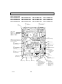
REFRIGERANT SYSTEM DIAGRAM
PMFY-P06NBMU-E
PMFY-P06NBMU-E1
PMFY-P06NBMU-E#2
PMFY-P06NBMU-ER3
PMFY-P06NBMU-ER4
PMFY-P06NBMU-ER5
PMFY-P08NBMU-E
PMFY-P08NBMU-E1
PMFY-P08NBMU-E#2
PMFY-P08NBMU-ER3
PMFY-P08NBMU-ER4
PMFY-P08NBMU-ER5
PMFY-P12NBMU-E
PMFY-P12NBMU-E1
PMFY-P12NBMU-E#2
PMFY-P12NBMU-ER3
PMFY-P12NBMU-ER4
PMFY-P12NBMU-ER5
Thermistor TH23
<Gas pipe temperature
detection>
PMFY-P15NBMU-E
PMFY-P15NBMU-E1
PMFY-P15NBMU-E#2
PMFY-P15NBMU-ER3
PMFY-P15NBMU-ER4
PMFY-P15NBMU-ER5
Strainer (#100mesh)
Gas pipe
Thermistor TH22
<Liquid pipe temperature
detection>
Flare connection
+1
+2
Liquid pipe
Heat exchanger
Strainer
(#50mesh)
Linear expansion valve
Strainer
(#100mesh)
Strainer pipe (#100mesh)
Thermistor TH21
<Room temperature detection>
Unit: in.(mm)
Service Ref.
Item
PMFY-P06/P08/P12/P15NBMU-E
PMFY-P06/P08/P12/P15NBMU-E1
PMFY-P06/P08/P12/P15NBMU-E#2
PMFY-P06/P08/P12/P15NBMU-ER3
PMFY-P06/P08/P12/P15NBMU-ER4
PMFY-P06/P08/P12/P15NBMU-ER5
Gas pipe
[1/2"(12.7)
Liquid pipe
[1/4"(6.35)
Unit: mm
Service Ref.
Item
Capillary tube W1
Capillary tube W2
OC341F
PMFY-P06/P08NBMU-E
PMFY-P06/P08NBMU-E1
PMFY-P06/P08NBMU-E#2
PMFY-P06/P08NBMU-ER3
PMFY-P06/P08NBMU-ER4
PMFY-P06/P08NBMU-ER5
PMFY-P12/P15NBMU-E
PMFY-P12/P15NBMU-E1
PMFY-P12/P15NBMU-E#2
PMFY-P12/P15NBMU-ER3
PMFY-P06/P08NBMU-ER4
PMFY-P06/P08NBMU-ER5
O.D.[4.6 × I.D.Ø3.4 ×R200 O.D.[3.6 × I.D.Ø2.4 ×R200
O.D.[3.6 × I.D.Ø2.4 ×R80
14
8
MICROPROCESSOR CONTROL
INDOOR UNIT CONTROL
8-1. COOL OPERATION
TIME SUN MON TUE WED THU FRI SAT
TIMER
Hr
ON
AFTER
AFTER OFF
ERROR CODE
FUNCTION
FILTER
ûFûC
ûFûC
WEEKLY
SIMPLE
AUTO OFF
ONLY1Hr.
TEMP.
MENU
BACK
MONITOR/SET
PAR-21MAA
ON/OFF
ON/OFF
CHECK TEST
OPERATION
CLEAR
Control modes
Control details
1-1.
Thermostat
function
1. Thermostat function
• Room temperature desired temperature + 2 °F: Thermo ON
• Room temperature desired temperature: Thermo OFF
1-2. Anti-freezing control
Detected condition: When the liquid pipe temp. (TH22) is 32˚F or less in 16
minutes from compressors start up, anti-freezing control
starts and the thermostat OFF.
Released condition: The timer which prevents reactivating is set for 3 minutes,
and anti-freezing control is cancelled when any one of the
following conditions is satisfied.
Liquid pipe temp. (TH22) turns to be 50˚F or above.
The condition of the thermostat OFF becomes
The operation mode becomes a mode other than COOL.
complete by thermostat, etc.
The operation stops.
1-3. Compressor time delay
• 3 minutes minimum off cycle.
2. Fan
OC341F
button is
FILTER
DAY
CLOCK
<How to operate>
1 Press POWER ON/OFF button.
2 Press the operation MODE button to display COOL.
3 Press the TEMP. button to set the desired temperature.
NOTE: The set temperature changes 2°F when the
or
pressed once. Cooling 67 to 87°F.
By the remote controller setting (switch of 4 speeds)
Type
Fan speed notch
4 speeds
[Low], [Medium2], [Medium1], [High]
15
Remarks
Control modes
3. Drain pump
Remarks
Control details
3-1. Drain pump control
• Always drain pump ON during the COOL and DRY mode operation.
(Regardless of the thermostat ON/OFF)
• When the operation mode is changed from COOL or DRY to any other mode
(including Stop), the drain pump continues to run for 3 minutes.
Drain sensor function
• The indoor circuit board energizes the drain sensor at a fixed voltage for a fixed
duration. After energizing, the circuit board compares the drain sensor’s
temperature to the one before energizing, and judges whether the sensor is in
+1
Drain sensor
Indoor controller
board
CN31 1
→
the air or in the water.
Basic control system
2
3
• While drain pump is turned on, it will repeat the following control system and judge
whether the sensor is in the air or in the water.
Timing of
energizing
drain sensor
ON
·······Repeat
OFF
Stand by for
a minute
30
sec.
Stand by for
a minute
Detect the
temperature
before
energizing.
(T0)
30
sec.
Detect the
temperature
after
energizing.
(T1)
Judge whether
the sensor is in
the air or in the
water.
•Drain sensor temperature rise (t)
•Temperature of drain sensor before current is applied (T0)
•Temperature of drain sensor after current is applied (T1)
[ t = T1 – T0 ]
4. Vane
→
(1) Initial setting : Start at COOL mode and horizontal vane.
(up/down vane change) (2) Vane position : Horizontal→Downward A →Downward B →Downward C→Swing
(3) Restriction of the downward vane setting
When setting the downward vane A, B or C in [Medium1], [Medium2] or [Low] of
the fan speed notch, the vane changes to horizontal position after 1 hour has
passed.
OC341F
16
+1
"Only 1 Hr"
appears on the
wired remote
controller.
8-2. DRY OPERATION
<How to operate>
1 Press POWER ON/OFF button.
2 Press the operation MODE button to display DRY.
3 Press the TEMP. button to set the desired temperature.
NOTE: The set temperature changes 2°F when the
or
pressed once. Dry 67 to 87°F.
TIME SUN MON TUE WED THU FRI SAT
TIMER
Hr
ON
AFTER
AFTER OFF
ERROR CODE
FUNCTION
FILTER
ûFûC
ûFûC
WEEKLY
SIMPLE
AUTO OFF
ONLY1Hr.
TEMP.
MENU
BACK
MONITOR/SET
PAR-21MAA
ON/OFF
ON/OFF
FILTER
DAY
CLOCK
CHECK TEST
OPERATION
CLEAR
Control modes
Remarks
Control details
1. Thermostat function 1-1. Dry mode temperature is controlled by TH21.
Dry mode ON Room temperature desired temperature + 2˚F
Dry mode OFF Room temperature desired temperature
Room
temperature
Dry mode Dry mode
ON
OFF
Room temperature (Ta) time (min) time (min)
3 min. passed since starting operation
Dry mode
ON
Over 64˚F
OFF
Ta 83˚F
9
3
83˚F > Ta 79˚F
7
3
79˚F > Ta 75˚F
5
75˚F > Ta
3
3
3
3
10
Unconditional
Less than 64˚F
Dry mode OFF
1-2. Frozen prevention control
No control function
2. Fan
Indoor fan operation control depends on the compressor conditions.
Dry mode
Fan speed notch
ON
[Low]
OFF
Stop
Note: Remote controller setting is not acceptable.
3. Drain pump
Same control as COOL operation
Same control as COOL operation
4. Vane
(up/down vane change)
OC341F
button is
17
8-3. FAN OPERATION
<How to operate>
1 Press POWER ON/OFF button.
2 Press the operation MODE button to display FAN.
TIME SUN MON TUE WED THU FRI SAT
TIMER
Hr
ON
AFTER
AFTER OFF
ERROR CODE
ûFûC
ûFûC
TEMP.
MENU
BACK
PAR-21MAA
MONITOR/SET
FUNCTION
FILTER
WEEKLY
SIMPLE
AUTO OFF
ONLY1Hr.
ON/OFF
ON/OFF
FILTER
DAY
CLOCK
CHECK TEST
OPERATION
CLEAR
Control modes
Control details
Set by remote controller.
1. Fan
2. Drain pump
Type
Fan speed notch
4 speeds type
[Low], [Medium2], [Medium1], [High]
2-1. Drain pump control
The drain pump turns ON for the specified amount of time when any of the
following conditions is satisfied:
ON for 3 minutes after the operation mode is switched from COOL or DRY to
another operation mode (FAN).
ON for 6 minutes after the drain sensor is determined to be submerged
using the liquid level detection method given below.
ON for 6 minutes after indoor piping (liquid piping) temperature – indoor
room temperature -18˚F, AND the drain sensor input is at the short or
open level.
(If condition or is still being met after the drain pump has been turned ON
for 6 minutes, the drain pump is kept ON for a further 6 minutes.)
2-2. Liquid level detection method
The liquid level is detected by determining whether or not the drain sensor is
submerged, based on the amount the temperature rises after self-heating the
sensor. This process is performed if any of the following conditions is satisfied:
Drain pump is ON.
Indoor piping (liquid piping) temperature – indoor room temperature -18˚F
Indoor piping (liquid piping) temperature or indoor room temperature is at
the short or open level temperature.
Every 1 hour after the drain pump has been switched from ON to OFF.
3. Vane
Same as the control performed during the COOL operation, but with no restriction
(up/down vane change) on the vane's downward blow setting.
OC341F
18
Remarks
8-4. HEAT OPERATION
<How to operate>
1 Press POWER ON/OFF button.
2 Press the operation MODE button to display HEAT.
3 Press the TEMP. button to set the desired temperature.
NOTE: The set temperature changes 2°F when the
or
pressed once. Heating 63 to 83°F.
TIME SUN MON TUE WED THU FRI SAT
TIMER
Hr
ON
AFTER
AFTER OFF
ERROR CODE
ûFûC
ûFûC
WEEKLY
SIMPLE
AUTO OFF
ONLY1Hr.
TEMP.
MENU
BACK
MONITOR/SET
PAR-21MAA
FUNCTION
FILTER
ON/OFF
ON/OFF
<Display in HEAT operation>
[DEFROST]
The [DEFROST] symbol is only displayed during the defrost operation.
[STANDBY]
The [STANDBY] symbol is only displayed during hot adjust mode.
FILTER
DAY
CLOCK
CHECK TEST
OPERATION
button is
CLEAR
Control modes
Remarks
Control details
1. Thermostat
function
1-1. Minimum compressor off cycle is 3 minutes.
• Room temperature desired temperature -2˚F: Thermo ON
• Room temperature desired temperature: Thermo OFF
2. Fan
Controlled by the remote controller (4-speed)
Priority is given to below-mentioned control mode
2-1. Stand by (hot adjust) mode
2-2. Preheating exclusion mode
2-3. Thermo OFF mode (When the compressor off by the thermostat)
2-4. Cool air prevention mode (Defrosting mode)
2-1. Stand by (hot adjust) mode
The fan controller becomes the stand by (hot adjust) mode for the following
conditions.
When starting the HEAT operation
When the thermostat function changes from OFF to ON.
When releasing the HEAT defrosting operation
Hot adjust mode +1
+1
"STAND BY"
will be displayed
during the stand
by (hot adjust)
mode.
Set fan speed by the remote controller
[Low]
[Extra Low]
A
B
C
A: Stand by (hot adjust) mode start
B: 5 minutes have passed since the condition A or the indoor liquid pipe
temperature turned 95°F or more
C: 2 minutes have passed since the condition A
(Terminating the stand by (hot adjust) mode)
2-2. Preheating exclusion mode
When the condition changes the auxiliary heater ON to OFF
(thermostat or operation stop, etc), the indoor fan operates in [Low] mode for
1 minute.
+1
This control is
same for the
model without
auxiliary heater.
To be continued to the next page
OC341F
19
From the preceding page
Control details
Control modes
Remarks
2-3. Thermo OFF mode
When the thermostat function changes to OFF, the indoor fan operates in
[Extra low].
2. Fan
2-4. Heat defrosting mode
The indoor fan stops.
No drain pump operation
However, when the control changes from COOL or DRY operation, the drain pump
operates for 3 minutes.
4. Vane control
(Up/down vane
change)
(1) Initial setting : OFF → HEAT···[last setting]
When changing the mode from exception of HEAT to HEAT
operation ···[Downward C]
(2) Vane position :
Horizontal →Downward A →Downward B →Downward C→Swing
→
3. Drain pump
(3) Restriction of vane position
The vane is horizontally fixed for the following modes.
(The control by the remote controller is temporarily invalidated and controlled by
the unit.)
• Thermo OFF
• Stand by (hot adjust) [Extra low] mode
• Heat defrost mode
OC341F
20
8-5. AUTO OPERATION [AUTOMATIC COOL/HEAT CHANGE OVER OPERATION]
TIME SUN MON TUE WED THU FRI SAT
TIMER
Hr
ON
AFTER
AFTER OFF
ERROR CODE
ûFûC
ûFûC
TEMP.
MENU
BACK
MONITOR/SET
PAR-21MAA
FUNCTION
FILTER
WEEKLY
SIMPLE
AUTO OFF
ONLY1Hr.
ON/OFF
ON/OFF
FILTER
DAY
CLOCK
CHECK TEST
OPERATION
<How to operate>
1 Press POWER ON/OFF button.
2 Press the operation MODE button to display AUTO.
3 Press the TEMP. button to set the desired temperature.
NOTE: The set temperature changes 2°F when the
or
button is
pressed once. Automatic 67 to 83°F.
When in AUTO mode, the unit will switch from either heat or cool
automatically to maintain the set temperature.
CLEAR
Control details
Control modes
Remarks
1. Initial value of HEAT mode for room temperature < Desired temperature
operation mode COOL mode for room temperature Desired temperature
2. Mode change (1) HEAT mode → COOL mode
Room temperature Desired temperature + 3˚F or 3 minutes has passed
(2) COOL mode → HEAT mode
Room temperature Desired temperature - 3˚F or 3 minutes has passed
3. COOL mode
Same control as cool operation
4. HEAT mode
Same control as heat operation
8-6. WHEN UNIT IS STOPPED
Control modes
1. Drain pump
Control details
1-1. Drain pump control
The drain pump turns ON for the specified amount of time when any of the
following conditions is satisfied.
(regardless of whether the compressor is ON or OFF)
ON for 3 minutes after the operation mode is switched from COOL or DRY to
another operation mode (HEAT mode).
ON for 6 minutes after the drain sensor is determined to be submerged using the
liquid level detection method given below.
ON for 6 minutes after indoor piping (liquid piping) temperature – indoor room
temperature 14˚F, and the drain sensor input is at the short or open level.
(If condition or is still being met after the drain pump has been turned ON for 6
minutes, the drain pump is kept ON for a further 6 minutes.)
1-2. Liquid level detection method
The liquid level is detected by determining whether or not the drain sensor is
submerged, based on the amount the temperature rises after self-heating the
sensor.
This process is performed if any of the following conditions is satisfied:
Drain pump is ON.
Indoor piping (liquid piping) temperature – indoor room temperature 14˚F
(except during defrosting)
Indoor piping (liquid piping) temperature or indoor room temperature is at the
short or open level temperature.
Every 1 hour after the drain pump has been switched from ON to OFF.
OC341F
21
Remarks
9
TROUBLESHOOTING
9-1. HOW TO CHECK THE PARTS
PMFY-P06NBMU-E
PMFY-P06NBMU-E1
PMFY-P06NBMU-E#2
PMFY-P06NBMU-ER3
PMFY-P06NBMU-ER4
PMFY-P06NBMU-ER5
PMFY-P08NBMU-E
PMFY-P08NBMU-E1
PMFY-P08NBMU-E#2
PMFY-P08NBMU-ER3
PMFY-P08NBMU-ER4
PMFY-P08NBMU-ER5
PMFY-P12NBMU-E
PMFY-P12NBMU-E1
PMFY-P12NBMU-E#2
PMFY-P12NBMU-ER3
PMFY-P12NBMU-ER4
PMFY-P12NBMU-ER5
Parts name
PMFY-P15NBMU-E
PMFY-P15NBMU-E1
PMFY-P15NBMU-E#2
PMFY-P15NBMU-ER3
PMFY-P15NBMU-ER4
PMFY-P15NBMU-ER5
Check points
Thermistor (TH21)
<Room temperature
detection>
Thermistor (TH22)
<Liquid pipe temperature
detection>
Disconnect the connector then measure the resistance with a tester.
(At the ambient temperature 50˚F~86˚F)
Normal
Abnormal
4.3k ~ 9.6k
Open or short
Refer to the next page for the details.
Thermistor (TH23)
<Gas pipe temperature
detection>
Vane motor (MV)
Yellow Connector
MV
Brown — Red
Green Orange
Linear expansion
valve (LEV)
Abnormal
Brown — Orange
380 $ 7%
Open or short
Brown — Green
Disconnect the connector then measure the resistance with a tester.
Blue
Normal
Brown — Yellow
Red Brown M
Measure the resistance between the terminals with a tester.
(At the ambient temperature 68˚F~86˚F)
Brown
Normal
White-Red
Abnormal
Yellow-Brown Orange-Red
Yellow
Blue-Brown
200 $ 10%
Open or short
Refer to the next
page for the details.
Orange
Red
White
Drain pump (DP)
Blue
Blue
Measure the resistance between the terminals with a tester.
(At the ambient temperature 68˚F)
1
Normal
Abnormal
3
400~480
Open or short
Drain sensor (DS)
1
2
3
OC341F
Measure the resistance after 3 minutes have passed since the power supply was turned off.
(At the ambient temperature 32˚F~140˚F
Normal
Abnormal
0.6k~6.0k
Open or short
22
Refer to the next page for the details.
< Thermistor for lower temperature >
<Thermistor characteristic graph>
50
Thermistor for
Thermistor <Room temperature detection> (TH21)
lower temperature
Thermistor <Liquid pipe temperature detection> (TH22)
Thermistor <Gas pipe temperature detection> (TH23)
Resistance (k)
40
Thermistor R0=15k' ± 3%
Fixed number of B=3480 ± 2%
1
1
Rt=15exp { 3480(
)}
273+(t-32)/1.8
273
30_F 15.8k'
50_F
9.6k'
70_F
6.0k'
80_F
4.8k'
90_F
3.9k'
100_F
3.2k'
Thermistor for
Drain sensor (DS)
drain sensor
30_F
50_F
70_F
80_F
0
-20
0
20
40
60
80
100
120
Temperature (˚F)
10
< Thermistor for drain sensor >
9
Resistance (k)
8
1
1 )}
273+(t-32)/1.8
273
90_F
1.6k'
100_F 1.3k'
140_F 0.6k'
6.3k'
3.9k'
2.5k'
2.0k'
20
10
Thermistor R0=6.0k' ±5%
Fixed number of B=3390 ±2%
Rt=6exp { 3390(
30
7
6
5
4
3
2
1
0
20
40
60
80
100
120
140 170
Temperature (°F)
Linear expansion valve
1 Operation summary of the linear expansion valve
• Linear expansion valves open/close through the use of a stepping motor after receiving the pulse signal from the indoor
controller board.
• Valve position can be changed in proportion to the number of pulse signals.
<Connection between the indoor controller board and the linear expansion valve>
Controller board
DC12V
Linear expansion valve
4
M
6
5
2
1
White Red
3
Orange
Blue
Brown
6
Red
5
Drive circuit
Brown
:4
Blue
4
:4
Yellow
:3
Orange
3
:3
:2
Yellow
2
:2
:1
White
1
:1
Connector (CN60)
Note : Since the number of the connector at the controller board side and the relay connector are different, follow the color of
the lead wire.
OC341F
23
<Output pulse signal and the valve operation>
Output
Output
(Phase)
1
2
3
4
{1
ON
OFF
OFF
ON
{2
ON
ON
OFF
OFF
{3
OFF
ON
ON
OFF
{4
OFF
OFF
ON
ON
2 Linear expansion valve operation
C
D
Closing a valve : 1 → 2 → 3 → 4 → 1
Opening a valve : 4 → 3 → 2 → 1 → 4
The output pulse shifts in above order.
• When linear expansion valve operation stops, all output phase
become OFF.
• At phase interruption or when phase does not shift in order, motor
does not rotate smoothly and motor will lock and vibrate.
• When the switch is turned on, 2200 pulse closing valve signal will be
sent till it goes to point A in order to define the valve position.
Valve position (capacity)
• When the valve moves smoothly, there is no sound or vibration
occurring from the linear expansion valves : however, when the
pulse number moves from E to A or when the valve is locked, more
sound can be heard than in a normal situation.
Close
Open
2000 pulse
Opening a valve
all the way
A
E
• Sound can be detected by placing the ear against the screw driver
handle while putting the screw driver tip to the linear expansion
valve.
Pulse number
B
Extra tightening (80~100pulse)
3 Troubleshooting
Symptom
Check points
Countermeasures
Operation circuit
failure of the micro
processor
Disconnect the connector on the controller board, then connect LED for checking.
6
5
4
3
2
1
1k LED
When power is turned on, pulse signals will send for 10
seconds. If the LED does not light or keeps lighting even
after the signals stop, that means some failures in the
operation circuit.
Exchange the indoor controller board at drive circuit
failure.
Linear expansion
valve mechanism is
locked.
Motor will idle and make a ticking noise when the motor is
Exchange the linear expanoperated while the linear expansion valve is locked. This tick- sion valve.
ing sound is the sign of the abnormality.
Short or breakage
Measure the resistance between each coil (white-red, yellow- Exchange the linear expanof the motor coil of
brown, orange-red, blue-brown) with a tester. It is normal if
sion valve.
the linear expansion the resistance is in the range of 200" ±10%.
valve
Valve does not close To check the linear expansion valve, operate the indoor unit If large amount of refrigercompletely.
in fan mode and at the same time operate other indoor units ant is leaked, exchange
the linear expansion valve.
in cooling mode, then check the pipe temperature <liquid
pipe temperature> of the indoor unit by the
outdoor multi controller board operation
monitor. During fan operation, linear expansion valve is closed completely and if there
Thermistor
(Liquid pipe) is any leaking, detecting temperature of
the thermistor will go lower. If the detected
Linear
expansion
temperature is much lower than the temvalve
perature indicated in the remote controller,
it means the valve is not closed all the way.
It is not necessary to exchange the linear expansion valve, if
the leakage is small and not affecting normal operation.
Wrong connection
of the connector or
contact failure
OC341F
Check the color of lead wire and missing terminal of the con- Disconnect the connector
nector.
at the controller board,
then check the continuity.
24
9-2. FAN MOTOR CHECK
Check method of indoor fan motor (fan motor/controller board)
Notes
· High voltage is applied to the connecter (FAN)(CNMF1, 2) for the fan motor. Pay attention to the service.
· Do not pull out the connector (FAN)(CNMF1, 2) for the motor with the power supply on, doing so may result in damage
to the board.
(FAN)
PMFY-P06/08/12/15NBMU-E
PMFY-P06/08/12/15NBMU-E1
(CNMF1, 2)
PMFY-P06/08/12/15NBMU-E#2
PMFY-P06/08/12/15NBMU-ER3
PMFY-P06/08/12/15NBMU-ER4 PMFY-P06/08/12/15NBMU-ER5
Self check
Symptom : The indoor fan can not rotate.
Indoor controller board fuse check
Is the fuse normal?
Is the resistance
between the terminals of
drain pump normal?
No
Yes
Replace the fan motor.
Replace the indoor controller board.
No
Wiring contact check
Contact of fan motor connector (FAN) (CNMF1,2)
Is there contact failure?
Yes
Replace the drain pump.
Yes
Wiring recovery
No
Turn ON the power supply.
Power supply check
Check the voltage of the indoor controller board with the connector (FAN) (CNMF1, 2)connected to the board.
Approx. 294~325V DC between the connecter < (FAN) (+) and (–) > < (CNMF1)
(+) and (CNMF2)
(-) >
Yes
Is the voltage normal?
Replace
the fan motor.
No
OK
Check the operation
NG
Replace the the indoor controler board.
Replace the indoor controller board.
OK
Check the operation
END
NG
Replace the fan motor.
OC341F
25
END
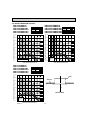
9-3. FUNCTION OF DIP SWITCH
Switch Pole
SW1
Function
setting
Operation by switch
Function
ON
1
Thermistor <Room temperature
detection> position
Built-in remote controller
Indoor unit
2
Filter clogging detection
Provided
Not provided
3
Filter cleaning sign
2,500h
100h
4
Fresh air intake
Switching remote
controller display
Effective
Thermo ON
signal display
Not effective
Indicating fan operation
ON/OFF
5
Effective
timing
Remarks
Address board
<Initial setting>
ON
OFF
1 2 3 4 5 6 7 8 9 10
Under
suspension
6
Humidifier control
Fan operation at Heating mode
Thermo ON operation at
Heating mode
7
Air flow at
Low +
Extra low +
8
OFF
OFF
Extra low
Heat thermo OFF
Setting air flow
Depends on SW1-7
ON
OFF
Low
9
Auto restart function
Effective
Not effective
OFF
ON
Setting air flow
ON
ON
Stop
Effective
Not effective
10
Power ON/OFF by breaker
MODELS
SW2
Capacity
1~6
code
setting
SW3
Function
setting
OFF
SW 2
ON
PMFY-P06NBMU-E OFF
SW 1-7 SW 1-8
1 2 3 4 5 6
PMFY-P12NBMU-E OFF
1 2 3 4 5 6
ON
1 2 3 4 5 6
Indoor controller board
SW 2
ON
ON
PMFY-P08NBMU-E OFF
MODELS
+
PMFY-P15NBMU-E OFF
Before
power
supply
ON
<Initial setting>
Set for each capacity.
1 2 3 4 5 6
1
Heat pump/Cool only
Cooling only
Heat pump
2
Louver
Available
Not available
3
Vane
Available
Not available
Indoor controller board
4
Vane swing function
Available
Not available
5
Vane horizontal angle
Second setting +6
First setting
6
Vane cooling limit angle setting +4 Horizontal angle
Down B, C
7
Changing the opening of linear
expansion valve when the
thermostat is OFF
Effective
Not effective
8
Heating 4deg. up
Not effective
Effective
9
Target superheat setting +5
—
—
10
Target sub cool setting +5
—
—
<Initial setting>
ON
OFF
1 2 3 4 5 6 7 8 9 10
( +4 ) At cooling mode, each
angle can be used only
1 hour.
Under
( +5 ) SW 3-9 setting
suspension PMFY-P06, P08NBMU-E=ON
PMFY-P12, P15NBMU-E=OFF
SW 3-10 setting
PMFY-P06, P08NBMU-E=ON
PMFY-P12, P15NBMU-E=OFF
Do not use SW3-9, 10 as trouble
might be caused by the usage
condition.
+6 Second setting
means first setting.
In case replacing the indoor controller board, make sure to set the switch to the
SW4
initial setting, which is shown below.
Model
Selection
PMFY-P·NBMU-E
PMFY-P·NBMU-E1
(Setting 1~5
ON
ON
for
PMFY
OFF
OFF
series)
1 2 3 4 5
1 2 3 4 5
OC341F
Before
PMFY-P·NBMU-E#2/ER3/ER4/ER5 power
ON
supply
OFF
ON
1 2 3 4 5
26
Indoor controller board
Switch Pole
Effective
timing
Remarks
SW11
90 1
90 1
78
SW12
23
45 6
45 6
1
<Initial setting>
23
10
How to set addresses
Example : If address is “3”, remain SW12
(for over 10) at “0”, and match SW11 (for 1 to 9)
with “3”.
78
78
78
90 1
45 6
SW11
90 1
45 6
SW12
23
Rotary switch
Address board
23
SW11
1s digit
address
setting
SW12
10ths digit
address
setting
Operation by switch
<Initial setting>
SW14
F01
45 6
Before
power
supply
ON
23
How to set branch numbers SW14 (Series R2 only)
Match the indoor unit’s refrigerant pipe with
the BC controller’s end connection number.
Remain other than series R2 at “0”.
CDE
AB
45 6
CDE
AB
F01
789
SW14
23
789
SW14
Branch
No.
setting
Rotary switch
Address board
Address board
SW5
Voltage
Selection
220V
(208V)
2
OC341F
240V
(230V) If the unit is used at the 230V area, set the voltage
to 230V.
If the unit is used at the 208V, set the voltage
to 208V.
27
<Initial setting>
220V
240V
(208V)
(230V)
9-4. TEST POINT DIAGRAM
9-4-1. Indoor controller board
PMFY-P06NBMU-E
PMFY-P06NBMU-E1
PMFY-P08NBMU-E
PMFY-P08NBMU-E1
SW2
Capacity setting
PMFY-P12NBMU-E
PMFY-P12NBMU-E1
SW3
Function setting
CN32
Connector
(Remote switch)
PMFY-P15NBMU-E
PMFY-P15NBMU-E1
SW4
Model selection
CN27
Connector
(Damper)
12VDC (1 : +)
CN6V
Vane motor output
(MV)
12VDC pulse output
CNP
Drain pump output
(DP)
Between 1 to 3
208-230V AC
CN52
Remote indicator
1-2: Status lamp 12VDC (1 : +)
Fan motor output (SW1-5 OFF)
Thermostat ON (SW1-5 ON)
1-3: Cooling/Dry status lamp
12VDC (1 : +)
1-4: Heating status lamp
12VDC (1 : +)
CND
Connect to the
terminal block (TB2)
(Power supply for
indoor controller
board connecting
wire)
Between 1 to 3
208-230V AC
CN51
Centrally control
1-2 : Control signal
12VDC pulse input
(1 : +)
3-4 : Operation indicator
12VDC (3 : +)
3-5 : Malfunction indicator
12VDC (3 : +)
FUSE
6A 250V
FAN
Fan motor output
(MF)
CN41
HA terminal-A
CN60
Linear expansion
valve output (LEV)
12VDC pulse output
CN20
Room temperature
thermistor (TH21)
CN21
Pipe temperature
thermistor/Liquid
(TH22)
CN29
Pipe temperature
thermistor/Gas
(TH23)
CN31
Drain sensor (DS)
OC341F
LED1
Power supply (I.B)
(Indoor unit :
208-230V)
LED2
Power supply (R.B)
CN3A
Connect to the terminal block (TB15)
(MA-Remote controller connecting wire)
Between 1 to 3 8.7-13V DC (Pin1 (+))
28
CN2M
Connect to the terminal block (TB5)
(M-NET transmission connecting wire)
24-30V DC (non-polar)
Indoor controller board
PMFY-P06NBMU-E#2
PMFY-P06NBMU-ER3
PMFY-P06NBMU-ER4
PMFY-P06NBMU-ER5
PMFY-P08NBMU-E#2
PMFY-P08NBMU-ER3
PMFY-P08NBMU-ER4
PMFY-P08NBMU-ER5
FUSE
6.3A 250V
PMFY-P12NBMU-E#2
PMFY-P12NBMU-ER3
PMFY-P12NBMU-ER4
PMFY-P12NBMU-ER5
CND
Power supply
1-2 : 208-230V AC
PMFY-P15NBMU-E#2
PMFY-P15NBMU-ER3
PMFY-P15NBMU-ER4
PMFY-P15NBMU-ER5
CNP
Drain pump output (DP)
1-3 : 208-230V AC
CNMF1, CNMF2
FAN motor
CNMF11-CNMF21 : 294-325V DC
CNMF23-1 : 15V DC
CNMF25-1 : 0-6.5V DC
CNMF27-1 : 0-15V DC
LED1
Main power supply
CN2M
Connect to the terminal block TB5
(M-NET transmission connecting wire)
24-30V DC (non-polar)
CN31
Drain sensor (DS)
LED2
Power supply for
MA-Remote controller
CN60
Linear expansion valve
(LEV)
12VDC pulse output
CN20
Room thermistor/Liquid
(TH21)
CN3A
MA-Remote controller
connecting wire
1-3 8.7-13V DC (Pin 1 (+))
CN44
Pipe temperature
1-2: thermistor/Liquid
(TH22)
3-4: thermistor/Gas
(TH23)
CN6V1
Vane motor
12VDC pulse output
CN27
Damper
12VDC (1 : +)
CN32
Connector
(Remote switch)
CN24
External heater
12VDC (1 : +)
*except PMFY-P•NBMU-E#2
SW2
Capacity setting
OC341F
SW3
Function setting
SW4
Model setting
29
CN52
Remote indicator
1-2: Status lamp 12VDC (1 : +)
Fan motor output (SW1-5 OFF)
Thermostat ON (SW1-5 ON)
1-3: Cooling/Dry status lamp
12VDC (1 : +)
1-4: Heating status lamp
12VDC (1 : +)
CN51
Centrally control
1-2 : Control signal
12VDC pulse input
(1 : +)
3-4 : Operation indicator
12VDC (3 : +)
3-5 : Malfunction indicator
12VDC (3 : +)
9-4-2. Address board
PMFY-P06NBMU-E
PMFY-P06NBMU-E1
PMFY-P06NBMU-E#2
PMFY-P06NBMU-ER3
PMFY-P06NBMU-ER4
PMFY-P06NBMU-ER5
PMFY-P08NBMU-E
PMFY-P08NBMU-E1
PMFY-P08NBMU-E#2
PMFY-P08NBMU-ER3
PMFY-P08NBMU-ER4
PMFY-P08NBMU-ER5
SW1
Function setting
SW12
Address setting
10ths DIGIT
OC341F
PMFY-P12NBMU-E
PMFY-P12NBMU-E1
PMFY-P12NBMU-E#2
PMFY-P12NBMU-ER3
PMFY-P12NBMU-ER4
PMFY-P12NBMU-ER5
PMFY-P15NBMU-E
PMFY-P15NBMU-E1
PMFY-P15NBMU-E#2
PMFY-P15NBMU-ER3
PMFY-P15NBMU-ER4
PMFY-P15NBMU-ER5
SW5
Voltage selector
SW11
Address setting
1s DIGIT
30
SW14
Branch No.
10
DISASSEMBLY PROCEDURE
PMFY-P06NBMU-E
PMFY-P06NBMU-E1
PMFY-P06NBMU-E#2
PMFY-P06NBMU-ER3
PMFY-P06NBMU-ER4
PMFY-P06NBMU-ER5
PMFY-P08NBMU-E
PMFY-P08NBMU-E1
PMFY-P08NBMU-E#2
PMFY-P08NBMU-ER3
PMFY-P08NBMU-ER4
PMFY-P08NBMU-ER5
PMFY-P12NBMU-E
PMFY-P12NBMU-E1
PMFY-P12NBMU-E#2
PMFY-P12NBMU-ER3
PMFY-P12NBMU-ER4
PMFY-P12NBMU-ER5
PMFY-P15NBMU-E
PMFY-P15NBMU-E1
PMFY-P15NBMU-E#2
PMFY-P15NBMU-ER3
PMFY-P15NBMU-ER4
PMFY-P15NBMU-ER5
Be careful when removing heavy parts.
OPERATING PROCEDURE
PHOTOS & ILLUSTRATIONS
Air intake grille
Photo 1
1. Removing the grille
Opening the air intake grille
(1) Press the PUSH of the air intake grille. (See Figure 1)
(2) Put your fingers on the both ends of nut of the air intake
grille and put it down after the grille clicked.
Air outlet
grille
Nozzle
Removing the air intake grille
(1) Press the PUSH of the air intake grille, and pull down the
both ends of nut with your fingers after the grille clicked.
(See Figure 1)
(2) Pull out the handle of air intake grille strongly toward you.
(See Figure 2)
(3) Draw the string of the air intake grille to prevent the air
intake grille from dropping. (See Figure 3)
Air filter
Figure 1
PUSH
Checks before setting the grille in place
(1) Before installing the grille, make sure the indoor unit is
square with the ceiling opening (or parallel to the angle
between the wall and the ceiling).
(2) Check that the 4 points where the grille will be secured are
in contact with the ceiling surface.
(3) Check that the insulation for the refrigerant pipes, drainage pipes, etc. is in place and that wiring connections and
arrangements are complete.
Figure 4
Figure 2
Points for securing the grille
Points for securing the grille
Figure 3
Figure 5
Points for securing
the grille
Ceiling surface
OC341F
Drainage
pan
Make sure these
surfaces are flush with
each other (0-3 mm).
31
String for dropping
prevention
OPERATING PROCEDURE
PHOTOS & ILLUSTRATIONS
Figure 6
Removing the grille
Hooks
(1) Open the intake grille by pressing PUSH of the air intake
grille and remove the air filter (× 2). (See Figure 1)
(2) Remove the screw cover in the middle of the air outlet. (See
Figure 7)
(3) Open the upper and lower flaps on the indoor unit completely. (See Figure 7)
(4) Remove the securing screws (× 7).
(A: M5 × 0.8 × 16, 6pcs)
(B: 4 × 16, 1pc)
(5) Remove the temporary holding tabs on the grille to the
hooks on the indoor unit.
Temporary holding tabs
A
A
B
A A
A
A
Attaching the grille
(1) Open the upper and lower flaps on the indoor unit completely.
(2) Hook the temporary holding tabs on the front panel to the
hooks on the indoor unit.
(3) Adjust the grille so that it fits properly in the angle between
the ceiling and the wall, and install the securing screws A
(supplied with this grille) in their 4 places at left and right,
leaving them slightly loose.
(4) Tighten the securing bolts A and securing screws B in the
centre 3 places. (See Figure 6)
(5) Tighten the securing bolts A in the 4 places at left and right.
* Make sure there are no gaps between the indoor unit and
the grille, and between the grille and the ceiling surface.
If there are gaps, the wind may come in and it may cause
water to drip. (See Figure 8)
* Tighten the securing bolts A and securing screws B completely.
(6) Replace the air filter and screw cover, and press PUSH of
the intake grille until you hear it snap into place.
Figure 7
Hooks
Upper and lower flaps
* Open completely
Temporary
holding tabs
Temporary
holding tabs
Screw cover
Figure 8
Checks after setting the grille
(1) Check that there are no gaps between the indoor unit and
the grille, between the grille and the ceiling surface. If there
are gaps, the wind may come in and condensation may
result.
(2) Check that the air filter is in place.
Indoor unit
Ceiling surface
OC341F
32
No gaps between the
indoor unit and the grille
Grille
OPERATING PROCEDURE
PHOTOS & ILLUSTRATIONS
2. Removing the electrical parts box
(1) Remove the panel.
(2) Remove the address board cover.
(3) Remove the electrical parts cover.
(4) Disconnect the connectors of
fan motor, vane motor,
drain pump, room temperature thermistor,
pipe temperature thermistor (Liquid. Gas),
condenser/evaporator temperature thermistor,
and drain sensor on the electrical controller board.
(5) Disconnect the lead wire and earth wire from terminal
block.
(6) Remove the electrical parts box.
Photo 2
Claw in middle
of nozzle
Nozzle
Electrical parts
Drain pan
Photo 3
Electrical parts
cover
Address board
cover
Photo 4
3. Removing the nozzle
Note when the nozzle is removed.
Nozzle
Heat exchanger
· The insulation material (white) which prevents water
drop is mounted to the side of vane motor. Remove the
insulation material before removing nozzle.
(See Figure 4)
· After completing the service, re-mount the insulation
material as before as shown in right figure.
· After service, mount the double layer insulation without
fail.
The hard material side should be faced toward the nozzle.
(See Figure 4)
Vane motor
Room temperature thermistor
(1) Remove the panel.
(2) Remove the room temperature thermistor.
(3) Unhook the claws in the middle of nozzle and remove the
drain pan. (5 screws) (See Photo 2)
(4) Remove the nozzle side of the heat exchanger. (2 screws)
(5) Remove the address board cover. (See Photo 3)
(6) Remove the electrical parts cover. (See Photo 3)
(7) Disconnect the connector of vane motor.
(8) Remove the insulation material (white) on the right side of
nozzle.
(9) Remove the nozzle. (6 screws)
Insulation material
Hard side of insulation
Nozzle
Vane motor
Photo 5
4. Removing the vane motor
(1) Remove the nozzle. Refer to above-mentioned
3. Removing the nozzle.
(2) Remove the vane motor from the nozzle.
OC341F
Figure 9
Vane motor
33
Soft side of insulation
OPERATING PROCEDURE
PHOTOS & ILLUSTRATIONS
5. Removing the drain pump
(1) Remove the panel.
(2) Unhook the claw in the middle of nozzle and remove the
drain pan. (See Photo 2)
(3) Remove the address board cover. (See Photo 3)
(4) Remove the electrical parts cover. (See Photo 3)
(5) Disconnect the connector of drain pump.
(6) Remove the drain hose.
(7) Remove the drain pump. (2 screws)
Photo 6
Drain sensor
Drain pump
Fan motor
6. Removing the fan motor and line flow fan
(1) Remove the panel.
(2) Unhook the claw in the middle of nozzle and remove the
drain pan. (See Photo 2)
(3) Unscrew 2 screws at the nozzle side of the heat exchanger.
(4) Remove the address board cover. (See Photo 3)
(5) Remove the electrical parts cover. (See Photo 3)
(6) Disconnect the connector of vane motor, fan motor and
drain pump.
(7) Remove the nozzle side of the heat exchanger. (2 screws)
(8) Remove the nozzle.
(9) Remove the drain pump.
(10) Unscrew 2 screws in the motor support.
(11) Remove the fan motor and line flow fan. (The fan motor
and line flow fan can be removed without removing the
heat exchanger.)
7. Removing the thermistor <Room temperature detection>
(1) Remove the panel.
(2) Remove the address board cover.
(3) Remove the electrical parts cover.
(4) Remove the thermistor. <Intake temperature detector>
(5) Disconnect the lead wire from the cord clamp. (5 points)
(6) Disconnect the connector (CN20) on the indoor controller
board.
8. Removing the thermistor
<Liquid pipe temperature detection>
<Gas pipe temperature detection>
(1) Remove the panel.
(2) Remove the address board cover.
(3) Remove the electrical parts cover.
(4) Remove the drain pan.
(5) Remove the thermistor <Gas pipe temperature detection>/
<Liquid pipe temperature detection>.
(6) Disconnect the lead wire from the cord clamp.
(7) Disconnect the connector (CN21)/(CN29), (CN44) on the
indoor controller board.
Connector (CN21) / Liquid (NBMU(1))
(CN29) / Gas (NBMU(1))
(CN44) / Liquid and Gas (NBMU#2, NBMUR3,
NBMUR4, NBMUR5)
OC341F
34
Photo 7
Fan motor
Line flow fan
11
RoHS PARTS LIST
PANEL PARTS
PMP-16BMU (FOR PMFY-P06/08/12/15NBMU-E • PMFY-P06/08/12/15NBMU-E1)
PMP-16BMUW (FOR PMFY-P06/08/12/15NBMU-E#2 • PMFY-P06/08/12/15NBMU-ER3 •
PMFY-P06/08/12/15NBMU-ER4 • PMFY-P06/08/12/15NBMU-ER5)
11
2
10
10
1
3
4
2
3
9
4
5
8
6
7
RoHS
Q'ty/set
Part No.
G
T7W E16 003
AIR OUTLET GRILLE
G
T7W E22 003
AIR OUTLET GRILLE
2
G
R01 E01 055
LATCH
2
2
3
G
R01 E01 099
PANEL HOOK
2
2
4
G
R01 E07 054
GRILLE CATCH
2
2
5
G
R01 E14 500
L.L.FILTER
1
1
6
G
R01 E15 500
L.L.FILTER
1
1
G
T7W E04 691
INTAKE GRILLE
1
G
T7W E06 691
INTAKE GRILLE
8
G
R01 E06 054
GRILLE SHAFT
2
2
9
G
R01 E01 648
RECEIVER COVER
1
1
2
No.
1
7
Part Name
Specification
PMP-16
BMU
BMUW
1
1
1
10 G
R01 E01 044
MAGNET
2
G
R01 E04 096
SCREW CAP
1
G
R01 E07 096
SCREW CAP
11
OC341F
1
35
Wiring RecomRemarks
mended
(Drawing No.) Diagram
Symbol
Q'ty
RoHS PARTS LIST
FUNCTIONAL PARTS
PMFY-P06NBMU-E
PMFY-P08NBMU-E
PMFY-P12NBMU-E
PMFY-P15NBMU-E
PMFY-P06NBMU-E1
PMFY-P08NBMU-E1
PMFY-P12NBMU-E1
PMFY-P15NBMU-E1
23
22
21
17
20
1
19
2
16
3
15
4
5
14
6
13
7
12
11
8
10
9
OC341F
36
18
RoHS PARTS LIST
No.
1
2
3
4
5
6
7
8
9
10
11
12
13
14
15
16
17
18
19
20
21
22
23
RoHS
Part number that is circled is not shown in the figure.
G
G
G
G
G
G
G
G
G
G
G
G
G
G
G
G
G
G
G
G
G
G
G
G
G
Part No.
R01
R01
R01
R01
R01
R01
T7W
T7W
R01
R01
R01
R01
R01
R01
R01
R01
R01
R01
T7W
R01
R01
R01
R01
R01
R01
OC341F
23A
E04
E32
E01
E18
E02
H08
H09
E30
H12
E03
H16
H17
H06
E16
E05
32K
E11
E11
E35
E24
E45
E13
E05
E03
Part Name
102
103
114
079
223
092
480
480
529
202
038
202
202
401
002
110
241
266
355
130
220
220
105
527
673
BEARING MOUNT
SLEEVE BEARING
LINE FLOW FAN
STABILIZER ASSY
VANE MOTOR
VANE SLEEVE
HEAT EXCHANGER
HEAT EXCHANGER
DRAIN PAN ASSY
THERMISTOR
GUIDE VANE
THERMISTOR
THERMISTOR
EXPANSION VALVE
VANE
CASING ASSY
SENSOR HOLDER
DRAIN SENSOR
DRAIN PUMP
MOTOR SUPPORT
FAN MOTOR
FAN MOTOR
MOTOR MOUNT
DRAIN PIPE ASSY
SCREW & WASHER
Q'ty/set
Wiring RecomPMFYRemarks
Diagram mended
Specification
(Drawing
No.)
P·NBMU-E P·NBMU-E1
Symbol
Q'ty
06/08 12/15 06/08 12/15
1
1
1
1
1
1
1
ROOM
LIQUID
GAS
1
1
1
1
1
1
1
1
1
1
1
1
1
1
1
1
37
1
1
1
1
1
1
1
1
1
1
1
1
1
1
1
1
1
1
1
1
1
1
1
1
1
1
1
1
1
1
1
1
1
1
1
1
1
1
1
1
1
1
1
1
1
1
1
1
1
1
1
1
1
1
1
1
1
1
1
1
1
1
1
1
1
1
1
1
1
MV
TH21
8pcs/set
TH22
TH23
LEV
DS
DP
MF
MF
set
RoHS PARTS LIST
FUNCTIONAL PARTS
PMFY-P06NBMU-E#2
PMFY-P08NBMU-E#2
PMFY-P12NBMU-E#2
PMFY-P15NBMU-E#2
PMFY-P06NBMU-ER3
PMFY-P08NBMU-ER3
PMFY-P12NBMU-ER3
PMFY-P15NBMU-ER3
PMFY-P06NBMU-ER4
PMFY-P08NBMU-ER4
PMFY-P12NBMU-ER4
PMFY-P15NBMU-ER4
PMFY-P06NBMU-ER5
PMFY-P08NBMU-ER5
PMFY-P12NBMU-ER5
PMFY-P15NBMU-ER5
23
22
21
16
20
19
1
18
2
15
3
14
4
5
13
6
12
7
11
8
10
9
OC341F
38
17
RoHS PARTS LIST
Part number that is circled is not shown in the figure.
Q'ty/set
RoHS
PMFY-P·
Wiring RecomRemarks
NBMU-E#2
NBMU-ER4 (Drawing No.) Diagram mended
Symbol
Q'ty
NBMU-ER3
NBMU-ER5
06/08 12/15 06/08 12/15
No.
Part No.
1
G
R01 23A 102
BEARING MOUNT
1
1
1
1
2
G
R01 E04 103
SLEEVING BEARING
1
1
1
1
Part Name
Specification
3
G
R01 E32 114
LINE FLOW FAN
1
1
1
1
4
G
R01 E01 079
STABILIZER ASSY
1
1
1
1
5
G
R01 E18 223
VANE MOTOR
1
1
1
1
6
G
R01 E02 092
VANE SLEEVE
1
1
1
1
G
T7W H92 480
HEAT EXCHANGER
1
G
T7W H93 480
HEAT EXCHANGER
8
G
R01 E30 529
DRAIN PAN ASSY
9
G
R01 H12 202
THERMISTOR
10 G
R01 E03 038
GUIDE VANE
11 G
R01 N15 202
THERMISTOR
12 G
R01 H06 401
13 G
14 G
7
MV
1
1
1
1
1
1
1
1
1
1
1
1
1
1
1
1
1
1
1
TH22,23
EXPANSION VALVE
1
1
1
1
LEV
R01 E16 002
VANE
1
1
1
1
R01 E05 110
CASING ASSY
1
1
1
1
15 G
R01 32K 241
SENSOR HOLDER
1
1
1
1
16 G
R01 E11 266
DRAIN SENSOR
1
1
1
1
DS
DP
ROOM
LIQUID/GAS
17 G
T7W E11 355
DRAIN PUMP
1
1
1
1
18 G
R01 E35 130
MOTOR SUPPORT
1
1
1
1
19 G
R01 E49 220
FAN MOTOR
1
1
1
1
20 G
R01 E13 105
MOTOR MOUNT
1
1
1
1
G
R01 E05 527
DRAIN PIPE ASSY
1
1
G
R01 E10 527
DRAIN PIPE ASSY
1
1
22 G
R01 18J 523
JOINT SOCKET
23 G
R01 E03 673
SCREW & WASHER
21
OC341F
1
39
1
1
1
1
1
TH21
8pcs/set
MF
L/R set
set
RoHS PARTS LIST
ELECTRICAL PARTS
PMFY-P06NBMU-E
PMFY-P06NBMU-E1
PMFY-P06NBMU-E#2
PMFY-P06NBMU-ER3
PMFY-P06NBMU-ER4
PMFY-P06NBMU-ER5
PMFY-P08NBMU-E
PMFY-P08NBMU-E1
PMFY-P08NBMU-E#2
PMFY-P08NBMU-ER3
PMFY-P08NBMU-ER4
PMFY-P08NBMU-ER5
PMFY-P12NBMU-E
PMFY-P12NBMU-E1
PMFY-P12NBMU-E#2
PMFY-P12NBMU-ER3
PMFY-P12NBMU-ER4
PMFY-P12NBMU-ER5
PMFY-P15NBMU-E
PMFY-P15NBMU-E1
PMFY-P15NBMU-E#2
PMFY-P15NBMU-ER3
PMFY-P15NBMU-ER4
PMFY-P15NBMU-ER5
RG79L094H01
7
CN60
FAN
1
6
2
CN6V
CNP
3
5
No.
RoHS
4
Part No.
Part No.
1 G T7W E41 716 TERMINAL BLOCK
Q'ty/set
Remarks Wiring RecomPMFY-P06/08/12/15
Specification
(Drawing Diagram mended
NBMU- NBMU- NBMU- NBMU- NBMU- NBMU- No.) Symbol Q'ty
E
E1
E#2
ER3
ER4
ER5
3P (L1, L2, GR)
1
1
1
1
1
1
TB2
2 G R01 E27 246 TERMINAL BLOCK
3P (M1, M2, S)
1
1
1
1
1
1
TB5
3 G R01 E53 246 TERMINAL BLOCK
2P (1, 2)
1
1
1
1
1
1
TB15
A.B
4 G T7W E01 294 ADDRESS BOARD
1
1
1
1
1
1
5 G R01 E10 304 CABLE ASSY
1
1
1
1
1
1
1
1
1
1
1
1
6
G T7W 420 239 FUSE
250V, 6A
G R01 E06 239 FUSE
250V, 6.3A
G T7W E59 310 INDOOR CONTROLLER BOARD
1
G T7W E67 310 INDOOR CONTROLLER BOARD
I.B
1
7 G T7W E72 310 INDOOR CONTROLLER BOARD
I.B
1
G T7W E85 310 INDOOR CONTROLLER BOARD
I.B
1
G T7W C04 310 INDOOR CONTROLLER BOARD
OC341F
FUSE
1
I.B
1
40
FUSE
I.B
OC341F
41
TM
HEAD OFFICE : TOKYO BLDG., 2-7-3, MARUNOUCHI, CHIYODA-KU, TOKYO100-8310, JAPAN
cCopyright 2005 MITSUBISHI ELECTRIC CORPORATION
Distributed in Apr. 2012 No. OC341 REVISED EDITION-F
Distributed in Dec. 2009 No. OC341 REVISED EDITION-E PDF 7
Distributed in Dec. 2008 No. OC341 REVISED EDITION-D PDF 7
Distributed in May 2008 No. OC341 REVISED EDITION-C PDF 7
Distributed in Jul. 2007 No. OC341 REVISED EDITION-B PDF 9
Distributed in Aug. 2006 No. OC341 REVISED EDITION-A PDF 9
Distributed in Jun. 2005 No. OC341 PDF 10
Made in Japan
New publication, effective Apr. 2012
Specifications are subject to change without notice.