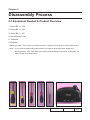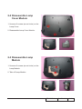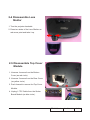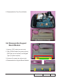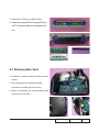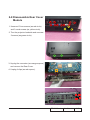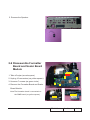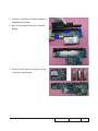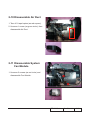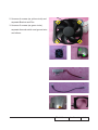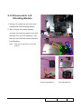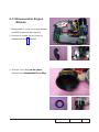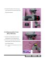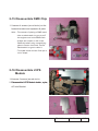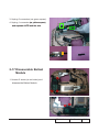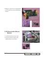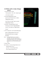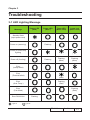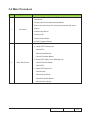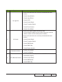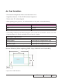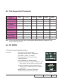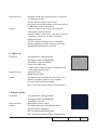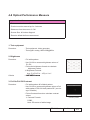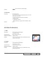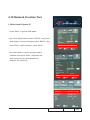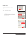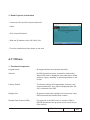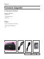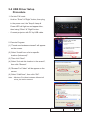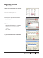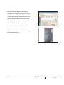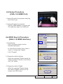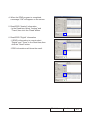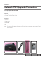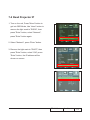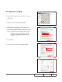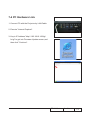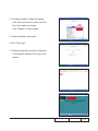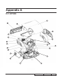
1
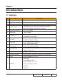
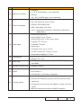
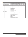
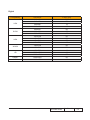
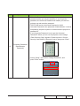
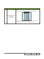
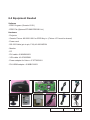
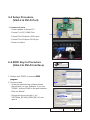
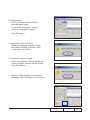
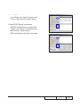
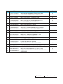
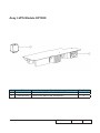
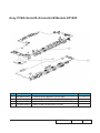
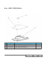
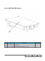
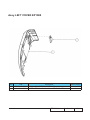
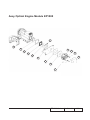
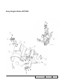
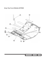
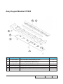
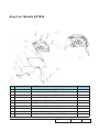
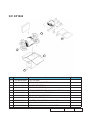
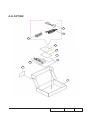
SERVICE MANUAL
EP1080/DX1080/OP1990/VE810/DP7290/
PV8530/P350/TX1080
Date
Revise Version
Description
2008.09.10
V1.0
Initial Issue
2008.09.22
V2.0
Modify Chapter 1 and add Chapter 7
2009.03.13
V3.0
Add EP1080 extended models: DX1080, OP1990,
VE810, DP7290, PV8530, P350, TX1080 and amend
the method of getting into FW mode in Chapter 5
Copyright March, 2009. All Rights Reserved P/N:36.8BH03G001
SI :
TSE:
Check:
Approved:
Preface
This manual is applied to EP1080 Series projection system. The manual gives you a brief
description of basic technical information to help in service and maintain the product.
Your customers will appreciate the quick response time when you immediately identify
problems that occur with our products. We expect your customers will appreciate the
service that you offer them.
This manual is for technicians and people who have an electronic background. Please
send the product back to the distributor for repairing and do not attempt to do anything that
is complex or is not mentioned in the troubleshooting.
Notice: The information found in this manual is subject to change without prior notice. Any subsequent changes made to the data herein will be incorporated in future edition.
EP1080 Series Service Manual
Copyright March.2009
All Rights Reserved
Manual Version 3.0
EP1080 Series
Confidential
I
Table of Content
Chapter 1
Introduction
Highlight
1-1
Compatible Mode
1-4
Chapter 2 Disassembly Process
Equipment Needed & Product Overview
2-1
Disassemble Lamp Cover Module
2-2
Disassemble Lamp Module
2-2
Disassemble Lens Shelter
2-3
Disassemble Top Cover Module
2-3
Disassemble Keypad Board Module
2-4
Disassemble Vent
2-5
Disassemble Rear Cover Module
2-7
Disassemble Formatter Board and Scaler Board Module
2-8
Disassemble Air Ductor
2-10
Disassemble System Fan Module
2-10
Disassemble Left Shielding Module
2-12
Disassemble Engine Module
2-13
Disassemble Color Wheel Module
2-14
Disassemble DMD Chip
2-15
Disassemble LVPS Module
2-15
Disassemble Ballast Module
2-16
Disassemble Blower Module
2-17
Disassemble Safety Switch
2-18
Disassemble IR Sensor Board and AIR Duct
2-18
EP1080 Series
Confidential
II
Disassemble Left and Right Elevator Module
2-19
Rod Adjustment
2-21
Re-write Lamp Usage Hour
2-22
Chapter 3 Troubleshooting
LED Lighting Message
3-1
Main Procedure
3-2
Chapter 4 Function Test & Alignment Procedure
Test Equipment Needed
4-1
Service Mode
4-1
OSD Reset
4-1
Test Condition
4-2
Test Inspection Procedure
4-3
PC MODE
4-3
Calibration
4-7
Optical Performance Measure
4-10
Video Performance
4-12
Network Function Test
4-14
Others
4-16
Chapter 5 Firmware Upgrade
Equipment Needed
5-1
USB Driver Setup Procedure
5-2
Firmware Upgrade Procedure
5-3
EP1080 Series
Confidential
III
Chapter 6 EDID Upgrade
EDID Introduction
6-1
Equipment Needed
6-2
Setup Procedure(VGA-2 & DVI-D Port)
6-3
EDID Key-In Procedure(VGA-2 & DVI-D Interface)
6-3
Setup Procedure(VGA-1 & HDMI Port)
6-6
EDID Key-In Procedure(VGA-1 & HDMI Interface)
6-6
Chapter 7 Network FW Upgrade
Equipment Needed
7-1
Read Projector IP
7-2
Network Setting
7-3
PC Hardware Link
7-4
Appendix A Exploded Image
I
Appendix B
Serial Number System Definition XIX
PCBA Code Definition
XX EP1080 Series
Confidential
IV
Chapter 1
Introduction
1-1 Highlight
No
Item
Description
1
Dimension (L x W x H)
• 411 x 311 x 116 (mm)
2
Weight
• Unit(projector): approx. 10 lbs (< 11lb)
3
Tilt Angle
• 6 degree with elevator mechanism
4
Power Supply
5
Keystone correction
• -5°~ +10° Vertical
6
Resolution
• 1920 x 1080P
7
Brightness
8
Contrast
9
Uniformity
10
Throw ratio
11
Projection lens
12
Color wheel
• 5 Segment, RYGWB (R80Y40G82W78B80)
13
System controller
• Dual DDP3021, DAD1000, PMD1000 for 1080p DMD
14
Lamp
• Philips 300Watt E21.9 UHP
• Universal AC 100--240V; 50 / 60 Hz with PFC input
• Provide for Philips 300W UHP E21.9 lamp
• 2,872 ANSI Lumens (Typical)
• 2,584 ANSI Lumens (Min.)
• 1,500 :1 full on/full off (Typical)
• 1,200 :1 full on/full off (Min.)
• 70% Japan standard (Typical)
• 60% Japan Standard (Min.)
• 1.85 – 2.22:1 distance/width
• F/ 2.6~2.89, f = 39.12~46.91 mm. 1.2X Zoomed Focal Lens.
• Offset : 136 +/- 5%
• Operating
0~2,500 ft 5°C~35°C
15
Altitude
2,500~5,000 ft 5°C~30°C
5,000~10,000 ft 5°C~25°C
• Storage
40,000 ft
EP1080 Series
Confidential
1-
No
Item
Description
• Operating:
16
Maximum Humidity
5 ~ 35°C, 80%RH (Max.), non-condensing
• Storage:
-20 ~ 60°C, 80%RH (Max.), non-condensing
• NTSC: NTSC M/J, NTSC 4.43
• PAL: PAL B/D/I/G/H, PAL M, PAL N
17
Video compatibility
• SECAM: SECAM B/D/G/K/L
• SDTV: 480i, 480p, 576i, 576p,
• HDTV: 720p(50Hz),720p(60Hz),1080i(50Hz),1080i(60Hz),
1080p (60Hz)����������
• Analog RGB signal(PC)
Analog RGB 0.7Vp-p, 75 ohm
Analog RGB 1Vp-p, 75 ohm, Sync. signal
Separate TTL H,V Sync.
18
Input signal
Composite TTL Sync.
• Video signal
Composite video 1Vp-p, 75 ohm
S-video Luminance 0.714Vp-p, 75 ohm
Chrominance 0.286Vp-p, 75 ohm
19
Temperature
20
DMD Chip
21
Number of active dots
• Operating: 5 ~ 35°C
• Storage: -20 ~ 60°C
• TI DMD, Single chip 0.95” Dark Chip 1 LVDS 1080p Super
value DMD
• 1920(H) x 1080(V)
• in (3.5mm) x 3 for VGA1, VGA2, DVI-D
22
Audio
• out (3.5mm) x 1
• in RCA(L/R) x 1 for S-video, Composite
• Advanced air flow
• One fan/ two blowers(in projector) with low system acoustic
23
Cooling System
noise level
• Temperature control circuits with adaptive voltage control fan
speed
• Max touch temperature follows UL60950 regulation
EP1080 Series
Confidential
1- No
Item
Description
• Full power(at normal mode):typical 400W+/-10% at 110V AC
24
Power consumption
• ECO power(at ECO mode):typical 340W +/-10% at 110V AC
• Standby mode: < 14W at 110V AC
• One HDMI input connectors (Support Audio input)
• One DVI-D input
• Two VGA input
• One VGA output
• One S-Video
• One Composite Video
25
Terminal
• One 12V relay
• Audio-in (3.5mm) x 3 for VGA1, VGA2, DVI-D
• Audio-out (3.5mm) x 1
• Audio-in RCA(L/R) x 1 for S-video, Composite
• One D-sub 9-pin RS-232 port
• USB x 1 (Type B)
• RJ-45 x 1
• One 3-pin AC power inlet port
EP1080 Series
Confidential
1-
1-2 Compatible Mode
Analog
Compatibility
Resolution
V-Sync [Hz]
640x350
70
640x350
85
640x400
85
640x480
640x480
640x480
60
72
75
640x480
85
720x400
70
720x400
85
800x600
56
800x600
60
800x600
72
800x600
75
800x600
85
1024x768
60
1024x768
70
1024x768
75
1024x768
85
1280x720
60
1280x768
60
1280x768
85
1280x1024
60
1280x1024
75
SXGA+
1400x1050
60
UXGA
1600x1200
60
VGA
SVGA
XGA
WXGA*
SXGA
EP1080 Series
Confidential
1-4
Digital
Compatibility
VGA
SVGA
XGA
WXGA
HD
SXGA+
UXGA
Resolution
640x480
V-Sync [Hz]
60
640x480
72
640x480
75
640x480
85
800x600
800x600
800x600
1024x768
1024x768
1024x768
1024x768
1280x768
60
75
85
60
70
75
85
60
1280x768
70
1280x720
1280x1024
1280x1024
1400x1050
1600x1200
60
60
75
60
60
EP1080 Series
Confidential
1-
Chapter 2
Disassembly Process
2-1 Equipment Needed & Product Overview
1. Screw Bit (+) :105
2. Screw Bit (+) :107
3. Screw Bit (-) :107
4. Hex Sleeves 5 mm
5. Tweezers
6. Projector
* Before you start: This process is protective level II. Operators should wear electrostatic chains.
* Note: - If you need to replace the scaler board, you have to record the lamp usage hour.
- As the process of EP1080 extended models disassembling is the same as EP1080, we take EP1080 for example here.
EP1080 Series
Confidential
2-
2-2 Disassemble Lamp
Cover Module
1. Unscrew 2 screws (as red circle) on the
Lamp Cover.
2. Disassemble Lamp Cover Module.
2-3 Disassemble Lamp
Module
1. Unscrew 2 screws (as red circle) on the
Lamp Module.
2. Take off Lamp Module.
EP1080 Series
Confidential
2-
2-4 Disassemble Lens
Shelter
1. Turn the projector backside.
2. Press two sides of the Lens Shelter as
red arrow point and take it up.
2-5 Disassemble Top Cover
Module
1. Unscrew 4 screws from the Bottom
Cover (as red circle).
2. Unscrew 2 screws from the Rear Cover
(as yellow circle).
3. Push forward to remove the Top Cover
Module.
4. Unplug 1 FPC Cable from the Scaler
Board Module (as blue circle).
EP1080 Series
Confidential
2-
5. Disassemble the Top Cover Module.
2-6 Disassemble Keypad
Board Module
1. Unplug 1 FPC cable (as red circle).
2. Take off EMI Gasket (as green square),
EMI Type (as red square) and Keypad
Type (as yellow square).
3. Unscrew 5 screws (as yellow circle).
4. Disassemble the Keypad Board Module.
EP1080 Series
Confidential
2-
5. Unscrew 5 screws (as blue circle).
6. Separate Keypad Board,Keypad Button,
LED Transparent Bar and Keypad Bracket.
2-7 Disassemble Vent
1. Unscrew 1 screw on the Left Vent (as red
circle).
2. Turn the projector to backside and
unscrew 3 screws (as blue circle).
3. Uplug 1 connector (as yellow square) and
remove the Left Vent.
EP1080 Series
Confidential
2-
4. Unplug 4 clips (as red sqaure) and
remove the Speaker.
5. Unscrew 2 screws on the Right Vent
(as green circle).
6. Turn the projector backside and unscrew
3 screws (as orange circle).
7. Remove the Right Vent.
EP1080 Series
Confidential
2-
2-8 Disassemble Rear Cover
Module
1. Unscrew 10 hex screws (as red circle)
and 3 usual screws (as yellow circle).
2. Turn the projector backside and unscrew
3 screws (as green circle).
3. Unplug the connector (as orange sqaure)
and remove the Rear Cover.
4. Unplug 4 clips (as red sqaure).
EP1080 Series
Confidential
2-
5. Remove the Speaker.
2-9 Disassemble Formatter
Board and Scaler Board
Module
1. Take off mylar (as red square).
2. Unplug 10 connectors (as yellow square).
3. Unscrew 7 screws (as green circle).
4. Remove the Formatter Board and Scaler
Board Module.
Note:The formatter board is connected on
the DMD board (as yellow square).
EP1080 Series
Confidential
2-
5. Unplug 3 connectors (as blue square) to
seperate two boards.
6. Take off Lan Board from the Formatter
Board.
7. Take off 3 Hex screws (as green circle)
from the Scaler Board.
EP1080 Series
Confidential
2-
2-10 Disassemble Air Duct
1. Tear off 1 tape kapton (as red square).
2. Unscrew 1 screw (as green circle), then
disassemble Air Duct.
2-11 Disassemble System
Fan Module
1. Unscrew 2 screws (as red circle) and
disassemble Fan Module.
EP1080 Series
Confidential
2-10
2. Unscrew 4 screws (as yellow circle) and
separate Bracket and Fan.
3. Unscrew 2 screws (as green circle),
separate thermal switch and ground wire
and others.
EP1080 Series
Confidential
2-11
2-12 Disassemble Left
Shielding Module
1. Unscrew 3 screws (as red circle) and
disassemble Left Shielding Module.
2.Tear off mylar (as orange square),
unscrew 3 screws (as green circle) and
separate Fan and Left Shielding , then
tear off mylar (as blue square) from the
Left Shielding.
Note: - Take the Fan Module as the right gesture.
the wrong gesture
EP1080 Series
the right gesture
Confidential
2-12
2-13 Disassemble Engine
Module
1. Disassemble 1 mylar (as orange square)
and EMI Gasket (as blue square).
2 .Unscrew 6 screws (as red circle) to
disassemble Engine Module.
3. Turn the Focus Ring���������������
as the yellow
direction,then �����������������������
disassemble Focus Ring.
EP1080 Series
Confidential
2-13
4. Unscrew 2 screws on the zoom ring
cover (as red circle),remove the Zoom
Ring as the picture.
2-14 Disassemble Color
Wheel Module
1. Unscrew 2 screws (as red circle) to
disassemble Color Wheel Module.
2. Unscrew 1 screw (as yellow circle) to
disassemble Photo Sensor Board from
Color Wheel Module.
Note: - Avoid to touch the glass parts of color
wheel.
EP1080 Series
Confidential
2-14
2-15 Disassemble DMD Chip
1. Unscrew 4 screws (as red circle) on the
heatsink bracket and separate all parts.
Note: - T
he manner of placing a DMD mask.
-U
se an electrostatic ion gun to puff
the engine room in the DMD mask.
- If there are scrapes or dirt on the
DMD chip when using a magnifying
glass to have a close look, use an
electrostatic ion gun to clean it.
-T
o double check and see if the pin is
out of shape.
2-16 Disassemble LVPS Module
1.Unscrew 6 screws (as red circle).
2. Disassemble
���������������������������������������
LVPS Module holder, mylar,
AC Inlet Bracket.
EP1080 Series
Confidential
2-15
3. Unplug 2 connectors (as green square).
4. Unplug 1 connector �������������������
(as yellow square)
and
��������������������������������
separate LVPS and the wire .
2-17 Disassemble Ballast
Module
1. Unsrew 5 srews (as red circle),and
disassemble Ballast Module.
EP1080 Series
Confidential
2-16
2. Unplug 3 connectors (as orange square)
and all wires,then dissassemble Ballast
Module.
2-18 Disassemble Blower
Module
1. Unscrew 2 screws (as red circle).
2. Remove the Blower Module and
separate Blower and Rubber.
EP1080 Series
Confidential
2-17
2-19 Disassemble Safety
Switch
1.Unscrew 3 screws (as red cirle).
2. Disassemble Safety Switch.
2-20 Disassemble IR Sensor Board and AIR Duct
1. Tear off 1 mylar (as yellow square) and
EMI Gasket (as green square).
2. Take off IR Sensor Board.
EP1080 Series
Confidential
2-18
3. Unscrew 2 screws (as red circle).
4. Take off AIR Duct.
2-21 Disassemble Left and Right Elevator Module
1. Unscrew 3 screws on the Left Elevator
Module (as red circle).
EP1080 Series
Confidential
2-19
2. Hold the Elevator and press the push
button (as orange square).
3. When pressing the push button,the
elevator foot will get loose and be easily
to be pulled down to separate the
Elevator Module.
4. The methed of disassembling the Right
Elevator Module is the same as the Left
Elevator Module.
EP1080 Series
Confidential
2-20
2-22 Rod Adjustment
1. Environment Adjustment
- The distance between the engine and
the screen is 2.45M.
- This process should be done at a dark
environment(under 5 Lux).
2. Procedure Adjustment
- Change
the screen to “white screen.”
- Adjust the screws by using the rod on
the engine module to readjust the image.
(“screw 1“ should be asjusted first, and
then “screw 2“. Adjust until the yellowish
2
1
or bluish parts disappeared.)
3. Abnormal image inspection
- It should not have any abnormal color
at the rim of the image by estimating
through the eyes.
Note: - To avoid over adjusting the rod.
- After the opreation, please use the glue
to fix the screws.
EP1080 Series
Confidential
2-21
2-23 Re-write Lamp Usage
Hour
1. Get into service mode
-P
ress (power→left→left→down) to get
into service mode 2.
2. Re-write Bright Mode Hours
- Use "up" and "down" key to select
"Bright Mode Hours".
- Use "left" and "right" key to re-write
"Bright Mode Hours".
3. Re-write "Standard Mode Hours"
- The way of re-write "Standard Mode
Hours" is the same as "Bright Mode
Hours".
4. The "Lamp Hour" will increase/decrease
follow the Bright Mode Hours and
Standard Mode Hours increase/
decrease.
Note: - The Bright Mode Hours increase/ decrease 1 hour,the lamp Hour will increase/decrease 1 hour.The Standard Mode Hours increase/decrease 2 hours, the lamp Hour will increase/decrease 1 hour.
5. Chose "Exit".
Note: left key = decrease Bright Mode Hours/
Standard Mode Hours,
right key = increase Bright Mode
Hours/ Standard Mode Hours.
EP1080 Series
Confidential
2-22
Chapter 3
Troubleshooting
3-1 LED Lighting Message
Power LED
(Red)
Message
Power LED
(Blue )
Temp LED
(Blue / Red)
Lamp Led
(Blue / Red)
(Blue)
(Blue)
Flashing
(Blue)
Flashing
(Blue)
Standby State
(input power cord)
Power on (warming)
Flashing
Power on and Lamp
fighting
Power off (Cooling)
Flashing
Error
(Lamp failed)
(Red)
Error
(Thermal failed)
(Red)
Error
(Over Temp.)
Flashing
(Red)
Error
(Fan failed)
Flashing
(Red)
Error RS232 fail
Light on
Flashing
Light off
EP1080 Series
Confidential
3-
3-2 Main Procedure
No
Symptom
Procedure
- Ensure the Power Cord and AC Power Outlet are securely
connected
- Check Lamp Cover and Interrupt Switch
- Ensure all connectors are securely connected and aren’t
1
No Power
broken
- Check Lamp Driver
- Check LVPS
- Check Scaler Board
- Check Formatter Board
- Check LED Status
a. Lamp LED Flashing red
- Check Fan
- Check Scalar Board
- Check Formatter Board
b. Temp LED Lights red or Flashing red
2
Auto Shut Down
- Check Thermal Switch
- Check Fan
c. Lamp LED Lights red
- Check Lamp
- Check Lamp Driver
- Check Formatter Board
- Check Photo Sensor
EP1080 Series
Confidential
3-
No
Symptom
Procedure
- Ensure all connectors are securely connected and aren’t
broken
- Check Lamp Module
- Check Lamp Driver
3
No Light On
- Check LVPS
- Check Scaler Board
- Check Formatter Board
- Check Photo Sensor
- Check Color Wheel
- Ensure the Signal Cable and Source work
(If you connect multiple sources at the same time, use the
“Source” button on the control panel to switch)
- Ensure all connectors are securely connected and aren’t
broken
4
No Image
- Check Scaler Board
- Check Formatter Board
- Check DMD Board
- Check DMD Chip
- Check Engine Module
5
Mechanical Noise
- Check Color Wheel
- Check Fan Module
- Check if the Formatter Board and the DMD Board are
assembled properly
6
Line Bar/Line Defect
- Check Scaler Board
- Check DMD Board
- Check DMD Chip
EP1080 Series
Confidential
3-
No
Symptom
Procedure
- Do “Reset (All data)” of the OSD Menu
- Ensure that the signal cables and source are work as well
- Check Lamp Module
7
Image Flicker
- Check Color Wheel
- Check DMD Board
- Check Scaler Board
- Check Formatter Board
- Do “Reset (All data)” of the OSD Menu
- Adjust Color Wheel Index
8
Color Abnormal
- Check Scaler Board
- Check Formatter Board
- Check DMD Board
- Check Color Wheel
- Ensure the projection screen without dirt
- Ensure the projection lens is clean
9
Poor Uniformity/
Shadow
- Ensure the Brightness is within spec
- Check rod alignment
- Check Engine Module
- Ensure the projection screen without dirt
- Ensure the projection lens is clean
10
Dead Pixel/Dust
(Out of spec.)
- Clean DMD Chip and Engine Module
- Check DMD Chip
- Check Engine Module
- Ensure that the signal cables and source work as well.
11
Garbage Image
- Check Scaler Board
- Check Formatter Board
- Check DMD Board
EP1080 Series
Confidential
3-
No
Symptom
Procedure
- Remote Control
a. Check Battery
b. Check Remote Controller
c. IR receiver
12
Remote Control/
Control Panel Failed
d. Check Scaler Board
e. Check Formatter Board
- Control Panel
a. Check FPC
b. Check Keypad
c. Check Scaler Board
- Do “Reset (All data)” of the OSD Menu
13
Function Abnormal
- Check Scaler Board
- Check Formatter Board
- Check DMD Board
- Ensure that the signal cables and source are work as well
14
Audio Abnormal
- Check Speaker Module
- Check Scaler Board
- Check Formatter Board
15
Network Function
Abnormal
- Ensure RJ45 Connector work as well (Normal Status: Before
joining RJ45 line, Orange LED flashing, after joining RJ45
line, and Internet transmission speed over 100MB/second,
Green LED will light.)
- Check Internet Source and Network Module if LED message is
in abnormal status.
- Check Formatter Board if LED message is in normal status.
EP1080 Series
Confidential
3-
No
Symptom
Procedure
- When the Password Protect is on, you must enter the
password before you use the projector. If you forget the
password, the Universal Password will enable you start the
projector up and reset the password.
- The EP1080 series’s Universal Password is 2468.
- Universal Password is the password of Administrator. It can be
accepted by projector anytime no matter what the projector’s
password is.
- If you forget the Password, how to get the Universal
Password? When you turn on the projector, the message
“Enter Security Code” appears. Please Input the “Current
Security Code 2468” by Remote Control, then press “Enter”.
16
Forgetting Password
(administrator
Password)
- Select “Setup”, then select “Change Password”, and
press” Enter” button.
EP1080 Series
Confidential
3-
No
Symptom
Procedure
- The message “Enter New Security Code” appears. Input a
4-digits code (letters and/or numbers) that you define.
Forgetting Password
(administrator
Password)
- To confirm, enter the password again. The “Security Code
change successfully” appear on the screen.
EP1080 Series
Confidential
3-
Chapter 4
Function Test & Alignment Procedure
4-1 Test Equipment Needed
- IBM PC with HOME resolution
- Equipped “Component”, “S-Video” , “Composite” ,"DVI-D", "VGA", "SCART" and "HDMI."
- HDTV Source (480P,576P,720P,1080i,1080P)
- Minolta CL-100
- Quantum Data 802B or CHROMA2327 (Color Video Signal & Pattern Generator)
- After changing parts, check the information below.
4-2 Service Mode
1. Turn on the projector and input the signal
2. Do the following actions sequentially to get into service mode 1
- Press "Power", "Left", "Left" and "Up" buttons continuous.
3.Do the following actions sequentially to get into service mode 2
- Press "Power", "Left", "Left" and "Down" buttons continuous.
4-3 OSD Reset
1. After final QC step, we have to erase all saved change again and resotre the OSD
default setting. The following actions will allow you to erase all end-users' settings and
restore the default setting:
(1) Please get into OSD menu.
(2) To execute "Reset" function.
EP1080 Series
Confidential
4-1
4-4 Test Condition
- Circumstance brightness: Dark room less than 5.0 lux.
- Inspection distance: 1.8 M~2.5 M functional inspection.
- Screen size: 60 inches diagonal
- After repairing each projector, the unit should be run-in (refer to the table below)
Symptom
Normal repair
NFF
Auto shutdown
Run-in Time
2 hours
4 hours
6 hours
- Get into Burn-In Mode
* Cycle setting is based on the defect symptoms. ie: If it is NFF, the run-in time is 4 hours. You have
to set the lamp on for 50 min. and lamp off for 10 min for 4 cycles.
Press power > left > left > up
Choose Burn-In Test > enter
Lamp On (Min)
Press right key to adjust the time (50)
Lamp Off (Min)
Press right key to adjust the time (10)
Set burn in cycle
Press right key to adjust the cycle
After setting up the time, choose Burn-In mode and hit enter
Screen Defects (While replacing DMD Chip, DMD BD and Scaler BD)
< Figure: Zone A &B Definition >
EP1080
Confidential
4-2
4-5 Test Inspection Procedure
Scaler/
Board
Firmware
Version Update
v
v
Color Wheel Index
v
PC
Calibration
v
v
Video
Calibration
v
v
Change parts
Update
Color
Wheel
Lamp
Module
Engine
Module
Rod
Module
v
v
v
Reset lamp hour
v
OSD Reset
v
EDID
v
Re-write Lamp
Hour Usage
v
v
Rod Adjustment
Note: If Color appears abnormal after changing Main Board Module, please do Color Wheel index adjustment.
4-6 PC MODE
1. Frequency and tracking boundary
Procedure
- Test equipment: video generator.
- Test signal: analog 1280 x 1024@60Hz
- Test Pattern: general-1 or master
- Check and see if the image sharpness
is well-performed.
- If not re-adjust by the following steps:
(1) S
elect "Frequency" function to adjust the total
pixel number of pixel clock in one line period.
General-1
(2) S
elect "Tracking" function and use right or
left arrow key to adjust the value to minimize
video flicker.
- Adjust Resync or Frequency/Tracking/H.
Position/V. Position to the inner screen.
EP1080 Series
Master
Confidential
4-3
Inspection item
- Eliminate visual wavy noise by Rsync, Frequency
or Tracking selection.
- Check if there is noise on the screen.
- Horizontal and vertical position of the video should
be adjustable to the screen frame.
Criteria
- If there is noise on the screen, the product is
considered as failure product.
- If there is noise on the screen, use auto or manual
“frequency” function or “tracking” function to
adjust the screen.
- The PC mode functionally sure be workable
include support format with frequency and auto
detected functional will be workable.
2. Light Leak
Procedure - Test equipment: video generator.
- Test signal: analog 1080p@60Hz - Test Pattern: gray 10 patterns
- Check if the light leaks.
* Light leak on reflective edge, eyecatcher, bond
wires and exposed metal.
Inspection item
- Light leak check.
- Bright blemish (dirty).
Criteria
- The pattern cannot accept the color level of the
leakage is brighter than the gray 10 pattern.
- Ref. the Defect specification table
Gray 10
Note: The defect criteria follows TI specification.
3. Blemish (Dark)
Procedure - Test equipment: video generator.
- Test signal: analog 1080p@60Hz - Test Pattern: blue 60
Inspection item
- Dark blemish check. (dirty)
Criteria
- The bright blemish is unacceptable when it
appears on blue 60 pattern.
Blue 60
- Ref. the Defect specification table
Note: The defect criteria follows TI specification.
EP1080 Series
Confidential
4-4
4. Dead Pixel (Bright pixel)
Procedure - Test equipment: video generator.
- Test signal: analog 1280x720@60Hz.
- Test Pattern: full black
Inspection item
- Bright pixel check.
Note: Frame dimension under operative zone 1
inch
Criteria
- Bright pixel is unacceptable.
- Ref. the Defect specification table
Full black
Note: The defect criteria follows TI specification.
5. Dead Pixel (Dark pixel)
Procedure - Test equipment: video generator.
- Test signal: analog 1280x720@60Hz.
- Test Pattern: full white
Inspection item
- Dead pixel check.
- White pattern (IRE=100)
- Adjacent dark pixel.
Criteria
- The number of the dead pixels should be less or
equal to 6 pixels.
- Adjacent pixel with each other is unacceptable.
- Ref. the Defect specification table
Full white
Note: The defect criteria follows TI specification.
6. Focus test
Procedure - Test equipment: video generator.
- Test signal: analog 1024 x768@75Hz
- Test Pattern: full screen or MEME Sony
Inspection item
- Focus check
Criteria
-From screen 2.5 M via visual to check the focus,
look at the entire screen, focus shall be clear,
crisp, and sharp over the entire surface of the
display pattern. (Blur word on one of the corner
after adjustment is acceptable. However, the
word should at least be recognizable.)
Full screen
MEME Sony
EP1080 Series
Confidential
4-5
7. Color performance
Procedure - Test equipment: video generator.
- Test signal: DVI 480p,1080i
- Test Pattern: Master, In focus II or SMPTE
RP-133
* Please refer to 4-2 to get into service mode. Use
480p &1080i signal, master pattern to do HDTV
test. Color cannot discolor to purple and blue.
Inspection item
- Check if each color level is well-functioned.
- Color saturation
Criteria
- Screen appears normal. It should not have any
abnormal condition, such as lines appear on the
screen and so on.
- Color appears normal.
- It is acceptable to have few lines flashing at the
center and on the edge of 1080i image. However,
rest of the image should appears stable.
- RGBW should all appear normal on the screen
and sort from R -G-B-W.
- Color levels should be sufficient and normal. (the
unidentified color levels on both left and right
sides should not over 8 color levels.)
- Gray level should not have abnormal color or
heavy lines.
- The PC mode functionally sure be workable
include support format with frequency and auto
detected functional will be workable
Master
InFocus II
/ 64 gray RGBW
SMPTE RP-133
4-7 Calibration
1. Video calibration
Procedure - Test equipment: video generator.
- Once scalar board is changed, Video calibration
should be done as well.
(1) Test signal: 720P
EP1080 Series
Confidential
4-6
(2) Test Pattern: SMPTE BAR
- Note
(1) Calibration pattern should be in fill screen
mode.
(2) Please refer to 4-2 to get into Service Mode
and OSD Reset.
SMPTE BAR
(3) Choose and access Video Calibration for correction in service mode. Choose “menu” to
leave the service mode after all.
*Note: Video adjustment can only be used once.If
there is any circumstances which needs to be
re-adjust ,the adjustment is only effective when
you adjust at the odd number of times. Otherwise,
the black will not be dark enough.
Check pattern
- Test signal: 720P
- Test pattern: In focus SMPTE BAR.
Inspection item
- Color saturation
Criteria
- There should not have any lack of SMPTE BAR.
The color should appear normal and sort in right
order.
- Color levels should be sufficient and normal. (the
unidentified color levels on both left and right sides
should not over 8 color levels.)
- Gray level should not have abnormal color or
heavy lines.
2. PC calibration
Procedure
- Test equipment: video generator
- Once scaler board is changed, PC calibration
should be done as well.
(1) Test signal analog: 800x600@60Hz (2) Test Pattern: gray 16 (800x600@60Hz)
- Note
(1) Calibration pattern should be in fill screen
mode.
Gray 16
(2) Please refer to 4-2 to get into Service Mode
and OSD Reset.
EP1080 Series
Confidential
4-7
(3) Choose and access PC Calibration for
correction in service mode. Choose
“menu” to leave the service mode after
all.
Check pattern
- Test signal: analog 800 x 600@60Hz
- Test pattern: In focus II or 64 gray RGBW
* After finishing ADC adjustment, check 64
gray RGBW pattern, adjust CW index in
color setting of service mode.
Inspection item
- Color saturation
Criteria
- There should not have any lack of RGBW.
The color should appear normal and sort in
right order.
- Color levels should be sufficient and normal.
(the unidentified color levels on both left and
right sides should not over 8 color levels.)
- Gray level should not have abnormal color
or heavy lines.
In focus II / 64 gray
RGBW
Defect specification table
Order
Symptom
Pattern
Black pattern
Criteria
1
Bright pixel ( dots)
2
Dark pixel(dots)
White pattern
A+B=6
3
Unstable pixel (dots)
Any pattern
A+B=1
4
Adjacent dark pixel (dots)
Any pattern
A+B=0
5
Dark blemish (Dirty)
Blue 60 pattern
6
Bright blemish (Dirty)
Gray 10 pattern
7
Bright dot on frame
Black pattern
( IRE=O)
A+B=0
A+B=2
(diameter <1/2 inch)
A+B=2
(diameter <1/2 inch)
2
EP1080 Series
Confidential
4-8
4-8 Optical Performance Measure
Inspection Condition
- Environment luminance: 5 Lux
- Product must be warmed up for 3 minutes
- Distances from the screen: 2.5 M
- Screen Size: 60 inches diagonal
- Reset to default before measurement
1. Test equipment
Procedure - Test equipment: video generator.
- Test signal: analog 1920x1080@60Hz.
2. Brightness
Procedure - Full white pattern
- Use CL100 to measure brightness values of P1~P9.
- Follow the brightness formula to calculate
brightness values.
☼ Brightness Formula
Criteria
Avg. (P1+P2+P3+...+P9) x1.1 m²
Full white pattern
��•�����������������
����������������
1400 ANSI Lumens
3. Full On/Full Off Contrast
Procedure
- Full white pattern & full black pattern
- Use CL100 to measure brightness values of full
white pattern P5 & full black pattern B5 ( see image: full white)
- Follow Contrast formula to calculate contrast
values.
☼ Contrast Formula
P5/B5
Note: P
5=center of white image
Full black pattern
EP1080 Series
Confidential
4-9
Criteria
B5 = the center of black image.
��•�������
������
1200:1
4. Uniformity
Procedure
- Full white pattern
- Use CL100 to measure brightness values of P1~P9
(see image: full white).
- Follow the Uniformity formula to calculate
average values.
☼ Uniformity Formula
ANSI Uniformity = Avg.(P1,P3,P7,P9)/P5 ×100%
Criteria• 60 %
4-9 Video Performance
1. CVBS
Procedure
- Test equipment: DVD player
- Test signal: CVBS
Inspection item
- Video performance test
Inspection Distance
- 1.8 M ~2.5 M
Criteria
-C
heck any abnormal color, line distortion or any
noise on the screen.
2. S-Video
Procedure
Motion video
- Test equipment: DVD player
- Test signal: S-Video
Inspection item
- Video performance test
Inspection Distance - 1.8 M ~2.5 M
Criteria
- Check any abnormal color, line distortion or any
noise on the screen.
EP1080 Series
Confidential
4-10
3. HDTV/ Component
Procedure - Test equipment: DVD player
- Test signal: Ycbcr/YPbPr
Inspection item
- HDTV performance test
InspectionDistance - 1.8 M ~2.5 M
Criteria
- Check any abnormal color, line distortion or any
noise on the screen.
4. HDMI Test
Procedure - Test equipment: DVD Player with HDMI output
-Test signal: 480p, 1080p
Inspection item - HDMI performance test
Inspection Distance - 1.8 M ~2.5 M
Criteria - Ensure if the image is well performed and the
color can not discolor.
5. Audio Test
Procedure
- Test equipment: DVD player
- Test signal: CVBS
Inspection item
- Audio performance test
Inspection Distance - 1.8 M ~2.5 M
Criteria
- Check the sound from speakers
- Check “Volume” is normal
- Check “Mute” is normal
EP1080 Series
Confidential
4-11
4-10 Network Function Test
1. Write down Projector IP
- Press “Menu” to get into OSD Mode.
- Use Left or Right button to select “SETUP”, then press
down button to remove the light mark to “RS232”, then
press “Enter”, select “Network”, press “Enter”.
- Use down button to remove the light mark to
“Network” then press “Enter”, the picture will
show on screen, then write down the IP
address: 192.168.0.100.
EP1080 Series
Confidential
4-14
2. Network Setting
- Open the “Local area connection”, choose
properties.
- Select “Internet protocol (TCP/IP)”.
- Modify the IP address to 192.168.0.101,
and modify Subnet mask to 255.255.255.0.
Note: The HOST ID (192.168.0.XXX) of PC IP address must be different from the projector IP address written down in step 1.
- Click “OK”.
EP1080 Series
Confidential
4-15
3. Read Projector Information
- Connect the PC and the Projector with LAN
Cable.
- Click “Internet Explorer”.
- Write the IE address: http://192.168.0.100/
- Then the information will be shown on the web
4-11 Others
1. Functional Inspection
Keypad button
- All keypad buttons must operate smoothly.
General- All OSD functions must be checked for functionality.
When OSD menu is displayed, there shall be no visible
peaking, ringing, streaking, or smearing artifacts on the
screen.
Factory Default
Display Size
- The factory settings (with appropriate centering, size,
geometry distortion, etc.) shall be displayed upon “Recall” is selected from OSD
- All preset modes shall expand to full screen size using
OSD Horizontal and Vertical Size controls
Display Data Channel (DDC) - The purpose of the DDC test is to verify the DDC1/
DDC2B operation of the projector and to verify Plug &
Play function.
EP1080 Series
Confidential
4-16
Acoustic
- High pitch sound from cooling fan and color wheel is
unacceptable.
2. Check points for exterior and print pattern
Check item
Check point
Text & Pattern
missing letters & pattern or blurry prints are unacceptable.
Exterior
dirt, scrape, water ripples and uneven color are unacceptable.
Buttons
stuck buttons are unacceptable.
Focus Ring
Focus ring is functioning smoothly.
Logo
missing logo, missing prints and blurry prints are unacceptable
Screw
All screws should be fixed and in right type.
Elevator
Elevator is well-functioned.
Stuck key is unacceptable.
Pedestal
well-functioned
EP1080 Series
Confidential
4-17
Chapter 5
Firmware Upgrade
5-1 Equipment Needed
Software: (DDP 3021)
- Appcode.inf
- FlashUpgrader.exe
- USB Driver
Hardware:
- Projector
- Power Cord (P/N 42.50115G001)
- USB Cable:42.00280G001
- PC
EP1080 Series
Confidential
5-
5-2 USB Driver Setup
Procedure
1. Get into FW mode
- Hold on "Enter" & "Right" button, then plug
in the power cord, the Temp & Lamp &
Power LED will light on and appear blue,
then losing "Enter" & "Right" button.
- Connect projector with PC by USB cable.
(1)
2. Execute Program
(1) "Found new hardware wiszard" will appear
on the screen.
(2)
(2) Select "Install from a list or specific
(3)
location (Advanced)".
(3) Then click "Next".
(4) Select "Include this location in the search",
then click "Browse".
(5) "Browse For Folder" will be appear on the
(4)
screen.
(6) Select "UsbDriver", then click "OK".
Note: - Windows Find New hardware Wizard will show, just wait a moment.
(5)
(6)
EP1080 Series
Confidential
5-
5-3 Firmware Upgrade
Procedure
1. Make sure the projector get into FW mode.
2. Execute "FlashUpgrader.exe".
3. Click "Choose" and select "appcode.inf" ,
then click "open".
4. Process
- Select the USB port which is connected
with the fixture, baud rate should be
115200.
- Click "Flash".
5. Firmware upgrade process will take about
2 minutes.
EP1080 Series
Confidential
5-
6. When Firmware upgrade process is
finished, the projector's Temp & Lamp &
Power LED will light off, the Power LED
will light on and appear red, then close
FlashUpgrader program and unplug Power
Cord to finish firmware upgrade.
7. Then get into the service mode 1 to check
the firmware version.
EP1080 Series
Confidential
5-
Chapter 6
EDID Upgrade
6-1 EDID Introduction
Extended Display Identification Data is a VESA standard data format that contains basic
information about a display device and its capabilities, including vendor information,
maximum image size, color characteristics, factory pre-set timings, frequency range limits,
and character strings for the monitor name and serial number.
The information is stored in the display and is used to communicate with the system
through a Display Data Channel (DDC), which sites between the display device and the
PC graphics adapter. The system uses this information for configuration purposes, so the
monitor and system can work together.
Note: - If a display device has digital input ports, like DVI or HDMI, but without EDID in its scaler board, the display device will show no image while the input source is digital signal.
- The EDID upgrade procedure for EP1080 Series is the same. Here, we take EP1080 as an example.
EP1080 Series
Confidential
6-
6-2 Equipment Needed
Software
- EDID Program (Generic V0.51)
- EDID File (Optoma-EP1080 EDID-B01.ini)
Hardware
- Projector
- Generic Fixture :80.00001.001 for EDID Key-in (Fixture: JP3 must be closed)
- Power cord
- RS-232 Cable (pin to pin, F-M): 42.83618G001
- Monitor
- PC
- DVI cable: 42.83N06G001
- VGA cable: 42.87305G001
- Power adapter for fixture: 47.57702G001
- DVI-HDMI adapter: 42.82B13G001
EP1080 Series
Confidential
6-
6-3 Setup Procedure
(VGA-2 & DVI-D Port)
1. Connect all ports
- Power adapter to fixture JP1
- Fixture P1 to PC COM2 Port
- Fixture P4 to Projector VGA-2 port
RS232 Cable
P1
P4
Adapter
JP1
P3
DVI Cable
VGA Cable
- Fixture P3 to Projector DVI-D port
- Power on fixture
6-4 EDID Key-In Procedure
(VGA-2 & DVI-D Interface)
1. Double click "EDID" to execute �������
EDID��� program.
��������
2. Choose model
- In the port selection bar, please choose the port that you use. Example: if you use "COM2," choose COM2 in the port selection.
- Click on "Model".
-C
hoose the the source file (*.ini)
"OPTOMA_EP1080_EDID_B01.ini" and
open it.
EP1080 Series
Confidential
6-
3. Programming
-Key in the serial number into the
barcode blank space.
- In "Write Source Select," make a check in “Analog”and “Digital”.
- Click "Program."
4. Change the cable to Analog
- When the message “Please change
the cable to Analog” is shown on the
screen,click “OK” button.
5. Change the cable to Digital
- When the message "Please change the cable to Digital" is shown on the screen, click "OK" button.
6. W
hen the EDID program is completed,
a message "OK" will appear on the screen.
EP1080 Series
Confidential
6-
7. Read EDID "Analog" information
- In the Read item, select "Analog" and
"Trans", then click the "Read" button.
8. Read EDID "Digital" information
- If EDID’s information is correct,select
"Digital" and "Trans" in the Read item,
then click the "Read" button.
- EDID informations will show the result.
EP1080 Series
Confidential
6-
6-5 Setup Procedure
(VGA-1 & HDMI Port)
1. Unplug P4 cable from projector and plug
it into VGA-1 port.
2. Unplug P3 cable from projector
- Use DVI-HDMI adapter to connect with DVI cable,then plug it into HDMI port.
6-6 EDID Key-In Procedure
(VGA-1 & HDMI Interface)
1. Programming
- Key in the serial number into the barcode blank space.
- In "Write Source Select" item, make a check in "Analog" and "Digital".
- Click "Program".
2. Change the cable to Anlaog
- When the message "Please change the cable to Analog" is shown on the screen, click "OK" button.
3. Change the cable to Digital
- When the message "Please change
the cable to Digital" is shown on the screen, click "OK" button.
EP1080 Series
Confidential
6-
4. When the EDID program is completed,
a message "OK" will appear on the screen.
5. Read EDID "Analog" information
- In the Read item,select "Analog" and
"Trans",then click the "Read" button.
6. Read EDID "Digital" information
- If EDID’s information is correct,select
"Digital" and "Trans" in the Read item,then click the "Read" button.
- EDID informations will show the result.
EP1080 Series
Confidential
6-
Chapter 7
Network FW Upgrade Procedure
7-1 Equipment Needed
Software :
- EP1080_Tfufls_A05.bin (*.bin)
Hardware :
- Projector
- Power Cord
- LAN Cable
- PC
Note: - The Network FW Upgrade Procedure for EP1080 Series is the same, here we take EP1080 as an example.
EP1080 Sereis
Confidential
7-
7-2 Read Projector IP
1. Turn on the unit, Press "Menu" button to
get into OSD Mode, Use "down" button to
remove the light mark to "RS232", then
press "Enter" button, select "Network",
press "Enter" button again.
2. Select "Network", press "Enter" button.
3. Remove the light mark to "DHCP", then
press "Enter" button, select "ON", press
"Enter" button, the IP address will be
shown on screen.
EP1080 Series
Confidential
7-
7-3 Network Setting
1. Open the "Local area connection", choose
properties. 2. Select "Internet protocol (TCP/IP)".
3. Modify the IP address to 192.168.0.101,
and modify Subnet mask to 255.255.255.0.
Note: - The HOST ID (192.168.0.XXX) of PC IP address must be different from the projector IP address written down in step 3 of 7-2.
4. Click "OK".
5. Click "Close" to quit the setting screen.
EP1080 Series
Confidential
7-
7-4 PC Hardware Link
1. Connect PC with the Projector by LAN Cable.
2. Execute "Internet Explorer".
3. Key-in IP Address "http:// 192.168.0.100/tgi/
fu.tgi" to get into Firmware Update screen,and
then click "Continue".
EP1080 Series
Confidential
7-
4. "Firmware Update" image will appear.
- Click "Browse" button to select the FW
file (*.bin) which you saved.
- Click "Update" to start update.
5. Firmware Update procedure.
6. Click "Re Login".
7. Firmware upgrade procedure completes.
- The Projector Network FW version will
appear.
EP1080 Series
Confidential
7-
Appendix A
D.C. EP1080
2
5
10
3
16
15
7
6
21
14
4
12
13
9
17
11
20
8
20
18
19
1
EP1080 Series
Confidential
item
P/N
Description
1
75.87T02G001
ASSY BASE HOUSING MODULE EP1080
2
70.8BH09G001
ASSY TOP COVER MODULE EP1080
3
75.87T05G011
BUY ASSY RIGHT COVER EP1080
V
4
75.8BH08G001
ASSY LEFT COVER EP1080
V
5
75.8BH03G002
BUY ASSY REAR COVER MODULE EP1
V
6
51.83C07G022
LENS SHELTER (BLACK) EP1080
V
7
75.83C04G002
BUY ASSY AIR-DUCT EP910
8
70.8BH11G001
SUB ASSY LEFT SHIELDING MODULE
9
70.8BH04G001
ASSY OPTICAL ENGINE MODULE EP1080
10
70.8BH03G001
ASSY PCBA M/B+IO/B MODULE EP1080
11
51.83C08G022
FOCUS RING (BLACK) EP1080
12
70.8BH17G001
ASSY FAN9225 MODULE EP1080
13
61.83C05G002
BRACKET FAN9225 AIR-MASK AL EP
14
70.8BH01G001
ASSY LAMP MODULE EP1080
15
51.8BH15G001
SHIELDING LEFT COVR MYLAR EP1080
16
61.8BH07G001
AC INLET SHIELDIN EP1080
17
75.8BH10G001
LENS CAP MODULE EP1080
18
49.83C03G001
SUNON 50*10 AXIAL FAN/GM1205PF
V
70.8BH30GR01
ASSY ELEVATOR FOOT MODULE(SERVICE)
V
19
70.87T05G001
ASSY ELEVATOR FOOT RIGHT MODUL
20
49.82B01G001
MISC BLOWER GB1206PTV2-AY R TYPE
V
21
70.8BH29GR01
ASSY LAMP DRIVER WAVEFORM FOR EP1080
(SERVICE)
V
EP1080 Series
Parts Supply
V
V
Confidential
II
Assy LVPS Module EP1080
item
P/N
1
2
75.83C13G001
75.85H15G001
Description
Parts Supply
BUY ASSY INTER LOCK SWITCH ACR
ASSY LVPS MATRITEK 300W(HD81)
EP1080 Series
V
V
Confidential
III
Assy PCBA Scaler/B+Formatter/B Module EP1080
item
P/N
1
2
80.8BH01G002
80.8BH06G002
70.8BH25GR01
70.8BH23G001
3
Description
Parts Supply
PCBA SCALER BOARD FOR EP1080
PCBA FORMATTER BOARD FOR EP1080
ASSY PCBA LAN MODULE EP1080(SERVICE)
ASSY PCBA LAN MODULE EP1080
EP1080 Series
Confidential
V
V
V
IV
Assy LAMP COVER Module
item
P/N
1
2
3
70.87T16GR01
41.82G12G002
51.83C06G021
61.83C20G001
Description
Parts Supply
ASSY LAMP COVER MODULE HD81-LV(RMA)
EMI GASKET W10*L20*H2.5mm
LAMP COVER BLACK HD81-LV
AL SHIELDING 0.1t FOR LAMP COVER
EP1080 Series
Confidential
V
Assy LAMP DRIVER Module
1
item
1
P/N
Description
Parts Supply
70.8BH29GR01
ASSY LAMP DRIVER WAVEFORM FOR EP1080
(SERVICE)
75.8AY02G001
ASSY LAMPDRIVER PHILIPS 300W
EP1080 Series
Confidential
V
VI
Assy LEFT COVER EP1080
item
P/N
1
2
75.8BH08G001
49.83C01G201
Description
Parts Supply
BUY ASSY LEFT COVER EP1080
SPEAKER 2W4OHM L100mm REAR COVER
EP1080 Series
V
V
Confidential
VII
Assy Optical Engine Module EP1080
1
12
8
7
5
11
10
2
6
4
13
3
9
14
EP1080 Series
Confidential
VIII
item
P/N
Description
1
11.00500G001
CNNT 335P DMD LGA SOCKET 1080P HD81
2
48.87ZDMGD01
DMD 0.95” 1080P 2x LVDS DMD DC1-10 FOR SUPER VALUE
3
51.82B43G001
INSULATOR MYLAR BETWEEN DMD-BD AND
HEAT SINK
4
51.83C30G001
MYLAR INSULATION DMD HEAT SINK EP910
5
52.82B03G001
DUST COVER RUBBER F12 5100MP
6
52.8AY22G001
0.96” TYPE-A DMD THERMAL PAD/ Fujipoly XR-Hj
K=14 20x15x0.3mm
7
61.8AY20G011
DMD HEATSINK EP1080
8
61.85H14G001
DMD MASK HD81
9
61.85H34G001
DMD-PCB PRESSCOVER HD81
10
61.82B36G001
SCREW M3*10 IHSPC ‘’
11
61.8BH06G001
HEATSINK SPRING EP1080
12
70.8BH18G001
BUY ASSY OPTICAL MODULE EP1080
13
80.87C02G011
PCBA DMD BD1 ENTEK FOR HD80
14
41.81U02G001
EMI TAPE W40*L40mm
EP1080 Series
Parts Supply
V
V
Confidential
IX
Assy Engine Base EP1080
EP1080 Series
Confidential
item
P/N
Description
Parts Supply
70.8BH26GR01
ASSY OPTICAL ENGINE MODULE
����������������������
EP1080(SERVICE)
V
1
85.1A123G060
SCREW PAN MECH M3*6 NI
2
23.83C10G001
Kinko UV_IR AR FOR EP910 25.7*25.7*2.75mm
3
51.82B46G001
ENGINE MASK MYLAR FRPP 0.43t 5100MP ‘’
4
52.82B02G001
OFF LIGHT ISOLATOR RUBBER 5100MP
5
52.82B17G001
AIRTIGHT PORON FOR ENGINE-BLOWER FAN
5100MP
6
52.82B24G001
PORON ENGINE LIGHTCUT 5100MP
7
61.82B01G001
ENGINE BASE Mg ALLOY 5100MP
8
61.82B05G001
OFF LIGHT HEATSINK AL 5100MP
9
85.1A526G060
SCREW PAN MECH M2.6*6 Ni NYLOK
10
61.82B08G001
UV IR SPRING SUS301 0.3t 5100MP “GREEN’’
11
87.FL060G030
MYLAR 6D*3d*0.3mm
12
70.85H08G001
ASSY ROD MODULE HD81
13
85.1A126G060
SCREW PAN MECH M2.6*6 Ni
14
85.1A322G040
SCREW PAN MECH M2*4 BLACK
EP1080 Series
Confidential
XI
Assy Top Cover Module EP1080
7
9
12
8
4
10
2
5
1
6
3
11
10
EP1080 Series
Confidential
XII
item
P/N
Description
1
85.WA1236060
SCREW PAN TAP M3*6mm
70.8BH28GR01
ASSY TOP COVER EP1080(SERVICE)
2
41.83C12G001
EMI TAPE W5*L186mm
3
41.83C10G001
EMI TAPE W30*L300
4
41.83C11G001
KEYPAD TAPE W38*L254mm EP910
5
41.83C18G001
EMI GASKET W13*H2*L210mm
6
41.83C19G001
EMI GASKET W8*H8*L155
7
41.83C20G001
EMI TAPE W78MM*L128MM
8
41.83C21G001
EMI GASKET W13*H5*L50MM
9
42.00304G001
FFC KEYPAD TO FORMATTER BD 16P P=0.5
122mm HD80
10
52.85H04G002
TOP COVER SPONGE 60mm HD81
11
52.83C04G001
LIGHTCUT SPONGE FOR FR-IR EP910
12
75.87T03G011
BUY ASSY TOP COVER EP1080
EP1080 Series
Parts Supply
V
Confidential
V
XIII
Assy Keypad Module EP1080
2
1
6
3
5
4
item
P/N
Description
1
51.83C18G031
KEY PAD BUTTON (BLACK) EP1080
V
2
51.83C19G001
LED TRANSPARENT BAR EP910
V
3
61.83C09G001
KEYPAD BRACKET SECC 1.0t EP910
4
80.87Z03G001
PCBA KEYPAD BOARD FOR HD80
5
85.1A123G060
SCREW PAN MECH M3*6 NI
6
85.1D122G050
SCREW PAN MECH M2*5 Ni (W/WASHER φ5.0)
EP1080 Series
Parts Supply
V
Confidential
XIV
Assy Fan Module EP1080
item
P/N
Description
1
61.83C04G002
BRACKET FAN9225 HOLDER AL EP91
2
52.83C01G001
RUBBER FAN9225 FLAT EP910
3
49.83C04G001
SUNON 9225 AXIAL FAN/KDE1209PT
4
61.89552G001
FAN9225 PLATE AL 4100MP
5
43.83C17G001
THERMAL SWITCH/YS11A105B-026
6
85.1A123G060
SCREW PAN MECH M3*6 NI
7
52.82B15G001
FAN 9225 RUBBER TOP 5100MP
8
61.89547G001
92*25 FAN SCREW M2.6 4100MP
9
52.82B08G001
AIRTIGHT PORON FOR FAN BRACKET
10
52.83C14G001
AIR-TIGHT SPONGE FAN HOLDER EP910
EP1080 Series
Parts Supply
V
V
Confidential
XV
D.P. EP1080
2
6
3
4
5
item
P/N
Description
1-1
DC.8BH01G001
D.C. EP1080
1-2
75.8BH10G001
LENS CAP MODULE EP1080
V
1-3
35.89603G001
LABEL SPEC EP759
V
1-4
57.00001G001
PACK SIO2 DRIER 20g
1-5
56.83C03G002
PACKING EPE PAPER #535*450*0.8 EP910
V
1-6
35.83C03G001
LAMP WARNING LABEL EP910
V
2
56.83C04G001
CUSHION RIGHT EPE EP910
V
3
56.83C05G011
CUSHION LEFT EPE HD80
V
4
55.83C04G021
CARTON AB-18 OPTOMA LOGO HD80
V
5
35.82001G111
AK LABEL 3”*3” BLANK
V
6
51.00093G002
PE BAG 400*520*0.07mm FOR OPTOMA
V
EP1080 Series
Parts Supply
Confidential
XVI
A.K. EP1080
2-9
2-8
2-6
2-10
2-7
2-3
2-2
2-5
2-4
2-1
EP1080 Series
Confidential
XVII
item
P/N
Description
2-1
55.83C02G001
ACCESSORY BOX EP910
2-2
36.8BH02G001
QUICK START CARD MULTILINGUAL OPTOMA
EP1080
V
2-3
36.00020G001
QUICK TROUBLESHOOTING GUIDE MULTILINGUAL
V
2-4
35.82001G111
AK LABEL 3”*3” BLANK
2-5
45.8BH01G001
INFRARED REMOTE CONTROL EP1080
V
2-6
42.00281G101
CABLE USB-A TO USB-B 1.8M BLACK
V
2-7
36.00018G001
EXTENDED WARRANTY REGISTRATION FORM,
USA FOR LPP SERIES
V
2-8
42.00200G002
CABLE VGA 15P 1.8M BLK EP739
V
2-9
42.86603G001
CABLE RS-232 1.9M 9P(F) TO 9P
V
2-10
36.8BH01G001
USER’S GUIDE MULTILINGUAL (CD) OPTOMA
EP1080
V
EP1080 Series
Parts Supply
Confidential
XVIII
Appendix B
I. Serial Number System Definition
Serial Number Format for Projector (take EP1080 as an example)
Q
8BH
1
2
8
31 3 4
AAAAA 5
C
0001
6
7
1
:
Q = Optoma
2
:
8BH = Project code
3
:
8 = Last number of the year (ex:2008 = 8)
4
:
31 = week of the year ( ex:the thirty-one week of the year = 31)
5
:
AAAAA = not-defined
6
:
C = Manufacture factory (TW or CPC)
7
:
0001 = Serial code
EX: Q8BH831AAAAAC0001
This label represents the serial number for EP1080. It is produced for USA at CPC on
thirty-one week of 2008. Its serial code is 0001.
EP1080 Series
Confidential
XIX
II. PCBA Code Definition
PCBA Code for Projector
A B
1
XXXXXXXXXX
2
3
1
:
ID
2
:
Vendor Code
3
:
P/N
4
:
Revision
5
:
Date Code
6
:
S/N
C
4
XXX 5
EEEE
6
EP1080 Series
Confidential
XX