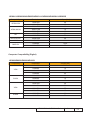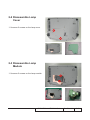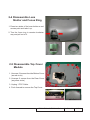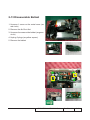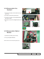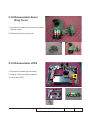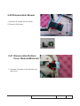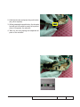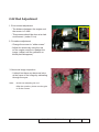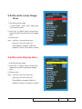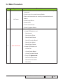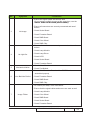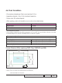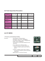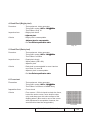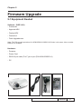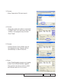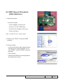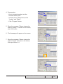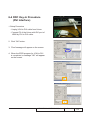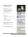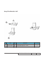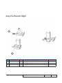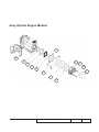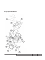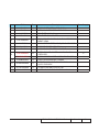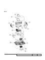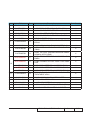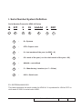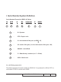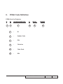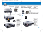
1
SERVICE MANUAL
HD80/HD80-LV/HD803-LV Series
HD80 Series
HD80, HD803, HD8000, HD800X
HD80-LV Series
HD80-LV, HD8000LV, HD805S
HD803-LV Series
HD803-LV, HD806, HD800X-LV, HD803S
Date
Revise Version
Description
2007.07.19
V1.0
Initial Issue
2007.08.07
V2.0
Edit 2-1, 2-4, 2-11, 4-9
2007.10.07
V3.0
Add HD803
2008.06.13
V4.0
Add HD80-LV, HD803-LV
2009.4.27
V5.0
1. Add HD8000,
����������������������������������������
HD800X, HD800X-LV, HD806,
HD803S, HD805S, HD8000LV.
2. Add “Re-write Display Hour“ in CH 2.
3. Modify “Auto Shut Down” in CH 3.
4. Modify “Light Leak” in CH 4-6.
2010.02.22
V6.0
Modify CH 4 "Defect specification table"
Copyright February, 2010. All Rights Reserved P/N: 36.87Z05G001
SI :
TSE:
Check:
Approved:
HD80/HD803-LV/HD80-LV Comparison List
Model
Part
HD803-LV
80.87Z06G021
(�����
EMEA�)
80.87Z06G031
(����
USA�)
70.87Z21GR01
(USA)
70.87Z21GR11
(EMEA)
FORMATTER BD
SCALER BD
ENGINE MODULE
COLOR WHEEL
MODULE
DMD
HD80
70.87Z19GR01
HD80-LV
80.87Z06G011
70.87Z25GR01
(USA)
70.87Z35GR01
(EMEA)
70.87Z29GR01
(USA/EUROPE/UK)
70.87Z19GR01
(Others)
70.85H24GR01
48.87CDMGD01
70.87Z31GR01
(USA)
70.87Z32GR01
(EMEA)
70.87Z19GR01
70.87Z40GR01
48.87ZDMGD01
48.87CDMGD01
HD80 Series Comparison List
Part
Model
HD80
HD8000
HD803
HD800X
80.87Z06G003
80.87Z06G002
80.87Z06G011
80.87Z01G004
80.87Z01G003
70.87Z35GR01
80.87Z06G021
FORMATTER
BD
(EMEA)
80.87Z06G031
( USA�)
SCALER BD
70.87Z21GR01
(USA)
70.87Z21GR11
(EMEA)
ENGINE
MODULE
70.87Z19GR01
70.87Z29GR01
DMD
48.87CDMGD01
48.87ZDMGD01
HD80/HD80-LV/HD803-LV Series Confidential
HD803-LV Series Comparison List
Model
Part
HD800X-LV
SCALER
BD
70.87Z35GR01
ENGINE
MODULE
HD806
70.87Z25GR01
70.87Z29GR01
DMD
HD803-LV
48.87CDMGD01
HD803S
70.87Z25GR01
(USA)
70.87Z26GR01
70.87Z35GR01
(EMEA)
70.87Z29GR01
(USA/EUROPE/UK)
70.87Z19GR01
(Others)
70.87Z19GR01
48.87ZDMGD01
HD80-LV Series Comparison List
Model
Part
SCALER BD
HD805S
HD8000LV
HD80-LV
70.87Z27GR01
70.87Z33GR01
70.87Z31GR01(USA)
70.87Z32GR01(EMEA)
HD80/HD80-LV/HD803-LV Series
Confidential
II
Preface
This manual is applied to HD80/HD80-LV/HD803-LV Series projection system. The
manual gives you a brief description of basic technical information to help in service and
maintain the product.
Your customers will appreciate the quick response time when you immediately identify
problems that occur with our products. We expect your customers will appreciate the
service that you offer them.
This manual is for technicians and people who have an electronic background. Please
send the product back to the distributor for repairing and do not attempt to do anything that
is complex or is not mentioned in the troubleshooting.
Notice:
The information found in this manual is subject to change without prior notice. Any
subsequent changes made to the data herein will be incorporated in future edition.
HD80/HD80-LV/HD803-LV Series Service Manual
Copyright February, 2010
All Rights Reserved
Manual Version 6.0
HD80/HD80-LV/HD803-LV Series
Confidential
II
Table of Content
Chapter 1
Introduction
Highlight
1-1
Compatible Mode
1-4
Chapter 2 Disassembly Process
Equipment Needed & Product Overview
2-1
Disassemble Lamp Cover
2-2
Disassemble Lamp Module
2-2
Disassemble Lens Shelter and Focus Ring
2-3
Disassemble Top Cover Module
Disassemble Keypad Board
Disassemble Vent
Disassemble Rear Cover
2-3
2-4
2-4
2-5
Disassemble Formatter Board
2-5
Disassemble IRIS Module
2-6
Disassemble Scaler Board
2-6
Disassemble Fan Shetter1 2-7
Disassemble Ballast
2-8
Disassemble Fan Shetter2
2-9
Disassemble Optical Module
2-9
Disassemble Color Wheel 2-10
Disassemble DMD Chip
2-10
Disassemble Zoom Ring Cover
2-11
Disassemble LVPS
2-11
Disassemble Blower
2-12
Disassemble Bottom Cover Module & Elevator
2-12
HD80/HD80-LV/HD803-LV Series Confidential
III
Rod Adjustment
2-14
Re-write Lamp Usage Hour
2-15
�����������������������������������������
Re-write Display Hour
2-15
Chapter 3
Troubleshooting
Chapter 4
LED Lighting Message
Main Procedure
3-1
3-2
Function Test & Alignment Procedure
Test Equipment Needed
4-1
Service Mode
4-1
OSD Reset
4-2
Test Condition
4-2
Test Inspection Procedure
4-3
PC Mode
4-3
Calibration
4-7
IRIS Test
4-9
Optical Performance Measure
4-10
Video Performance
4-12
Other
4-13
Chapter 5 Firmware Upgrade Equipment Needed
5-1
Setup Procedure
5-2
Firmware Upgrade Procedure
5-2
HD80/HD80-LV/HD803-LV Series
Confidential
IV
Chapter 6 EDID Upgrade
EDID Introduction
6-1
Equipment Needed
6-2
Setup Procedure (VGA Port)
6-3
DDC Key-In Procedure (VGA Interface)
6-3
Setup Procedure (DVI Port)
6-5
DDC Key-In Procedure (DVI Interface)
6-5
Make sure procedure
6-6
Setup Procedure (HDMI1 Port)
6-7
DDC Key-In Procedure (HDMI1 Interface)
6-7
Make sure procedure
6-8
Setup Procedure (HDMI2 Port)
6-8
DDC Key-In Procedure (HDMI2 Interface)
6-8
Make Sure Procedure
6-9
Appendix A Recommended Spare Parts
I
Appendix B Serial Number System Definition
PCBA Code Definition
XIV
XV
HD80/HD80-LV/HD803-LV Series Confidential
Chapter 1
Introduction
1-1 Highlight
No
Item
Description
1
Dimensions (L x W x H)
- 411 x 311 x 116 (mm)
2
Weight
- approx. 10 lbs (< 11lbs)
3
Tilt Angle
- +5/-2 degree with elevator mechanism
4
Power Supply
5
Light Source
6
Keystone correction
7
Cooling system
8
Brightness
- Universal AC 100--240V; 50 / 60 Hz with PFC input
- Max. 430W (HD80/HD803/HD8000/HD800X)
Max. 435W (HD80-LV/HD803-LV/HD8000LV/HD805S/
HD806/HD800X-LV/HD803S)
- provide for Philips 300W 1.3 arc UHP E21.8 lamp at brite
mode,255W at ECO mode.
- Lamp could be changed by customer, but should follow the
user manual instruction.
- Replaceable Lamp should be provided by Coretronic or its
autherized agencies
- ±5° Vertical (HD80/HD803/HD8000/HD800X)
±15° Vertical (HD80-LV/HD803-LV/HD8000LV/HD805S/
HD806/HD800X-LV/HD803S)
(according to Pixelworks PW392 scalar spec)
- Advanced air flow
- One fan/ two blowers(in projector) with low system acoustic
noise level
- Temperature control circuits with adaptive voltage control
fan speed
- Max touch temperature follows UL60950 regulation
HD80/HD803/HD8000/HD800X:
- Maximum 1,200 ANSI Lumens
- Typical 1,000 (HD80/HD8000/HD800X)/
940(HD803) ANSI Lumens
- Minimum 800 ANSI Lumens
HD80-LV/HD8000LV/HD805S:
- Maximum 2,200 ANSI Lumens
- Typical 1,740 ANSI Lumens
- Minimum 1,550 ANSI Lumens
HD803-LV/ HD806/HD800X-LV/HD803S:
- Typical 1,479 ANSI Lumens
- Minimum 1,320 ANSI Lumens
HD80/HD80-LV/HD803-LV Series
Confidential
1-
No
Item
Description
HD80/HD803/HD8000/HD800X: - 1,0000:1 full on\full off (with high contrast iris setting),
- 4,000:1 (Maximum)
- 2,500:1(HD80/HD8000/HD800X)���������
(Typical)
2,200:1(HD803) (Typical)
- 2,000:1 (Minimum)
HD80-LV/HD8000LV/HD805S:
- 7,000:1 full on\full off (with high contrast iris setting),
- 3,300:1 (Maximum)
- 2,700:1 (Typical)
- 2,200:1 (Minimum)
HD803-LV/HD806/HD800X-LV/HD803S:
- 7,000:1 full on\full off (with high contrast iris setting),
- 2,500:1 (Maximum)
- 2,000:1 (Typical)
- 1,500:1 (Minimum)
- 80% Japan standard (Maximum),
- 75% Japan standard (Typical),
- 65% Japan standard (Minimum)
9
Contrast
10
Uniformity
11
Throw ratio
-1.85 – 2.22:1 distance/width
12
Lamp door protection
- Lamp power supply shut off automatically when door open
13
Projection lens
- F/ 2.6~2.82, f = 39.12~46.94 mm. 1.2X Zoomed Focal
Lens
HD80/HD803/HD8000/HD800X:
- 1,700 hours typical, 50% survival rate in normal mode
-2
,200 hours typical in Eco mode
14
Lamp life
HD80-LV/HD8000LV/HD805S/HD803-LV/HD806/
HD800X-LV/HD803S:
- 1,250 hours typical, 50% survival rate in normal mode
- 1,600 hours typical in Eco mode
15
System controller
- Dual DDP3021, DAD1000, PMD1000 for 1080p DMD.
HD80/HD80-LV/HD803-LV Series
Confidential
1-
No
Item
Description
16
Video compatibility
- Standards:
NTSC : NTSC M/J, NTSC 4.43
PAL : PAL B/D/I/G/H, PAL M, PAL N
SECAM : SECAM B/D/G/K/L
SDTV : 480i, 480p, 576i, 576p,
HDTV :
- HD80/HD803/HD8000/HD800X:
7
20p(50HZ), 720p(60HZ), 1080i(50HZ),
1080i(60HZ) and 1080p(60HZ)
- HD80-LV/HD8000LV/HD805S/HD803-LV/HD806/
HD800X-LV/HD803S:
7
20p(50Hz), 720p(60Hz), 1080i(50Hz),
1080i(60Hz), 1080P (50 & 60Hz) and 1080p-24
17
Intelligent zoom
- By using “TI DDP3021” Chips to provide excellent quality
zooming.
18
SXGA / Compression
- By using “DDP3021” Chips to compress SXGA image into
XGA display
Power consumption
HD80/HD803/HD8000/HD800X:
- Full power( normal ): typical 425W+/-10% at 110V AC
- ECO power(ECO): typical 360W+/-10% at 110V AC
- Standby mode: < 7 W at 110V AC
H D 8 0 - LV / H D 8 0 0 0 LV / H D 8 0 5 S / H D 8 0 3 - LV / H D 8 0 6 /
HD800X-LV/HD803S:
- Full power( normal ): typical 435W Max at 110V AC
- ECO power(ECO): typical 375W Max at 110V AC
- Standby mode: < 14 W at 110V AC
19
HD80/HD80-LV/HD803-LV Series Confidential
1-
1-2 Compatible Mode
Computer Compatibility (Analog)
HD80/HD803/HD8000/HD800X
Compatibility
Resolution
V-Sync [Hz]
640x350
70
640x350
85
640x400
85
640x480
60
640x480
72
640����
x480
75
640����
x480
80
720x400
70
720x400
85
800x600
56
800x600
60
800x600
72
800x600
75
800x600
85
1024x768
60
1024x768
70
1024x768
75
1024x768
85
1280x720
60
1280 x 768
60
1280 x 768
85
1280x1024
60
1280x1024
75
SXGA+
1400x1050
60
UXGA
1600x1200
60
VGA
SVGA
XGA
WXGA*
WXGA
SXGA
HD80/HD80-LV/HD803-LV Series
Confidential
1-
HD80-LV/HD8000LV/HD805S/HD803-LV/HD806/HD800X-LV/HD803S
Compatibility
Resolution
V-Sync [Hz]
VESA SXGA+
1024x768
1024x768
1280 x 768
1280 x 768
1280 x 768
1280x720
1280x720
1400x1200
60
85
60
72
85
60
72
60
*MAC
1152x870
60
640x480
75.06
1024x768
75
VESA XGA
VESA WXGA
HD
MAC G4
Computer Compatibility (Digital)
HD80/HD803/HD8000/HD800X
Compatibility
VGA
SVGA
XGA
WXGA
Resolution
V-Sync [Hz]
640x480
60
640x480
72
640x480
75
640x480
85
800x600
60
800x600
75
800x600
85
1024x768
60
1024x768
70
1024x768
75
1024x768
85
1280x768
60
1280x768
70
HD80/HD80-LV/HD803-LV Series Confidential
1-
Compatibility
Resolution
V-Sync [Hz]
1280 x 720
60
1280 x 1024
60
1280 x 1024
75
SXGA+
1400x1050
60
UXGA
1600x1200
60
HD
HD80-LV/HD8000LV/HD805S/HD803-LV/HD806/HD800X-LV/HD803S
Compatibility
Resolution
V-Sync [Hz]
800x600
60
800x600
72
800x600
75
1024x768
60
1024x768
70
1024x768
75
VESA WXGA
1280 x 720
60
VESA SXGA+
1400x1200
60
1920x1080
24
1920x1080
60
VESA SVGA
VESA XGA
*HD
HD80/HD80-LV/HD803-LV Series
Confidential
1-
Chapter 2
Disassembly Process
2-1 Equipment Needed & Product Overview
1. Screw Bit (+) :107
2. Hex Sleeves 5mm
3. Hex Sleeves 8mm
4. Tweezers
5. Projector
* Before you start: This process is protective level II. Operators should wear electrostatic chains.
* Note:
1
. If you need to replace the scaler board, you have to record the lamp usage hour.
2. W
hen changing new scaler board, you have to get into the service mode( please refer to
the section 4-2) and choose "Temperature" , then hold the "Enter" key to adjust Left(-) and
Right(+).
HD80/HD80-LV/HD803-LV Series
Confidential
2-
2-2 Disassemble Lamp
Cover
1. Unscrew 2 screws on the lamp cover
2-3 Disassemble Lamp
Module
1. Unscrew 2 screws on the lamp module
HD80/HD80-LV/HD803-LV Series
Confidential
2-
2-4 Disassemble Lens
Shelter and Focus Ring
1. Press two sides of the lens shelter as red
arrows point and take it up.
2. Turn the focus ring in counter-clockwise
way and pull out of it.
2-5 Disassemble Top Cover
Module
1. Unscrew 13 screws from the Bottom Cover.
(as red circle)
2. Unscrew 2 screws from the Rear Cover.
(as yellow circle)
3. Unplug 1 FPC Cable.
4. Push forward to remove the Top Cover
HD80/HD80-LV/HD803-LV Series Confidential
2-
2-6 Disassemble Keypad
Board
1. Take off EMI type. (as yellow square)
2. Unscrew 10 screws. (as red circle, three of them on keypad)
3. Unplug 1 FPC cable
4. Remove the Keypad Board.
Note: EMI type can be recycled.
2-7 Disassemble Vent
1. Unscrew 1 screw on the left vent (as red
circle)
2. Remove the left vent
3. Unscrew 2 screws on the right vent (as
yellow circle)
4. Remove the right vent
HD80/HD80-LV/HD803-LV Series
Confidential
2-
2-8 Disassemble Rear Cover
1. Unscrew 4 hex screws (as red circle)
2. Remove the rear cover.
2-9 Disassemble Formatter
Board
1. Unscrew 6 screws (as red circle)
2. Unplug 11 wires (as yellow square)
3. Remove the formatter board
HD80/HD80-LV/HD803-LV Series Confidential
2-
2-10 Disassemble IRIS
Moduel
1. Unscrew 2 screws on the IRIS module
2. Remove the IRIS module
2-11 Disassemble Scaler
Board
1. Unscrew 1 screw (as red circle)
2. Unplug 1 FPC cable (as yellow square)
3. Remove the scaler board
Note: The switch should be at “on”location when
assembling or replacing the scaler board. (the
same direction as red arrow point )
HD80/HD80-LV/HD803-LV Series
Confidential
2-
2-12 Disassemble Fan
Shelter1
1. Unscrew 1 screw (as red circle)
2. Uplug 1 FPC calble (as yellow square)
3. Remove keypad connector board
4. Unscrew 1 screw (as blue circle)
5. Remove the shelter
6. Unscrew 3 screws (as green circle)
7. Remove the fan1
HD80/HD80-LV/HD803-LV Series Confidential
2-
2-13 Disassemble Ballast
1. Unscrew 1 screw on the metal cover (as
red circle)
2. Remove the Air-Duct first
3. Unscrew 4 screws on the ballast (as green
circle)
4. Unplug 2 plugs (as yellow square)
5. Remove the ballast
HD80/HD80-LV/HD803-LV Series
Confidential
2-
2-14 Disassemble Fan
Shetter2
1. Unscrew 2 screws on the metal cover (as
red circle)
2. Pull up to remove the metal cover
3. Unscrew 2 screws on the airtight bracket (as yellow circle)
4. Pull up to remove the airtight bracket and
fan
2-15 Disassemble Optical
Module
1. Unscrew 6 screws (as red circle)
2. Lift up the Optical Module
Note: Avoid to touch the Optical glass part
HD80/HD80-LV/HD803-LV Series Confidential
2-
2-16 Disassemble Color
Wheel
1. U nscrew 2 screws (as red circle) to
disassemble Color Wheel Module.
2. Unscrew 1 screw (as yellow circle)
to disassemble Photo Sensor Board from
Color Wheel Module.
3. Remove the color wheel
Note: Avoid to touch the glass parts in color
wheel.
2-17 Disassemble DMD Chip
1. U nscrew 4 screws on the heatsink
bracket.
Note: - The manner of placing a DMD mask
- Use an electrostatic ion gun to puff the
engine room in the DMD mask
- If there are scrapes or dirt on the DMD
chip, use an electrostatic ion gun to
clean it.
- Double check and see if the pin is out of
shape.
HD80/HD80-LV/HD803-LV Series
Confidential
2-10
2-18 Disassemble Zoom
Ring Cover
1. Unscrew 2 screws on the zoom ring cover
(as red circle)
2. Remove the zoom ring cover
2-19 Disassemble LVPS
1. Unscrew 6 screws (as red circle)
2. Unplug 1 wire (as yellow square)
3. Lift up the LVPS
HD80/HD80-LV/HD803-LV Series Confidential
2-11
2-20 Disassemble Blower
1. Unscrew 2 screws (as red circle)
2. Remove the blower
2-21 Disassemble Bottom
Cover Module&Elevator
1. Unscrew 3 screws on the elevator (as
red circle)
HD80/HD80-LV/HD803-LV Series
Confidential
2-12
2. Hold the elevator and press the push button
(as yellow square)
3. When pressing the push button, the elevator
foot will get loose and be easily to be pulled
down to separate the elevator.
4. Take out the long spring and separate all
parts of the elevator.
HD80/HD80-LV/HD803-LV Series Confidential
2-13
2-22 Rod Adjustment
1. Environment adjustment
A
- The distance between the engine and
the screen is 2.44M
- This process should be done at a dark
environment. (under 5 Lux)
2. Procedure adjustment
- Change
the screen to “white screen.”
- Adjust the screws by using the rod
on the engine module to readjust the
image. (adjust until the yellowish or
bluish parts disappear.)
3. Abnormal image inspection
A
- It should not have any abnormal color
at the frame of the image by estimating
through the eyes.
Note: - Avoid over adjusting the rod.
- After the opration, please use the glue
to fix the screws.
HD80/HD80-LV/HD803-LV Series
Confidential
2-14
2-23 Re-write Lamp Usage
Hour
1. Get into service mode.
-P
ress (Power→Left→Left→Up) to get
into service mode
2. Use “Left” or “Right” key to re-write the
lamp hour back to previous lamp usage
hour.
3. Choose exit.
Note: - Left key = decrease lamp hour
Right key =increase lamp hour
- Take HD80 for example, HD80-LV/
HD803-LV series is the same as HD80.
2-24 Re-write Display Hour
1. Get into service mode.
2. Use “Left” or “Right” key to re-write the
display hour back to previous display
hour.
3. Choose exit.
Note: - Left key = decrease lamp hour
Right key =increase lamp hour
- Take HD80 for example, HD80-LV/
HD803-LV series is the same as HD80.
HD80/HD80-LV/HD803-LV Series Confidential
2-15
Chapter 3
Troubleshooting
3-1 LED Lighting Message
Power LED
(Blue)
Message
Power LED
(Red)
Temp LED
(Blue / Red)
Lamp Led
(Blue / Red)
(Blue)
(Blue)
(Blue)
(Blue)
Flashing
(Blue)
Flashing
(Blue)
Standby State
(input power cord)
Warming
Normal Mode
Cooling
Flashing
Error
(Lamp failed)
(Red)
Error
(Fan failed)
Flashing
(Red)
Error
(Over Temp.)
(Red)
Light on
Light off
HD80/HD80-LV/HD803-LV Series
Confidential
3-
3-2 Main Procedure
No
Procedure
Symptom
- Ensure the Power Cord and AC Power Outlet are securely
connected
- Check Lamp Cover and Interrupt Switch
- Ensure all connectors are securely connected and aren’t
1
No Power
broken
- Check Lamp Driver
- Check LVPS
- Check Scaler Board
- Check Formatter Board
- Check LED Status
a. Lamp LED lights on red
- Check Lamp
- Check Lamp Driver
- Check Scaler Board
- Check Formatter Board
- Check Color Wheel
2
Auto Shut Down
- Check Photo Sensor
b. Lamp LED flashes red
- Check Fan
- Check Scaler Board
- Check Formatter Board
c. Temp LED �������������
lights on red
- Check Thermal Sensor
- Check Thermal Switch
- Check Fan
HD80/HD80-LV/HD803-LV Series
Confidential
3-
No
Procedure
Symptom
- Ensure the Signal Cable and Source work
(If you connect multiple sources at the same time, use the
“Source”
��������� button
��������������������������������������
on the control panel to switch)
- Ensure all connectors are securely connected and aren’t
broken
3
No Image
- Check Scaler Board
- Check Formatter Board
- Check DMD Board
- Check Color Wheel
- Check DMD Chip
- Ensure all connectors are securely connected and aren’t
broken
- Check Lamp Module
4
No Light On
- Check Lamp Driver
- Check LVPS
- Check Scaler Board
5
Mechanical Noise
6
Line Bar/Line Defect
- Check Formatter Board
- Check Color Wheel
- Check Fan Module
- Check if the Formatter Board and the DMD Board are
assembled properly
- Check Formatter Board
- Check DMD Board
- Check DMD Chip
- Do “Reset (All data)” of the OSD Menu
- Ensure that the signal cables and source are work as well
- Check Lamp Module
7
Image Flicker
- Check Color Wheel
- Check DMD Board
- Check Scaler Board
- Check Formatter Board
HD80/HD80-LV/HD803-LV Series
Confidential
3-
No
Procedure
Symptom
- Do “Reset (All data)” of the OSD Menu
- Adjust Color Wheel Index
8
Color Abnormal
- Check Scaler Board
- Check Formatter Board
- Check Color Wheel
- Ensure the projection screen without dirt
- Ensure the projection lens is clean
9
Poor Uniformity/
Shadow
- Ensure the Brightness is within spec
- Check rod alignment
- Check Engine Module
- Ensure the projection screen without dirt
- Ensure the projection lens is clean
10
Dead Pixel/Dust
(Out of spec.)
- Clean DMD Chip and Engine Module
- Check DMD Chip
- Check Engine Module
- Ensure that the signal cables and source work as well.
11
Garbage Image
- Check Scaler Board
- Check Formatter Board
- Check DMD Board
- Remote Control
12
13
Remote Control/
Control Panel Failed
Function Abnormal
a. Check Battery
b. Check Remote Controller
c. IR receiver
d. Check Scaler Board
- Control Panel
a. Check IR connector
b. Check Scaler Board
- Do “ Reset (All data)” of the OSD Menu
- Check Scaler Board
- Check Formatter Board
- Check DMD Board
HD80/HD80-LV/HD803-LV Series
Confidential
3-
No
Procedure
Symptom
- Check IRIS module connector.
14
IRIS Fail
- Check IRIS module
- Check Formatter Board.
HD80/HD80-LV/HD803-LV Series
Confidential
3-
Chapter 4
Function Test & Alignment Procedure
4-1 Test Equipment Needed
- IBM PC with XGA resolution
- Equipped “Component”, “S-Video” , “Composite” ,"DVI-I", "VGA", "SCART" and "HDMI."
- HDTV Source (720P / 50HZ, 720P / 60HZ, 1080i / 50HZ, 1080i / 60HZ, 1080P / 60HZ)
- Minolta CL-100
- Quantum Data 802B or CHROMA2327 (Color Video Signal & Pattern Generator)
- After changing parts, check the information below.
4-2 Service Mode
1. Turn on the projector and input the signal
2. Do the following actions sequentially to get into service mode menu
- Press "Power","Left","Left" and "Up" continuous.
4-3 OSD Reset
1. After final QC step, we have to erase all saved change again and restore the OSD
default setting. The following actions will allow you to erase all end-users' settings and
restore the default setting:
(1) Please get into OSD menu.
(2) Execute "Reset" function.
HD80/HD80-LV/HD803-LV Series
Confidential
4-
4-4 Test Condition
- Circumstance brightness: Dark room less than 5.0 lux.
- Inspection distance: 1.8m~2.5m functional inspection.
- Screen size: 60 inches diagonal
- After repairing, each unit should be run-in (refer to the table below)
Symptom
Normal repair
NFF
Auto shutdown
Run-in Time
2 hours
4 hours
6 hours
- Get into Burn-In Mode
* Cycle setting is based on the defect symptoms. ie: If it is NFF, the run-in time is 4 hours. You have
to set the lamp on for 50 min. and lamp off for 10 min for 4 cycles.
Press power > left > left > up
Choose Burn-In Test > enter
Lamp On (Min)
Press right key to adjust the time (50)
Lamp Off (Min)
Press right key to adjust the time (10)
Set burn in cycle
Press right key to adjust the cycle
After setting up the time, choose Burn-In mode and hit enter
Screen Defects (While replacing DMD Chip, DMD BD and MB)
Frame
< Figure: Zone A, Zone B & Frame(as green line) Definition,
Active area=Zone A+ Zone B >
HD80/HD80-LV/HD803-LV Series
Confidential
4-
4-5 Test Inspection Procedure
Charge parts
Update
Scaler BD
FW
Version Update
v
v
Color Wheel Index
v
PC
Calibration
v
YPbPr
Calibration
v
Color Wheel
Lamp Module
v
Reset lamp hour
v
Factory Reset
v
EDID
v
Re-write Lamp
Hour Usage
v
v
4-6 PC MODE
1. Frequency and tracking boundary
Procedure - Test equipment: video generator.
- Test signal: analog 1920 x 1080@60Hz -T
est Pattern: general-1 (1920 x 1080@60Hz)or
master (1920 x 1080@60Hz).
- Check and see if the image sharpness is wellperformed.
- If not re-adjust by the following steps:
(1) Select "Frequency" function to adjust the
total pixel number of pixel clock in one line
period.
(2) Select "Tracking" function and use right or
left arrow key to adjust the value to minimize
video flicker.
General-1
- Adjust Resync or Frequency/Tracking/
HD80/HD80-LV/HD803-LV Series
Master
Confidential
4-
H. Position/V. Position to the inner screen.
Inspection item
- Eliminate visual wavy noise by Rsync, Frequency or Tracking selection.
- Check if there is noise on the screen.
- Horizontal and vertical position of the video
should be adjustable to the screen frame.
Criteria
- If there is noise on the screen, the product is
considered as failure product.
- If there is noise on the screen, use auto or
manual “frequency” function or “tracking” function to adjust the screen.
- ����������������������������������������������������
Make sure the PC mode functions well,
including that frequency and auto detected functions are workable.
2. Light Leak
Procedure
- Test equipment: video generator.
- Test signal: analog �����
1920 x�� 1080@60Hz ��
������������ - Test Pattern: gray 10 pattern
- Check if the light leaks.
* Light leak on reflective edge, eye-catcher,
bondwires and exposed metal.
Inspection item
- Light leak check.
- Bright blemish (dirty).
Criteria
- Bright blemish is unacceptable in zone A and no
more than 4 in zone B.
Gray 10
- Ref.� Defect
���������������������������
specification table.
3. Blemish (Dark)
Procedure
- Test equipment: video generator.
- Test signal: analog �����
1920 x�� 1080@60Hz ��
������������ - Test Pattern: blue 60
Inspection item
- Dark blemish check.
Criteria
- The dark blemish is unacceptable in zone A and
no more than 4 in zone B under blue 60 pattern.
HD80/HD80-LV/HD803-LV Series
Blue 60
Confidential
4-
4. Dead Pixel (Bright pixel)
Procedure
- Test equipment: video generator.
- Test signal: analog �����
1920 x�� 1080��������
������������
@60Hz.
- Test Pattern: Gray 10
Inspection item
- Bright pixel check.
-�� ���������������
Adjacent pixel.
Criteria
- Bright pixel is unacceptable.
-�� Adjacent
��������������������������������
pixel is unacceptable.
- Ref. the
���� Defect
����������������������������
specification table.�
Gray 10
5. Dead Pixel (Dark pixel)
Procedure - Test equipment: video generator.
- Test signal: analog �����
1920 x�� 1080��������
������������
@60Hz.
- Test Pattern: full white
Inspection item
- Dead pixels check.
- White pattern (IRE=100)
- Adjacent pixel.
Criteria
- Dark pixel is unacceptable in zone A and no
more than 2 in zone B.
- Adjacent pixel is unacceptable.
- Ref. ����
the ����������������������������
Defect specification table.�
Full white
6. Focus test
Procedure
- Test equipment: video generator.
- Test signal: analog �����
1920 x�� 1080�����
���������
@60Hz
- Test Pattern: full screen or MEME Sony
Inspection item
- Focus check
Criteria
-From screen 1.5 M via visual to check the focus,
look at the entire screen, focus shall be clear,
crisp, and sharp over the entire surface of the
display pattern. (Blur word on one of the corner
after adjustment is acceptable. However, the
word should at least be recognizable.)
HD80/HD80-LV/HD803-LV Series
Full screen
Confidential
4-
7. Color performance
Procedure
Inspection item
Criteria
- Test equipment: video generator.
- Test signal: DVI (HDMI) 720p,1080i
- Test Pattern: Master, In focus II or SMPTE
RP-133
MEME Sony
* Please refer to 4-2 to get into service mode.
Use 720P & 1080i signal, master pattern to do
HDTV test. Color cannot discolor to purple and
blue.
- Check if each color level is well-functioned.
- Color saturation
- Screen appears normal. It should not have any
abnormal condition, such as lines appear on the
screen and so on.
- Color appears normal.
- It is acceptable to have few lines flashing at the
center and on the edge of 1080i image. However, rest of the image should appear stable.
- RGBW should all appear normal on the screen
and sort from R -G-B-W.
- Color levels should be sufficient and normal.
(the unidentified color levels on both left and
right sides should not over 8 color levels.)
- Gray level should not have abnormal color or
heavy lines.
- �
Make
��������������������������������������������
sure the PC mode functions well, including that frequency and auto detected functions
are workable.
Master
InFocus II
/ 64 gray RGBW
SMPTE RP-133
4-7 Calibration
1. YPbPr calibration
Procedure - Test equipment: video generator.
HD80/HD80-LV/HD803-LV Series
Confidential
4-
- Once main board is changed, YPbPr calibration
should be done as well.
(1) Test signal: 720P
(2) Test Pattern: SMPTE BAR
- Note
(1) Calibration pattern should be in fill screen
mode.
(2) Please refer to 4-2 to get into Service Mode
and OSD Reset.
(3) Choose and access YPbPr Calibration for
correction in service mode. Choose “menu”
to leave the service mode after all.
* Note: ADC adjustment can only be used once.
If there is any circumstances which needs to
be re-adjust, the adjustment is only effective
when you adjust at the odd number of times.
Otherwise, the black will not be dark enough.
Check pattern
- Test signal: 720P
- Test pattern: In focus II or 64 gray RGBW
SMPTE BAR
* After finishing Video calibration adjustment,
check 64 gray RGBW pattern.
Inspection item
- Color saturation
Criteria
- There should not have any lack of RGBW. The
color should appear normal and sort in right
order.
- Color levels should be sufficient and normal.
(the unidentified color levels on both left and
In focus II / 64 Gray
RGBW
right sides should not over 8 color levels.)
- Gray level should not have abnormal color or
heavy lines.
2. PC calibration
Procedure - Test equipment: video generator
- Once main board is changed, PC calibration
should be done as well.
(1) Test signal analog: �����
1920 x1080��������
�������������
@60Hz HD80/HD80-LV/HD803-LV Series
Confidential
4-
(2) Test Pattern:16 Gray (�����
1920 x�� 1080������
����������
@60Hz)
- Note
(1) Calibration pattern should be in fill screen
mode.
�����
(2) Please refer to 4-2 to get into Service Mode
and OSD Reset.
(3) Choose and access PC Calibration for correction in service mode. Choose “menu” to
leave the service mode after all.
* Note: ADC adjustment can only be used once.
If there is any circumstances which needs to be
re-adjust, the adjustment is only effective when
you adjust at the odd number of times. Otherwise, the black will not be dark enough.
Check pattern - Test signal: analog �����
1920 ��x ���������
1080�����
@60Hz
- Test pattern: In focus II or 64 gray RGBW
* After finishing ADC adjustment, check 64 gray
RGBW pattern, adjust color wheel index in color
setting of service mode.
Inspection item
- Color saturation
Criteria
- There should not have any lack of RGBW. The
color should appear normal and sort in right
order.
- Color levels should be sufficient and normal.
(the unidentified color levels on both left and
right sides should not over 8 color levels.)
- ����������������������������������������������
Gray level should not have abnormal color or
heavy lines.
16 gray
In focus 2 / 64 gray
RGBW
Defect specification table
Order
1
2
Symptom
Bright pixel ( dots)
Pattern
Gray 10 pattern
Dark pixel(dots)
White pattern
Criteria
A+B=0
A=0
B≤2
HD80/HD80-LV/HD803-LV Series
Confidential
4-
Order
3
4
Symptom
Unstable pixel (dots)
Pattern
Any pattern
Criteria
A+B=0
Adjacent pixel (dots)
Any pattern
A+B=0
A=0
5
Dark blemish (Dirty)
Blue 60 pattern
B≤4
(diameter <1 inch)
A=0
6
Bright blemish (Dirty)
Gary 10 pattern
B≤4
(diameter <1 inch)
7
Bright dot on frame
Gray 10 pattern
≤1
4-8 IRIS Test
Procedure
- Get into the service mode
- Press "Power","Left","Left" and "Up" continuous.
-S
elect " IRIS 3 times test" founction, then the image will flash three
times.
HD80/HD80-LV/HD803-LV Series
Confidential
4-
4-9 Optical Performance Measure
Inspection Condition
- Environment luminance: 5 Lux
- Product must be warmed up for 3 minutes
- Distances from the screen: 2.44 M
- Screen Size: 60 inches diagonal
- Reset to default before measurement
1. Test equipment
Procedure - Test equipment: video generator.
- Test signal: analog ������������������
1920 x 1080�������
@60Hz.
2. Brightness
Procedure - Full white pattern
- Use CL100 to measure brightness values of
P1~P9.�������������������
�������������������������
- Follow the brightness formula to calculate
brightness values.
☼ Brightness Formula
Criteria
Avg. (P1+P2+P3+...+P9) x1.1
Full white pattern
- 440 ANSI Lumens
HD80/HD80-LV/HD803-LV Series
Confidential
4-10
3. Full On/Full Off Contrast
Procedure
- Full white pattern & full black pattern
- Use CL100 to measure brightness values of full
white pattern P5 & full black pattern B5 ( see image: full white)
- Follow Contrast formula to calculate contrast
values.
☼ Contrast Formula
P5/B5
note: P
5=center of white image
Criteria
Full black pattern
B5 = the center of black image.
- 2000:1
4. Uniformity
Procedure
- Full white pattern
- Use CL100 to measure brightness values of
P1~P9 (see image: full white).
- Follow the Uniformity formula to calculate
average values.
☼ Uniformity Formula
ANSI Uniformity = Avg. (P1, P3, P7, P9)
Criteria
P5
x 100%
- 65 %
HD80/HD80-LV/HD803-LV Series
Confidential
4-11
4-10 Video Performance
1. CVBS
Procedure - Test equipment: DVD player
- Test signal: CVBS
Inspection item
- Video performance test
Inspection Distance - 1.8M ~2.5M
Criteria
- Check any abnoraml color, line distortion or any
noise on the screen
Motion video
2. S-Video
Procedure
- Test equipment: DVD player
- Test signal: S-Video
Inspection item
- Video performance test
Inspection Distance - 1.8M ~2.5M
Criteria
- Check any abnoraml color, line distortion or any
noise on the screen
3. HDTV/ Component
Procedure - Test equipment: DVD player
- Test signal: YCbCr/YPbPr
Inspection item
- HDTV performance test
InspectionDistance - 1.8M ~2.5M
Criteria
- Check any abnoraml color, line distortion or any
noise on the screen
HD80/HD80-LV/HD803-LV Series
Confidential
4-12
4. HDMI Test
Procedure - Test equipment: DVD Player with HDMI output
- Test signal: 720p,1080i
Inspection item
- HDMI performance test
Inspection Distance - 1.8M ~2.5M
Criteria
- Ensure if the image is well performed and the
color can not discolor.
4-11 Others
1. Functional Inspection
Keypad button
- All keypad buttons must operate smoothly.
General- All OSD functions must be checked for functionality. When
OSD menu is displayed, there shall be no visible peaking,
ringing, streaking, or smearing artifacts on the screen.
Factory Default
Display Size
- The factory settings (with appropriate center, size, geometry
distortion, etc.) shall be displayed upon “Recall” is selected
from OSD
- All preset modes shall expand to full screen size using OSD
Horizontal and Vertical Size controls
Display Data Channel (DDC) - The purpose of the DDC test is to verify the DDC1/DDC2B
operation of the projector and to verify Plug & Play function.
Acoustic
- High pitch sound from cooling fan and color wheel is unacceptable.
HD80/HD80-LV/HD803-LV Series
Confidential
4-13
2. Check points for exterior and print pattern
Check item
Check point
Text & pattern
Missing letters & pattern or blurry prints are unacceptable.
Exterior
Dirt, scrape, water ripples and uneven color are unacceptable.
Button
Stuck buttons are unacceptable.
Focus ring
Focus ring is functioning smoothly.
Logo
Missing logo, missing prints and blurry prints are unacceptable
Screw
All screw sure be fixed and in right type.
Elevator
Elevator is well-functioned.
Stuck key is unacceptable.
Pedestal
Well-functioned
Lamp cover
It should be locked in the correct place.
Plastic parts
Safety or warning
label
Connector
All plastic parts can not be broken and damaged.
All safety and warning label should be visible, including all
contents.
All interface connector should be complete and workable.
HD80/HD80-LV/HD803-LV Series
Confidential
4-14
Chapter 5
Firmware Upgrade
5-1 Equipment Needed
Software : (DDP 3021)
- Pixelworks
- Appcode.HEX
- Flasher.HEX
- Flashall.inf
- Flash Upgrader.exe
Note: The FW upgrade procedure for HD80/HD80-LV/HD803-LV Series is the same. Here, we take
HD80 as an example.
Hardware :
- Projector
- Power Cord
- RS232 9 pin cable (F to F) pin to pin (P\N 42.86603G001-A)
- PC
HD80/HD80-LV/HD803-LV Series
Confidential
5-
5-2 Setup Procedure
1. Connect all ports
- Make sure power cord unplugged
- C
onnect PC Com Port and projector
RS232 Port by RS232 cable.
5-3 Firmware Upgrade
Procedure
1. Get into the "In System Program"
- Execute "FlashUpgrader.exe".
2. Firmware Upgrade
- T
he window of FlashUpgrader shows up
and click "Choose" to get the file directory.
HD80/HD80-LV/HD803-LV Series
Confidential
5-
3. Process
- Select "appcode.inf" file and open it.
4. Process
- S
elect the serial port which is connected
to HD80. Don't use other baud rate than
115200, or the program may not work.
- Click "Flash".
5. Process
- Connect Power Cord to HD80, then do
the upgrade process. Program will be
automatically run after 5 seconds.
6. F
inish
-C
lose FlashUpgrader program and unplug
Power Cord to finish firmware upgrade.
- Then get into the service mode to check
the firmware and see if it is correct.
HD80/HD80-LV/HD803-LV Series
Confidential
5-
Chapter 6
EDID Upgrade
6-1 EDID Introduction
Extended Display Identification Data is a VESA standard data format that contains basic
information about a display device and its capabilities, including vendor information,
maximum image size, color characteristics, factory pre-set timings, frequency range limits,
and character strings for the monitor name and serial number.
The information is stored in the display and is used to communicate with the system
through a Display Data Channel (DDC), which sites between the display device and the
PC graphics adapter. The system uses this information for configuration purposes, so the
monitor and system can work together.
Note: If a display device has digital input ports, like DVI or HDMI, but without EDID in its
main board, the display device will show no image while the input source is digital signal.
HD80/HD80-LV/HD803-LV Series
Confidential
6-
6-2 Equipment Needed
Software
- EDID.exe
- **-EDID-Axx.ini(Note: ** represents model name)
Hardware
- Projector
- HDMI(M) to DVI(F) Adapter P/N:42.82B13G001
- VGA to DVI cable P/N:42.83403.001
- RS-232 9 pin cable ( Male to Female) P/N:42.83C07G001
- EDID Fixture (JP3 must be closed) P/N:80.58704.001
- PC
- DVI to DVI cable P/N:42.59902.012
- Power adapter for fixture and power cord
Note: The EDID upgrade procedure for HD80/HD80-LV/HD803-LV Series are the same. Here, we
take HD80 as an example.
HD80/HD80-LV/HD803-LV Series
Confidential
6-
6-3 DDC Key-In Procedure
(VGA Interface)
P1
RS232 Cable
Adapter
JP1
1. Setup Procedure
- Connect all ports
-- Power adapter to fixture JP1
-- Fixture P1 to PC COM2 Port
-- Fixture P4 to Projector DVI-I port
-- Power on fixture
P4
VGA-DVI Cable
Note: Confirm JP3 is in “Close” status.
2. Double click "EDID" to execute EDID program.
3. Choose model
- In the port selection bar, please choose
the port you're using. Example: if you
use "COM2," choose COM2 in the port
selection.
- Click "Model."
- Choose the EDID file that responses to
the model you choose.
HD80/HD80-LV/HD803-LV Series
Confidential
6-
4. Programming
- Key in the serial number into the
barcode blank space.
- In"Write Source Select"item,select
“Analog” and “Digital”.
- Click "Program" button.
5. W
hen the message “Please change the
cable to Analog” is shown on the screen,
click “OK” button.
6. “Run”message will appear on the screen.
“
7. W
hen the message “Please change the
cable to Digital” is shown on the screen,
follow procedure 6-4.
“
HD80/HD80-LV/HD803-LV Series Confidential
6-
6-4 DDC Key-In Procedure
(DVI Interface)
1. Setup Procedure
- Unplug VGA to DVI cable from fixture.
- Connect P3 of the fixture with DVI port of HD80 by DVI to DVI cable.
2. Click “OK” button.
3. “Run”message will appear on the screen.
4. W
hen the EDID program for VGA to DVI
is completed, a message "OK" will appear
on the screen.
HD80/HD80-LV/HD803-LV Series
Confidential
6-
5. Check DVI-D EDID Information.
- Choose “Digital” and “Trans”in Read item.
“
- Press “Read” button to check EDID Information.
6. Check DVI-A EDID Information.
- Choose “Anlog” and “Trans”in Read item.
Unplug the DVI-DVI cable, then plug VGA-DVI cable.
- Press “Read” button to check EDID Information.
“
HD80/HD80-LV/HD803-LV Series Confidential
6-
6-5 DDC Key-In Procedure
(HDMI 1 Interface)
1. Setup Procedure
- Unplug DVI-DVI cable from fixture
- Plug DVI cable into P3 of fixture, connect DVI-HDMI adapter with DVI cable and then plug DVI-HDMI adapter into HD80 unit.
Note: Confirm JP3 is “Close” status.
2. Programming
- Key in the serial number into the barcode
blank space.
- I n"Write Source Select"item, select
“Digital”.
- Choose the port you're using.
- Click "Program" button.
3. W
hen the message “Please change the
cable to Digital” is shown on the screen,
then click“OK” button.
Note: “Run”message will appear on the screen.
4. When the EDID program is finished, a
message "OK" will appear on the screen.
HD80/HD80-LV/HD803-LV Series
Confidential
6-
5. Choose “Digital” and “Trans” in Read item. Click “Read” button to check EDID information.
“
6-6 D DC Key-In Procedure
(HDMI 2 Interface)
1. Setup Procedure
- Unplug DVI-HDMI adaptor, then plug into HDMI2 port.
Note: Confirm JP3 is “Close” status.
2. Programming
- Key in the serial number into the barcode
blank space.
- I n "Write Source Select" item, select
“Digital”.
- Choose the port you're using.
- Click "Program" button.
HD80/HD80-LV/HD803-LV Series Confidential
6-
3. W
hen the message “Please change the cable
to Digital” is shown on the screen, click “OK”
button.
Note: “Run” message will appear on the screen.
4. When the EDID program is finished, a message
"OK" will appear on the screen.
5. Choose “Digital” and “Trans” in Read item. Click “Read” button to check EDID information.
“
HD80/HD80-LV/HD803-LV Series
Confidential
6-
Appendix A
Buy Assy Base Housing
3
4
5
6
2
7
8
1
item
P/N
Rev
Description
1
75.85H04G001
A
BUY ASSY BASE HOUSING HD81
2
61.83C18G001
A
MESH FOR LAMP DRIVER EP910
3
41.83C13G001
A
EMI GASKET W10*L20
4
41.83C14G001
A
EMI TAPE W10*L45
5
52.83C09G001
A
AIR-TIGHT SPONGE-2 BOTTOM EP910
6
61.83C15G001
A
BOTTOM HEAT ISOLATION AL FOIL EP910
7
41.83C03G001
A
EMI TAPE W15*L90
8
41.83C04G001
A
EMI TAPE W15*L60
HD80/HD80-LV/HD803-LV Series
Parts Supply
V
Confidential
Buy Assy Rear Cover
1
4
5
2
3
item
P/N
Rev
Description
1
35.87Z01G001
A
IO LABLE PC 8B35 HD80
2
41.83C07G001
A
EMI GASKET W10*H15*L25
3
41.83J13G001
A
EMI GASKET W5*H7*L150mm PD527
4
75.87Z01G002
B
BUY ASSY REAR COVER MODULE HD80
5
61.87Z01G001
A
REAR COVER SHIELDING TINPLATE T=0.2
HD80
HD80/HD80-LV/HD803-LV Series
Parts Supply
Confidential
V
II
Buy Assy Right Cover
item
P/N
Rev
Description
1
75.85H08G001
A
BUY ASSY RIGHT COVER HD81
2
52.83C20G001
A
RUBBER AIR-TIGHT FOR RIGHT COVER
EP910
Parts Supply
HD80/HD80-LV/HD803-LV Series Confidential
V
III
Buy Assy Left Cover
1
2
item
P/N
Rev
Description
1
75.85H07G001
A
BUY ASSY LEFT COVER HD81
2
61.83C11G001
A
LEFT COVER MESH
HD80/HD80-LV/HD803-LV Series
Parts Supply
V
Confidential
IV
Assy Top Cover Module
4
2
3
1
item
P/N
1
42.00304G001
2
Rev
Description
Parts Supply
A
FFC KEYPAD TO FORMATTER BD 16P P=0.5
122mm HD80
V
80.87Z03G001
A
PCBA KEYPAD BOARD FOR HD80
V
3
70.87Z23GR01
A
ASSY TOP COVER MODULE HD80 (RMA)
V
4
85.WA123G050
D1
SCREW PAN TOP M3x5
HD80/HD80-LV/HD803-LV Series Confidential
Buy Assy Top Cover
3
2
1
item
P/N
Rev
Description
1
70.87Z23GR01
A
ASSY TOP COVER MODULE HD80 (RMA)
2
51.83C10G001
A
FRONT IR COVER EP910
3
61.83C07G001
A
TOP COVER SHIELDING
HD80/HD80-LV/HD803-LV Series
Parts Supply
Confidential
V
VI
Lamp Cover Module
1
item
P/N
Rev
Description
1
61.83C20G001
A
AL SHIELDING 0.1t FOR LAMP COVER
EP910
2
70.83C25GR01
A
ASSY LAMP COVER MODULE EP910 (RMA)
3
41.82G12G002
A
EMI GASKET W10*L20*H2.5mm
Parts Supply
HD80/HD80-LV/HD803-LV Series Confidential
V
VII
Buy Assy Zoom Ring
2
1
item
P/N
Rev
Description
1
51.82B40G001
A
ZOOM RING SPACER TEFLON 5100MP
2
75.85H02G002
A
B U Y A S S Y Z O O M R I N G C H R O M AT E
TREATMENT HD81
HD80/HD80-LV/HD803-LV Series
Parts Supply
Confidential
V
VIII
Assy Pre-Elevator Left
2
3
1
item
P/N
Rev
Description
1
51.83C17G001
A
ELEVATOR HOUSING
2
51.83C15G042
A
ELEVATOR PUSH LEFT HD80
3
61.85913G001
A
ELEVATOR SPRING
Parts Supply
HD80/HD80-LV/HD803-LV Series Confidential
V
IX
Assy Pre-Elevator Right
2
3
1
item
P/N
Rev
Description
1
51.83C17G001
A
ELEVATOR HOUSING
2
51.83C14G042
A
ELEVATOR PUSH RIGHT HD80
3
61.85913G001
A
ELEVATOR SPRING
HD80/HD80-LV/HD803-LV Series
Parts Supply
V
Confidential
Assy Elevator Foot
item
P/N
Rev
Description
Parts Supply
1
51.83C16G001
A
ELEVATOR BODY
V
2
51.83C21G041
A
ELEVATOR FOOT PC+ABS HD80
V
3
52.83C03G001
A
ELEVATOR FOOT RUBBER
V
4
85.1F123G060
A
SCREW PAN MECH W\SF M3*6 NI GR
5
52.83C21G001
A
SILIONE BUFFER 0.1t FOR ELEVATOR
HD80/HD80-LV/HD803-LV Series Confidential
XI
Assy Optical Engine Module
1
12
8
7
5
2
11
10
6
4
13
3
9
HD80/HD80-LV/HD803-LV Series
Confidential
XII
item
P/N
Rev
1
11.00500G001
A
CNNT 335P DMD LGA SOCKET 1080P HD81
48.87CDMGD01
A
DMD 1920*1080 PIXEL 0.95” 1080P LVDS
TYPE A DC2-8
V
48.87ZDMGD01
A
DMD 0.95” 1080P 2x LVDS DMD DC1-10 FOR
SUPER VALUE
V
3
51.85H43G001
A
INSULATOR MYLAR BETWEEN DMD-BD
AND HEAT SINK HD81
4
51.83C30G001
A
MYLAR INSULATION DMD HEAT SINK EP910
5
52.82B03G001
A
DUST COVER RUBBER F12 5100MP
6
52.85H11G001
A
SARCON GR-Hm 20mmx15mmx0.3mm DMD
THERMAL PAD
7
61.82B04G001
A
DMD HEATSINK AL 5100MP
8
61.85H14G001
E
DMD MASK HD81
9
61.85H34G001
A
DMD-PCB PRESSCOVER HD81
10
61.82B36G001
A
SCREW M3*10 IHSPC ‘’
11
61.82B37G001
A
HEAT SINK SPRING
12
70.87Z11G001
A
BUY ASSY OPTICAL MODULE HD80
13
70.87Z02G001
A
ASSY DMD BOARD MODULE HD80
2
Description
Parts Supply
HD80/HD80-LV/HD803-LV Series Confidential
XIII
Assy Optical Module
8
4
12
1
2
7
9
3
6
10
11
5
13
HD80/HD80-LV/HD803-LV Series
Confidential
XIV
item
P/N
1
23.82B20G001
A
BK7 CONDENSER-1 FOR SXGA+
2
23.82B20G011
A
S-TIH6 CONDENSER-2 FOR SXGA+
3
41.81U02G001
A
EMI TAPE W40*L40mm
4
41.82B14G001
A
EMI TAPE BMC COVER
5
75.87Z06G001
A
BUY ASSY ZOOM RING CHROMATE TREATMENT HD80
6
61.00075G001
A
SHOULDER SCREW M2*5φ2.5 *3.3 5100MP
7
70.85H19G001
A
ASSY ENGINE BASE HD81
8
70.82B06G001
A
ASSY ENGINE BOTTOM 5100MP
70.87Z40GR01
B
ASSY COLOR WHEEL MODULE HD80-LV
(SERVICE)
V
70.85H24GR01
B
ASSY COLOR WHEEL MODULE HD81(RMA)
V
10
70.82B29G001
A
ASSY LENS MODULE 5100MP
11
85.0A326G040
A
S C R E W D O U B L E F L AT M E C H M 2 . 6 * 4
φ4.5*0.5t BLACK
12
85.1A126G060
A
SCREW PAN MECH M2.6*6 Ni
13
85.0A122G030
A
SCREW DOUBLE FLAT MECH M2*3Ni
9
Rev
Description
Parts Supply
HD80/HD80-LV/HD803-LV Series Confidential
XV
D.C.
HD80/HD80-LV/HD803-LV Series
Confidential
XVI
item
P/N
Rev
1
75.85H04G001
A
BUY ASSY BASE HOUSING HD81
V
2
70.87Z23GR01
A
ASSY TOP COVER MODULE HD80 (RMA)
V
3
75.85H08G001
A
BUY ASSY RIGHT COVER HD81
V
4
75.85H07G001
A
BUY ASSY LEFT COVER HD81
V
5
75.87Z01G002
B
BUY ASSY REAR COVER MODULE HD80
V
6
51.83C07G041
A
LENS SHELTER HD80
V
7
51.83C36G002
A
TAPE KAPTON-5 FOR AIR DUCT 173*25
EP910
8
49.83C03G001
A
SUNON 50*10 AXIAL FAN/GM1205PFV3-8A
V
70.87Z19GR01
B
ASSY OPTICAL ENGINE MODULE HD80
(RMA)
V
70.87Z29GR01
A
ASSY OPTICAL ENGINE MODULE HD803
HD800X (WT87 LENS)
V
80.87Z06G021
C
PCBA FORMATTER BD 1080P FOR HD80
EMEA
V
80.87Z06G031
A
PCBA FORMATTER BD 1080P FOR HD80
USA
V
80.87Z06G002
B
PCBA FORMATTER BD 1080P FOR HD803
V
80.87Z06G003
B
PCBA FORMATTER BD 1080P FOR HD8000
V
80.87Z06G011
B
PCBA FORMATTER BD 1080P FOR HD80-LV
V
11
51.83C08G012
B
F O C U S R I N G C L A D D I N G C H R O M AT E
TREATMENT HD81
V
12
49.83C04G001
A
SUNON 9225 AXIAL FAN/KDE1209PTBX
V
13
75.85H14G001
A
ASSY LVPS LITEON HD81
V
14
SP.83C01G001
A
LAMP MODULE EP910
V
15
70.83C25GR01
A
ASSY LAMP COVER MODULE EP910 (RMA)
V
16
49.82B01G001
A
MISC BLOWER GB1206PTV2-AY R TYPE
V
9
10
Description
Parts Supply
HD80/HD80-LV/HD803-LV Series Confidential
XVII
Appendix B
I. Serial Number System Definition
Serial Number Format for HD80 Series
O
87Z
7
04 E
1
2
3 4
5
AAAA C
6
0001
7
8
1
:
O = Optoma
2
:
87Z = Project code
3
:
7 = Last number of the year (ex:2007 = 7)
4
:
04 = week of the year ( ex: the forth month of the year = 04)
5
:
E = Checking EDID code ( “E” = EDID code is for EMEA )
6
:
AAAA = not-defined
7
:
C = Manufacture factory (TW or CPC)
8
:
0001 = Serial code
EX: O87Z714AAAAAC0001
This label represents the serial number for HD80. It is produced for USA at CPC on
fourteenth week of 2007. Its serial code is 0001.
HD80/HD80-LV/HD803-LV Series
Confidential
XVIII
I. Serial Number System Definition
Serial Number Format for HD80-LV Series
Q
87Z
8
1
2
3 09 AAAAA
4
5
C 0001
6
7
1
:
Q = Optoma
2
:
87Z = Project code
3
:
8 = Last number of the year (ex:2008 = 8)
4
:
09 = week of the year ( ex: the ninth month of the year = 09)
5
:
AAAAA = not-defined
6
:
C = Manufactory Location (ex: C = China)
7
:
0001 = Serial code
EX: Q87Z809AAAAAC0001
This label represents the serial number for HD80-LV. It is produced for USA at CPC on
ninth week of 2008. Its serial code is 0001.
HD80/HD80-LV/HD803-LV Series Confidential
XIX
I. Serial Number System Definition
Serial Number Format for HD803-LV Series
Q
87Z
8
1
2
3 09 AAAAA
4
5
C 0000
6
7
1
:
Q = Optoma
2
:
87Z = Project code
3
:
8 = Last number of the year (ex:2008 = 8)
4
:
09 = week of the year ( ex: the ninth month of the year = 09)
5
:
AAAAA = not-defined
6
:
C = Manufactory Location (ex: C = China)
7
:
0000 = Serial code
EX: Q87Z809AAAAAC0001
This label represents the serial number for HD803-LV. It is produced for USA at CPC on
ninth week of 2008. Its serial code is 0000.
HD80/HD80-LV/HD803-LV Series
Confidential
XX
II.
PCBA Code Definition
PCBA Code for Projector
A B
1
XXXXXXXXXX
2
3
1
:
ID
2
:
Vendor Code
3
:
P/N
4
:
Revision
5
:
Date Code
6
:
S/N
C
4
XXX 5
EEEE
6
HD80/HD80-LV/HD803-LV Series
Confidential
XXI