1
LCD TV
user manual
imagine the possibilities
Thank you for purchasing a Samsung product.
To receive a more complete service, please
register your product at
www.samsung.com/global/register
Model
Serial No.
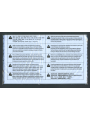
Important Warranty Information Regarding Television Format Viewing
Wide screen format LCD Displays (16:9, the aspect ratio of the screen width to height) are primarily designed to view wide screen format
full-motion video. The images displayed on them should primarily be in the wide screen 16:9 ratio format, or expanded to fill the screen
if your model offers this feature and the images are constantly moving. Displaying stationary graphics and images on screen, such as
the dark side-bars on nonexpanded standard format television video and programming, should be limited to no more than 5% of the total
television viewing per week.
Additionally, viewing other stationary images and text such as stock market reports, video game displays, station logos, web sites or
computer graphics and patterns, should be limited as described above for all televisions. Displaying stationary images that exceed the
above guidelines can cause uneven aging of LCD Displays that leave subtle, but permanent burned-in ghost images in the LCD picture. To
avoid this, vary the programming and images, and primarily display full screen moving images, not stationary patterns or dark bars.
On LCD models that offer picture sizing features, use these controls to view different formats as a full screen picture.
Be careful in the selection and duration of television formats used for viewing. Uneven LCD aging as a result of format selection and use,
as well as burned-in images, are not covered by your Samsung limited warranty.
U.S.A Only
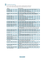
The product unit accompanying this user manual is licensed under certain intellectual property rights of certain third parties. In particular,
this product is licensed under the following US patents: 5,991,715, 5,740,317, 4,972,484, 5,214,678, 5,323,396, 5,539,829, 5,606,618,
5,530,655, 5,777,992, 6,289,308, 5,610,985, 5,481,643, 5,544,247, 5,960,037, 6,023,490, 5,878,080, and under US Published Patent
Application No. 2001-44713-A1.
This license is limited to private non-commercial use by end-user consumers for licensed contents. No rights are granted for commercial
use. The license does not cover any product unit other than this product unit and the license does not extend to any unlicensed product
unit or process conforming to ISO/IEC 11172-3 or ISO/IEC 13818-3 used or sold in combination with this product unit. The license only
covers the use of this product unit to encode and/or decode audio files conforming to the ISO/IEC 11172-3 or ISO/IEC 13818-3. No rights
are granted under this license for product features or functions that do not conform to the ISO/IEC 11172-3 or ISO/IEC 13818-3.
Other countries
The product unit accompanying this user manual is licensed under certain intellectual property rights of certain third parties. This license is
limited to private non-commercial use by end-user consumers for licensed contents. No rights are granted for commercial use. The license
does not cover any product unit other than this product unit and the license does not extend to any unlicensed product unit or process
conforming to ISO/IEC 11172-3 or ISO/IEC 13818-3 used or sold in combination with this product unit. The license only covers the use of
this product unit to encode and/or decode audio files conforming to the ISO/IEC 11172-3 or ISO/IEC 13818-3. No rights are granted under
this license for product features or functions that do not conform to the ISO/IEC 11172-3 or ISO/IEC 13818-3.
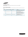
SAMSUNG ELECTRONICS NORTH AMERICAN LIMITED WARRANTY STATEMENT
Subject to the requirements, conditions, exclusions and limitations of the original Limited Warranty supplied with Samsung Electronics
(SAMSUNG) products, and the requirements, conditions, exclusions and limitations contained herein, SAMSUNG will additionally provide
Warranty Repair Service in the United States on SAMSUNG products purchased in Canada, and in Canada on SAMSUNG products purchased
in the United States, for the warranty period originally specified, and to the Original Purchaser only.
The above described warranty repairs must be performed by a SAMSUNG Authorized Service Center. Along with this Statement, the Original
Limited Warranty Statement and a dated Bill of Sale as Proof of Purchase must be presented to the Service Center. Transportation to and from
the Service Center is the responsibility of the purchaser.
Conditions covered are limited only to manufacturing defects in material or workmanship, and only those encountered in normal use of the
product.
Excluded, but not limited to, are any originally specified provisions for, in-home or on-site services, minimum or maximum repair times,
exchanges or replacements, accessories, options, upgrades, or consumables.
For the location of a SAMSUNG Authorized Service Center, please call toll-free:
In the United States : 1-800-SAMSUNG (1-800-726-7864)
In Canada : 1-800-SAMSUNG
° See the warranty card for more information on warranty terms.
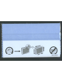
Precautions When Displaying a Still Image
A still image may cause permanent damage to the TV screen
• Do not display a still image on the LCD panel for more than 2 hours as it can cause screen image retention. This image retention is also
known as "screen burn". To avoid such image retention, reduce the degree of brightness and contrast of the screen when displaying a still
image.
•
Watching the LCD TV in 4:3 format for a long period of time may leave traces of borders displayed on the left, right and
center of the screen caused by the difference of light emission on the screen.
Playing a DVD or a game console may cause a similar effect to the screen.
Damages caused by the above effect are not covered by the Warranty.
• Displaying still images from Video games and PC for longer than a certain period of time may produce partial after-images.
To prevent this effect, reduce the ‘brightness’ and ‘contrast’ when displaying still images.
© 2008 Samsung Electronics Co., Ltd. All rights reserved.
English
Contents
GENERAL INFORMATION
CHANNEL CONTROL
List of Features............................................................................. 2
Accessories .................................................................................. 2
Viewing the Control Panel ........................................................... 3
Viewing the Connection Panel .................................................... 4
Remote Control ............................................................................ 6
Installing Batteries in the Remote Control .................................... 7
CONNECTIONS (LN26A450C1D, LN40A450C1D)
Connecting VHF and UHF Antennas............................................ 7
Connecting Cable TV ................................................................... 8
Connecting a DVD Player or Cable Box/Satellite receiver
(Set-Top Box) via HDMI................................................................ 9
Connecting a DVD Player or Cable Box/Satellite receiver
(Set-Top Box) via DVI ................................................................... 9
Connecting a DVD Player or Cable Box/Satellite receiver
(Set-Top Box) via Component cables ......................................... 10
Connecting a Camcorder .......................................................... 10
Connecting a VCR...................................................................... 11
Connecting a Digital Audio System ............................................ 12
Connecting an Amplier/DVD Home Theater ............................. 12
Connecting a PC ........................................................................ 13
CONNECTIONS (LN32A450C1D, LN37A450C1D)
Connecting VHF and UHF Antennas.......................................... 14
Connecting Cable TV ................................................................. 15
Connecting a DVD Player or Cable Box/Satellite receiver
(Set-Top Box) via HDMI.............................................................. 16
Connecting a DVD Player or Cable Box/Satellite receiver
(Set-Top Box) via DVI ................................................................. 16
Connecting a DVD Player or Cable Box/Satellite receiver
(Set-Top Box) via Component cables ......................................... 17
Connecting a Camcorder .......................................................... 17
Connecting a VCR...................................................................... 18
Connecting a Digital Audio System ............................................ 19
Connecting an Amplier/DVD Home Theater ............................. 19
Connecting a PC ........................................................................ 20
OPERATION
Turning the TV On and Off ......................................................... 21
Plug & Play Feature ................................................................... 21
Changing Channels .................................................................... 22
Adjusting the Volume.................................................................. 23
Viewing the Display .................................................................... 23
Viewing the Menus ..................................................................... 23
Using the TOOLS Button ............................................................ 24
Memorizing the Channels........................................................... 24
To Select the Source .................................................................. 26
To Edit the Input Source Name .................................................. 26
PICTURE CONTROL
Clearing Scrambled Channels - Digital ...................................... 39
Adding and Erasing Channels .................................................... 40
To Set-Up Your Favorite Channels ............................................. 41
Using the Channel Lists - Analog ............................................... 42
Viewing the Channel Lists .......................................................... 42
Labeling Channels...................................................................... 43
Fine Tuning Analog Channels .................................................... 44
Checking the Digital-Signal Strength.......................................... 44
PC DISPLAY
Using Your TV as a Computer (PC) Display............................... 45
Display Modes ............................................................................ 45
Setting up the TV with your PC .................................................. 46
TIME SETTING
Setting the Clock ........................................................................ 48
FUNCTION DESCRIPTION
Selecting a Menu Language....................................................... 51
Using the V-Chip ........................................................................ 52
Viewing Closed Captions (On-Screen Text Messages)
- Analog ...................................................................................... 59
Viewing Closed Captions (On-Screen Text Messages)
- Digital ....................................................................................... 60
Adjusting the TV On/Off Melody Sound...................................... 61
Setting the Entertainment mode ................................................. 61
Using the Energy Saving Feature .............................................. 62
Upgrading the Software.............................................................. 62
ABOUT ANYNET+
What is Anynet+? ....................................................................... 63
Connecting Anynet+ Devices ...................................................... 63
Setting Up Anynet+ ..................................................................... 64
Scanning and Switching between Anynet+ Devices ................... 64
Recording ................................................................................... 65
Listening through a Receiver (Home theater) ............................ 66
Troubleshooting for Anynet+ ....................................................... 66
APPENDIX
Troubleshooting .......................................................................... 67
Installing the Stand ..................................................................... 69
Disconnecting the Stand ............................................................ 69
Auto Wall-Mount Adjustment (Sold separately)
(LN32A450C1D, LN37A450C1D, LN40A450C1D) .................. 70
Wall Mount Kit Specications (VESA) ........................................ 71
Using the Anti-Theft Kensington Lock ........................................ 72
Specications ............................................................................. 73
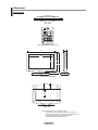
Dimensions................................................................................. 74
Changing the Picture Standard .................................................. 27
Customizing the Picture Settings ............................................... 27
Adjusting the Detailed Settings .................................................. 28
Conguring Picture Options ....................................................... 31
Resetting the Picture Settings to the Factory Defaults ............... 34
SOUND CONTROL
Changing the Sound Standard ................................................... 35
Customizing the Sound .............................................................. 35
Setting the TruSurround XT........................................................ 36
Choosing a Multi-Channel Sound (MTS) track - Digital ............. 36
Choosing a Multi-Channel Sound (MTS) track - Analog ............ 37
Automatic Volume Control .......................................................... 37
Setting the TV Speakers On/Off ................................................. 38
Connecting Headphones (Sold separately)................................ 38
English - 1
Symbol
Press
Note
One-Touch
Button
General Information
List of Features
Adjustable picture settings that can be stored in the TV’s memory.
Automatic timer to turn the TV on and off.
A special sleep timer.
Excellent Digital Interface & Networking :
With a built-in HD digital tuner, non-subscription HD broadcasts can be viewed with no Cable Box/Satellite receiver
(Set-Top Box) needed.
HDMI/DVI connection of your PC to this TV.
Excellent Picture Quality
- DNIe technology provides life-like clear images.
SRS TruSurround XT
- SRS TruSurround XT provides a virtual surround system.
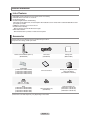
Accessories
Please make sure the following items are included with your LCD TV.
If any items are missing, contact your dealer.
Remote Control & Batteries (AAA x 2)
(BN59-00687A)
Cover-Bottom
(LN26A450C1D: BN63-04269A)
(LN32A450C1D: BN63-04269A)
(LN37A450C1D: BN63-04243A)
(LN40A450C1D: BN63-04243A)
Stand
(LN26A450C1D: BN96-06463E)
(LN32A450C1D: BN96-06464A)
(LN37A450C1D: BN96-07182A)
(LN40A450C1D: BN96-07182A)
Power Cord
(3903-000144)
Owner’s Instructions
Stand Screw (M4 X L16)
(6002-001294)
The items color and shape may vary depending on the model.
English - 2
Cleaning Cloth
(BN63-01798A)
Warranty Card / Registration Card /
Safety Guide Manual
(Not available in all locations)
Stand Screw (M4 X L14)
(LN32A450C1D : 6003-001334)
(LN37A450C1D : 6003-001334)
(LN40A450C1D : 6003-001334)
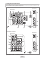
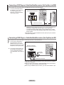
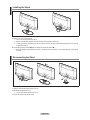
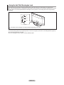
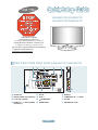
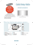
Viewing the Control Panel
Buttons on the Lower-Right Part of the Panel
The buttons on the lower-right panel control your TV’s basic features, including the on-screen menu.
To use the more advanced features, you must use the remote control.
Side Panel buttons
1
2
3
4
5
6
8
8
7
The product color and shape may vary depending on the model.
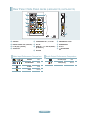
1 SOURCE
Toggles between all the available input sources
(TV, AV1, AV2, S-Video, Component1, Component2,
PC, HDMI1, HDMI2, HDMI3).
In the on-screen menu, use this button as you would
use the ENTER button on the remote control.
2 MENU
Press to see an on-screen menu of your TV’s features.
3 + VOL Press to increase or decrease the volume.
In the on-screen menu, use the + VOL - buttons as you
would use the and buttons on the remote control.
5
(POWER)
Press to turn the TV on and off.
6 REMOTE CONTROL SENSOR
Aim the remote control towards this spot on the TV.
7 POWER INDICATOR
Blinks and turns off when the power is on and
lights up in stand-by mode.
8 SPEAKERS
4 < CH >
Press to change channels.
In the on-screen menu, use the < CH > buttons as you
would use the and buttons on the remote control.
English - 3
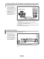
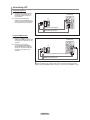
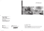
Viewing the Connection Panel
Use the connection panel jacks to connect A/V components that will be connected continuously, such as DVD players or a VCR.
For more information on connecting equipment, see pages 7~20.
LN26A450C1D, LN40A450C1D
[TV Side Panel]
[TV Rear Panel]
LN32A450C1D, LN37A450C1D
[TV Side Panel]
[TV Rear Panel]
The product color and shape may vary depending on the model.
English - 4
1 AUDIO OUT
Connects to the audio input jacks on your Amplifier/Home theater.
2 DIGITAL AUDIO OUT (OPTICAL)
Connects to a Digital Audio component.
3 PC IN [PC] / [AUDIO]
Connects to the video and audio output jacks on your PC.
4 HDMI IN 1, 2, 3 / DVI IN(HDMI2)[R-AUDIO-L] (LN26A450C1D, LN40A450C1D)
Connects to the HDMI jack of a device with an HDMI output.
Use the HDMI IN 2 jack for DVI connection to an external device.
Use a DVI to HDMI cable or DVI-HDMI adapter (DVI to HDMI) for video connection and the
DVI IN (HDMI2) [R-AUDIO-L] jacks for audio.
- No sound connection is needed for an HDMI to HDMI connection.
- When using an HDMI/DVI cable connection, you must use the HDMI IN 2 jack.
5 HDMI IN 1, 2, 3 / DVI IN(HDMI1)[R-AUDIO-L] (LN32A450C1D, LN37A450C1D)
Connects to the HDMI jack of a device with an HDMI output.
Use the HDMI IN 1 jack for DVI connection to an external device.
Use a DVI to HDMI cable or DVI-HDMI adapter (DVI to HDMI) for video connection and the
DVI IN (HDMI1) [R-AUDIO-L] jacks for audio.
- No sound connection is needed for an HDMI to HDMI connection.
- When using an HDMI/DVI cable connection, you must use the HDMI IN 1 jack.
6 ANT IN
Connects to an antenna or cable TV system.
7 AV IN 2
Video and audio inputs for external devices, such as a camcorder or VCR.
S-VIDEO
Connects an S-Video signal from a camcorder or VCR.
8
(HEADPHONE)
Connects a set of external headphones for private listening.
9 POWER INPUT
Connects the supplied power cord.
0 SERVICE
Connector for SERVICE only.
! COMPONENT IN 1, 2
The COMPONENT IN 1 jack is also used as the AV IN 1 jack.
- Connect the video cable to the COMPONENT IN 1 [Y/VIDEO] jack and the audio cable to the
COMPONENT IN 1 [R-AUDIO-L] jacks.
@ EX-LINK
- LN26A450C1D
Connector for SERVICE only.
- LN32A450C1D / LN37A450C1D / LN40A450C1D
Connect this to the jack on the optional wall mount bracket. This will allow you to adjust the TV viewing angle using
your remote control.
# KENSINGTON LOCK
The Kensington Lock (optional) is a device used to physically fix the system when used in a public place.
If you want to use a locking device, contact the dealer where you purchased the TV.
The location of the Kensington Lock may be different depending on its model.
English - 5
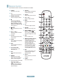
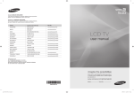
Remote Control
You can use the remote control up to a distance of about 23 feet from the TV.
1 POWER
Turns the TV on and off.
2 TV
Selects the TV mode directly.
3 NUMERIC BUTTONS
Press to change the channel.
4
Press to select additional
channels(digital and analog) being
broadcast by the same station.
For example, to select channel
“54-3”, press “54”, then press “ ”
and “3”.
5
(MUTE)
Press to temporarily cut off the
sound.
6 VOL / VOL
Press to increase or decrease
the volume.
7 CH LIST
Used to display Channel Lists on
the screen.
8 TOOLS
Use to quickly select frequently
used functions.
9 INFO
Press to display information on
the TV screen.
0 COLOR BUTTONS
Use these buttons in the
Channel list, etc.
$ SOURCE
Press to display and select the
available video sources.
% PRE CH
Tunes to the previous channel.
^ CH / CH
Press to change channels.
& MENU
Displays the main on-screen
menu.
* CC
Controls the caption decoder.
( RETURN
Returns to the previous menu.
) UP / DOWN / LEFT /
RIGHT / ENTER
Use to select on-screen menu
items and change menu values.
a EXIT
Press to exit the menu.
b DMA (Digital Media Adapter)
Use this when connecting a
SAMSUNG DMA device through
an HDMI interface and switching
to DMA mode.
For more information on the
operating procedures, refer to
the user manual of the DMA.
This button is available when
“Anynet+(HDMI-CEC)” is “On”
(see page 64)
! SRS
Selects SRS TruSurround XT
mode.
c MTS
Press to choose stereo, mono
or Separate Audio Program
(SAP broadcast).
@ E.MODE
Press to select the preset
display and sound modes for
sports, cinema and games.
d FAV.CH
Press to switch to your favorite
channels.
# Use these buttons in the DMA and
Anynet+ modes.
(
: This remote can be used
to control recording on Samsung
recorders with the Anynet+
feature)
e P.SIZE
Picture size selection.
The performance of the remote control may be affected by bright light.
English - 6
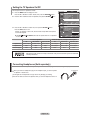
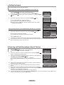
Installing Batteries in the Remote Control
1. Lift the cover at the back of the remote control upward as shown in the figure.
2. Install two AAA size batteries.
Make sure to match the "+" and "–" ends of the batteries with the diagram inside the compartment.
3. Replace the cover.
Remove the batteries and store them in a cool, dry place if you won’t be using the remote control for a
long time.
The remote control can be used up to about 23 feet from the TV.
(Assuming typical TV usage, the batteries should last for about one year.)
If the remote control doesn’t work, check the following:
1. Is the TV power on?
2. Are the plus and minus ends of the batteries reversed?
3. Are the batteries drained?
4. Is there a power outage or is the power cord unplugged?
5. Is there a special fluorescent light or neon sign nearby?
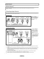
Connections (LN26A450C1D, LN40A450C1D)
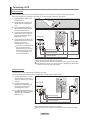
Connecting VHF and UHF Antennas
If your antenna has a set of leads that look like the diagram to the right, see "Antennas with
300 Flat Twin Leads" below.
If your antenna has one lead that looks like the diagram to the right, see "Antennas with 75
Round Leads".
If you have two antennas, see "Separate VHF and UHF Antennas".
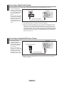
Antennas with 300 Flat Twin Leads
If you are using an off-air antenna (such as a roof antenna or "rabbit ears") that has 300 twin at leads, follow the directions
below.
1. Place the wires from the twin leads under the screws on a 300-75 adapter
(not supplied).
Use a screwdriver to tighten the screws.
2. Plug the adaptor into the ANT IN terminal on the back of the TV.
ANT IN
Antennas with 75 Round Leads
1. Plug the antenna lead into the ANT IN terminal on the back of the TV.
ANT IN
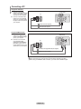
Separate VHF and UHF Antennas
If you have two separate antennas for your TV (one VHF and one UHF), you must combine the two antenna signals before
connecting the antennas to the TV. This procedure requires an optional combiner-adaptor (available at most electronics shops).
1. Connect both antenna leads to the combiner.
UHF
VHF
2. Plug the combiner into the ANT IN terminal on the bottom of the rear panel.
ANT IN
UHF
VHF
English - 7
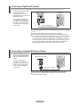
Connecting Cable TV
To connect to a cable TV system, follow the instructions below.
Cable without a Cable Box
1. Plug the incoming cable into the ANT IN terminal on the back of the TV.
ANT IN
Because this TV is cable-ready, you do not need a cable box to view unscrambled cable channels.
Connecting to a Cable Box that Descrambles All Channels
1. Find the cable that is connected to the ANT OUT terminal on your cable box.
ANT IN
This terminal might be labeled "ANT OUT", "VHF OUT" or simply, "OUT".
ANT OUT
2. Connect the other end of this cable to the ANT IN terminal on the back of the TV.
ANT IN
Connecting to a Cable Box that Descrambles Some Channels
If your cable box descrambles only some channels (such as premium channels), follow the instructions below. You will need a twoway splitter, an RF (A/B) switch and four lengths of RF cable. (These items are available at most electronics stores.)
1. Find and disconnect the cable that is
connected to the ANT IN terminal on your
cable box.
ANT IN
This terminal might be labeled "ANT IN",
"VHF IN" or simply, "IN".
2. Connect this cable to a two-way splitter.
Incoming
cable
3. Connect an RF cable between the OUTPUT
terminal on the splitter and the IN terminal
on the cable box.
Incoming
cable
Splitter
Splitter
Cable Box
4. Connect an RF cable between the
ANT OUT terminal on the cable box and
the B–IN terminal on the RF(A/B) switch.
Incoming
cable
Splitter
RF (A/B)
Switch
Cable Box
5. Connect another cable between the other
OUT terminal on the splitter and the A–IN
terminal on the RF (A/B) switch.
Incoming
cable
Splitter
Cable Box
6. Connect the last RF cable between the
OUT terminal on the RF (A/B) switch and
the ANT IN terminal on the rear of the TV.
RF (A/B)
Switch
ANT IN
Incoming
cable
TV Rear
Splitter
Cable Box
RF (A/B)
Switch
After you have made this connection, set the A/B switch to the "A" position for normal viewing. Set the A/B switch to the "B" position to
view scrambled channels. (When you set the A/B switch to "B", you will need to tune your TV to the cable box’s output channel, which is
usually channel 3 or 4.)
English - 8
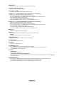
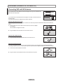
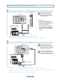
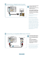
Connecting a DVD Player or Cable Box/Satellite receiver (Set-Top Box) via HDMI
This connection can only be made if there is an HDMI Output connector on the external device.
1. Connect an HDMI Cable
between the HDMI IN (1, 2
or 3) jack on the TV and the
HDMI jack on the DVD Player
or Cable Box/Satellite receiver
(Set-Top Box).
DVD Player or Cable Box/Satellite receiver
(Set-Top Box) Rear Panel
TV Side Panel
TV Rear Panel
HDMI Cable (Not supplied)
or
What is HDMI?
• HDMI(High-Definition Multimedia Interface), is an interface that enables the
transmission of digital audio and video signals using a single cable.
• The difference between HDMI and DVI is that the HDMI device is smaller in
size and has the HDCP (High Bandwidth Digital Copy Protection) coding feature
installed.
Each DVD Player or Cable Box/Satellite receiver (Set-Top Box) has a different back
panel configuration.
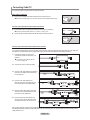
Connecting a DVD Player or Cable Box/Satellite receiver (Set-Top Box) via DVI
This connection can only be made if there is a DVI Output connector on the external device.
1. Connect a DVI to HDMI Cable
or DVI-HDMI Adapter between
the HDMI IN 2 jack on the TV
and the DVI jack on the DVD
Player or Cable Box/Satellite
receiver (Set-Top Box).
TV Rear Panel
DVD Player or Cable Box/
Satellite receiver (Set-Top Box)
2. Connect Audio Cables
between the DVI IN (HDMI 2)
[R-AUDIO-L] jack on the TV
and the DVD Player or Cable
Box/Satellite receiver (Set-Top
Box).
2 Audio Cable
(Not supplied)
1 DVI to HDMI Cable (Not supplied)
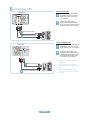
Each DVD Player or Cable Box/Satellite receiver (Set-Top Box) has a different back
panel configuration.
When connecting a DVD Player or Cable Box/Satellite receiver (Set-Top Box), match
the color of the connection terminal to the cable.
When using an HDMI/DVI cable connection, you must use the HDMI IN 2 jack.
English - 9
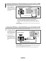
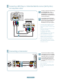
Connecting a DVD Player or Cable Box/Satellite receiver (Set-Top Box) via Component cables
The rear panel jacks on your TV make it easy to connect a DVD Player or Cable Box/Satellite receiver (Set-Top Box) to your TV.
1. Connect a Component Cable
TV Rear Panel
between the COMPONENT
IN (1 or 2) [Y, PB, PR] jacks on
the TV and the COMPONENT
DVD Player or Cable Box /
Satellite receiver (Set-Top Box)
[Y, PB, PR] jacks on the DVD
Player or Cable Box/Satellite
receiver (Set-Top Box).
2. Connect Audio Cables between
the COMPONENT IN(1 or 2)
[R-AUDIO-L] jacks on the TV
and the AUDIO OUT jacks
on the DVD Player or Cable
Box/Satellite receiver (Set-Top
Box).
2
Audio Cable (Not supplied)
1 Component Cable (Not supplied)
Component video separates the video into Y (Luminance (brightness)), Pb (Blue) and
Pr (Red) for enhanced video quality.
Be sure to match the component video and audio connections.
For example, if connecting a Component video cable to COMPONENT IN 1, connect the
audio cable to COMPONENT IN 1 also.
Each DVD Player or Cable Box/Satellite receiver (Set-Top Box) has a different back panel
configuration.
When connecting a DVD Player or Cable Box/Satellite receiver (Set-Top Box), match the
color of the connection terminal to the cable.
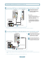
Connecting a Camcorder
The side panel jacks on your TV make it easy to connect a camcorder to your TV.
They allow you to view the camcorder tapes without using a VCR.
1. Connect a Video Cable
(or S-Video Cable) between
the AV IN 2 [VIDEO] (or
S-VIDEO) jack on the TV
and the VIDEO OUT jack on
the camcorder.
2. Connect Audio Cables
between the AV IN 2
[R-AUDIO-L] jacks on the TV
and the AUDIO OUT jacks
on the camcorder.
TV Side Panel
1 S-Video Cable (Not supplied)
or
Camcorder
1 Video Cable (Not supplied)
2 Audio Cable (Not supplied)
Each Camcorder has a different back panel configuration.
When connecting a Camcorder, match the color of the connection terminal to the cable.
English - 10
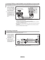
Connecting a VCR
Video Connection
These instructions assume that you have already connected your TV to an antenna or a cable TV system (according to the
instructions on pages 7~8). Skip step 1 if you have not yet connected to an antenna or a cable system.
1. Unplug the cable or antenna
from the back of the TV.
ANT IN
2. Connect the cable or antenna to
the ANT IN terminal on the back
of the VCR.
3.
Connect an RF Cable between
the ANT OUT terminal on the
VCR and the ANT IN terminal
on the TV.
4. Connect a Video Cable
between the VIDEO OUT jack
on the VCR and the AV IN 1
[Y/VIDEO] or AV IN 2 [VIDEO]
jack on the TV.
TV Side Panel
TV Rear Panel
VCR Rear Panel
5. Connect Audio Cables
between the AUDIO OUT
jacks on the VCR and the AV
IN 1 (or AV IN 2) [R-AUDIO-L]
jacks on the TV.
If you have a “mono”
(non-stereo) VCR, use a
Y-connector (not supplied)
to hook up to the right and
left audio input jacks of the
TV. If your VCRis stereo,
you mustm connect two
cables.
5 Audio Cable (Not supplied)
4 Video Cable (Not supplied)
3 RF Cable (Not supplied)
Follow the instructions in “Viewing a VCR or Camcorder Tape” to view your VCR tape.
Each VCR has a different back panel configuration.
When connecting a VCR, match the color of the connection terminal to the cable.
When connecting to AV IN 1, the color of the AV IN 1 [Y/VIDEO] jack (Green) does not
match the color of the video cable (Yellow).
S-Video Connection
Your Samsung TV can be connected to an S-Video jack on a VCR.
(This connection delivers a better picture when compared to the regular Video connection above.)
1. To begin, follow steps 1–3
in the previous section to
connect the antenna or
cable to your VCR and your
TV.
TV Rear Panel
TV Side Panel
VCR Rear Panel
2. Connect an S-Video Cable
between the S-VIDEO OUT
jack on the VCR and the
AV IN 2 [S-VIDEO] jack on
the TV.
3. Connect Audio Cables
between the AUDIO OUT
jacks on the VCR and the
AV IN 2 [R-AUDIO-L] jacks
on the TV.
1 RF Cable (Not supplied)
2 S-Video Cable (Not supplied)
3 Audio Cable (Not supplied)
An S-Video cable may be included with a VCR. (If not, check your local electronics store.)
Each VCR has a different back panel configuration.
When connecting a VCR, match the color of the connection terminal to the cable.
English - 11
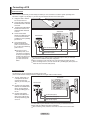
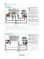
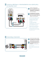
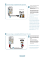
Connecting a Digital Audio System
The rear panel jacks on your TV make it easy to connect a Digital Audio System (Home theater/Receiver) to your TV.
1. Connect an Optical Cable
between the “DIGITAL AUDIO
OUT (OPTICAL)” jacks on the
TV and the Digital Audio Input
jacks on the Digital Audio
System.
When a Digital Audio System
is connected to the “DIGITAL
AUDIO OUT (OPTICAL)” jack:
Decrease the volume of the
TV and adjust the volume
level with the system’s volume
control.
Digital Audio System
TV Rear Panel
Optical Cable (Not supplied)
5.1CH audio is possible when the TV is connected to an external device supporting 5.1CH.
Each Digital Audio System has a different back panel configuration.
When the receiver (home theater) is set to On, you can hear sound output from the TV’s
Optical jack. When the TV is displaying a DTV(air) signal, the TV will send out 5.1 channel sound to the Home theater receiver. When the source is a digital component such as
a DVD and is connected to the TV via HDMI, only 2 channel sound will be heard from the
Home Theater receiver. If you want to hear 5.1 channel audio, connect the DIGITAL AUDIO
OUT (OPTICAL) jack on the DVD player or Cable/Satellite Box directly to an Amplifier or
Home Theater, not the TV.
Connecting an Amplier/DVD Home Theater
1. Connect Audio Cables
between the AUDIO OUT
[R-AUDIO-L] jacks on the TV
and AUDIO IN [R-AUDIO-L]
jacks on the Amplifier/DVD
Home Theater.
When an audio amplifier is
connected to the "AUDIO OUT
[R-AUDIO-L]" jacks: Decrease
the volume of the TV and
adjust the volume level with
the Amplifier’s volume control.
TV Rear Panel
Amplier/DVD Home Theater
Audio Cable (Not supplied)
Each Amplifier/DVD Home Theater has a different back panel configuration.
When connecting an Amplifier/DVD Home Theater, match the color of the connection
terminal to the cable.
English - 12
Connecting a PC
Using the D-Sub Cable
1. Connect a D-Sub Cable
between PC IN [PC] connector
on the TV and the PC output
connector on your computer.
TV Rear Panel
PC
2. Connect a PC Audio Cable
between the PC IN [AUDIO]
jack on the TV and the Audio
Out jack of the sound card on
your computer.
2 PC Audio Cable (Not supplied)
1 D-Sub Cable (Not supplied)
Using the HDMI/DVI Cable
1. Connect a HDMI/DVI cable
between the HDMI IN 2 jack
on the TV and the PC output
jack on your computer.
2. Connect a 3.5 mm Stereo
mini-plug/2RCA Cable
between the DVI IN(HDMI2)
[R-AUDIO-L] jack on the TV
and the Audio Out jack of the
sound card on your computer.
TV Rear Panel
PC
2 3.5 mm Stereo mini-plug/2RCA Cable (Not supplied)
1 HDMI/DVI Cable (Not supplied)
Each PC has a different back panel configuration.
When connecting a PC, match the color of the connection terminal to the cable.
When using an HDMI/DVI cable connection, you must use the HDMI IN 2 jack.
English - 13
Connections (LN32A450C1D, LN37A450C1D)
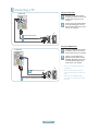
Connecting VHF and UHF Antennas
If your antenna has a set of leads that look like the diagram to the right, see "Antennas with
300 Flat Twin Leads" below.
If your antenna has one lead that looks like the diagram to the right, see "Antennas with 75
Round Leads".
If you have two antennas, see "Separate VHF and UHF Antennas".
Antennas with 300 Flat Twin Leads
If you are using an off-air antenna (such as a roof antenna or "rabbit ears") that has 300 twin at leads, follow the directions
below.
1. Place the wires from the twin leads under the screws on a 300-75 adapter
(not supplied).
Use a screwdriver to tighten the screws.
2. Plug the adaptor into the ANT IN terminal on the back of the TV.
ANT IN
Antennas with 75 Round Leads
1. Plug the antenna lead into the ANT IN terminal on the back of the TV.
ANT IN
Separate VHF and UHF Antennas
If you have two separate antennas for your TV (one VHF and one UHF), you must combine the two antenna signals before
connecting the antennas to the TV. This procedure requires an optional combiner-adaptor (available at most electronics shops).
1. Connect both antenna leads to the combiner.
UHF
VHF
2. Plug the combiner into the ANT IN terminal on the bottom of the rear panel.
ANT IN
UHF
VHF
English - 14
Connecting Cable TV
To connect to a cable TV system, follow the instructions below.
Cable without a Cable Box
1. Plug the incoming cable into the ANT IN terminal on the back of the TV.
ANT IN
Because this TV is cable-ready, you do not need a cable box to view unscrambled cable channels.
Connecting to a Cable Box that Descrambles All Channels
1. Find the cable that is connected to the ANT OUT terminal on your cable box.
ANT IN
This terminal might be labeled "ANT OUT", "VHF OUT" or simply, "OUT".
ANT OUT
2. Connect the other end of this cable to the ANT IN terminal on the back of the TV.
ANT IN
Connecting to a Cable Box that Descrambles Some Channels
If your cable box descrambles only some channels (such as premium channels), follow the instructions below. You will need a twoway splitter, an RF (A/B) switch and four lengths of RF cable. (These items are available at most electronics stores.)
1. Find and disconnect the cable that is
connected to the ANT IN terminal on your
cable box.
ANT IN
This terminal might be labeled "ANT IN",
"VHF IN" or simply, "IN".
2. Connect this cable to a two-way splitter.
Incoming
cable
3. Connect an RF cable between the OUTPUT
terminal on the splitter and the IN terminal
on the cable box.
Incoming
cable
Splitter
Splitter
Cable Box
4. Connect an RF cable between the
ANT OUT terminal on the cable box and
the B–IN terminal on the RF(A/B) switch.
Incoming
cable
Splitter
RF (A/B)
Switch
Cable Box
5. Connect another cable between the other
OUT terminal on the splitter and the A–IN
terminal on the RF (A/B) switch.
Incoming
cable
Splitter
Cable Box
6. Connect the last RF cable between the
OUT terminal on the RF (A/B) switch and
the ANT IN terminal on the rear of the TV.
RF (A/B)
Switch
ANT IN
Incoming
cable
TV Rear
Splitter
Cable Box
RF (A/B)
Switch
After you have made this connection, set the A/B switch to the "A" position for normal viewing. Set the A/B switch to the "B" position to
view scrambled channels. (When you set the A/B switch to "B", you will need to tune your TV to the cable box’s output channel, which is
usually channel 3 or 4.)
English - 15
Connecting a DVD Player or Cable Box/Satellite receiver (Set-Top Box) via HDMI
This connection can only be made if there is an HDMI Output connector on the external device.
1. Connect an HDMI Cable between
the HDMI IN (1, 2 or 3) jack on the
TV and the HDMI jack on the
DVD Player or Cable Box/Satellite
receiver (Set-Top Box).
TV Rear Panel
DVD Player or Cable Box/Satellite
receiver (Set-Top Box) Rear Panel
TV Side Panel
or
HDMI Cable (Not supplied)
What is HDMI?
• HDMI(High-Definition Multimedia Interface), is an interface that enables the
transmission of digital audio and video signals using a single cable.
• The difference between HDMI and DVI is that the HDMI device is smaller
in size and has the HDCP (High Bandwidth Digital Copy Protection) coding
feature installed.
Each DVD Player or Cable Box/Satellite receiver (Set-Top Box) has a different
back panel configuration.
Connecting a DVD Player or Cable Box/Satellite receiver (Set-Top Box) via DVI
This connection can only be made if there is a DVI Output connector on the external device.
1. Connect a DVI to HDMI Cable or
DVI-HDMI Adapter between the
HDMI IN 1 jack on the TV and the
DVI jack on the DVD Player or Cable
Box/Satellite receiver (Set-Top Box).
TV Rear Panel
DVD Player or Cable Box/
Satellite receiver (Set-Top Box)
2. Connect Audio Cables between the
DVI IN (HDMI 1) [R-AUDIO-L] jack
on the TV and the DVD Player or
Cable Box/Satellite receiver (Set-Top
Box).
2 Audio Cable
(Not supplied)
1 DVI to HDMI Cable (Not supplied)
Each DVD Player or Cable Box/Satellite receiver (Set-Top Box) has a different
back panel configuration.
When connecting a DVD Player or Cable Box/Satellite receiver (Set-Top Box),
match the color of the connection terminal to the cable.
When using an HDMI/DVI cable connection, you must use the HDMI IN 1 jack.
English - 16
Connecting a DVD Player or Cable Box/Satellite receiver (Set-Top Box) via Component cables
The rear panel jacks on your TV make it easy to connect a DVD Player or Cable Box/Satellite receiver (Set-Top Box) to your TV.
1. Connect a Component Cable
TV Rear Panel
between the COMPONENT IN
(1 or 2) [Y, PB, PR] jacks on the TV
and the COMPONENT [Y, PB, PR]
DVD Player or Cable Box /
jacks on the DVD Player or Cable
Satellite receiver (Set-Top Box)
Box/Satellite receiver (Set-Top Box).
2. Connect Audio Cables between the
COMPONENT IN(1 or 2)
[R-AUDIO-L] jacks on the TV
and the AUDIO OUT jacks on the
DVD Player or Cable Box/Satellite
receiver (Set-Top Box).
2
Audio Cable (Not supplied)
1 Component Cable (Not supplied)
Component video separates the video into Y (Luminance (brightness)), Pb (Blue)
and Pr (Red) for enhanced video quality. Be sure to match the component video and
audio connections.
For example, if connecting a Component video cable to COMPONENT IN 1,
connect the audio cable to COMPONENT IN 1 also.
Each DVD Player or Cable Box/Satellite receiver (Set-Top Box) has a different back
panel configuration.
When connecting a DVD Player or Cable Box/Satellite receiver (Set-Top Box), match the
color of the connection terminal to the cable.
Connecting a Camcorder
The side panel jacks on your TV make it easy to connect a camcorder to your TV.
They allow you to view the camcorder tapes without using a VCR.
1. Connect a Video Cable
(or S-Video Cable) between the
AV IN 2 [VIDEO] (or S-VIDEO)
jack on the TV and the VIDEO
OUT jack on the camcorder.
2. Connect Audio Cables between
the AV IN 2 [R-AUDIO-L] jacks
on the TV and the AUDIO OUT
jacks on the camcorder.
TV Side Panel
1 S-Video Cable (Not supplied)
or
Camcorder
1 Video Cable (Not supplied)
2 Audio Cable (Not supplied)
Each Camcorder has a different back panel configuration.
When connecting a Camcorder, match the color of the connection terminal to the
cable.
English - 17
Connecting a VCR
Video Connection
These instructions assume that you have already connected your TV to an antenna or a cable TV system (according to the
instructions on pages 14~15). Skip step 1 if you have not yet connected to an antenna or a cable system.
1. Unplug the cable or antenna from
the back of the TV.
ANT IN
2. Connect the cable or antenna to the
ANT IN terminal on the back of the
VCR.
3. Connect an RF Cable between the
ANT OUT terminal on the VCR and
the ANT IN terminal on the TV.
4. Connect a Video Cable between the
VIDEO OUT jack on the VCR and
the AV IN 1 [Y/VIDEO] or AV IN 2
[VIDEO] jack on the TV.
TV Rear Panel
TV Side Panel
VCR Rear Panel
5. Connect Audio Cables between the
AUDIO OUT jacks on the VCR and
the AV IN 1 (or AV IN 2)
[R-AUDIO-L] jacks on the TV.
If you have a “mono”(non-stereo)
VCR, use aY-connector (not
supplied) to hook up to the right
and left audio input jacks of the
TV. If your VCR is stereo, you
must connect two cables.
5 Audio Cable (Not supplied)
4 Video Cable (Not supplied)
3 RF Cable (Not supplied)
Follow the instructions in “Viewing a VCR or Camcorder Tape” to view your VCR tape.
Each VCR has a different back panel configuration.
When connecting a VCR, match the color of the connection terminal to the cable.
When connecting to AV IN 1, the color of the AV IN 1 [Y/VIDEO] jack (Green) does
not match the color of the video cable (Yellow).
S-Video Connection
Your Samsung TV can be connected to an S-Video jack on a VCR.
(This connection delivers a better picture when compared to the regular Video connection above.)
TV Rear Panel
1. To begin, follow steps 1–3 in the
previous section to connect the
antenna or cable to your VCR and
your TV.
2. Connect an S-Video Cable
between the S-VIDEO OUT jack
on the VCR and the AV IN 2
[S-VIDEO] jack on the TV.
3. Connect Audio Cables between
the AUDIO OUT jacks on the VCR
and the AV IN 2 [R-AUDIO-L]
jacks on the TV.
TV Side Panel
VCR Rear Panel
1 RF Cable (Not supplied)
2 S-Video Cable (Not supplied)
3 Audio Cable (Not supplied)
An S-Video cable may be included with a VCR. (If not, check your local electronics store.)
Each VCR has a different back panel configuration.
When connecting a VCR, match the color of the connection terminal to the cable.
English - 18
Connecting a Digital Audio System
The rear panel jacks on your TV make it easy to connect a Digital Audio System (Home theater/Receiver) to your TV.
1. Connect an Optical Cable between
the “DIGITAL AUDIO OUT
(OPTICAL)” jacks on the TV and
the Digital Audio Input jacks on the
Digital Audio System.
When a Digital Audio System is
connected to the “DIGITAL AUDIO
OUT (OPTICAL)” jack: Decrease
the volume of the TV and adjust
the volume level with the system’s
volume control.
Digital Audio System
TV Rear Panel
Optical Cable (Not supplied)
5.1CH audio is possible when the TV is connected to an external device supporting
5.1CH.
Each Digital Audio System has a different back panel configuration.
When the receiver (home theater) is set to On, you can hear sound output from
the TV’s Optical jack. When the TV is displaying a DTV(air) signal, the TV will send
out 5.1 channel sound to the Home theater receiver. When the source is a digital
component such as a DVD and is connected to the TV via HDMI, only 2 channel
sound will be heard from the Home Theater receiver. If you want to hear 5.1 channel
audio, connect the DIGITAL AUDIO OUT (OPTICAL) jack on the DVD player or
Cable/Satellite Box directly to an Amplifier or Home Theater, not the TV.
Connecting an Amplier/DVD Home Theater
1. Connect Audio Cables between the
AUDIO OUT [R-AUDIO-L] jacks on
the TV and AUDIO IN [R-AUDIO-L]
jacks on the Amplifier/DVD Home
Theater.
TV Rear Panel
Amplier/DVD Home Theater
When an audio amplifier is
connected to the "AUDIO OUT
[R-AUDIO-L]" jacks: Decrease the
volume of the TV and adjust the
volume level with the Amplifier’s
volume control.
Audio Cable (Not supplied)
Each Amplifier/DVD Home Theater has a different back panel configuration.
When connecting an Amplifier/DVD Home Theater, match the color of the
connection terminal to the cable.
English - 19
Connecting a PC
Using the D-Sub Cable
1. Connect a D-Sub Cable between
PC IN [PC] connector on the TV
and the PC output connector on
your computer.
2. Connect a PC Audio Cable
between the PC IN [AUDIO] jack
on the TV and the Audio Out jack of
the sound card on your computer.
TV Rear Panel
PC
2 PC Audio Cable (Not supplied)
1 D-Sub Cable (Not supplied)
Using the HDMI/DVI Cable
1. Connect a HDMI/DVI cable
between the HDMI IN 1 jack on the
TV and the PC output jack on your
computer.
2. Connect a 3.5 mm Stereo
mini-plug/2RCA Cable between
the DVI IN(HDMI1) [R-AUDIO-L]
jack on the TV and the Audio Out
jack of the sound card on your
computer.
TV Rear Panel
PC
2 3.5 mm Stereo mini-plug/2RCA Cable (Not supplied)
1 HDMI/DVI Cable (Not supplied)
Each PC has a different back panel configuration.
When connecting a PC, match the color of the connection terminal to the cable.
When using an HDMI/DVI cable connection, you must use the HDMI IN 1 jack.
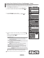
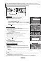
English - 20
Operation
Turning the TV On and Off
Press the POWER
button on the remote control.
You can also use the POWER
button on the TV.
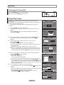
Plug & Play Feature
When the TV is initially powered on, basic settings proceed automatically and
subsequently.
The Screen Saver is activated if there is no remote control key input for longer than 1
minute while “Plug & Play” is running.
The Screen Saver is activated if there is no operating signal for longer than 15
minutes.
Plug & Play
Menu Language, Store Demo,
Channels and Time will be set.
Start
Enter
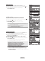
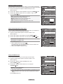
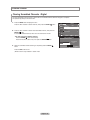
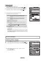
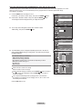
1. Press the POWER button on the remote control.
The message “Menu Language, Store Demo, Channels and Time will be set.” is
displayed.
button, then “Select the language of the OSD” menu
Press the ENTER
is automatically displayed.
Plug & Play
Select the language of the OSD.
Language
:
English
Español
Français
Move
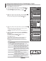
2. Press the or button to select language, then press the ENTER
button.
The message “Select ‘Home Use’ when installing this TV in your home.” is
displayed.
Plug & Play
Select ‘Home Use’ when installing this TV in your
home.
Store Demo
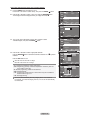
3. Press the or button to select “Store Demo” or “Home Use”, then
press the ENTER
button.
The message “Select the antennas to memorize.” is displayed.
Move
We recommend setting the TV to “Home Use” mode for the best picture in your
home environment.
“Store Demo” mode is only intended for use in retail environments.
If the unit is accidentally set to “Store Demo” mode and you want to return to
“Home Use” (Standard): Press the Volume button on the TV. When the volume
OSD is displayed, press and hold the MENU button on the TV for 5 seconds.
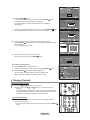
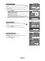
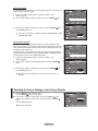
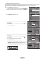
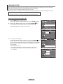
4. Press the or button to memorize the channels of the selected connection.
button to select “Start”.
Press the ENTER
Air: “Air” antenna signal.
Cable: “Cable” antenna signal.
Auto: “Air” and “Cable” antenna signals.
In Cable mode, you can select the correct signal source among STD, HRC, and
button. If
IRC by pressing the , , or button, then press the ENTER
you have Digital cable, select the cable system signal source for both Analog and
Digital. Contact your local cable company to identify the type of cable system that
exists in your particular area.
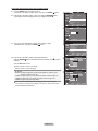
5. The TV will begin memorizing all of the available channels.
To stop the search before it has finished, press the ENTER
selected.
button with “Stop”
After all the available channels are stored, it starts to remove scrambled channels
(see page 39). The Auto program menu then reappears.
Press the ENTER
button when channel memorization is complete.
The message “Set the Clock Mode.” is displayed.
Enter
Home Use
Enter
Plug & Play
Select the antennas to memorize.
Air
Start
Cable
Start
Auto
Start
Move
Enter
Skip
Plug & Play
Selects a cable signal type for your location.
Analog
Start
STD
HRC
IRC
Digital
STD
HRC
IRC
Move
Enter
PlugProgram
& Play
Auto
Auto Program in Progress.
DTV Air : 02
Air : 11
DTV Cable : 23 Cable : 21
Skip
Cable 50
50 %
Stop
Enter
Skip
PlugProgram
& Play
Auto
Removing scrambled channel.
DTV Cable 41
77 %
Stop
Enter
English - 21
Skip
Auto
PlugProgram
& Play
Auto Program is completed.
75 Channels are memorized.
DTV Air : 24
Air : 1
DTV Cable : 17 Cable : 33
OK
Enter
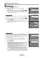
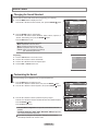
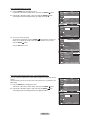
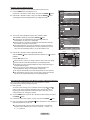
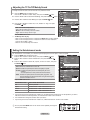
6. Press the ENTER
button.
Press the or button to select “Auto”, then Press the ENTER
The message “Set to daylight saving time.” is displayed.
Skip
Plug & Play
button.
Set the Clock Mode.
Clock Mode
If you select “Manual”, “Enter the current date and time.” is displayed.
(See page 48)
7. Press the or button to select “Off” or “On”, then press the ENTER
The message “Select the time zone in which you live.” is displayed.
:
Auto
Manual
Move
Enter
button.
Skip
Plug & Play
Set to daylight saving time.
DST
:
Off
On
Move
8. Press the or button to highlight the time zone for your local area.
button. If you have received a digital signal, the time will be
Press the ENTER
set automatically.
If not, see page 48 to set the clock.
Enter
Skip
Plug & Play
Select the time zone in which you live.
Newfoundland
Atlantic
Eastern
Central
Mountain
Pacific
Alaska
Hawaii
Move
9. The message “Enjoy your watching.” is displayed.
When you have finished, press the ENTER
button.
Enter
Skip
Plug & Play
Enjoy your watching.
OK
Enter
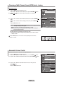
If you want to reset this feature...
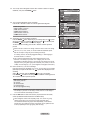
1. Press the MENU button to display the menu.
Press the or button to select "Setup", then press the ENTER
TV
button.
button again to select “Plug & Play”.
2. Press the ENTER
For further details on setting up options, refer to the pages 21~22.
The “Plug & Play” feature is only available in the TV mode.
Setup
Plug & Play
Language
Time
V-Chip
Caption
External Settings
Entertainment
More
Move
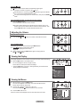
Changing Channels
Using the Channel Buttons
1. Press the CH
or CH
button to change channels.
When you press the CH or CH button, the TV changes channels in
sequence.
You will see all the channels that the TV has memorized. (The TV must have
memorized at least three channels). You will not see channels that were either
erased or not memorized. See page 24 to memorize channels.
Using the Number Buttons
1. Press the number buttons to go directly to a channel. For example, to select
channel 27, press 2, then 7.
For quick channel change, press the number buttons, then press the ENTER
button.
English - 22
: English
: Off
Enter
Return
Using the
The
Button
button is used to select stations that broadcast a digital signal.
1. For example, for Channel 7-1, press 7, then
, then 1.
HD indicates the TV is receiving a Digital High Definition signal. SD indicates
the TV is receiving a Standard Definition signal.
For quick channel change, press the number buttons, then press the ENTER
button.
Using the PRE CH Button to select the Previous Channel
1. Press the PRE CH button.
The TV will switch to the last channel viewed.
To quickly switch between two channels that are far apart, tune to one
channel, then use the number button to select the second channel. Then
use the PRE CH button to quickly alternate between them.
Adjusting the Volume
Using the Volume Buttons
1. Press the VOL
or VOL
button to increase or decrease the volume.
Using the MUTE button
At any time, you can cut off the sound using the MUTE button.
1. Press MUTE button and the sound cuts off.
" is displayed on the screen.
"
2. To turn mute off, press the MUTE button again or simply press the
VOL or VOL button.
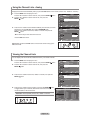
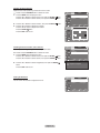
Viewing the Display
The display identies the current channel and the status of certain audio-video settings.
1. Press the INFO button on the remote control.
The TV will display the channel, the type of sound,
and the status of certain picture and sound settings.
° Press the INFO button once more or wait approximately 10 seconds and the
display disappears automatically.
Air 7
Mono
Picture Mode
Sound Mode
MTS
V-Chip
Caption
5 : 54 pm
: Standard
: Custom
: Stereo
: Off
: Off
Viewing the Menus
1. With the power on, press the MENU button.
The main menu appears on the screen. The menu’s left side has icons:
Picture, Sound, Channel, Setup, Input.
2. Press the or button to select one of the icons.
button to access the icon’s sub-menu.
Then press the ENTER
3. Press the EXIT button to exit.
The on-screen menus disappear from the screen after about one minute.
TV
Picture
Mode
Backlight
Contrast
Brightness
Sharpness
Color
Tint
G 50
More
Move
English - 23
: Standard
Enter
7
95
45
50
50
R 50
Exit
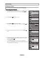
Using the TOOLS Button
You can use the TOOLS button to select your frequently used functions quickly and
easily. The “Tools” menu changes depending on which external input mode you are
viewing.
1. Press the TOOLS button.
The “Tools” menu will appear.
Tools
2. Press the or button to select a menu.
Anynet+(HDMI-CEC)
Picture Mode
:
Sound Mode
:
Sleep Timer
:
Add to Favorite
Switch to Air
buttons to display, change, or use the selected
3. Press the ////ENTER
items.For a more detailed description of each function, refer to the corresponding
page.
• Anynet+(HDMI-CEC), see page 64
• Picture Mode, see page 27
• Sound Mode, see page 35
• Sleep Timer, see page 50
• Add to Favorite, see page 41
• Switch to Air, see page 24
• Auto Adjustment, see page 46
Move
Enter
Standard
Custom
Off
Exit
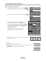
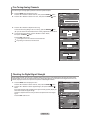
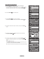
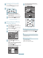
Memorizing the Channels
Your TV can memorize and store all of the available channels for both "off-air" (Air) and "Cable" channels. After the available
channels are memorized, use the CH or CH button to scan through the channels. This eliminates the need to change channels
by entering the channel digits. There are three steps for memorizing channels: selecting a broadcast source, memorizing the
channels (automatic) and adding or deleting channels (Channel Lists).
Selecting the Video Signal-source
Before your television can begin memorizing the available channels, you must specify the
type of signal source that is connected to the TV (i.e. an Air or a Cable system).
1. Press the MENU button to display the menu.
Press the or button to select "Channel", then press the ENTER
TV
button.
2. Press the ENTER
button to select “Antenna”.
Press the or button to select “Air” or “Cable”, then press the ENTER
Channel
Antenna
: Air
Auto Program
Clear Scrambled Channel
Channel List
Name
Fine Tune
Signal Strength
Move
button.
Press the EXIT button to exit.
TV
Enter
Return
Channel
Antenna
: Air
Air
Auto Program
Cable
Clear Scrambled Channel
Channel List
Name
Fine Tune
Signal Strength
Move
Enter
Return
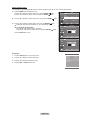
Tools
Easy Setting
1.
Press the TOOLS button on the remote control.
2.
Press the or button to select “Switch to Air” (or “Switch to Cable”), then press
the ENTER
button.
Anynet+(HDMI-CEC)
Picture Mode
:
Sound Mode
:
Sleep Timer
Add to Favorite
Switch to Air
Move
English - 24
Enter
Standard
Custom
Off
Exit
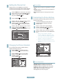
Storing Channels in Memory (Automatic Method)
1. Press the MENU button to display the menu.
Press the or button to select “Channel”, then press the ENTER
button.
2. Press the or button to select "Auto Program", then press the ENTER
TV
Channel
Antenna
: Air
Auto Program
Clear Scrambled Channel
Channel List
Name
Fine Tune
Signal Strength
button.
Move
3. Press the or button to select the antenna connection, then press the
ENTER
button.
Enter
TV
Selects the antenna to execute the Auto
Program function.
Air
Start
Cable
Start
Auto
Start
Move
Move
Enter
Enter
TV
Selects a cable signal type for your location.
Analog
STD
HRC
IRC
Start
Digital
STD
HRC
IRC
Move
Move
Enter
Enter
Return
Return
Auto
PlugProgram
& Play
Auto Program in Progress.
DTV Cable : --
Cable : 11
Cable 24
11 %
5. The TV begins memorizing all available stations.
After all the available channels are stored, it start to remove scrambled
channels(see page 39).
If you want to stop Auto Programming, press the ENTER
button. The “Stop
Auto Program?” message will be displayed. Select “Yes” by pressing the or button, then press the ENTER
button.
Return
Return
Auto Program
Press the or button, then press the or to select the correct analog signal
button.
cable system source among “STD”, “HRC”, and “IRC”. Press the ENTER
If you have Digital cable TV, select the cable system signal source for both Analog
and Digital.
STD, HRC and IRC identify various types of cable TV systems. Contact your
local cable company to identify the type of cable system that exists in your
particular area. At this point the signal source has been selected.
Return
Auto Program
Air: “Air” antenna signal.
Cable: “Cable” antenna signal.
Auto: “Air” and “Cable” antenna signals.
4. When selecting the Cable TV system:
button to start the auto program.
Press the ENTER
Stop
Enter
Return
Auto
PlugProgram
& Play
Removing scrambled channel.
DTV Cable 55
80 %
Press the EXIT button to exit.
Stop
Enter
Return
Auto Program
Stop Auto Program?
DTV Cable : --
Cable : 11
11
Yes
Move
%
No
Enter
Return
Auto Program
Auto Program is completed.
99 Channels are memorized.
DTV Cable : 65, Cable : 34
OK
Enter
English - 25
Return
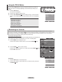
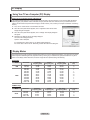
To Select the Source
Use to select TV or other external input sources such as DVD players or Cable Box/
Satellite receivers (Set-Top Box) connected to the TV. Use to select the input source
of your choice.
1. Press the MENU button to display the menu.
Press the or button to select “Input”, then press the ENTER
TV
Input
Source List
: TV
Edit Name
Anynet+ (HDMI-CEC)
button.
button to select "Source List".
2. Press the ENTER
Press the or button to select signal source, then press the ENTER
button.
Move
Available signal sources: TV, AV1, AV2, S-Video, Component1, Component2,
PC, HDMI1, HDMI2, HDMI3.
You can choose only those external devices that are connected to the TV.
TV
Enter
Return
Source List
TV
AV1
AV2
S-Video
Component1
Component2
PC
More
Move
: ---: ---: ---: ---: ---: ---Enter
Return
Press the SOURCE button on the remote control to view an external signal source.
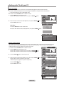
To Edit the Input Source Name
Name the device connected to the input jacks to make your input source selection easier.
1. Press the MENU button to display the menu.
Press the or button to select “Input”, then press the ENTER
button.
button.
Press the or button to select "Edit Name", then press the ENTER
TV
Input
Source List
: TV
Edit Name
Anynet+ (HDMI-CEC)
Move
2. Press the or button to select "AV1", "AV2", "S-Video", "Component1",
"Component2", "PC", "HDMI1", "HDMI2", "HDMI3" input jack, then press the
ENTER
button.
TV
TV
Return
:
:
:
:
:
:
:
----------------------
Enter
Return
Edit Name
AV1
AV2
S-Video
Component1
Component2
PC
HDMI1
More
Move
English - 26
Enter
Edit Name
AV1
AV2
S-Video
Component1
Component2
PC
HDMI1
More
Move
3. Press the or button to select “VCR”, “DVD”, “Cable STB”, “Satellite STB”,
“PVR STB”, “AV Receiver”, “Game”, “Camcorder”, “PC”, “TV”, “IPTV”, “Blu-Ray”,
“HD DVD”, “Digital Media Adapter” input source, then press the ENTER
button.
Press the EXIT button to exit.
: ------: ---VCR
: ---DVD
: ---Cable STB
: ---Satellite STB
: ---PVR STB
AV Receiver
: ---Game
Enter
Return
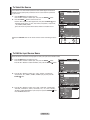
Picture Control
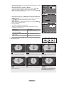
Changing the Picture Standard
You can activate either Dynamic, Standard, Movie by making a selection from the menu.
1. Press the MENU button to display the menu.
button, to select “Picture”.
Press the ENTER
TV
Picture
Mode
Backlight
Contrast
Brightness
Sharpness
Color
Tint
G 50
More
2. Press the ENTER
button to select "Mode".
Press the or button to select the “Dynamic”, “Standard” or “Movie”.
: Standard
Move
Enter
TV
3. Press the EXIT button to exit.
Return
Picture
Mode
Backlight
Contrast
Brightness
Sharpness
Color
Tint
G 50
More
Dynamic: Selects the picture for high-denition in a bright room.
Standard: Selects the picture for the optimum display in a normal environment.
Movie: Selects the picture for viewing movies in a dark room.
7
95
45
50
50
R 50
: Dynamic
Dynamic
Standard
Movie
Move
7
95
45
50
50
R 50
Enter
Return
Tools
Easy Setting
Anynet+(HDMI-CEC)
Picture Mode
Standard Sound Mode
:
Custom
Sleep Timer
:
Off
Add to Favorite
Switch to Air
1. Press the TOOLS button on the remote control.
2. Press the or button to select “Picture Mode”.
3. Press the or button to select the required option.
4. Press the EXIT or TOOLS button to exit.
Move
Adjust
Exit
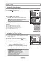
Customizing the Picture Settings
Your television has several setting options that allow you to control the picture quality.
1. To select the desired picture mode, follow the “Changing the Picture Standard”
instructions numbers 1 and 2.
TV
Picture
Mode
Backlight
Contrast
Brightness
Sharpness
Color
Tint
G 50
More
2. Press the or button to select “Backlight”, “Contrast”, “Brightness”,
button.
“Sharpness”, “Color” or “Tint”, then press the ENTER
3. Press the or button to decrease or increase the value of a particular item.
Press the ENTER
button.
Press the EXIT button to exit.
: Standard
Move
7
95
45
50
50
R 50
Enter
Return
Backlight
° When you make changes to “Backlight”, “Contrast”, “Brightness”, “Sharpness”,
“Color” or “Tint”, the OSD will be adjusted accordingly.
° In PC mode, you can only make changes to “Backlight”, “Contrast” and
“Brightness”.
° Settings can be adjusted and stored for each external device you have
connected to an input of the TV.
• Backlight: Adjusts the brightness of LCD back light.
• Contrast: Adjusts the contrast level of the picture.
• Brightness: Adjusts the brightness level of the picture.
• Sharpness: Adjusts the edge definition of the picture.
• Color: Adjusts color saturation of the picture.
• Tint: Adjusts the color tint of the picture.
English - 27
7
Move
Adjust
Return
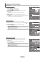
Adjusting the Detailed Settings
Samsung's new TVs allow you to make even more precise picture settings than previous models. See below to adjust detailed
picture settings.
Activating Detailed Settings
TV
Picture
Mode
Backlight
Contrast
Brightness
Sharpness
Color
Tint
G 50
More
1. Press the MENU button to display the menu.
Press the ENTER b utton to select “Picture”.
2. Press the ENTER
button to select “Mode”
Press the or button to select "Standard" or "Movie", then press the
ENTER
button.
"Detailed Settings" is available in "Standard" or "Movie" mode.
: Movie
Move
3. Press the or button to select “Detailed Settings”, then press the
ENTER
button.
In PC mode, you can only make changes to “Dynamic Contrast”, “Gamma” and
“White Balance” from among the “Detailed Settings” items.
TV
5
95
50
20
50
R 50
Enter
Return
Picture
More
Detailed Settings
Picture Options
Reset
: OK
Move
Enter
Return
Setting the Black adjust
You can select the black level on the screen to adjust the screen depth.
4. Press the or button to select “Black adjust”, then press the ENTER
button.
TV
Detailed Settings
Black Adjust
Dynamic Contrast
Gamma
Color Space
White Balance
Flesh Tone
Edge Enhancement
5. Press the or button to select “Off”, “Low”, “Medium” or “High”.
Press the ENTER
button.
Off: Turns off the black adjustment function.
Low: Sets the black color depth to low.
Medium: Sets the black color depth to medium.
High: Sets the black color depth to high.
Move
TV
: Off
: Off
:0
: Off
Enter
0
Return
Detailed Settings
Black Adjust
Dynamic Contrast
Gamma
Color Space
White Balance
Flesh Tone
Edge Enhancement
Move
: Off
Off
: Off
Low
: 0 Medium
High
0
: Off
Enter
Return
Setting the Dynamic Contrast
You can adjust the screen contrast so that the optimal contrast is provided.
6. Press the or button to select “Dynamic Contrast”, then press the
button.
ENTER
TV
7. Press the or button to select “Off”, “Low”, “Medium” or “High”.
button.
Press the ENTER
Off: Turns off the dynamic contrast adjustment function.
Low: Sets the dynamic contrast to low.
Medium: Sets the dynamic contrast to medium.
High: Sets the dynamic contrast to high.
Detailed Settings
Black Adjust
Dynamic Contrast
Gamma
Color Space
White Balance
Flesh Tone
Edge Enhancement
Move
TV
: Off
Enter
0
Return
Detailed Settings
Black Adjust
Dynamic Contrast
Gamma
Color Space
White Balance
Flesh Tone
Edge Enhancement
Move
English - 28
: Off
: Off
:0
: Off
: Off
Off
: 0 Low
Medium
High
0
: Off
Enter
Return
Adjusting the Gamma
TV
You can adjust the Primary Color (Red, Green, Blue) Intensity. (-3 ~ +3)
8. Press the or button to select “Gamma”, then press the ENTER
Detailed Settings
Black Adjust
Dynamic Contrast
Gamma
Color Space
White Balance
Flesh Tone
Edge Enhancement
button.
9. Press the or button to decrease or increase the value.
Press the ENTER
button.
: Off
: Off
:0
0
: Off
Move
Enter
Return
Gamma
0
Adjust
TV
Setting the Color Space
11. Press the ENTER
button.
button again to select “Color Space”.
12. Press the or button to select “Auto”, “Native” or “Custom”.
Press the ENTER
button.
Detailed Settings
Black Adjust
Dynamic Contrast
Gamma
Color Space
White Balance
Flesh Tone
Edge Enhancement
Color space is a color matrix composed of red, green and blue colors.
Select your favorite color space to experience the most natural color.
10. Press the or button to select “Color Space”, then press the ENTER
Return
Move
TV
• Native: Native Color Space offers deep and rich color tone.
• Custom: Adjusts the color range to suit your preference.
(see “Customizing the Color Space”)
TV
13. Press the or button to select “Color”, then press the ENTER
Return
: Auto
Auto
: Red
Native
Custom
50
0
0
Enter
Return
Color Space
Color Space
Color
Red
Green
Blue
Reset
button.
: Off
Enter
Move
Customizing the Color Space
0
Color Space
Color Space
Color
Red
Green
Blue
Reset
• Auto: Auto Color Space automatically adjusts to the most natural color
tone based on program sources.
: Off
: Off
:0
: Custom
: Red
50
0
0
° “Color” is available when “Color Space” is set to “Custom”.
14. Press the or button to select “Red”, “Green”, “Blue”, “Yellow”, “Cyan” or
button.
“Magenta”. Press the ENTER
15. Press the or button to select “Red”, “Green” or “Blue” to change it.
Press the ENTER
button.
Move
TV
Enter
Color Space
Color Space
Color
Red
Green
Blue
Reset
16. Press the or button to decrease or increase the value of a particular item.
button.
Press the ENTER
° In “Color”, you can adjust the RGB values for the selected color.
Return
: Custom
: Red
Red
Green
Blue
Yellow
Cyan
Magenta
50
0
0
° To reset the adjusted RGB value, select “Reset”.
Move
Enter
Return
• Red: Adjusts the red saturation level of the selected color.
• Green: Adjusts the green saturation level of the selected color.
• Blue: Adjusts the blue saturation level of the selected color.
• Reset: Resets the color space to the default values.
° Changing the adjustment value will refresh the adjusted screen.
° Settings can be adjusted and stored for each external device you have
connected to an input of the TV. For example, if you have a DVD player
connected to HDMI 1 and it is currently selected, settings and adjustments will
be saved for the DVD player.
English - 29
Red
50
Move
Adjust
Return
Adjusting the White Balance
TV
Detailed Settings
Black Adjust
Dynamic Contrast
Gamma
Color Space
White Balance
Flesh Tone
Edge Enhancement
You can adjust the color temperature for more natural picture colors.
17. Press the or button to select “White Balance”, then press the ENTER
button.
18. Select the required option by pressing the or button, then press the
ENTER
button.
19. Press the or button to decrease or increase the value of a particular item.
Press the ENTER
button.
Move
TV
R-Offset: Adjusts the red color darkness.
G-Offset: Adjusts the green color darkness.
B-Offset: Adjusts the blue color darkness.
R-Gain: Adjusts the red color brightness.
G-Gain: Adjusts the green color brightness.
B-Gain: Adjusts the blue color brightness.
Reset: The previously adjusted white balance will be reset to the factory defaults.
: Off
: Off
:0
0
: Off
Enter
Return
White Balance
R-Offset
G-Offset
B-Offset
R-Gain
G-Gain
B-Gain
Reset
25
25
25
25
25
25
Move
Enter
Return
Changing the adjustment value will refresh the adjusted screen.
R-Offset
25
Move
Adjusting the Flesh Tone
Adjust
TV
Detailed Settings
Black Adjust
Dynamic Contrast
Gamma
Color Space
White Balance
Flesh Tone
Edge Enhancement
You can emphasize the pink ‘flesh tone’ in the picture.
20. Press the or button to select “Flesh Tone”, then press the ENTER
button.
21. Press the or button to decrease or increase the value.
Press the ENTER
button.
Return
Changing the adjustment value will refresh the adjusted screen.
Move
: Off
: Off
:0
0
: Off
Enter
Return
Flesh Tone
0
Adjust
Setting the Edge Enhancement
TV
Detailed Settings
Black Adjust
Dynamic Contrast
Gamma
Color Space
White Balance
Flesh Tone
Edge Enhancement
You can emphasize object boundaries in the picture.
22. Press the or button to select “Edge Enhancement”, then press the
ENTER
button.
23. Press the or button to select “Off” or “On”.
Press the ENTER
button.
Move
TV
: Off
: Off
:0
: Off
Enter
0
Return
Detailed Settings
Black Adjust
Dynamic Contrast
Gamma
Color Space
White Balance
Flesh Tone
Edge Enhancement
Move
English - 30
Return
: Off
: Off
:0
: Off
Off
On
Enter
0
Return
Conguring Picture Options
Activating Picture Options
1. Press the MENU button to display the menu.
Press the ENTER
button, to select “Picture”.
TV
2. Press the or button to select "Picture Options", then press the
ENTER
button.
Picture
More
Detailed Settings
Picture Options
Reset
: OK
Press the or button to select a particular item. Press the ENTER
button.
When you are satisfied with your setting, press the ENTER
button.
In PC mode, you can only make changes to the “Color Tone” and “Size” from
among the items in “Picture Options”.
Move
Setting the Color Tone
TV
1. Follow the “Activating Picture Options” instructions numbers 1 and 2. (Refer to
page 31)
2. Press the or button to select “Color Tone”, then press the ENTER
3. Press the or button to select “Cool2”, “Cool1”, “Normal”, “Warm1” or “Warm2”.
button.
Press the ENTER
Return
Picture Options
Color Tone
: Normal
Size
: 16:9
Digital NR
: Auto
DNle
: Off
HDMI Black Level : Normal
Film Mode
: Off
Blue Only Mode : Off
button.
“Warm1” or “Warm2” is only activated when the picture mode is “Movie”.
Settings can be adjusted and stored for each external device you have connected
to an input of the TV.
Enter
Move
TV
Enter
Return
Picture Options
Color Tone
: Cool1
Cool2
Cool1
Size
: 16:9
Normal
Digital NR
: Auto
Warm1
DNle
: On
Warm2
HDMI Black Level : Normal
Film Mode
: Off
Blue Only Mode : Off
Move
Enter
Return
Setting the Screen Size
Occasionally, you may want to change the size of the image on your screen. Your TV
comes with six screen size options, each designed to work best with specific types of
video input. Your cable box or satellite receiver may have its own set of screen sizes as
well. In general, though, you should view the TV in 16:9 mode as much as possible.
TV
1. Follow the “Activating Picture Options” instructions numbers 1 and 2.
(Refer to page 31)
2. Press the or button to select “Size”, then press the ENTER
button.
3. Press the or button to select the screen format you want.
Press the ENTER
button.
Press the EXIT button to exit.
• 16:9 : Sets the picture to 16:9 wide mode.
• Zoom1: Magnifies the size of the picture on the screen.
• Zoom2: Magnifies the size of the picture more than “Zoom1”.
• Wide Fit: Enlarges the aspect ratio of the picture to fit the entire screen.
• 4:3 : Sets the picture to 4:3 normal mode.
• Just Scan: Use the function to see the full image without any cutoff when
HDMI (720p/1080i), Component (1080i) or DTV (1080i) signals
are input.
English - 31
Picture Options
Color Tone
: Normal
Size
: 16:9
Digital NR
: Auto
DNle
: Off
HDMI Black Level : Normal
Film Mode
: Off
Blue Only Mode : Off
Move
TV
Enter
Return
Size
16 : 9
Zoom1
Zoom2
Wide Fit
4:3
Just Scan
Move
Enter
Return
° Temporary image retention may occur when viewing a static image on the set
for more than two hours.
TV
Size
16 : 9
Zoom1
Zoom2
Wide Fit
4:3
Just Scan
° After selecting “Zoom1”, “Zoom2” or “Wide Fit”:
Press the or button to select “Position”, then press the ENTER
button. Press the or button to move the picture up and down.
Reset: Press the or button to select “Reset”, then press the ENTER
button. You can initialize the setting.
Position
Adjust
Enter
TV
Size
Picture Size
16:9, Zoom1, Zoom2, 4:3
DTV(1080i), Component (1080i), HDMI
(720p, 1080i)
16:9, 4:3, Wide Fit, Just Scan
PC
16:9, 4:3
Enter
Return
Just Scan
H-Position
V-Position
Reset
° Settings can be adjusted and stored for each external device you have
connected to an input of the TV.
TV, Video, S-Video,
Component (480i, 480p)
Move
TV
Input Source
Return
16 : 9
Zoom1
Zoom2
Wide Fit
4:3
Just Scan
° After selecting “Just Scan” in HDMI (1080i) or Component (1080i) mode:
Press the or button to select “H-Position” or “V-Position”, then press the
ENTER
button.
Press the or button to adjust the screen Position. Press the
ENTER
button.
Reset: Press the or button to select “Reset”, then press the ENTER
button. You can initialize the setting.
° HD (High Definition)
16:9 - 1080i (1920x1080), 720p (1280x720)
Reset
Move
0
0
Enter
Return
O Alternately, you can press the P.SIZE button on the remote control repeatedly to
change the picture size.
Zoom1 U Move
16:9
Zoom2 U Move
16:9
Zoom1
Zoom2
Sets the picture to 16:9 wide mode.
Magnifies the size of the picture on the
screen.
Magnifies the size of the picture more
than “Zoom1”.
4:3
Just Scan
Wide Fit U Move
Wide Fit
4:3
Just Scan
Enlarges the aspect ratio of the picture
to fit the entire screen.
Sets the picture to 4:3 normal mode.
Use the function to see the full
image without any cutoff when HDMI
(720p/1080i), Component (1080i) or
DTV (1080i) signals are input.
English - 32
Setting the Digital Noise Reduction
If the broadcast signal received by your TV is weak, you can activate the Digital Noise
Reduction feature to help reduce any static and ghosting that may appear on the screen.
TV
1. Follow the “Activating Picture Options” instructions numbers 1 and 2.
(Refer to page 31)
2. Press the or button to select "Digital NR", then press the ENTER
button.
3. Press the or button to select "Off", "Low", "Medium", "High" or "Auto".
Press the ENTER
button.
Off: Turns the screen noise reduction function off.
Low: Reduces screen noise at a low level.
Medium: Reduces screen noise at a medium level.
High: Reduces screen noise at a high level.
Auto: Automatically recognizes and reduces screen noise.
Picture Options
Color Tone
: Normal
Size
: 16:9
Digital NR
: Auto
DNle
: Off
HDMI Black Level : Normal
Film Mode
: Off
Blue Only Mode : Off
Move
TV
Enter
Return
Picture Options
Color Tone
: Normal
Size
: 16:9
Digital NR
: Auto
Off
Low
DNle
: On
Medium
HDMI Black Level : Normal
High
Film Mode
: Off
Auto
Blue Only Mode : Off
Press the EXIT button to exit.
Move
Setting the DNIe (Digital Natural Image engine)
TV
This TV includes the DNIe function to provide high visual quality. If you set DNIe to on,
you can view the screen with the DNIe feature activated.
button.
3. Press the or button to select "Off" or "On", then press the ENTER
Return
Picture Options
Move
button.
TV
• Off: Switches off the "DNIe" mode.
• On: Switches on the "DNIe" mode.
Enter
Color Tone
: Cool1
Size
: 16:9
Digital NR
: Auto
DNle
: On
HDMI Black Level : Normal
Film Mode
: Off
Blue Only Mode : Off
1. Follow the “Activating Picture Options” instructions numbers 1 and 2.
(Refer to page 31)
2. Press the or button to select "DNIe", then press the ENTER
Enter
Return
Picture Options
Color Tone
: Cool1
Size
: 16:9
Digital NR
: Auto
DNle
: On
Off
On
HDMI Black Level : Normal
Film Mode
: Off
Blue Only Mode : Off
Press the EXIT button to exit.
° DNIe™ (Digital Natural Image engine)
This feature brings you a more detailed image with 3D noise reduction and
detail, contrast and white enhancement.
° “DNIe” is only available in “Dynamic” mode.
Move
Enter
Return
Setting the HDMI Black Level
You can select the black level on the screen to adjust the screen depth.
TV
1. Follow the “Activating Picture Options” instructions numbers 1 and 2.
(Refer to page 31)
2. Press the or button to select “HDMI Black Level”, then
button.
press the ENTER
3. Press the or button to select “Normal” or “Low”, then press
button.
the ENTER
• Normal: The screen gets brighter.
• Low: The screen gets darker.
° This function is active only when an external device is connected to the TV via
HDMI. “HDMI Black Level” function may not be compatible with all external
devices.
Press the EXIT button to exit.
Picture Options
Color Tone
: Normal
Size
: 16:9
Digital NR
: Auto
DNle
: Off
HDMI Black Level : Low
Film Mode
: Off
Blue Only Mode : Off
Move
TV
Return
Picture Options
Color Tone
: Normal
Size
: 16:9
Digital NR
: Auto
DNle
: Off
HDMI Black Level : Normal
Normal
Low
Film Mode
: Off
Blue Only Mode
Move
English - 33
Enter
: Off
Enter
Return
Setting the Film Mode
The TV can be set to automatically sense and process lm signals from all sources and
adjust the picture for optimum quality.
TV
1. Follow the “Activating Picture Options” instructions numbers 1 and 2.
(Refer to page 29)
2. Press the or button to select "Film Mode", then press the ENTER
Picture Options
Color Tone
: Normal
Size
: 16:9
Digital NR
: Auto
DNle
: Off
HDMI Black Level : Normal
Film Mode
: Off
Blue Only Mode : Off
button.
Move
TV
3. Press the or button to select "Off" or "Auto", then press the ENTER
Enter
Return
Picture Options
Color Tone
: Normal
Size
: 16:9
Digital NR
: Auto
DNle
: Off
HDMI Black Level : Normal
Film Mode
: Off
Off
Blue Only Mode : Off
Auto
button.
Press the EXIT button to exit.
"Film mode" is supported in TV, VIDEO, S-VIDEO, COMPONENT(480i / 1080i)
and HDMI(480i / 1080i).
Move
Enter
Return
Setting the Blue Only Mode
This function is for AV device measurement experts. This function displays the blue
signal only by removing the red and green signals from the video signal so as to provide
a Blue Filter effect that is used to adjust the Color and Tint of video equipment such as
DVD players, Home Theaters, etc.
TV
Using this function, you can adjust the Color and Tint to preferred values appropriate to
the signal level of each video device using the Red/Green/Blue/ Cyan/Magenta/Yellow
Color Bar Patterns, without using an additional Blue Filter.
1. Follow the “Activating Picture Options” instructions numbers 1 and 2.
(Refer to page 29).
Move
2. Press the or button to select "Blue Only Mode", then press the ENTER
button.
3. Press the or button to select "Off" or "On", then press the ENTER
Picture Options
Color Tone
: Normal
Size
: 16:9
Digital NR
: Auto
DNle
: Off
HDMI Black Level : Normal
Film Mode
: Off
Blue Only Mode : Off
TV
Enter
Return
Picture Options
Color Tone
: Normal
Size
: 16:9
Digital NR
: Auto
DNle
: Off
HDMI Black Level : Normal
Film Mode
: Off
Blue Only Mode : Off
Off
On
button.
Press the EXIT button to exit.
Move
Enter
Return
“Blue Only Mode” is available when the picture mode is set to “Movie” or
“Standard”.
Resetting the Picture Settings to the Factory Defaults
1. Press the MENU button to display the menu.
Press the ENTER
button, to select “Picture”.
TV
button.
2. Press the or button to select "Reset", then press the ENTER
Press the or button to select “OK” or “Cancel” then press the ENTER
button.
Picture
More
Detailed Settings
Picture Options
Reset
: OK
OK
Cancel
Press the EXIT button to exit.
Each mode can be reset.
Move
English - 34
Enter
Return
Sound Control
Changing the Sound Standard
You can select the sound mode to best suit the programming you’re watching.
1. Press the MENU button to display the menu.
Press the or button to select "Sound", then press the ENTER
TV
Sound
Mode
: Custom
Equalizer
SRS TruSurround XT : Off
Multi-Track Options
Auto Volume
: Off
TV Speaker
: On
button.
Move
2. Press the ENTER button to select "Mode".
Press the or button to select “Standard”, “Music”, “Movie”, “Speech”, or
button.
“Custom” sound setting, then press the ENTER
TV
Return
Sound
Mode
: Custom
Standard
Equalizer
Music
SRS TruSurround XT : Off
Movie
Multi-Track Options
Speech
Auto Volume
: Off
Custom
TV Speaker
: On
Press the EXIT button to exit.
•
•
•
•
•
Enter
Standard: selects the normal sound mode.
Music: emphasizes music over voices.
Movie: provides the best sound for movies
Speech: emphasizes voice over other sounds.
Custom: recalls your customized sound settings.
(see “Customizing the Sound”)
Move
Enter
Return
Tools
Easy Setting
Anynet+(HDMI-CEC)
Picture Mode
: Standard
Sound Mode
Custom Sleep Timer
:
Off
Add to Favorite
Switch to Air
1. Press the TOOLS button on the remote control.
2. Press the or button to select “Sound Mode”.
3. Press the or button to select the required option.
4. Press the EXIT or TOOLS button to exit.
Move
Adjust
Exit
Customizing the Sound
The sound settings can be adjusted to suit your personal preference.
1. Press the MENU button to display the menu.
Press the or button to select "Sound", then press the ENTER
2. Press the or button to select "Equalizer", then press the ENTER
TV
button.
Sound
Mode
: Custom
Equalizer
SRS TruSurround XT : Off
Multi-Track Options
Auto Volume
: Off
TV Speaker
: On
button.
Move
3. Press the or button to select a particular frequency to adjust.
Press the or button to increase or decrease the level of the particular frequency.
Press the ENTER
TV
Enter
Return
Equalizer
R
button.
+
0
Press the EXIT button to exit.
L
Balance
• L/R SoundBalance Adjustment: To adjust the sound balance of the L/R
speakers.
• Bandwidth Adjustment (100Hz, 300Hz, 1KHz, 3KHz, 10KHz):To adjust the
level of different bandwidth frequencies.
If you make any changes to the "Equalizer" settings, the sound mode is
automatically switched to the "Custom" mode.
English - 35
100Hz 300Hz 1KHz 3KHz 10KHz
Move
Adjust
Return
Setting the TruSurround XT
TruSurround XT is a patented SRS technology that solves the problem of playing 5.1 multichannel content over two speakers.
TruSurround delivers a compelling, virtual surround sound experience through any two-speaker playback system, including internal
television speakers. It is fully compatible with all multichannel formats.
1. Press the MENU button to display the menu.
TV
Sound
Press the or button to select "Sound", then press the ENTER
button.
Mode
: Custom
Equalizer
SRS TruSurround XT : Off
Multi-Track Options
Auto Volume
: Off
TV Speaker
: On
2. Press the or button to select "SRS TruSurround XT", then press the
button.
ENTER
Move
3. Press the or button to select "Off" or "On", then press the ENTER
button.
TV
Enter
Return
Sound
Mode
: Custom
Equalizer
SRS TruSurround XT : Off
Off
Multi-Track Options
On
: Off
Auto Volume
TV Speaker
: On
Press the EXIT button to exit.
TruSurround XT, SRS and
Symbol are trademarks of
SRS Labs, Inc.
TruSurround XT technology is incorporated under license
from SRS Labs, Inc.
Move
Enter
Return
Press the SRS button on the remote control to select "Off" or "On".
Choosing a Multi-Channel Sound (MTS) track - Digital
The digital-TV transmission system is capable of simultaneous transmission of many audio tracks (for example, simultaneous
translations of the program into foreign languages). The availability of these additional “multitracks” depends upon the program.
"Multi-Track Options" is available only in TV mode.
Preferred Language
TV
1. Press the MENU button to display the menu.
Press the or button to select "Sound", then press the ENTER
button.
Quick way to access the MTS menu: Just press the “MTS” button on the remote
control. You can listen in a language other than your chosen language by
pressing the MTS button.
2. Press the or button to select “Multi-Track Options", then press the ENTER
button.
Sound
Mode
: Custom
Equalizer
SRS TruSurround XT : Off
Multi-Track Options
Auto Volume
: Off
TV Speaker
: On
Move
TV
Return
Multi-Track Options
Preferred Language
Multi-Track Sound
button to select “Preferred Language”.
3. Press the ENTER
Press the or button to choose the language (English, Spanish or French) you
want, then press the ENTER
button.
Enter
: English
: Stereo
Press the EXIT button to exit.
“Preferred Language” is available only in Digital TV mode.
Enter
You can only select the language from among the actual languages being broadcast.
TV
Return
Multi-Track Options
Preferred Language
Multi-Track Sound
: English
English
: Stereo
Spanish
French
Move
You can listen in a language other than the Preferred language by pressing
the MTS button on the remote control.
English - 36
Enter
Return
Choosing a Multi-Channel Sound (MTS) track - Analog
Multi-Track Sound
TV
1. Press the MENU button to display the menu.
Press the or button to select "Sound", then press the ENTER
Multi-Track Options
Preferred Language
Multi-Track Sound
button.
: English
: Stereo
2. Press the or button to select "Multi-Track Options", then press the
button.
ENTER
Enter
3. Press the or button to select “Multi-Track Sound”, then press the ENTER
button.
Press the or button to select a setting you want, then press the ENTER
button.
Press the EXIT button to exit.
TV
Return
Multi-Track Options
Preferred Language
Multi-Track Sound
: English
: Stereo
Mono
Stereo
SAP
• Mono: Choose for channels that are broadcasting in mono or if you are having
difficulty receiving a stereo signal.
• Stereo: Choose for channels that are broadcasting in stereo.
• SAP: Choose to listen to the Separate Audio Program, which is usually a
foreign-language translation.
Move
Enter
Return
“Multi-Track Sound” is available only in Analog TV mode.
Depending on the particular program being broadcast, you can listen to “Mono”,
“Stereo” or “SAP”.
Press the MTS buttons on the remote control repeatedly to select “Mono”,
“Stereo” or “SAP”.
Automatic Volume Control
Reduces the differences in volume level among broadcasters.
1. Press the MENU button to display the menu.
Press the or button to select "Sound", then press the ENTER
button.
2. Press the or button to select "Auto Volume", then press the ENTER
3. Press the or button to set Auto Volume "Off" or "On" then press the
ENTER
button.
TV
Sound
Mode
: Custom
Equalizer
SRS TruSurround XT : Off
Multi-Track Options
Auto Volume
: Off
TV Speaker
: On
button.
Move
TV
Enter
Return
Sound
Mode
: Custom
Equalizer
SRS TruSurround XT : Off
Multi-Track Options
Auto Volume
: Off
Off
TV Speaker
: On
On
Press the EXIT button to exit.
Move
English - 37
Enter
Return
Setting the TV Speakers On/Off
Sound output from the TV speakers is muted.
1. Press the MENU button to display the menu.
Press the or button to select "Sound", then press the ENTER
TV
2. Press the or button to select "TV Speaker", then press the ENTER
Sound
Mode
: Custom
Equalizer
SRS TruSurround XT : Off
Multi-Track Options
Auto Volume
: Off
TV Speaker
: On
button.
button.
Move
TV
3. Press the or button to select “Off”, then press the ENTER
button.
Press the EXIT button to exit.
When “TV Speaker” is set to “Off”, Sound menus except “Multi-Track Options”
cannot be adjusted.
The VOL , VOL
is set to “Off”.
Return
Sound
Mode
: Custom
Equalizer
SRS TruSurround XT : Off
Multi-Track Options
Auto Volume
: Off
TV Speaker
: On
Off
On
and MUTE buttons do not operate when the "TV Speaker"
TV’s Internal Speakers
Enter
Move
Enter
Return
Audio Out (Optical, L/R Out) to Sound System
RF
AV, S-Video
Component, PC, HDMI
RF
AV, S-Video
Component, PC, HDMI
TV Speaker On
Speaker Output
Speaker Output
Speaker Output
Sound Output
Sound Output
Sound Output
TV Speaker Off
Mute
Mute
Mute
Sound Output
Sound Output
Sound Output
Video No Signal
Mute
Mute
Mute
Mute
Mute
Mute
Manufactured under license from Dolby Laboratories. Dolby and the double-D symbol are trademarks
of Dolby Laboratories.
Connecting Headphones (Sold separately)
You can connect a set of headphones to your set if you wish to watch a TV program without disturbing other people in the room.
When you insert the headphone’s plug into the headphone jack, you cannot operate
“TV Speaker” in Sound menu.
Prolonged use of headphones at a high volume may damage your hearing.
You will not hear sound from the speakers when you connect headphones to the TV.
English - 38
TV Side Panel
Channel Control
Clearing Scrambled Channels - Digital
The Clear Scrambled Channel function is used to lter out scrambled channels after Auto Program is completed.
This process may take up to 20~30 minutes.
1. Press the MENU button to display the menu.
Press the or button to select "Channel", then press the ENTER
button.
2. Press the or button to select "Clear Scrambled Channel", then press the
button.
ENTER
It searches scrambled channels, which are to be removed from the list.
To stop searching scrambled channels:
Press the ENTER
button to select Stop.
Press the button to select "Yes", then press the ENTER
TV
Channel
Antenna
: Cable
Auto Program
Clear Scrambled Channel
Channel List
Name
Fine Tune
Signal Strength
Move
Enter
Return
PlugProgram
& Play
Clear Auto
Scrambled
Channel
button.
Removing scrambled channel.
DTV Cable 40
30 %
3. When the scrambled channel searching is completed, press the ENTER
button.
Press the EXIT button to exit.
This function is only available in “Cable” mode.
English - 39
Stop
Enter
Return
Adding and Erasing Channels
Using this menu, you can Add/Delete or set Favorite channels and use the program guide for digital broadcasts.
To use the Channel List function, rst run “Auto Program” (see page 25).
1. Press the MENU button to display the menu.
Press the or button to select "Channel", then press the ENTER
TV
Channel
Antenna
: Cable
Auto Program
Clear Scrambled Channel
Channel List
Name
Fine Tune
Signal Strength
button.
2. Press the or button to select "Channel List", then press the ENTER
button.
Move
3. Press the ENTER
TV
button to select “All”.
Enter
Move
Press the or button to select “Delete”, then press the ENTER
delete the channel.
The
button to
mark will disappear.
Return
Channel List
All
Added
Favorite
Default List Mode
4. Press the , , or button to select a channel to delete, then press the
ENTER
button.
: All
Enter
Return
Channel List / All
Air 5
1/2
Air 9
Air 10
DTV Air 10-1
DTV Air 10-2
Watch
Add
DTV Air 10-3
Delete
DTV Air 10-1
Favorite
DTV Air 10-2
DTV Air 10-3
Add All
DTV Air 2-1
Air3
Air4
Air 5
Air 6
Air 7
DTV Air 7-1
Air 8
List Mode
Move
Enter
DTV Air 10-1
DTV Air 10-2
DTV Air 10-3
Air 12
DTV Air 13-1
DTV Air 13-2
DTV Air 13-3
DTV Air 13-4
Delete All
Return
Channel List / All
Air 5
1/2
DTV Air 2-1
Air3
Air4
Air 5
Air 6
Air 7
DTV Air 7-1
Air 8
List Mode
Move
5. Press the , , or button to select a channel to add, then press the
ENTER
button.
Press the or button to select “Add”, then press the ENTER
add the channel.
The
button to
mark will appear and the channel will be added.
Press the EXIT button to exit.
All selected channels will be shown on “Added" menu.
• Red button: Press repeatedly to select “All”, “Added” or “Favorite”.
• Green button: Press to add all deleted channels.
• Yellow button: Press to delete all memorized channels.
Enter
Page
DTV Air 10-1
DTV Air 10-2
DTV Air 10-3
Air 12
DTV Air 13-1
DTV Air 13-2
DTV Air 13-3
DTV Air 13-4
Delete All
Return
Channel List / All
Air 5
1/2
DTV Air 2-1
Air3
Air4
Air 5
Air 6
Air 7
DTV Air 7-1
Air 8
List Mode
Move
Air 9
Air 10
DTV Air 10-1
Watch
DTV Air 10-2
Add
DTV Air 10-3
Delete
DTV Air 10-1
Favorite
DTV Air 10-2
DTV Air 10-3
Add All
Enter
DTV Air 10-1
DTV Air 10-2
DTV Air 10-3
Air 12
DTV Air 13-1
DTV Air 13-2
DTV Air 13-3
DTV Air 13-4
Delete All
Return
Channel List / All
Air 5
1/2
DTV Air 2-1
Air3
Air4
Air 5
Air 6
Air 7
DTV Air 7-1
Air 8
List Mode
Move
English - 40
Air 9
Air 10
DTV Air 10-1
DTV Air 10-2
DTV Air 10-3
DTV Air 10-1
DTV Air 10-2
DTV Air 10-3
Add All
Air 9
Air 10
DTV Air 10-1
DTV Air 10-2
DTV Air 10-3
DTV Air 10-1
DTV Air 10-2
DTV Air 10-3
Add All
Enter
Page
DTV Air 10-1
DTV Air 10-2
DTV Air 10-3
Air 12
DTV Air 13-1
DTV Air 13-2
DTV Air 13-3
DTV Air 13-4
Delete All
Return
To Set-Up Your Favorite Channels
You can set channels you watch frequently as favorites.
1. Press the MENU button to display the menu.
Press the or button to select "Channel", then press the ENTER
button.
2. Press the or button to select "Channel List", then press the ENTER
TV
Channel
Antenna
: Cable
Auto Program
Clear Scrambled Channel
Channel List
Name
Fine Tune
Signal Strength
button.
Move
3. Press the or button to select "All" or "Added", then press the ENTER
button.
TV
Enter
Return
Channel List
All
Added
Favorite
Default List Mode
: All
Move
Enter
Return
Channel List / Added
4. Press the , , or button to select your favorite channels to watch
among the labeled channels. Then press the ENTER
button.
Press the or button to select “Favorite”, then press the ENTER
button.
The " " symbol will be highlighted and the channel will be set as a Favorite.
To cancel your Favorite channel selection, press the ENTER
button until the
" " symbol is no longer highlighted.
Air 5
Move
Press the EXIT button to exit.
1/2
DTV Air 2-1
Air3
Air4
Air 5
Air 6
Air 7
DTV Air 7-1
Air 8
List Mode
Air 9
Air 10
DTV Air 10-1
DTV Air 10-2
Watch
Add
DTV Air 10-3
Delete
DTV Air 10-1
Favorite
DTV Air 10-2
DTV Air 10-3
Enter
DTV Air 10-1
DTV Air 10-2
DTV Air 10-3
Air 12
DTV Air 13-1
DTV Air 13-2
DTV Air 13-3
DTV Air 13-4
Delete All
Return
Channel List / Added
Only memorized channels can be set as favorite channels.
All favorite channels will be shown in the “Favorite” menu.
Air 5
DTV Air 2-1
Air3
Air4
Air 5
Air 6
Air 7
DTV Air 7-1
Air 8
List Mode
Move
1/2
Air 9
Air 10
DTV Air 10-1
DTV Air 10-2
DTV Air 10-3
DTV Air 10-1
DTV Air 10-2
DTV Air 10-3
Enter
Page
DTV Air 10-1
DTV Air 10-2
DTV Air 10-3
Air 12
DTV Air 13-1
DTV Air 13-2
DTV Air 13-3
DTV Air 13-4
Delete All
Return
To select the favorite channels you have set up, press the FAV.CH button
on the remote control.
Easy Setting
Tools
1. Press the TOOLS button on the remote control.
2. Press the or button to select “Add to Favorite” (or “Delete from Favorite”), then press the
ENTER
button.
The current channel is added to (or deleted from) Favorites.
Anynet+(HDMI-CEC)
Picture Mode
:
Sound Mode
:
Sleep Timer
:
Add to Favorite
Switch to Air
Move
English - 41
Enter
Standard
Custom
Off
Exit
Using the Channel Lists - Analog
Displays the channel list automatically when you press CH LIST button on the remote. (Choose “All”, “Added” or “Favorite”)
1. Press the MENU button to display the menu.
Press the or button to select "Channel", then press the ENTER
TV
button.
Channel
Antenna
: Air
Auto Program
Clear Scrambled Channel
Channel List
Name
Fine Tune
Signal Strength
2. Press the or button to select "Channel List", then press the
button.
ENTER
Move
3. Press the or button to select “Default List Mode” (the channel list you want to
appear when you press CH LIST), then press the ENTER
button.
Press the or button to select “All”, “Added” or “Favorite” then press the
ENTER
button.
TV
Enter
Return
Channel List
All
Added
Favorite
Default List Mode
The Channel list you have chosen will now be set.
: All
All
Added
Favorite
Press the EXIT button to exit.
Move
Enter
Return
Alternately, press the CH LIST button on the remote control to bring up the
Channel Lists.
Viewing the Channel Lists
You can display a list of all channels, added channels or your favorite channels.
1. Press the MENU button to display the menu.
Press the or button to select "Channel", then press the ENTER
TV
Channel
Antenna
: Cable
Auto Program
Clear Scrambled Channel
Channel List
Name
Fine Tune
Signal Strength
button.
2. Press the or button to select "Channel List", then press the
button.
ENTER
Move
TV
3. Press the or button to select “All”, “Added” or “Favorite”, then press the
ENTER
button.
Enter
• Red button: Press repeatedly to select “All”, “Added” or “Favorite”
All
Added
Favorite
Default List Mode
: All
Enter
Return
Channel List / All
Air 5
1/2
DTV Air 2-1
Air3
Air4
Air 5
Air 6
Air 7
DTV Air 7-1
Air 8
List Mode
Move
English - 42
Return
Channel List
Move
4. Press the or button to select “Channel”, then press the ENTER
button.
To toggle between your all channels, add channels or favorite channels,
use the Red button on the remote control.
Air 9
Air 10
DTV Air 10-1
DTV Air 10-2
DTV Air 10-3
DTV Air 10-1
DTV Air 10-2
DTV Air 10-3
Add All
Enter
Page
DTV Air 10-1
DTV Air 10-2
DTV Air 10-3
Air 12
DTV Air 13-1
DTV Air 13-2
DTV Air 13-3
DTV Air 13-4
Delete All
Return
Labeling Channels
Channels can be labeled so that their call letters appear whenever the channel is selected.
1. Press the MENU button to display the menu.
Press the or button to select “Channel”, then press the ENTER
button.
Press the or button to select “Name”, then press the ENTER
button.
TV
Channel
Antenna
: Air
Auto Program
Clear Scrambled Channel
Channel List
Name
Fine Tune
Signal Strength
Move
2. Press the or button to select the channel to be assigned a new name,
button.
then press the ENTER
Press the or button to select a letter, a number or a blank (Results in this
sequence: A...Z, 0...9, +, -, *, /, blank).
Press the button to switch to the next field, which will be selected.
Select a second letter or digit by pressing the or button, as above.
Repeat the process to select the last three digits. When you have finished,
press the ENTER
button to assign the new name.
To erase the assigned new name, select "Clear" by pressing the or button,
button.
then press the ENTER
Press the EXIT button to exit.
° The names of digital broadcasting channels are automatically assigned and
cannot be labelled.
Enter
TV
Return
Name
Air
2
Clear
Air
3
Clear
Air
4
Clear
Air
5
Clear
Air
6
Clear
Move
Enter
TV
Return
Name
Air
2
Air
3
Clear
Air
4
Clear
Air
5
Clear
Air
6
Clear
Move
English - 43
A
Clear
Adjust
Return
Fine Tuning Analog Channels
Use ne tuning to manually adjust a particular channel for optimal reception.
1. Press the MENU button to display the menu.
Press the or button to select "Channel", then press the ENTER
2. Press the or button to select "Fine Tune", then press the ENTER
TV
button.
Channel
Antenna
: Air
Auto Program
Clear Scrambled Channel
Channel List
Name
Fine Tune
Signal Strength
button.
Move
3. Press the or button to adjust the fine tuning.
To store the fine tuning setting in the TV’s memory, press the ENTER
Enter
Return
Fine Tune
button.
Air 24
0
If you do not store the fine-tuned channel in memory, adjustments are not saved.
4. To reset the fine tuning setting, press the button to select "Reset",
then press the ENTER
button.
Reset
Adjust
Press the EXIT button to exit.
"*" will appear next to the name of fine-tuned channels.
Save
Return
Fine Tune
Air 24 *
Only analog TV channels can be fine tuned.
Fine Tuned
+3
Reset
Adjust
Save
Return
Fine Tune
Air 24
0
Reset
Move
Enter
Return
Checking the Digital-Signal Strength
Unlike analog channels, which can vary in reception quality from “snowy” to clear, digital (HDTV) channels have either perfect
reception quality or you will not receive them at all. So, unlike analog channels, you cannot ne tune a digital channel. You can,
however, adjust your antenna to improve the reception of available digital channels.
1. Press the MENU button to display the menu.
Press the or button to select “Channel”, then press the ENTER
TV
2. Press the or button to select “Signal Strength”, then press the ENTER
button.
If the signal strength meter indicates that the signal is weak, physically adjust your
antenna to increase the signal strength.
Continue to adjust the antenna until you find the best position with the strongest
signal.
Move
TV
Press the EXIT button to exit.
Channel
Antenna
: Cable
Auto Program
Clear Scrambled Channel
Channel List
Name
Fine Tune
Signal Strength
button.
Enter
Return
Signal Strength
OK
Enter
English - 44
Return
PC Display
Using Your TV as a Computer (PC) Display
Setting Up Your PC Software (Based on Windows XP)
The Windows display-settings for a typical computer are shown below. The actual screens on your PC will probably be different,
depending upon your particular version of Windows and your particular video card. However, even if your actual screens look
different, the same basic set-up information will apply in almost all cases. (If not, contact your computer manufacturer or Samsung
Dealer.)
1. First, click on "Control Panel" on the Windows start menu.
2. When the control panel window appears, click on "Appearance and Themes" and a
display dialog-box will appear.
3. When the control panel window appears, click on "Display" and a display dialog-box
will appear.
4. Navigate to the "Settings" tab on the display dialog-box.
The correct size setting (resolution)
Optimum: 1360 X 768 pixels
If a vertical-frequency option exists on your display settings dialog box,
the correct value is "60" or "60 Hz". Otherwise, just click "OK" and exit the dialog box.
Display Modes
If the signal from the system equals the standard signal mode, the screen is adjusted automatically. If the signal from the system
doesn’t equal the standard signal mode, adjust the mode by referring to your videocard user guide; otherwise there may be no
video. For the display modes listed below, the screen image has been optimized during manufacturing.
D-Sub Input
Mode
IBM
VESA
Resolution
640x350
720×400
640×480
640×480
640×480
800×600
800×600
800×600
1024×768
1024×768
1024×768
1360 x 768
Horizontal
Frequency (kHz)
31.469
31.469
31.469
37.861
37.500
37.879
48.077
46.875
48.363
56.476
60.023
47.712
Vertical
Frequency (Hz)
70.086
70.087
59.940
72.809
75.000
60.317
72.188
75.000
60.004
70.069
75.029
60.015
Pixel Clock
Frequency (MHz)
25.175
28.322
25.175
31.500
31.500
40.000
50.000
49.500
65.000
75.000
78.750
85.500
Sync Polarity
(H/V)
+/-/+
-/-/-/+/+
+/+
+/+
-/-/+/+
+/+
HDMI/DVI Input
Mode
Resolution
VESA
640×480
800×600
1024×768
1360 x 768
Horizontal
Frequency (kHz)
31.469
37.879
48.363
47.712
Vertical
Frequency (Hz)
59.940
60.317
60.004
60.015
English - 45
Pixel Clock
Frequency (MHz)
25.175
40.000
65.000
85.500
Sync Polarity
(H/V)
-/+/+
-/+/+
Setting up the TV with your PC
How to Auto Adjust
Use the Auto Adjust function to have the TV set automatically adjust the video signals it receives.
The function also automatically ne-tunes the settings and adjusts the frequency values and positions.
This function does not work in DVI-Digital mode.
Preset: Press the SOURCE button to select PC mode.
1. Press the MENU button to display the menu.
Press the or button to select “Picture”, then press the ENTER
TV
Picture
button.
2. Press the or button to select "Auto Adjustment", then press the ENTER
Mode
Backlight
Contrast
Brightness
Sharpness
Auto Adjustment
Screen
More
button.
Press the EXIT button to exit.
: Standard
7
95
45
50
Move
Enter
Return
Tools
Easy Setting
1. Press the TOOLS button on the remote control.
button.
2. Press the or button to select “Auto Adjustment”, then press the ENTER
Anynet+(HDMI-CEC)
Picture Mode
:
Sound Mode
:
Sleep Timer
Auto Adjustment
Move
Standard
Custom
Off
Enter
Exit
Auto Adjustment in progress.
Please wait.
Adjusting the Screen Quality
The purpose of the picture quality adjustment is to remove or reduce picture noise. If the noise is not removed by fine tuning
alone, then make the vertical frequency adjustments on your PC and fine tune again. After the noise has been reduced,
re-adjust the picture so that it is aligned on the center of the screen.
TV
Preset: Press the SOURCE button to select PC mode.
1. Press the MENU button to display the menu.
Press the or button to select "Picture", then press the ENTER
Press the or button to select "Screen", then press the ENTER
2. Press the ENTER
button.
button.
button to select "Image Lock".
: Standard
button.
PC
7
95
45
50
Move
3. Press the or button to select "Coarse" or "Fine", then press the ENTER
Press the or button to adjust the screen quality.
Vertical stripes may appear or the picture may be blurry.
Press the ENTER
Picture
Mode
Backlight
Contrast
Brightness
Sharpness
Auto Adjustment
Screen
More
Enter
Return
Screen
Image Lock
Position
Image Reset
Resolution
: 1360x768 @60Hz
button.
Press the EXIT button to exit.
Move
PC
Enter
Return
Image Lock
Coarse
Fine
50
34
Move
Enter
Return
Coarse
50
Move
English - 46
Adjust
Return
Changing the Screen Position
Adjust the PC’s screen positioning if it does not fit the TV screen.
Preset: Press the SOURCE button to select PC mode.
1. Press the MENU button to display the menu.
Press the or button to select "Picture", then press the ENTER
Press the or button to select "Screen", then press the ENTER
2. Press the or button to select "Position", then press the ENTER
PC
Screen
Image Lock
Position
Image Reset
Resolution
button.
button.
: 1360x768 @60Hz
button.
Move
3. Press the or button to adjust the V-Position.
Press the or button to adjust the H-Position.
Press the ENTER
button.
Enter
Return
Position
TV
Press the EXIT button to exit.
Move
Initializing the Screen Position, Coarse and Fine
PC
Preset: Press the SOURCE button to select PC mode.
1. Press the MENU button to display the menu.
Press the or button to select "Picture", then press the ENTER
Press the or button to select "Screen", then press the ENTER
Return
Screen
Image Lock
Position
Image Reset
Resolution
You can replace all image settings with the factory default values.
Enter
: 1360x768 @60Hz
button.
button.
Move
2. Press the or button to select "Image Reset", then press the ENTER
button.
Enter
Return
Image Reset is completed.
Press the EXIT button to exit.
Viewing the Resolution
PC
Screen
Image Lock
Position
Image Reset
Resolution
You can confirm the resolution configured for the PC.
Move
English - 47
: 1360x768 @60Hz
Enter
Return
Time Setting
Setting the Clock
Setting the clock is necessary in order to use the various timer features of the TV.
Also, you can check the time while watching the TV. (Just press the INFO button.)
Option 1: Setting the Clock Manually
1. Press the MENU button to display the menu.
Press the or button to select "Setup", then press the ENTER
Press the or button to select "Time", then press the ENTER
2. Press the ENTER
button.
button.
button to select "Clock".
TV
Setup
Plug & Play
Language
Time
V-Chip
Caption
External Settings
Entertainment
More
Move
TV
: English
: Off
Enter
Return
Time
--/--/----/--:-- -Clock
Sleep Timer
Timer 1
Timer 2
Timer 3
Move
3. Press the ENTER
button to select “Clock Mode”.
Press the or button to select “Manual”, then press the ENTER
button.
TV
Enter
: Manual
Auto
Manual
TV
: Off
Move
Enter
Return
Clock
Clock Mode
Clock Set
Time Zone
DST
: Manual
TV
: Off
Move
5. Press the or button to move to “Month”, “Day”, “Year”, “Hour”, “Minute”,
or “am/pm”. Set the date and time you want by pressing the or button,
button.
then press the ENTER
Return
Clock
Clock Mode
Clock Set
Time Zone
DST
4. Press the or button to select “Clock Set”, then press the ENTER
button.
: Off
: Inactivated
: Inactivated
: Inactivated
Enter
Return
Clock Set
Enter the current date and time.
Month
Day
Year
Minute
am/pm
Press the EXIT button to exit.
Hour
The current time will appear every time you press the INFO button.
You can set the month, day, year, hour and minute directly by pressing the
number buttons on the remote control.
Move
TV
Adjust
Return
Clock Set
Enter the current date and time.
Month
Day
Year
01
01
2008
Hour
Minute
am/pm
12
00
am
Move
English - 48
Adjust
Return
Option 2: Setting the Clock Automatically
The Clock can be set automatically if you are receiving a digital signal.
1. Press the MENU button to display the menu.
Press the or button to select "Setup", then press the ENTER
Press the or button to select "Time", then press the ENTER
TV
Setup
Plug & Play
Language
Time
V-Chip
Caption
External Settings
Entertainment
more
button.
button.
Move
2. Press the ENTER
button to select "Clock".
TV
: English
: Off
Enter
Return
Time
--/--/----/--:-- -Clock
Sleep Timer
Timer 1
Timer 2
Timer 3
Move
3. Press the ENTER
button to select “Clock Mode”.
Press the or button to select “Auto”, then press the ENTER
TV
button.
Enter
Return
Clock
Clock Mode
Clock Set
Time Zone
: Manual
Auto
Manual
DST
: Off
Move
4. Press the or button to select “Time Zone”, then press the ENTER
button.
: Off
: Inactivated
: Inactivated
: Inactivated
TV
Enter
Return
Clock
Clock Mode
Clock Set
Time Zone
DST
Move
: Auto
: Off
Enter
Return
Time Zone
Select the time zone in which you live.
5. Press the or button to highlight the time zone for your local area,
then press the ENTER
button.
Newfoundland
Atlantic
Eastern
Central
Mountain
Pacific
Alaska
Hawaii
Move
6. Press the or button to select “DST”, then press the ENTER
Enter
Return
button.
Press the or button to select “Off” or “On”, then press the ENTER
button.
TV
Clock
Clock Mode
Clock Set
Time Zone
DST
Press the EXIT button to exit.
: Auto
: Off
Depending on the broadcast station and signal, the auto time may not be
set correctly. If this occurs, set the time manually.
The Antenna or cable must be connected in order to set the time automatically.
Move
TV
Clock Mode
Clock Set
Time Zone
DST
Move
English - 49
Enter
Return
Clock
: Auto
: Off
Off
On
Enter
Return
Setting the Sleep Timer
The sleep timer automatically shuts off the TV after a preset time (30, 60, 90, 120, 150 and 180 minutes).
1. Press the MENU button to display the menu.
Press the or button to select "Setup", then press the ENTER
Press the or button to select "Time", then press the ENTER
button.
button.
2. Press the or button to select "Sleep Timer", then press the ENTER
3. Press the or button to adjust “Minute”, then press the ENTER
Setting the Timer sets the “Activation” to “On” automatically.
To cancel the set sleep timer :
Press the or button to select “Activation”.
Press the or button to select “Off”, then press the ENTER
TV
Time
1/ 1/2008 12 : 00 am
Clock
Sleep Timer
Timer 1
Timer 2
Timer 3
button.
button.
: Off
: Inactivated
: Inactivated
: Inactivated
Move
TV
Enter
Return
Sleep Timer
Sets the Seelp Timer options.
Minute
button.
Activation
Off
Press the EXIT button to exit.
Move
TV
Adjust
Return
Sleep Timer
Sets the Seelp Timer options.
Minute
Activation
30
On
Move
Easy Setting
1.
2.
Press the or button to select “Sleep Timer”.
Press the or button to select the minute.
4.
Press the EXIT or TOOLS button to exit.
Return
Tools
Press the TOOLS button on the remote control.
3.
Adjust
Anynet+(HDMI-CEC)
Picture Mode
: Standard
Sound Mode
:
Custom
Sleep Timer
Off
Add to Favorite
Switch to Air
Move
English - 50
Adjust
Exit
Setting the On/Off Timer
1. Press the MENU button to display the menu.
Press the or button to select "Setup", then press the ENTER
Press the or button to select "Time", then press the ENTER
button.
button.
TV
Time
1/ 1/2008 12 : 00 am
2. Three different On/Off Timer Settings can be made. Press the or button to
button.
select “Timer 1”, “Timer 2” or “Timer 3”, then press the ENTER
Clock
Sleep Timer
Timer 1
Timer 2
Timer 3
3. Press the or button to select the desired item below.
: Off
: Inactivated
: Inactivated
: Inactivated
Move
Enter
Return
Press the or button to adjust the setting.
Timer 1
• On Time: Set the Hour, Minute, am/pm, and Activation/Inactivation.
(To activate timer with the setting you’ve chosen, set to
“Activate”.)
• Off Time: Set the Hour, Minute, am/pm, and Activation/Inactivation.
(To activate timer with the setting you’ve chosen, set to
“Activate”.)
On Time
12
:
00
am
:
00
am
Inactivate
Off Time
Volume
Repeat
12
Inactivate
Channel
10
Air 3
Sun Mon Tue Wed Thu
Fri
Sat
Once
• Volume: Set the required volume level.
Move
Adjust
Return
• Channel: Select the desired channel.
• Repeat: Select “Once”, “Everyday”, “Mon~Fri”, “Mon~Sat”, “Sat~Sun”, or
“Manual”.
° When “Manual” is selected, press the button to select the desired
day of the week. Press the ENTER
button over the desired day
and the mark will appear.
Press the EXIT button to exit.
° You can set the hour, minute and channel by pressing the number buttons on
the remote control.
° Auto Power Off
When you set the timer On, the television will eventually turn off, if no controls
are operated for 3 hours after the TV was turned on by the timer. This function
is only available in timer On mode and prevents overheating, which may occur
if a TV is on for too long time.
Function Description
Selecting a Menu Language
1. Press the MENU button to display the menu.
button.
Press the or button to select "Setup", then press the ENTER
Press the or button to select "Language", then press the ENTER
button.
TV
Setup
Plug & Play
Language
Time
V-Chip
Caption
External Settings
Entertainment
More
Move
2. Press the or button to select “English”, “Español” or “Français”.
button.
Press the ENTER
Press the EXIT button to exit.
TV
: Off
Enter
Return
Setup
Plug & Play
Language
Time
V-Chip
Caption
External Settings
Entertainment
More
Move
English - 51
: English
: English
English
Español
Français
: Off
Enter
Return
Using the V-Chip
The V-Chip feature automatically locks out programs that are deemed inappropriate for children. The user must enter a PIN
(personal ID number) before any of the V-Chip restrictions are set up or changed.
“V-Chip” function is not available in HDMI, component or PC mode.
The Screen Saver is activated if there is no remote control key input for longer than 1 minute while setting up the “V-Chip”.
U.S.A Only
This product is covered by the following U.S.patents :US4,930,158,US4,930,160
Setting Up Your Personal ID Number (PIN)
1. Press the MENU button to display the menu.
Press the or button to select "Setup", then press the ENTER
2. Press the or button to select “V-Chip”, then press the ENTER
The message “Enter PIN” will appear. Enter your 4 digit PIN number.
TV
button.
Setup
Plug & Play
Language
Time
V-Chip
Caption
External Settings
Entertainment
More
button.
The default PIN number of a new TV set is “0-0-0-0”.
: English
: Off
Move
Enter
TV
Return
V-Chip
Enter PIN
*
*
*
m..v Enter PIN
3. The “V-Chip” screen will appear.
Press the or button to select “Change PIN”, then press the ENTER
button.
The Change PIN screen will appear. Choose any 4 digits for your PIN and enter
them. As soon as the 4 digits are entered, the “Confirm Password” screen appears.
Re-enter the same 4 digits. When the Confirm screen disappears, your PIN has
been memorized.
TV
V-Chip
V-Chip Lock
: Off
TV Parental Guidelines
MPAA Rating
Canadian English
Canadian French
Downloadable U.S. Rating
Change PIN
Press the EXIT button to exit.
If you forget the PIN, press the remote-control buttons in the following
sequence, which resets the pin to 0-0-0-0 : Power Off. Mute 8 2 4 Power On.
Return
Move
TV
Enter
Return
Change PIN
Enter new PIN.
Confirm Password
m..v Enter PIN
English - 52
Return
How to Enable/Disable the V-Chip
1. Press the MENU button to display the menu.
Press the or button to select "Setup", then press the ENTER
2. Press the or button to select “V-Chip”, then press the ENTER
The message “Enter PIN” will appear. Enter your 4 digit PIN number.
TV
button.
Setup
Plug & Play
Language
Time
V-Chip
Caption
External Settings
Entertainment
More
button.
: Off
Move
TV
: English
Enter
Return
V-Chip
Enter PIN
*
*
*
m..v Enter PIN
3. The “V-Chip” screen will appear.
To enable the V-Chip feature, press the ENTER
button so that the “V-Chip Lock”
field is “On”. (Pressing the or button will alternate between “On” and “Off”.)
Press the ENTER
TV
Return
V-Chip
V-Chip Lock
: Off
TV Parental Guidelines
MPAA Rating
button.
Canadian English
Canadian French
Downloadable U.S. Rating
Change PIN
Press the EXIT button to exit.
Move
Enter
TV
Return
V-Chip
V-Chip Lock
: off
TV Parental Guidelines
MPAA Rating
Canadian English
Canadian French
Downloadable U.S. Rating
Change PIN
Move
Enter
Off
On
Return
How to Set up Restrictions Using the “TV Parental Guidelines”
First, set up a personal identification number (PIN) and enable the V-Chip. (See previous
section.)
Parental restrictions can be set up using either of two methods: The TV guidelines or the
MPAA rating.
1. Press the MENU button to display the menu.
Press the or button to select “Setup”, then press the ENTER
2. Press the or button to select “V-Chip”, then press the ENTER
The message “Enter PIN” will appear. Enter your 4 digit PIN number.
TV
Setup
Plug & Play
Language
Time
V-Chip
Caption
External Settings
Entertainment
More
button.
button.
: English
: Off
Move
TV
Enter
Return
V-Chip
Enter PIN
*
*
*
m..v Enter PIN
English - 53
Return
3. The “V-Chip” screen will appear. Press the or button to select “TV Parental
button.
Guidelines”, then press the ENTER
TV
V-Chip
V-Chip Lock
: On
TV Parental Guidelines
MPAA Rating
Canadian English
Canadian French
Downloadable U.S. Rating
Change PIN
Move
4. The “TV Parental Guidelines” screen will appear.
Press the or button to select one of the six aged based categories:
•
•
•
•
•
•
TV
L D
TV-Y
TV-Y7
TV-G
TV-PG
TV-14
TV-MA
TV-Y: Young children
TV-Y7: Children 7 and over
TV-G: General audience
TV-PG: Parental guidance
TV-14: Viewers 14 and over
TV-MA: Mature audience
Move
5. At this point, one of the TV-Ratings is selected.
button. Depending on your existing setup, the “ ” symbol
Press the ENTER
will be selected. (Blank = Unblocked, = Blocked) While “ ” is selected, press
button to block or unblock the category.
the ENTER
To select a different TV-Rating, press the or button and then repeat the
process.
Allow all: Press to unlock all TV ratings. / Block all: Press to lock all TV ratings.
The TV-Y, TV-Y7, TV-G, TV-PG, TV-14 and TV-MA have additional options.
See the next step to change any of the following sub-ratings:
FV: Fantasy violence / D: Sexually Suggestive Dialog / L: Adult Language /
S: Sexual situation / V: Violence
The V-Chip will automatically block certain categories that are “more
restrictive”. For example, if you block “TV-Y” category, then TV-Y7 will
automatically be blocked. Similarly, if you block the TV-G category, then all the
categories in the “young adult” group will be blocked (TV-G, TV-PG, TV-14 and
TV-MA). The sub-ratings (D, L, S, V) work together similarly.(See next section.)
6. How to set the FV, D, L, S and V sub-ratings.
First, select one of these TV-Ratings: TV-Y, TV-Y7, TV-G, TV-PG, TV-14 or TV-MA
(See Step 4) and press the button. The “ ” symbol will be displayed for each
sub-rating.
button to go to a sub rating.
While “ ” is selected, press the ENTER
Press ENTER
to block the sub rating. To select a different TV-Rating, press the
or button and then repeat the process.
ALL: Lock all TV ratings.
FV: Fantasy violence
V: Violence
S: Sexual situation
L: Adult Language
D: Sexually Suggestive Dialog
The V-chip will automatically block certain categories that are “More restrictive”.
For example, if you block “L” sub-rating in TV-PG, then the “L” sub-ratings in
TV-14 and TV-MA will automatically be blocked.
7. Press the EXIT button to clear all the screens. (Or proceed to the next section,
and set up additional restrictions based on the MPAA codes.)
These categories consist of two separate groups: TV-Y and TV-Y7 (young
children through age 7) and TV-G through TV-MA (everybody else).
The restrictions for these two groups work independently: If a household
includes very young children as well as young adults, the TV guidelines must
be set up separately for each age group. (See next step.)
English - 54
Return
TV Parental Guidelines
ALL FV V S
TV
•
•
•
•
•
•
Enter
Enter
Allow All
Block All
Return
TV Parental Guidelines
ALL FV V S
L D
TV-Y
TV-Y7
TV-G
TV-PG
TV-14
TV-MA
Move
Enter
Allow All
Block All
Return
How to Set up Restrictions Using the MPAA Ratings: G, PG, PG-13, R, NC-17, X, NR
The MPAA rating system uses the Motion Picture Association of America (MPAA) system and its main application is for movies.
When the V-Chip lock is on, the TV will automatically block any programs that are coded with objectionable ratings
(either MPAA or TV-Ratings).
1. Press the MENU button to display the menu.
Press the or button to select “Setup”, then press the ENTER
2. Press the or button to select “V-Chip”, then press the ENTER
The message “Enter PIN” will appear. Enter your 4 digit PIN number.
TV
button.
Setup
Plug & Play
Language
Time
V-Chip
Caption
External Settings
Entertainment
More
button.
: English
: Off
Move
3. The “V-Chip” screen will appear. Press the or button to select
button.
“MPAA Rating”, then press the ENTER
Enter
TV
V-Chip
*
*
*
TV
Return
V-Chip
V-Chip Lock
: On
TV Parental Guidelines
MPAA Rating
Canadian English
Canadian French
Downloadable U.S. Rating
Change PIN
Move
•
•
•
•
•
•
•
G: General audience (no restrictions).
PG: Parental guidance suggested.
PG-13: Parents strongly cautioned.
R: Restricted. Children under 17 should be accompanied by an adult.
NC-17: No children under age 17.
X: Adults only.
NR: Not rated.
TV
While a particular category is selected, press the ENTER
button to activate it.
The “ ” symbol will be displayed. Press the ENTER
button to block or
unblock the category.
The V-Chip will automatically block any category that is “more restrictive”.
For example, if you block the “PG-13” category, then “R”, “NC-17” and “X” will
automatically be blocked also.
Press the EXIT button to exit.
English - 55
Enter
Return
MPAA Rating
Block
G
PG
PG-13
R
NC-17
X
Allow All
Block All
NR
Move
TV
Enter
Return
MPAA Rating
Block
G
PG
PG-13
R
NC-17
X
Allow all: Press to unlock all TV ratings.
Block all: Press to lock all TV ratings.
Return
Enter PIN
m..v Enter PIN
4. The “MPAA Rating” screen will appear. Repeatedly press the or button to
select a particular MPAA category. Pressing the or button will cycle through
the MPAA categories:
Allow All
Block All
NR
Move
Enter
Return
How to Set up Restrictions Using the ‘Canadian English’
1. Press the MENU button to display the menu.
Press the or button to select “Setup”, then press the ENTER
2. Press the or button to select “V-Chip”, then press the ENTER
The message “Enter PIN” will appear. Enter your 4 digit PIN number.
button.
TV
Setup
Plug & Play
Language
Time
V-Chip
Caption
External Settings
Entertainment
More
button.
: Off
Move
TV
: English
Enter
Return
V-Chip
Enter PIN
*
*
*
m..v Enter PIN
TV
3. The “V-Chip” screen will appear. Press the or button to select
button.
“Canadian English”, then press the ENTER
V-Chip
V-Chip Lock
: On
TV Parental Guidelines
MPAA Rating
Canadian English
Canadian French
Downloadable U.S. Rating
Change PIN
Move
4. Press the or button to select a appropriate restriction.
button to activate the restriction selected. The “
Press the ENTER
indicated.
TV
” symbol is
Enter
Block
Allow all: Press to unlock all TV ratings.
Block all: Press to lock all TV ratings.
Move
• C: Programming intended for children under age 8.
• C8+: Programming generally considered acceptable for children 8 years and
over to watch on their own.
• G: General programming, suitable for all audiences.
• PG: Parental Guidance.
• 14+: Programming contains themes or content which may not be suitable for
viewers under the age of 14.
• 18+: Adult programming.
The V-Chip will automatically block any category that is “more restrictive”.
For example, if you block G category, then PG, 14+ and 18+ will automatically
be blocked also.
Return
Canadian English
C
C8+
G
PG
14+
18+
Press the EXIT button to exit.
English - 56
Return
TV
Allow All
Block All
Enter
Return
Canadian English
Block
C
C8+
G
PG
14+
18+
Move
Allow All
Block All
Enter
Return
How to Set up Restrictions Using the ‘Canadian French’
1. Press the MENU button to display the menu.
Press the or button to select “Setup”, then press the ENTER
2. Press the or button to select “V-Chip”, then press the ENTER
The message “Enter PIN” will appear. Enter your 4 digit PIN number.
button.
TV
Setup
Plug & Play
Language
Time
V-Chip
Caption
External Settings
Entertainment
More
button.
: English
: Off
Move
TV
Enter
Return
V-Chip
Enter PIN
*
*
*
m..v Enter PIN
3. The “V-Chip” screen will appear. Press the or button to select
button.
“Canadian French”, then press the ENTER
TV
Return
V-Chip
V-Chip Lock
: On
TV Parental Guidelines
MAPP Rating
Canadian English
Canadian French
Downloadable U.S. Rating
Change PIN
Move
4. Press the or button to select an appropriate restriction.
button to activate the restriction selected. The “
Press the ENTER
indicated.
TV
Enter
Return
Canadian French
” symbol is
Block
G
8 ans+
13 ans+
16 ans+
18 ans+
Press the EXIT button to exit.
Allow All
Block All
Allow all: Press to unlock all TV ratings.
Block all: Press to lock all TV ratings.
Move
• G: General
• 8 ans+: Programming generally considered acceptable for children 8 years
and over to watch on their own.
• 13 ans+: Programming may not be suitable for children under the age of 13.
• 16 ans+: Programming is not suitable for children under the age of 16.
• 18 ans+: Programming restricted to adults.
The V-Chip will automatically block any category that is “more restrictive”.
For example, if you block 8 ans+ category, then 13 ans+, 16 ans+ and 18 ans+
will automatically be blocked also.
English - 57
TV
Enter
Return
Canadian French
Block
G
8 ans+
13 ans+
16 ans+
18 ans+
Move
Allow All
Block All
Enter
Return
Using the V-Chip for Digital channels
Parental restriction information can be used while watching DTV channels.
1. Press the MENU button to display the menu.
Press the or button to select “Setup”, then press the ENTER
2. Press the or button to select “V-Chip”, then press the ENTER
The message “Enter PIN” will appear. Enter your 4 digit PIN number.
TV
Setup
Plug & Play
Language
Time
V-Chip
Caption
External Settings
Entertainment
More
button.
button.
: Off
Move
TV
: English
Enter
Return
V-Chip
Enter PIN
*
3. The “V-Chip” screen will appear. Press the or button to select
button.
“Downloadable U.S. Rating”, then press the ENTER
If information is not downloaded from the broadcasting station, the
Downloadable U.S. rating menu is deactivated.
Parental restriction information is automatically downloaded while watching
DTV channels. It may take several seconds.
The Downloadable U.S. rating menu is available for use after information is
downloaded from the broadcasting station. However, depending on the infor
mation from the broadcasting station, it may not be available for use.
*
*
m..v Enter PIN
TV
V-Chip
V-Chip Lock
: On
TV Parental Guidelines
MPAA Rating
Move
Press the EXIT button to exit.
Allow all: Press to unlock all TV ratings. / Block all: Press to lock all TV ratings.
Parental restriction levels differ depending on the broadcasting station.
The default menu name and Downloadable US rating changes depending on
the downloaded information.
Even if you set the On-screen display to your desired language, the
"Downloadable U.S. Rating" menu will appear in English only.
The rating will automatically block certain categories that are more restrictive.
The rating titles(For example: Humor Level.,etc) and TV ratings (For example:
DH, MH, H.,etc) may differ depending on the broadcasting station.
How to Reset the TV after the V-Chip Blocks a Channel (“Emergency Escape”)
If the TV is tuned to a restricted channel, the V-Chip will block it. The screen
will go blank and the following message will appear:
1. Enter your PIN.
To resume normal viewing, tune to a different channel using CH or CH
button. Under certain conditions (depending on the rating of the local TV
programs) the V-Chip might lock out all the channels. In this case, use the
V-Chip function for an “emergency escape”:
2. Press the MENU button. Press the or button to select "Setup", then press
the ENTER
button.
3. Press the or button to select "V-Chip", then press the ENTER
4. Enter your PIN, then press the ENTER
temporarily disable the V-Chip Lock.
Enter
Return
Downloadable U.S. Rating
1/2
Humor Level
DH
MH
H
VH
EH
Allow All
Block All
Move
Enter
If you forget the PIN, press the remote-control buttons in the following
sequence, which resets the pin to 0-0-0-0 : Power Off. MUTE 8 2 4 Power On.
Return
The number of
all rating title
Channel Is Locked by
TV-PG [ S ]
Use the NUMBER buttons to enter your
pin number to unlock all channels.
Press EXIT to clear PIN.
Press MENU for main menu.
Channel Is Locked by
TV-PG [ L ]
button.
button and press the or button to
English - 58
The number of
current rating title
TV
” symbol is
Canadian English
Canadian French
Downloadable U.S. Rating
Change PIN
Rating title
4. Press the or button to select a appropriate restriction.
button to activate the restriction selected. The “
Press the ENTER
indicated.
Return
Use the NUMBER buttons to enter your
pin number to unlock all channels.
Press EXIT to clear PIN.
Press MENU for main menu.
Viewing Closed Captions (On-Screen Text Messages) - Analog
The Analog Caption function operates in either analog TV channel mode or when a signal is supplied from an external device to
TV. (Depending on the broadcasting signal, the Analog Caption function may operate on digital channels.)
1. Press the MENU button to display the menu.
Press the or button to select “Setup”, then press the ENTER
TV
button.
2. Press the or button to select “Caption”, then press the ENTER
button to select “Caption”.
3. Press the ENTER
Press the or button to select “On”, then press the ENTER
Setup
Plug & Play
Language
Time
V-Chip
Caption
External Settings
Entertainment
More
button.
Move
button.
TV
: English
: Off
Enter
Caption
Caption Mode
Caption Options
TV
: Off
: Default
Move
TV
Move
TV
The availability of captions depends on the program being broadcast.
English - 59
: Off
Off
On
: Default
Enter
Return
: On
: Default
Enter
Return
Caption
Caption
Caption Mode
Caption Option
Press the EXIT button to exit.
Press the CC button on the remote control to turn the Caption “On” or “Off”.
Return
Caption
Caption
Caption Mode
Caption Options
The Caption feature doesn’t work in Component, HDMI or PC modes.
Caption
Caption
Caption Mode
Caption Options
• The default is “CC1”.
• CC1: The Primary Synchronous Caption Service. These are captions in the
primary language that must be in sync with the sound, preferably
matched to a specific frame.
• CC2: The Special Non-Synchronous Use Captions.
This channel carries data that is intended to augment information carried
in the program.
• CC3: Secondary Synchronous Caption Service.
Alternate program-related caption data, typically second language
captions.
• CC4: Special Non-Synchronous Use Captions. Similar to CC2.
• Text1: First Text Service. This may be various non-program related data.
• Text2: Second Text Service. Additional data, usually not program related.
• Text3/Text4: Third and Fourth Text Services.
These data channels should be used only if Text1 and Text2 are
not sufficient.
Return
Caption
Enter
4. Press the or button to select “Caption Mode”, then press the ENTER
button.
Press the or button to select submenu (Default, CC1~CC4 or Text1~Text4)
you want, the press the ENTER
button.
Move
: On
Default
CC1
: Default
CC2
CC3
CC4
Text1
Text2
Text3
Text4
Enter
Return
Viewing Closed Captions (On-Screen Text Messages) - Digital
The Digital Captions function operates on digital channels.
1. Press the MENU button to display the menu.
Press the or button to select “Setup”, then press the ENTER
button.
2. Press the or button to select “Caption”, then press the ENTER
button to select “Caption”.
3. Press the ENTER
Press the or button to select “On”, then press the ENTER
TV
Caption
Caption
Caption Mode
Caption Options
button.
: Off
Off
On
: Default
button.
Move
4. Press the or button to select “Caption Mode”, then press the ENTER
button.
Press the or button to select submenu (Default, Service1~Service6,
CC1~CC4 or Text1~Text4) you want, then press the ENTER
button.
Enter
TV
Caption
Caption
Caption Mode
Caption Options
Move
Return
Caption
Caption
Caption Mode
Caption Options
Move
: On
Default
Service1
: Default
Service2
Service3
Service4
Service5
Service6
CC1
Enter
TV
“Digital Caption Options” are available only when “Default” and “Service
1~Service 6” can be selected in “Caption Mode”.
: On
: Default
Enter
TV
5. Press the or button to select “Caption Options”, then press the ENTER
button.
Return
Return
Caption
Caption
Caption Mode
Caption Options
: On
: Service1
Service1~6 in digital caption mode may not be available depending on the
broadcast.
button.
6. Press the or button to select “Size”, then press the ENTER
Press the or button to select the desired Caption option, then press the
ENTER
button.
Press the or button to select the desired sub-menu options
(see options below), then press ENTER
button.
Press the EXIT button to exit.
The availability of captions depends on the program being broadcast.
“Default” means to follow the standard set by the broadcaster.
Foreground and Background cannot be set to have the same color.
“Foreground Opacity” and “Background Opacity” cannot be both set to
Transparent.
• Size: This option consists of “Default”, “Small”, “Standard” and “Large”. The
default is “Standard”.
• Font Style: This option consists of “Default”, “Style0 ~ Style 7”. You can
change the font you want. The default is “Style 0”.
• Foreground Color: This option consists of “Default”, “White”, “Black”, “Red”,
“Green”, “Blue”, “Yellow”, “Magenta” and “Cyan”. You can
change the color of the letter. The default is “White”.
• Background Color: This option consists of “Default”, “White”, “Black”, “Red”,
“Green”, “Blue”, “Yellow”, “Magenta” and “Cyan”. You can
change the background color of the caption. The default is
“Black”.
• Foreground Opacity: This option consists of “Default”, “Transparent”,
“Translucent”, “Solid” and “Flashing”. You can change
the opacity of the letter.
• Background Opacity: This option consists of “Default”, “Transparent”,
“Translucent”, “Solid”,and “Flashing”. You can change
the background opacity of the caption.
• Return to Default: This option sets each of “Size”, “Font Style”, “Foreground
Color”, “Background Color”, “Foreground Opacity” and
“Background Opacity” to its default.
English - 60
Move
TV
Enter
Return
Caption Options
Size
: Default
Font Style
: Default
Foreground Color : Default
Background Color : Default
Foreground Opacity : Default
Background Opacity : Default
Return to Default
Move
Enter
Return
Press the CC button on the remote
control to turn the Caption “On” or
“Off”.
Adjusting the TV On/Off Melody Sound
A melody sound can be set to come on when the TV is powered On or Off.
1. Press the MENU button to display the menu.
Press the or button to select "Setup", then press the ENTER
TV
button.
2. Press the or button to select “External Settings”, then press the ENTER
3. Press the or button to select "Melody", then press the ENTER
button.
button.
4. Press the or button to select “Off”, “Low”, “Medium” or “High”, then press
button.
the ENTER
Setup
Plug & Play
Language
Time
V-Chip
Caption
External Settings
Entertainment
More
Move
TV
: English
: Off
Enter
Return
External Settings
Melody
: Medium
Off
Wall-Mount Adjustment Low
• Off : Turns off the melody function.
• Low : Sets the melody volume to low.
• Medium : Sets the melody volume to medium.
• High : Sets the melody volume to high.
Medium
High
Press the EXIT button to exit.
Move
Enter
Return
° The Melody does not play
- When no sound is output from the TV because the MUTE button has been pressed.
- When no sound is output from the TV because the Volume has been reduced to
minimum with the VOL- button.
- When the TV is turned off by Timer function.
Setting the Entertainment mode
The “Entertainment” mode enables you to select the optimal display and sound for sports, cinema and games.
1. Press the MENU button to display the menu.
Press the or button to select “Setup”, then press the ENTER
button.
TV
Setup
Plug & Play
Language
Time
V-Chip
Caption
External Settings
Entertainment
More
2. Press the or button to select “Entertainment”, then press the ENTER
button.
3. Press the or button to select “Off”, “Sports”, “Cinema” or “Game”, then press
button.
the ENTER
• Off: Switches the “Entertainment” function off.
Move
: English
: Off
Enter
Return
• Sports: Provides the optimal picture and sound quality for sports.
• Cinema: Provides the optimal picture and sound quality for movie
watching.
You can experience a richer picture and enhanced sound.
• Game: Provides the optimal picture and sound quality for games. This
mode accelerates the playing speed when using an external game
console connected to the TV.
Press the EXIT button to exit.
TV
Setup
Plug & Play
Language
Time
V-Chip
Caption
External Settings
Entertainment
More
Move
Entertainment mode
Picture mode / Sound mode
Off
Sports
Cinema
Game
Return to previous
Standard / Music + SRS TruSurround XT On
Standard / Music + SRS TruSurround XT On
Standard / Music + SRS TruSurround XT On
: English
Off
Sports
: Off
Cinema
Game
Enter
Return
° If you set any of the three “Entertainment” modes to On, the settings will be locked and can not be adjusted. If you want to
make Picture and Sound mode adjustments, the “Entertainment” mode must be turned off.
° The “Entertainment” settings are saved for each input source.
° If you set any of the three “Entertainment” modes to On, “SRS TruSurround XT” function is not available.
O You can press the E.MODE button on the remote control repeatedly to change the
“Entertainment” setting.
English - 61
Using the Energy Saving Feature
This feature adjusts the brightness of the TV in order to reduce power consumption. When watching TV at night, set the
"Energy Saving" mode option to "High" to reduce eye fatigue as well as power consumption.
1. Press the MENU button to display the menu.
Press the or button to select "Setup", then press the ENTER
TV
button.
2. Press the or button to select "Energy Saving", then press the ENTER
Setup
More
Energy Saving
SW Upgrade
button.
: Off
Select the required option (“Off”, “Low”, “Medium”, “High”, “Auto”) by pressing the or button.
Press the ENTER
button.
Move
•
•
•
•
•
Off: Turns off the energy saving function.
Low: Sets the TV to low energy saving mode.
Medium: Sets the TV to medium energy saving mode.
High: Sets the TV to high energy saving mode.
Auto: Automatically adjusts the brightness of the TV screen in accordance
with the scenes.
TV
Enter
Return
Setup
More
Energy Saving
SW Upgrade
Press the EXIT button to exit.
: Off
Off
Low
Medium
High
Auto
Move
Enter
Return
Move
Enter
Return
Upgrading the Software
Samsung may offer upgrades for TV's firmware in the future. Please contact the Samsung call center at 1-800-SAMSUNG
(726-7864) to receive information about downloading upgrades and using a USB drive. Upgrades will be possible by connecting a
USB drive to the USB port located on your TV.
1. Insert a USB drive containing the firmware upgrade into the SERVICE port on
the rear of the TV.
TV Rear Panel
USB Drive
2. Press the MENU button to display the menu.
Press the or button to select “Setup”, then press the ENTER
button.
3. Press the or button to select “SW upgrade”, then press the ENTER
button.
TV
Setup
More
Energy Saving
SW Upgrade
Move
4. Press the ENTER
button.
The message “Scanning for USB... It may take up to 30 seconds.” is displayed.
5. The message “Upgrade version XXXX to version XXXX The system would be reset
after upgrade.” is displayed.
Press the or to select the “Yes”, then press the ENTER
button.
Please be careful to not disconnect the power or remove the USB drive while
upgrades are being applied. The TV will turn off and turn on automatically after
completing the firmware upgrade. Please check the firmware version after the
upgrades are complete. When software is upgraded, video and audio settings you
have made will return to their default (factory) settings. We recommend you write
down your settings so that you can easily reset them after the upgrade.
English - 62
: Off
Enter
Return
USB Software Upgrade
Scanning for USB...
It may take up to 30 seconds
USB Software Upgrade
Upgrade version XXXX to version XXXX
The system would be reset after upgrade.
Yes
No
About Anynet+
What is Anynet+?
Anynet+ is a function that enables you to control all connected Samsung devices that support Anynet+ with your
Samsung TV’s remote.
Connecting Anynet+ Devices
The Anynet+ system can be used only with Samsung devices that have the Anynet+ feature. To be sure your Samsung device
has this feature, check if there is an Anynet+ logo on it.
To connect to a TV
TV
Anynet+ Device 1
HDMI Cable
Anynet+ Device 2
Anynet+ Device 3
Connect the [HDMI 1],
[HDMI 2] or [HDMI 3] jack on
the TV and the HDMI OUT
jack of the corresponding
Anynet+ device using an
HDMI cable.
HDMI Cable
HDMI Cable
To connect to Home Theater
TV
Anynet+ Device 1
HDMI Cable
Anynet+ Device 2
HDMI Cable
Anynet+ Device 3
Home Theater
Optical Cable
HDMI Cable
1. Connect the [HDMI 1],
[HDMI 2] or [HDMI 3]
jack on the TV and the
HDMI OUT jack of the
corresponding Anynet+
device using an HDMI
cable.
2. Connect the HDMI IN jack
of the home theater and
the HDMI OUT jack of the
corresponding Anynet+
device using an HDMI
cable.
HDMI Cable
Connect the Optical cable between the Digital Audio Out (Optical) jack on your TV and the Digital Audio Input on the Home
Theater.
When following the connection above, the Optical jack only outputs 2 channel audio. You will only hear sound from the Home
Theater’s Front Left and Right speakers and the subwoofer. If you want to hear 5.1 channel audio, connect the DIGITAL
AUDIO OUT (OPTICAL) jack on the DVD player or Cable/Satellite Box (ie Anynet Device 1 or 2) directly to the Amplifi er or
Home Theater, not the TV.
Connect only one Home Theater.
You can connect an Anynet+ device using the HDMI Cable. Some HDMI cables may not support Anynet+ functions.
Anynet+ works when the AV device supporting Anynet+ is in the Standby or On status.
Anynet+ supports up to 12 AV devices in total. Note that you can connect up to 3 devices of the same type.
English - 63
Setting Up Anynet+
The following settings help set the Anynet+ functions.
To use the Anynet+ Function, Anynet+ (HDMI-CEC) must be set to On
1.
2.
3,
Press the TOOLS button.
Press the ENTER
button to select “Anynet+(HDMI-CEC)”.
Press the or button to select "Setup", then press the ENTER
Press the ENTER
button.
Air28
button.
Recevier:
button to select "Anynet+ (HDMI-CEC)", then press the ENTER
On
Connect Recorder
Setup
Press the or button to select "On", then press the ENTER
button.
The “Anynet+ (HDMI-CEC)” function is enabled.
If you select “Off”, “Anynet+ (HDMI-CEC)” is disabled.
When the “Anynet+ (HDMI-CEC)” function is disabled, all the Anynet+ related
operations are deactivated.
Move
Enter
Return
Anynet+ Setup
Anynet+ (HDMI-CEC)
: OffOff
Auto Turn Off
: OffOn
Searching Connections
Setting an Anynet+ Device to turn Off Automatically when the TV is Turned Off
2.
Press the or button to select “Auto Turn Off”, then press the ENTER
3.
Press the or button to select "Yes", then press the ENTER
Move
Enter
button.
button.
The "Auto Turn Off" function is enabled.
If you select "No", the "Auto Turn Off" function is canceled.
Press the EXIT button to exit.
Return
Anynet+ Setup
Anynet+ (HDMI-CEC)
: On
Auto Turn Off
: Off
No
Searching Connections
Move
Yes
Enter
Return
The active source on the TV remote must be set to TV to use the Anynet+ function.
If you set “Auto Turn Off” to “On”, connected external devices are also turned off when the TV is turned off. If an external
device is still recording, it may or may not turn off.
Scanning and Switching between Anynet+ Devices
1.
Press the TOOLS button.
Press the ENTER
button to select “Anynet+(HDMI-CEC)”.
Anynet+ devices connected to the TV are listed.
Air28
Recevier:
On
Connect Recorder
2.
Press the or button to select to a particular device and press the ENTER
button. It is switched to the selected device.
3.
If you cannot find a device you want, press the or button to select "Searching
Connections", then press the ENTER
button.
The meassage "Configuring Anynet+ connection..." is displayed.
When searching devices completes, the connected devices are listed in the Anynet+
menu.
Setup
Move
Enter
Return
Anynet+ Setup
Anynet+ (HDMI-CEC)
: On
Auto Turn Off
: Yes
Switching to the selected devices may take up to 2 minutes. You cannot cancel the
Searching Connections
operation during the switching operation.
The time required to scan for devices is determined by the number of connected
Move
Enter
Return
devices.
When the device scan is complete, the number of devices found are not displayed.
Although the TV automatically scans devices when it is turned on using the POWER button, devices connected when the TV
is already on are not displayed in the device list.
In this case, select the Searching Connections menu to search devices.
If you have selected external input mode by pressing the SOURCE button, you cannot use the Anynet+ function. Make sure to
switch to an Anynet+ device by using the TOOLS button.
English - 64
Anynet+ Menu
The Anynet+ menu changes depending on the type and status of the Anynet+ devices connected to the TV.
Anynet+ Menu
View TV
Description
+
Switches from Anynet to TV broadcast mode.
Record
Starts a recording. (This menu works only for a device supporting recording.)
(Device_Name) Menu
Shows the menu of the connected device.
Example: When a DVD Recorder is connected, the DVD Recorder’s title menu appears.
(Device_Name) Operation
Shows the play control menu of the connected device.
Example: When a DVD Recorder is connected, the play control menu of the DVD
Recorder appears.
Connect (Device_Name)
Your TV connects to the corresponding device.
Receiver
Sound is output through the receiver (home theater).
You can set the Anynet+ (HDMI-CEC), auto turn off, and searching connections for
using Anynet+.
Setup
TV Remote Control Buttons Available in Anynet+ Mode
Device Type
Operating Status
After switching to the device, when the menu of the
corresponding device is displayed on the screen.
Anynet+ Device
After switching to the device, while playing a file
Available Buttons
Numeric buttons
////ENTER
Color buttons
EXIT button
buttons
(Backward search)
(Forward search)
(Stop)
(Play) /
(Pause)
Device with built-in Tuner
After switching to the device, when you are watching a TV
program
CH </> button
Audio Device
When Receiver is activated
VOL +/- button
MUTE button
The Anynet+ function only works when the active source on the TV remote control is set to TV.
The
button works only while in the recordable state.
You cannot control Anynet+ devices using the buttons on the TV. You can control Anynet+ devices only using the TV remote
control.
The TV remote control may not work under certain conditions. In this case, reselect the Anynet+ device.
The Anynet+ functions do not operate with other manufacturers’ products.
The
,
operations may differ depending on the device.
Recording
You can make a recording of a TV program using a recorder.
Press the
button.
Recording begins. (Only when the Anynet+ enabled recording device is connected.)
You can record the source streams by selecting "Record" after pressing the Anynet+ button.
Pressing the
button will record whatever you are currently watching. If you are watching video from another device, the
video from the device is recorded.
Before recording, check whether the antenna jack is properly connected to the recording device. To properly connect an
antenna to a recording device, refer to the recording devices users manual.
English - 65
Listening through a Receiver (Home theater)
You can listen to sound through a receiver instead of the TV speaker.
1.
Press the TOOLS button.
Press the ENTER button to select “Anynet+(HDMI-CEC)”.
Press the or button to select "Receiver", then press the ENTER
2.
Press the or button to select to "On", then press the ENTER
Now you can listen to sound through the receiver.
3.
Press the EXIT button to exit.
Air28
Recevier:
button.
button.
On
Connect Recorder
Setup
Move
Enter
Return
If your receiver supports audio only, it may not appear in the device list.
The receiver will work when you have properly connected the Optical IN jack of the receiver to the Optical Out jack of the TV.
When the receiver (home theater) is set to On, you can hear sound output from the TV’s Optical jack. When the TV is
displaying a DTV(air) signal, the TV will send out 5.1 channel sound to the Home theater receiver. When the source is a digital
component such as a DVD and is connected to the TV via HDMI, only 2 channel sound will be heard from the Home Theater
receiver.
When listening through the receiver, there are restrictions for using the PIP and audio-related (MTS, Preferred language)
menus.
If there is a power interruption to the TV when the “Receiver” is set to “On” (by disconnecting the power cord or a power
failure), the “TV Speaker” may be set to “Off” when you turn the TV on again. (see page 38)
Troubleshooting for Anynet+
Symptom
Anynet+ does not work.
Solution
Check if the device is an Anynet+ device. The Anynet+ system supports Anynet+
devices only.
Connect only one receiver (home theater).
Check if the Anynet+ device power cord is properly connected.
Check the Anynet+ device’s Video/Audio/HDMI cable connections.
Check whether Anynet+ (HDMI-CEC) is set to On in the Anynet+ setup menu.
Check whether the TV remote control is in TV mode.
Check whether it is Anynet+ exclusive remote control.
Anynet+ doesn’t work in certain situations. (Searching channels, Plug & Play, etc.)
When connecting or removing the HDMI cable, please make sure to search devices
again or turn your TV off and on again.
Check if the Anynet+ Function of Anynet+ device is set on.
I want to start Anynet+.
Check if the Anynet+ device is properly connected to the TV and check if the Anynet+
(HDMI-CEC) is set to On in the Anynet+ Setup menu.
Press the TV button on the TV remote control to switch to TV. Then press the TOOLS
button to show the Anynet+ menu and select a menu you want.
+
I want to exit Anynet .
Select View TV in Anynet+ menu.
Press the SOURCE button on the TV remote control and select a device other than
Anynet+ devices.
Press any of CH, CH LIST, PRE CH, and FAV.CH to change the TV mode.
(Note that the channel button operates only when a tuner-embedded Anynet+ device
is not connected.)
The message Connecting to
You cannot use the remote control when you are configuring Anynet+ or switching to a
Anynet+ device... appears on the
view mode.
screen.
Use the remote control when the Anynet+ setting or switching to view mode is
complete.
The Anynet+ device does not play. You cannot use the play function when Plug & Play is in progress.
The connected device is not
Check whether or not the device supports Anynet+ functions.
Check whether or not the HDMI cable is properly connected.
displayed.
Check whether Anynet+ (HDMI-CEC) is set to On in the Anynet+ setup menu.
Search Anynet+ devices again.
You can connect an Anynet+ device using the HDMI cable only. Some HDMI cables
may not support Anynet+ functions.
If it is terminated by an abnormal situation such as disconnecting the HDMI cable or
power cord or a power failure, please repeat the device scan.
The TV program cannot be
Check whether the antenna jack on the recording device is properly connected.
recorded.
The TV sound is not output
through the receiver.
Connect the optical cable between TV and the receiver.
English - 66
Appendix
Troubleshooting
If the TV seems to have a problem, rst try this list of possible problems and solutions.
If none of these troubleshooting tips apply, call Samsung customer service at 1-800-SAMSUNG.
Problem
Possible Solution
Poor picture
Try another channel.
Adjust the antenna.
Check all wire connections.
Poor sound quality.
Try another channel.
Adjust the antenna.
No picture or sound.
Try another channel.
Press the SOURCE button.
Make sure the TV is plugged in.
Check the antenna connections.
No sound or sound is too low at
maximum volume.
First, check the volume of units connected to your TV (digital broadcasting receiver, DVD,
cable broadcasting receiver, VCR, etc.). Then, adjust the TV volume accordingly.
Picture rolls vertically.
Check all wire connections.
The TV operates erratically.
Unplug the TV for 30 seconds, then try operating it again.
The TV won’t turn on.
Make sure the wall outlet is working.
Remote control malfunctions
Replace the remote control batteries.
Clean the upper edge of the remote control (transmission window).
Check the battery terminals.
“Check signal cable” message.
Ensure that the signal cable is firmly connected to the PC source.
“Not Supported Mode” message.
Check the maximum resolution and connected device’s Video frequency.
Compare these values with the data in the Display Modes.
Digital broadcasting screen
problem.
Please check the digital signal strength and input antenna.
The image is too light or too dark.
Adjust the Brightness and Contrast.
Adjust the Fine tuning.
Black bars on the screen.
Make sure the broadcast you’re receiving is High Definition (HD).
HD channels sometimes broadcast Standard Definition (SD) programming, which can
cause black bars.
Set your cable/satellite box to stretch or widescreen mode to eliminate the bars.
Picture has a Red/Green or
Pink tint.
Make sure the Component cables are connected to the correct jacks.
Closed Captioning not working.
If you are using a Cable/Satellite box, you must set Closed Captioning on the box,
not your TV.
Snowy picture
Your cable box may need a firmware upgrade. Please contact your Cable company.
Ghosting on picture
This is sometimes caused by compatibility issues with your cable box.
Try connecting Component cables instead.
English - 67
Problem
Possible Solution
Horizontal bars appear to flicker,
jitter or shimmer on the image.
Adjust the Coarse tuning and then adjust the Fine tuning.
Vertical bars appear to flicker,
jitter or shimmer on the image.
Adjust the Coarse tuning and then adjust the Fine tuning.
Screen is black and power
indicator light blinks steadily.
On your computer check: Power, Signal Cable.
The TV is using its power management system.
Move the computer's mouse or press any key on the keyboard.
Image is not stable and may
appear to vibrate when you have
a computer connected to the PC
input.
If the setting is not correct, use your computer utility program to change the display settings.
Your TV supports multiscan display functions within the following frequency domain:
Horizontal frequency (kHz)
30~60
Vertical frequency (Hz)
60~75
PC Maximum refresh rate
(at 60 Hz)
1360 X 768
Image is not centered on the
screen.
Adjust the horizontal and vertical position.
The screen position must be adjusted on the output source (i.e. STB) with a digital signal.
The picture appears distorted in the
corner of the screen.
If "Just Scan" is selected with some external devices, the picture may appear distorted in the
corner of the screen. This symptom is caused by the external devices, not TV.
The “Resets all settings to the default
values” message appears
This appears when you press and hold the EXIT button for a while. The product
settings are reset to the factory defaults.
This TFT LCD panel uses a panel consisting of sub pixels (3 133 440) which require sophisticated technology to produce.
However, there may be few bright or dark pixels on the screen. These pixels will have no impact on the performance of the
product.
English - 68
Installing the Stand
2
1
1. Attach your LCD TV to the stand.
° Two or more people should carry the TV.
° Make sure to distinguish between the front and back of the stand when attaching it.
° To make sure the TV is installed on the stand at a proper level, do not apply excess downward pressure to the upper left
of right sides of the TV.
2. Fasten two screws at position 1 and then fasten two screws at position 2.
° Stand the product up and fasten the screws. If you fasten the screws with the LCD TV placed down, it may lean to
one side.
Disconnecting the Stand
1. Remove four screws from the back of the TV.
2. Separate the stand from the TV.
° Two or more people should carry the TV.
3. Cover the bottom hole with the cover.
English - 69
Auto Wall-Mount Adjustment (Sold separately) (LN32A450C1D, LN37A450C1D, LN40A450C1D)
Once the auto wall mount is installed, your TV’s position can be easily adjusted.
TV Rear Panel
Auto Wall-Mount
EX-LINK Cable (Not supplied)
Entering the menu
1. Press the , , or button on your remote control.
The Wall Mount Adjustment screen is displayed.
If the Wall Mount Adjustment screen is not displayed when clicking on a direction
button while watching your TV, use the menu to display that screen.
• Press the MENU butt on to display the menu. Press the or button to select
“Setup”, then press the ENTER
button.
• Press the or button to select “External Settings”, then press the ENTER
button.
• Press the or button to select “Wall-Mount Adjustment”, then press the
ENTER
button.
TV
External Settings
Melody
: Medium
Wall-Mount Adjustment
Move
Enter
Return
Wall-Mount Adjustment
Remembering the Position
2. Adjust to the desired position using the ,,, buttons.
If you press an arrow button when no OSD is displayed on the TV screen, the
Adjustment screen appears.
Press the INFO button to reset. Press the or button to select “Yes”, then
press the ENTER
button.
The position is initialized to the default setting.
3. Press the blue button.
Press the and buttons to select a save mode from either Position 1,
Position 2 or Position 3 in order to save the current position.
To not save the current position, press the RETURN button.
When selecting a save mode, you cannot use the Color buttons.
4. Press the ENTER
button to save.
When Position1 is selected, the message "Current position saved as Position1" is
displayed.
5. Press the ENTER
button.
The saved Position appears on the left side of the OSD.
Moving to the remembered position
1. Complete Step 1 of “Entering the menu”.
2. Pressing a Color (Red, Green, Yellow) button moves the auto wall mount to the
saved position.
You can move the wall mount to one of the 3 pre-set positions by pressing the
Red (Position 1), Green (Position 2) or Yellow (Position 3) buttons.
If you adjust the position after moving to a pre-set position, the position display will
disappear.
Position
1
Adjust
Save
2
3
INFO
Center
Save
Select a mode to Save.
Position1
Position2
Position3
Adjust
Enter
Return
Wall-Mount Adjusment
Position1
Position
1
Adjust
Save
2
INFO
3
Center
For installation, refer to the Installation Manual provided with the wall mount.
For product installation and the installation and moving of the wall mount, make sure to consult a specialized installation
company.
This installation manual is to be used when attaching the wall mount to a wall. When attaching to other building materials,
please contact your nearest dealer.
The auto wall mount will not work when Anynet+ is operating.
LN37A450C1D and LN40A450C1D models are not compatible with the older wall mount model (WMN5090A).
English - 70
Wall Mount Kit Specifications (VESA)
Install your wall mount on a solid wall perpendicular to the oor.
When attaching to other building materials, please contact your nearest dealer.
If installed on a ceiling or slanted wall, it may fall and result in severe personal injury.
Product Family
inches
VESA Spec. (A * B)
Standard Screw
23~ 26
200 * 100
M4
32 ~ 40
200 * 200
M6
46 ~ 52
600 * 400
57
700 * 400
(No VESA)
57 ~ 70
800 * 400
80 ~
1400 * 800
42 ~ 50
600 * 400
55 ~ 70
800 * 400
63
No VESA
6
80 ~
1400 * 800
4
LCD-TV
PDP-TV
Quantity
4
M8
4
M8
Standard dimensions for wall mount kits are shown in the table above.
When purchasing our wall mount kit, a detailed installation manual and all parts necessary for assembly are provided.
Do not use screws longer than the standard dimension, as they may cause damage to the inside of the TV set.
For wall mounts that do not comply with the VESA standard screw specifications, the length of the screws may differ
depending on their specifications.
Do not use screws that do not comply with the VESA standard screw specifications.
Do not use fasten the screws too strongly, this may damage the product or cause the product to fall, leading to personal injury.
Samsung is not liable for these kinds of accidents.
Samsung is not liable for product damage or personal injury when a non-VESA or non-specified wall mount is used or the
consumer fails to follow the product installation instructions.
Do not exceed 15 degrees tilt when mounting this TV.
Do not install your Wall Mount Kit while your TV is turned on.
It may result in personal injury due to electric shock.
English - 71
Using the Anti-Theft Kensington Lock
The Kensington Lock is a device used to physically x the system when using it in a public place. The locking device
has to be purchased separately. The appearance and locking method may differ from the illustration depending on the manufacturer. Refer to the manual provided with the Kensington Lock for proper use. The locking device has to be purchased
separately.
Cable
Figure 2
Figure 1
<Optional>
The location of the Kensington Lock may be different depending on its model.
1. Insert the locking device into the Kensington slot on the LCD TV (Figure 1) and turn it in the locking direction (Figure 2).
2. Connect the Kensington Lock cable.
3. Fix the Kensington Lock to a desk or a heavy stationary object.
English - 72
Specications
Model Name
Screen Size (Diagonal)
PC Resolution
Sound
Output
Dimensions (WxDxH)
Body
With stand
Weight
With Stand
Without stand
Environmental
Considerations
Operating Temperature
Operating Humidity
Storage Temperature
Storage Humidity
Stand Swivel
(Left / Right)
Model Name
Screen Size (Diagonal)
PC Resolution
Sound
Output
Dimensions (WxDxH)
Body
With stand
Weight
With Stand
Without stand
Environmental
Considerations
Operating Temperature
Operating Humidity
Storage Temperature
Storage Humidity
Stand Swivel
(Left / Right)
LN26A450C1D
LN32A450C1D
26 inches
32 inches
1360 x 768 @ 60 Hz
1360 x 768 @ 60 Hz
5W x 2
10W x 2
26.4 X 3.0 X 17.7 inches
(669.7 X 75.1 X 450.7 mm)
26.4 X 8.5 X 19.7 inches
(669.7 X 216 X 500.4 mm)
31.5 X 3.1 X 20.7 inches
(799.6 X 79 X 525.2 mm)
31.5 X 9.9 X 22.7 inches
(799.6 X 252 X 576.5 mm)
21.4lbs (9.7 kg)
18.3lbs (8.3 kg)
28.9lbs (13.1 kg)
24.0lbs (10.9 kg)
50 °F to 104 °F (10 °C to 40 °C)
10% to 80%, non-condensing
-4 °F to 113 °F (-20 °C to 45 °C)
5% to 95%, non-condensing
50 °F to 104 °F (10 °C to 40 °C)
10% to 80%, non-condensing
-4 °F to 113 °F (-20 °C to 45 °C)
5% to 95%, non-condensing
-0 ~ 0
-20 ~ 20
LN37A450C1D
LN40A450C1D
37 inches
40 inches
1360 x 768 @ 60 Hz
1360 x 768 @ 60 Hz
10W x 2
10W x 2
36.1 X 3.2 X 23.7 inches
(916.4 X 81.7 X 601.0 mm)
36.1 X 11.8 X 25.9 inches
(916.4 X 300 X 658.1 mm)
39.0 X 3.2 X 25.2 inches
(989.8 X 81.7 X 640.7 mm)
39.0 X 11.8 X 27.3 inches
(989.8 X 300 X 694.3 mm)
40.3lbs (18.3 kg)
33.3lbs (15.1 kg)
41.0lbs (18.6 kg)
34.0lbs (15.4 kg)
50 °F to 104 °F (10 °C to 40 °C)
10% to 80%, non-condensing
-4 °F to 113 °F (-20 °C to 45 °C)
5% to 95%, non-condensing
50 °F to 104 °F (10 °C to 40 °C)
10% to 80%, non-condensing
-4 °F to 113 °F (-20 °C to 45 °C)
5% to 95%, non-condensing
-20 ~ 20
-20 ~ 20
Design and specifications are subject to change without prior notice.
This device is a Class B digital apparatus.
For the power supply and Power Consumption, refer to the label attached to the product.
English - 73
Dimensions
LN26A450C1D
TOP VIEW
JACK PANEL DETAIL 7.2"W X 3.7"H
3.5
26.4
22.7
12.8
17.7
19.7
17.0
8.5
FRONT VIEW / SIDE VIEW
7.9
(200 mm)
3.9
(100 mm)
REAR VIEW
NOTE: All drawings are not necessarily to scale.
Some dimensions are subject to change without prior notice.
Refer to the dimensions prior to performing installation of your TV.
Not responsible for typographical or printed errors.
© 2008 Samsung Electronics America, Inc.
English - 74
Dimensions
LN32A450C1D
TOP VIEW
JACK PANEL DETAIL 4.1"W X 6.4"H
3.7
31.5
27.5
15.5
20.7
22.7
19.8
9.9
FRONT VIEW / SIDE VIEW
7.9
(200 mm)
7.9
(200 mm)
REAR VIEW
NOTE: All drawings are not necessarily to scale.
Some dimensions are subject to change without prior notice.
Refer to the dimensions prior to performing installation of your TV.
Not responsible for typographical or printed errors.
© 2008 Samsung Electronics America, Inc.
English - 75
Dimensions
LN37A450C1D
TOP VIEW
JACK PANEL DETAIL 4.1"W X 6.4"H
3.8
36.1
32.4
18.3
23.7
25.9
23.9
11.8
FRONT VIEW / SIDE VIEW
7.9
(200 mm)
7.9
(200 mm)
REAR VIEW
NOTE: All drawings are not necessarily to scale.
Some dimensions are subject to change without prior notice.
Refer to the dimensions prior to performing installation of your TV.
Not responsible for typographical or printed errors.
© 2008 Samsung Electronics America, Inc.
English - 76
Dimensions
LN40A450C1D
TOP VIEW
JACK PANEL DETAIL 7.2"W X 3.7"H
3.8
39.0
34.9
19.7
25.2
27.3
23.9
11.8
FRONT VIEW / SIDE VIEW
7.9
(200 mm)
7.9
(200 mm)
REAR VIEW
NOTE: All drawings are not necessarily to scale.
Some dimensions are subject to change without prior notice.
Refer to the dimensions prior to performing installation of your TV.
Not responsible for typographical or printed errors.
© 2008 Samsung Electronics America, Inc.
English - 77
Contact SAMSUNG WORLDWIDE
If you have any questions or comments relating to Samsung products, please contact the SAMSUNG
customer care center.
Contacte con SAMSUNG WORLDWIDE
Si tiene alguna pregunta o comentario referente a nuestros productos, por favor contacte con nuestro Servicio de Atención al
Cliente.
Country
Customer Care Center
Web Site
CANADA
1-800-SAMSUNG(726-7864)
www.samsung.com/ca
U.S.A
1-800-SAMSUNG(726-7864)
www.samsung.com
Address
Samsung Electronics Canada Inc., Customer
Service 55 Standish Court Mississauga,
Ontario L5R 4B2 Canada
Samsung Electronique Canada Inc.,
Service à la Clientèle 55 Standish Court
Mississauga, Ontario L5R 4B2 Canada
Samsung Electronics America, Inc.
105 Challenger Road
Ridgefield Park, NJ 07660-0511
BN68-01395A-00
LN26A450C1D/LN32A450C1D/
LN37A450C1D/LN40A450C1D
1-800-SAMSUNG (7267864)
Samsung Electronics America, Inc.
105 Challenger Road Ridgefield Park, NJ 07660-0511
Samsung Electronics Canada Inc., Customer Service
55 Standish Court Mississauga, Ontario L5R 4B2
Call center hours of operation (Mon-Sun 9AM-12AM EST).
To register this product please visit
www.samsung.com/global/register.
Rear Panel / Side Panel Jacks (LN26A450C1D, LN40A450C1D)
1 AUDIO OUT
5 ANT IN
9 SERVICE
2 DIGITAL AUDIO OUT (OPTICAL) 6 AV IN 2
0 COMPONENT IN 1, 2 / AV IN 1
3 PC IN [PC] / [AUDIO]
7
! EX-LINK
4 HDMI IN 1, 2, 3 / DVI IN (HDMI2)
8 POWER INPUT
[R-AUDIO-L]
HEADPHONE
English-1
@ KENSINGTON LOCK
Rear Panel / Side Panel Jacks (LN32A450C1D, LN37A450C1D)
1 SERVICE
5 COMPONENT IN 1, 2 / AV IN 1
9 KENSINGTON LOCK
2 DIGITAL AUDIO OUT (OPTICAL) 6 ANT IN
0 POWER INPUT
3 PC IN [PC] / [AUDIO]
! AV IN 2
7 HDMI IN 1, 2, 3 / DVI IN (HDMI1)
[R-AUDIO-L]
4 AUDIO OUT
@
8 EX-LINK
Video Input Performance Comparison
HEADPHONE
Audio Output Performance Comparison
/
HDMI/DVI
Best
OPTICAL (Digital)
Best
/
PC/COMPONENT
Better
AUDIO (Analog)
Normal
S-VIDEO
Good
VIDEO
Normal
English-2
Remote Control
See “Remote Control” in the owner’s instructions for details.
1 POWER
Turns the TV on and off.
2 TV
Selects the TV mode directly.
3 NUMERIC BUTTONS
Press to change the channel.
4
5
$ SOURCE
Press to display and select the
available video sources.
% PRE-CH
Tunes to the previous channel.
^ CH> / CH<
Press to change channels.
Press to select additional
channels (digital and analog)
being broadcast by the same
station. For example, to select
channel “54-3”, press “54”, then
press “ ” and “3”.
& MENU
Displays the main on-screen
menu.
(MUTE)
Press to temporarily cut off the
sound.
( RETURN
Returns to the previous menu.
6 VOL- / VOL+
Press to increase or decrease
the volume.
7 CH LIST
Used to display Channel Lists
on the screen.
8 TOOLS
Use to quickly select frequently
used functions.
9 INFO
Press to display information on
the TV screen.
0 COLOR BUTTONS
Use these buttons in the
Channel list, etc.
! SRS
Selects SRS TruSurround XT
mode.
@ E.MODE
Press to select the preset
display and sound modes for
sports, cinema and games.
# Use these buttons in the DMA
and Anynet+ modes.
: This remote can be
(
used to control recording on
Samsung recorders with the
Anynet+ feature)
* CC
Controls the caption decoder.
) UP / DOWN / LEFT /
RIGHT / ENTER
Use to select on-screen menu
items and change menu values.
a EXIT
Press to exit the menu.
b DMA (Digital Media Adapter)
Use this when connecting
a SAMSUNG DMA device
through an HDMI interface and
switching to DMA mode.
For more information on the
operating procedures, refer to
the user manual of the DMA.
This button is available when
"Anynet+(HDMI-CEC)" is "On".
c MTS
Press to choose stereo, mono
or Separate Audio Program
(SAP broadcast).
d FAV.CH
Press to switch to your favorite
channels.
e P.SIZE
Picture size selection.
English-3
Connections (LN26A450C1D, LN40A450C1D)
Connecting a DVD Player or Cable Box/Satellite receiver (Set-Top Box) via HDMI
TV Side Panel
TV Rear Panel
1
Connect an HDMI Cable between
the HDMI IN (1, 2 or 3) jack on
the TV and the HDMI jack on the
DVD Player or Cable Box/Satellite
receiver (Set-Top Box).
What is HDMI?
• HDMI(High-Definition Multimedia
Interface), is an interface that enables the
transmission of digital audio and video
signals using a single cable.
• The difference between HDMI and DVI
is that the HDMI device is smaller in
size and has the HDCP (High Bandwidth
Digital Copy Protection) coding feature
installed.
DVD Player or Cable Box/
Satellite receiver (Set-Top Box)
or
1
HDMI Cable (Not supplied)
° Each DVD Player or Cable Box/Satellite receiver (Set-Top Box) has a different back panel configuration.
Connecting a DVD Player or Cable Box/Satellite receiver (Set-Top Box) via DVI
TV Rear Panel
1
2
Connect a DVI to HDMI Cable or
DVI-HDMI Adapter between the
HDMI IN 2 jack on the TV and the DVI
jack on the DVD Player or Cable Box/
Satellite receiver (Set-Top Box).
Connect Audio Cables between the
DVI IN (HDMI 2) [R-AUDIO-L] jack on
the TV and the DVD Player or Cable
Box/Satellite receiver (Set-Top Box).
DVD Player or Cable Box/
Satellite receiver (Set-Top Box)
2
Audio Cable (Not supplied)
1
DVI to HDMI Cable (Not supplied)
° Each DVD Player or Cable Box/Satellite receiver (Set-Top Box) has a different back panel configuration.
° When connecting a DVD Player or Cable Box/Satellite receiver (Set-Top Box), match the color of the connection terminal to the
cable.
° When using an HDMI/DVI cable connection, you must use the HDMI IN 2 jack.
English-4
Connecting a DVD Player or Cable Box/Satellite receiver (Set-Top Box)
via Component cables
1
TV Rear Panel
DVD Player or Cable Box /
Satellite receiver (Set-Top Box)
1
Component Cable
(Not supplied)
2
Audio Cable (Not supplied)
2
Connect a Component Cable between
the COMPONENT IN (1 or 2)
[Y, PB, PR] jacks on the TV and the
COMPONENT [Y, PB, PR] jacks on
the DVD Player or Cable Box/Satellite
receiver (Set-Top Box).
Connect Audio Cables between the
COMPONENT IN(1 or 2) [R-AUDIO-L]
jacks on the TV and the AUDIO OUT
jacks on the DVD Player or Cable
Box/Satellite receiver (Set-Top Box).
° Component video separates the video
into Y (Luminance (brightness)), Pb
(Blue) and Pr (Red) for enhanced video
quality.
Be sure to match the component video
and audio connections.
For example, if connecting
a Component video cable to
COMPONENT IN 1, connect the audio
cable to COMPONENT IN 1 also.
° Each DVD Player or Cable Box/
Satellite receiver (Set-Top Box) has a
different back panel configuration.
° When connecting a DVD Player or
Cable Box/Satellite receiver (Set-Top
Box), match the color of the connection
terminal to the cable.
Connecting a Camcorder
TV Side Panel
1
2
Camcoder
or
1
1
S-Video cable (Not supplied)
2
Audio cable
(Not supplied)
Video cable (Not supplied)
Connect a Video Cable (or S-Video
Cable) between the AV IN 2 [VIDEO]
(or S-VIDEO) jack on the TV and the
VIDEO OUT jack on the camcorder.
Connect Audio Cables between the
AV IN 2 [R-AUDIO-L] jacks on the
TV and the AUDIO OUT jacks on the
camcorder.
° Each Camcorder has a different back
panel configuration.
° When connecting a Camcorder, match
the color of the connection terminal to
the cable.
English-5
Connecting a VCR
Video Connection
TV Side Panel
TV Rear Panel
1
Unplug the cable or antenna
from the back of the TV.
2
Connect the cable or antenna
to the ANT IN terminal on the
back of the VCR.
VCR Rear Panel
3
4
3
RF Cable (Not supplied)
5
5
Audio Cable (Not supplied)
4
Video Cable (Not supplied)
Follow the instructions in “Viewing a VCR or Camcorder Tape” to view your VCR tape.
Connect an RF Cable between
the ANT OUT terminal on the
VCR and the ANT IN terminal
on the TV.
Connect a Video Cable
between the VIDEO OUT jack
on the VCR and the AV IN 1
[Y/VIDEO] or AV IN 2 [VIDEO]
jack on the TV.
Connect Audio Cables between
the AUDIO OUT jacks on the
VCR and the AV IN 1 (or AV IN 2)
[R-AUDIO-L] jacks on the TV.
° If you have a “mono” (non-stereo)
VCR, use a Y-connector (not
supplied) to hook up to the right
and left audio input jacks of the
TV. If your VCR is stereo, you
must connect two cables.
° Each VCR has a different back panel configuration.
° When connecting a VCR, match the color of the connection terminal to the cable.
° When connecting to AV IN 1, the color of the AV IN 1 [Y/VIDEO] jack (Green) does not match the color of the video cable
(Yellow).
S-Video Connection
TV Side Panel
1
TV Rear Panel
VCR Rear Panel
2
3
To begin, follow steps 1–3 in
the previous section to connect
the antenna or cable to your
VCR and your TV.
Connect Audio Cables between
the AUDIO OUT jacks on the
VCR and the AV IN 2
[R-AUDIO-L] jacks on the TV.
Connect an S-Video Cable
between the S-VIDEO OUT jack
on the VCR and the AV IN 2
[S-VIDEO] jack on the TV.
An S-Video cable may be included
with a VCR. (If not, check your local
electronics store.)
1
RF Cable (Not supplied)
2
Audio Cable (Not supplied)
° Each VCR has a different back
panel configuration.
S-Video Cable (Not supplied)
° When connecting a VCR, match
the color of the connection
terminal to the cable.
3
English-6
Connecting a Digital Audio System
TV Rear Panel
1
Digital Audio System
Connect an Optical Cable between
the “DIGITAL AUDIO OUT
(OPTICAL)” jacks on the TV and
the Digital Audio Input jacks on the
Digital Audio System.
When a Digital Audio System is
connected to the “DIGITAL AUDIO
OUT (OPTICAL)” jack: Decrease
the volume of the TV and adjust
the volume level with the system’s
volume control.
1
° 5.1CH audio is possible when the TV
is connected to an external device
supporting 5.1CH.
Optical Cable (Not supplied)
° Each Digital Audio System has a
different back panel configuration.
° When the receiver (home theater) is
set to On, you can hear sound output
from the TV’s Optical jack. When the TV
is displaying a DTV(air) signal, the TV
will send out 5.1 channel sound to the
Home theater receiver. When the source
is a digital component such as a DVD
and is connected to the TV via HDMI,
only 2 channel sound will be heard from
the Home Theater receiver. If you want
to hear 5.1 channel audio, connect the
DIGITAL AUDIO OUT (OPTICAL) jack
on the DVD player or Cable/Satellite
Box directly to an Amplifier or Home
Theater, not the TV.
Connecting an Amplifier/DVD Home Theater
1
TV Rear Panel
Amplifier/DVD Home Theater
Connect Audio Cables between the
AUDIO OUT [R-AUDIO-L] jacks on
the TV and AUDIO IN [R-AUDIO-L]
jacks on the Amplifier/DVD Home
Theater.
When an audio amplifier is
connected to the "AUDIO OUT
[R-AUDIO-L]" jacks: Decrease the
volume of the TV and adjust the
volume level with the Amplifier’s
volume control.
1
° Each Amplifier/DVD Home Theater has
a different back panel configuration.
Audio Cable (Not supplied)
° When connecting an Amplifier/DVD
Home Theater, match the color of the
connection terminal to the cable.
English-7
Connecting a PC
Using the D-Sub Cable
TV Rear Panel
1
2
Connect a D-Sub Cable between
PC IN [PC] connector on the TV
and the PC output connector on
your computer.
Connect a PC Audio Cable
between the PC IN [AUDIO] jack
on the TV and the Audio Out jack of
the sound card on your computer.
PC
1
D-Sub Cable (Not supplied)
2
PC Audio Cable (Not supplied)
Using the HDMI/DVI Cable
TV Rear Panel
1
2
PC
1
2
HDMI/DVI Cable (Not supplied)
Connect an HDMI/DVI cable between
the HDMI IN 2 jack on the TV and
the PC output jack on your computer.
Connect a 3.5 mm Stereo miniplug/2RCA Cable between the DVI
IN(HDMI2) [R-AUDIO-L] jack on the
TV and the Audio Out jack of the
sound card on your computer.
° Each PC has a different back panel
configuration.
° When connecting a PC, match the
color of the connection terminal to the
cable.
° When using an HDMI/DVI cable
connection, you must use the HDMI
IN 2 jack.
3.5 mm Stereo mini-plug/2RCA Cable (Not supplied)
English-8
Connections (LN32A450C1D, LN37A450C1D)
Connecting a DVD Player or Cable Box/Satellite receiver (Set-Top Box) via HDMI
TV Side Panel
TV Rear Panel
1
Connect an HDMI Cable between
the HDMI IN (1, 2 or 3) jack on
the TV and the HDMI jack on the
DVD Player or Cable Box/Satellite
receiver (Set-Top Box).
What is HDMI?
• HDMI(High-Definition Multimedia
Interface), is an interface that enables the
transmission of digital audio and video
signals using a single cable.
• The difference between HDMI and DVI
is that the HDMI device is smaller in
size and has the HDCP (High Bandwidth
Digital Copy Protection) coding feature
installed.
DVD Player or Cable Box/
Satellite receiver (Set-Top Box)
or
1
HDMI Cable (Not supplied)
° Each DVD Player or Cable Box/Satellite receiver (Set-Top Box) has a different back panel configuration.
Connecting a DVD Player or Cable Box/Satellite receiver (Set-Top Box) via DVI
TV Rear Panel
1
2
Connect a DVI to HDMI Cable or
DVI-HDMI Adapter between the HDMI
IN 1 jack on the TV and the DVI jack
on the DVD Player or Cable Box/
Satellite receiver (Set-Top Box).
Connect Audio Cables between the
DVI IN (HDMI 1) [R-AUDIO-L] jack on
the TV and the DVD Player or Cable
Box/Satellite receiver (Set-Top Box).
DVD Player or Cable Box/
Satellite receiver (Set-Top Box)
2
1
Audio Cable (Not supplied)
DVI to HDMI Cable (Not supplied)
° Each DVD Player or Cable Box/Satellite receiver (Set-Top Box) has a different back panel configuration.
° When connecting a DVD Player or Cable Box/Satellite receiver (Set-Top Box), match the color of the connection terminal to the
cable.
° When using an HDMI/DVI cable connection, you must use the HDMI IN 1 jack.
English-9
Connecting a DVD Player or Cable Box/Satellite receiver (Set-Top Box)
via Component cables
1
TV Rear Panel
DVD Player or Cable Box /
Satellite receiver (Set-Top Box)
1
Component Cable
(Not supplied)
2
Audio Cable (Not supplied)
2
Connect a Component Cable
between the COMPONENT IN (1 or
2) [Y, PB, PR] jacks on the TV and the
COMPONENT [Y, PB, PR] jacks on
the DVD Player or Cable Box/Satellite
receiver (Set-Top Box).
Connect Audio Cables between the
COMPONENT IN(1 or 2) [R-AUDIO-L]
jacks on the TV and the AUDIO OUT
jacks on the DVD Player or Cable Box/
Satellite receiver (Set-Top Box).
° Component video separates the video
into Y (Luminance (brightness)), Pb
(Blue) and Pr (Red) for enhanced
video quality. Be sure to match
the component video and audio
connections.
For example, if connecting
a Component video cable to
COMPONENT IN 1, connect the audio
cable to COMPONENT IN 1 also.
° Each DVD Player or Cable Box/
Satellite receiver (Set-Top Box) has a
different back panel configuration.
° When connecting a DVD Player or
Cable Box/Satellite receiver (Set-Top
Box), match the color of the connection
terminal to the cable.
Connecting a Camcorder
TV Side Panel
1
2
Camcoder
or
1
1
S-Video cable (Not supplied)
2
Audio cable
(Not supplied)
Video cable (Not supplied)
Connect a Video Cable (or S-Video
Cable) between the AV IN2 [VIDEO]
(or S-VIDEO) jack on the TV and the
VIDEO OUT jack on the camcorder.
Connect Audio Cables between the
AV IN2 [R-AUDIO-L] jacks on the TV
and the AUDIO OUT jacks on the
camcorder.
° Each Camcorder has a different back
panel configuration.
° When connecting a Camcorder, match
the color of the connection terminal to
the cable.
English-10
Connecting a VCR
Video Connection
TV Rear Panel
TV Side Panel
VCR Rear Panel
1
Unplug the cable or antenna
from the back of the TV.
2
Connect the cable or antenna
to the ANT IN terminal on the
back of the VCR.
3
4
3
RF Cable
(Not supplied)
5
Audio Cable
(Not supplied)
4
Video Cable
(Not supplied)
5
Follow the instructions in “Viewing a VCR or Camcorder Tape” to view your VCR tape.
Connect an RF Cable between
the ANT OUT terminal on the
VCR and the ANT IN terminal
on the TV.
Connect a Video Cable
between the VIDEO OUT jack
on the VCR and the AV IN 1
[Y/VIDEO] or AV IN 2 [VIDEO]
jack on the TV.
Connect Audio Cables between
the AUDIO OUT jacks on the
VCR and the AV IN 1 (or AV IN 2)
[R-AUDIO-L] jacks on the TV.
° If you have a “mono” (non-stereo)
VCR, use a Y-connector (not
supplied) to hook up to the right
and left audio input jacks of the
TV. If your VCR is stereo, you
must connect two cables.
° Each VCR has a different back panel configuration.
° When connecting a VCR, match the color of the connection terminal to the cable.
° When connecting to AV IN 1, the color of the AV IN 1 [Y/VIDEO] jack (Green) does not match the color of the video cable
(Yellow).
S-Video Connection
TV Side Panel
1
TV Rear Panel
VCR Rear Panel
2
3
1
RF Cable
(Not supplied)
2
Audio Cable
(Not supplied)
3
S-Video Cable
(Not supplied)
English-11
To begin, follow steps 1–3 in
the previous section to connect
the antenna or cable to your
VCR and your TV.
Connect Audio Cables between
the AUDIO OUT jacks on the
VCR and the AV IN 2
[R-AUDIO-L] jacks on the TV.
Connect an S-Video Cable
between the S-VIDEO OUT jack
on the VCR and the AV IN 2
[S-VIDEO] jack on the TV.
An S-Video cable may be included
with a VCR. (If not, check your local
electronics store.)
° Each VCR has a different back
panel configuration.
° When connecting a VCR, match
the color of the connection
terminal to the cable.
Connecting a Digital Audio System
TV Rear Panel
1
When a Digital Audio System is
connected to the “DIGITAL AUDIO
OUT (OPTICAL)” jack: Decrease
the volume of the TV and adjust
the volume level with the system’s
volume control.
Digital Audio System
1
Connect an Optical Cable between
the “DIGITAL AUDIO OUT
(OPTICAL)” jacks on the TV and
the Digital Audio Input jacks on the
Digital Audio System.
° 5.1CH audio is possible when the TV
is connected to an external device
supporting 5.1CH.
Optical Cable (Not supplied)
° Each Digital Audio System has a
different back panel configuration.
° When the receiver (home theater) is
set to On, you can hear sound output
from the TV’s Optical jack. When the TV
is displaying a DTV(air) signal, the TV
will send out 5.1 channel sound to the
Home theater receiver. When the source
is a digital component such as a DVD
and is connected to the TV via HDMI,
only 2 channel sound will be heard from
the Home Theater receiver. If you want
to hear 5.1 channel audio, connect the
DIGITAL AUDIO OUT (OPTICAL) jack
on the DVD player or Cable/Satellite
Box directly to an Amplifier or Home
Theater, not the TV.
Connecting an Amplifier/DVD Home Theater
1
TV Rear Panel
Amplifier/DVD Home Theater
Connect Audio Cables between the
AUDIO OUT [R-AUDIO-L] jacks on
the TV and AUDIO IN [R-AUDIO-L]
jacks on the Amplifier/DVD Home
Theater.
When an audio amplifier is
connected to the "AUDIO OUT
[R-AUDIO-L]" jacks: Decrease the
volume of the TV and adjust the
volume level with the Amplifier’s
volume control.
° Each Amplifier/DVD Home Theater has
a different back panel configuration.
1
° When connecting an Amplifier/DVD
Home Theater, match the color of the
connection terminal to the cable.
Audio Cable (Not supplied)
English-12
Connecting a PC
Using the D-Sub Cable
TV Rear Panel
1
2
Connect a D-Sub Cable between
PC IN [PC] connector on the TV and
the PC output connector on your
computer.
Connect a PC Audio Cable between
the PC IN [AUDIO] jack on the TV
and the Audio Out jack of the sound
card on your computer.
PC
1
D-Sub Cable (Not supplied)
2
PC Audio Cable (Not supplied)
Using the HDMI/DVI Cable
TV Rear Panel
1
2
PC
1
2
Connect a HDMI/DVI cable between
the HDMI IN 1 jack on the TV and
the PC output jack on your computer.
Connect a 3.5 mm Stereo miniplug/2RCA Cable between the DVI
IN(HDMI1) [R-AUDIO-L] jack on the
TV and the Audio Out jack of the
sound card on your computer.
° Each PC has a different back panel
configuration.
° When connecting a PC, match the
color of the connection terminal to the
cable.
HDMI/DVI Cable (Not supplied)
° When using an HDMI/DVI cable
connection, you must use the HDMI
IN 1 jack.
3.5 mm Stereo mini-plug/2RCA Cable (Not supplied)
English-13
Turning the TV On and Off
5
Press the POWER button on the remote control.
You can also use the POWER button on the TV.
The TV begins memorizing all available stations.
After all the available channels are stored, it start to
remove scrambled channels.
Press the EXIT button to exit.
Auto
PlugProgram
& Play
Auto Program in Progress.
Viewing the Menus
DTV Cable : --
Cable : 11
Cable 24
11 %
Stop
Enter
Return
Auto
PlugProgram
& Play
1
2
With the power on, press the MENU button.
The main menu appears on the screen.
The menu’s left side has icons:Picture, Sound,
Channel, Setup, Input.
Removing scrambled channel.
DTV Cable 55
80 %
Press the or button to select one of the icons.
button to access the
Then press the ENTER
icon’s sub-menu. Press the EXIT button to exit.
Stop
Enter
Return
° The on-screen menus disappear from the
screen after about one minute.
Storing Channels in Memory
(Automatic Method)
1
Press the MENU button to display the menu.
Press the or button to select “Channel”, then
button.
press the ENTER
2
Press the or button to select “Auto Program”,
then press the ENTER
button.
3
Press the or button to select the antenna
button.
connection, then press the ENTER
TV
Press the MENU button while the Auto Program function is
being executed. You can also press the ENTER
button
to stop the setup.
Auto Program
Checking to see if Channels were Stored in Memory
Selects the antenna to execute the Auto
Program function.
Air
Start
Cable
Start
Auto
Start
Move
Move
4
To Stop the Auto Program Function
Enter
Enter
Press the CH button. Only the channels stored in memory
will be selected (in order).
Selecting the antennas
Return
Return
• Air: “Air” antenna signal.
• Cable: “Cable” antenna signal.
• Auto: “Air” and “Cable” antenna signals.
When selecting the Cable TV system:
Press the ENTER
button to start the auto
program.
Press the or button, then press the or to
select the correct analog signal cable system source
among “STD”, “HRC”, and “IRC”.
button.
Press the ENTER
If you have Digital cable TV, select the cable system
signal source for both Analog and Digital.
TV
Auto Program
Selects a cable signal type for your location.
Analog
STD
HRC
IRC
Start
Digital
STD
HRC
IRC
Move
Move
Enter
Enter
Return
Return
English-14
Setting the Channel List
Picture Mode
Using this menu, you can Add/Delete or set Favorite
channels and use the program guide for digital broadcasts.
To use the Channel List function, first run “Auto Program”.
1
2
3
4
Press the MENU button. Press the or button to
button.
select “Channel”, then press the ENTER
Press the or button to select “Channel List”,
then press the ENTER
button.
Press the ENTER
Customizing the Picture Settings
button to select “All”.
Press the , , or button to select a channel
to delete, then press the ENTER
button.
Press the or button to select “Delete”, then
button to delete the channel.
press the ENTER
Press the , , or button to select a channel
to add, then press the ENTER
button.
Press the or button to select “Add”, then press
button to add the channel.
the ENTER
Channel List / All
Air 5
1/2
Air 9
Air 10
DTV Air 10-1
DTV Air 10-2
Watch
Add
DTV Air 10-3
Delete
DTV Air 10-1
Favorite
DTV Air 10-2
DTV Air 10-3
Add All
DTV Air 2-1
Air3
Air4
Air 5
Air 6
Air 7
DTV Air 7-1
Air 8
List Mode
Move
Enter
• Dynamic: Selects the picture for high-definition in a bright
room.
• Standard: Selects the picture for the optimum display in a
normal environment.
• Movie: Selects the picture for viewing movies in a dark
room.
DTV Air 10-1
DTV Air 10-2
DTV Air 10-3
Air 12
DTV Air 13-1
DTV Air 13-2
DTV Air 13-3
DTV Air 13-4
Delete All
Your television has several setting options that allow you to
control the picture quality.
1
To select the desired picture mode, follow the
“Changing the Picture Standard” instructions
numbers 1 and 2.
2
Press the or button to select “Backlight”,
“Contrast”, “Brightness”, “Sharpness”, “Color” or
“Tint”, then press the ENTER
button.
3
Press the or button to decrease or increase
the value of a particular item. Press the EXIT button
to exit.
° When you make changes to “Backlight”,
“Contrast”, “Brightness”, “Sharpness”, “Color”
or “Tint”, the OSD will be adjusted accordingly.
° In PC mode, you can only make changes to
“Backlight”, “Contrast” and “Brightness”.
Return
° Settings can be adjusted and stored for each
external device you have connected to an input
of the TV.
TV
Changing the Picture Standard
You can activate either Dynamic, Standard, Movie by
making a selection from the menu.
1
2
Press the MENU button to display the menu.
Press the ENTER
button, to select “Picture”.
Press the ENTER
button to select “Mode”.
Press the or button to select “Dynamic”,
“Standard” or “Movie”.
Press the ENTER
button.
TV
Picture
Mode
Backlight
Contrast
Brightness
Sharpness
Color
Tint
G 50
More
: Standard
Move
7
95
45
50
50
R 50
Enter
Return
Backlight
7
Move
Adjust
Return
Picture
Mode
Backlight
Contrast
Brightness
Sharpness
Color
Tint
G 50
More
Move
: Dynamic
Dynamic
Standard
Movie
Enter
7
95
45
50
50
R 50
Picture Adjustment
• Backlight: Adjusts the brightness of LCD back light.
• Contrast: Adjusts the contrast level of the picture.
• Brightness: Adjusts the brightness level of the picture.
• Sharpness: Adjusts the edge definition of the picture.
• Color: Adjusts color saturation of the picture.
• Tint: Adjusts the color tint of the picture.
Return
English-15
To Select the Source
TV
Source List
TV
AV1
AV2
S-Video
Component1
Component2
PC
more
Move
: ---: ---: ---: ---: ---: ---Enter
Return
Press the SOURCE button on the Remote Control
You can select the TV mode or an input source connected to the TV set. Use this button to choose an input source that you
would like to watch.
° Available signal sources: TV, AV1, AV2, S-Video, Component1, Component2, PC, HDMI1, HDMI2/DVI, HDMI3.
° You can choose only those external devices that are connected to the TV.
English-16
Troubleshooting
If the TV seems to have a problem, first try this list of possible problems and solutions.
If none of these troubleshooting tips apply, call your nearest Samsung service center.
Problem
Poor picture
Poor sound quality.
No picture or sound.
No sound or sound is too low at maximum
volume.
Picture rolls vertically.
The TV operates erratically.
The TV won’t turn on.
Remote control malfunctions
“Check signal cable” message.
“Not Supported Mode” message.
Digital broadcasting screen problem.
The image is too light or too dark.
Black bars on the screen.
Picture has a Red/Green or Pink tint.
Closed Captioning not working.
Snowy picture.
Ghosting on picture
Horizontal bars appear to icker, jitter or
shimmer on the image.
Vertical bars appear to icker, jitter or
shimmer on the image.
Screen is black and power indicator light
blinks steadily.
Image is not centered on the screen.
The picture appears distorted in the
corner of the screen.
The “Resets all settings to the default
values” message appears
Possible Solution
Try another channel. / Adjust the antenna. / Check all wire connections.
Try another channel. / Adjust the antenna.
Try another channel. / Press the SOURCE button. /
Make sure the TV is plugged in. / Check the antenna connections.
First, check the volume of units connected to your TV (digital broadcasting
receiver, DVD, cable broadcasting receiver, VCR, etc.). Then, adjust the TV
volume accordingly.
Check all wire connections.
Unplug the TV for 30 seconds, then try operating it again.
Make sure the wall outlet is working.
Replace the remote control batteries.
Clean the upper edge of the remote control (transmission window).
Check the battery terminals.
Ensure that the signal cable is rmly connected to the PC source.
Check the maximum resolution and connected device’s Video frequency.
Compare these values with the data in the Display Modes.
Please check the digital signal strength and input antenna.
Adjust the Brightness and Contrast. / Adjust the Fine tuning.
Make sure the broadcast you’re receiving is High Denition (HD).
HD channels sometimes broadcast Standard Denition (SD) programming, which
can cause black bars.
Set your cable/satellite box to stretch or widescreen mode to eliminate the bars.
Make sure the Component cables are connected to the correct jacks.
If you are using a Cable/Satellite box, you must set Closed Captioning on the box,
not your TV.
Your cable box may need a rmware upgrade. Please contact your Cable
company.
This is sometimes caused by compatibility issues with your cable box.
Try connecting Component cables instead.
Adjust the Coarse tuning and then adjust the Fine tuning.
Adjust the Coarse tuning and then adjust the Fine tuning.
On your computer check: Power, Signal Cable.
The TV is using its power management system.
Move the computer's mouse or press any key on the keyboard.
Adjust the horizontal and vertical position.
The screen position must be adjusted on the output source (i.e. STB) with a
digital signal.
If "Just Scan" is selected with some external devices, the picture may appear
distorted in the corner of the screen. This symptom is caused by the external
devices, not TV.
This appears when you press and hold the EXIT button for a while. The product
settings are reset to the factory defaults.
English-17
Contact SAMSUNG WORLDWIDE
If you have any questions or comments relating to Samsung products, please contact the SAMSUNG
customer care center.
Contacte con SAMSUNG WORLDWIDE
Si tiene alguna pregunta o comentario referente a nuestros productos, por favor contacte con nuestro Servicio de Atención al
Cliente.
Country
Customer Care Center
Web Site
CANADA
1-800-SAMSUNG(726-7864)
www.samsung.com/ca
U.S.A
1-800-SAMSUNG(726-7864)
www.samsung.com
Address
Samsung Electronics Canada Inc., Customer
Service 55 Standish Court Mississauga,
Ontario L5R 4B2 Canada
Samsung Electronique Canada Inc.,
Service à la Clientèle 55 Standish Court
Mississauga, Ontario L5R 4B2 Canada
Samsung Electronics America, Inc.
105 Challenger Road
Ridgefield Park, NJ 07660-0511
BN68-01396A-00
Assemble Stand before
removing LCD TV from
shipping box
Installing the LCD TV Stand
• Components
,
When installing the stand, use the provided components and parts.
~
~
1 EA
' i i ·. ·
o
e
Stand.. ,
.;";'
® Screws: 3 EA
GOideStaOd
@ Screws: 4 EA
Screws
Connect the guide stand onto the stand using
the three ® screws, as shown in the figure.
Connect your LCD TV and the stand.
...... e
Fasten two @scre~~·~tPosition CD and
fasten two @screws at position ~.
tl1~n
I
Position·(j)··········
'----------------------------_./
1IIIIIIIIIIIIImlllllllllllllllllli
BN6S.Q1402B·OO
~~ ~. J~ ~~ ~AI~ ~~~I ~Ol
J:IR.
~CCt 7Ht:lI~g. Ail~~ J§- ~ Ef.i= OI2./- ~A~~ I ~§- ~Oll
~!f.71~ OI~o~D:f ~~ 4""' 9.1 .gA~~ ~. =~ ~i5~9.£
~~ol ~O~ -9-AiIR.
~~~[" ~717~ °12.~ ~ 01 ~~
o'-gLi ,
"*
~--------------------------------
-- ---
,
t
I
I
I
,
---..,I
I
I
I
i· gelieferte Tuch sauber ist, bevor Sie
•t
••
•I
,
•
•
I
------,-- -------------------------------- -----------,
I
I
I
I
t
t
t
I
I
t
t
I
I
•I
I
•
--,----------------------------przed przys pieniem do czyszczen'
_____
~
-----------------~
0
owy n lezy s rzepac
brud z d~ClCZO ej szmatki. alezy ~p' erw 4-6 razy spryskac
szma I: odC},
as ~pn'e yay'cie ob ow~, przecieraj ''I
jednym ki runku, Po za on zeni ayszaenia wy rzec ob 0
nasucho.
JI
•
-6
t
t
t
I
I
____ J t
I'M.
JI
Warning:! Important~SafetY ~ln~t;9ctions~
'"':
-
,
-~-;
-'
,,-
(Please'read tlleapprQpriate section thatcorte$pond~ t~ tne 'marking ~n"yol!r';Samsuifg~prodtict
before attempting to instaiithe product.)
, , , ~ ,
This symbol indicates that high voltage is prcsent
inside, It is dangerous to makc any kind of contact
with any internal part of this product.
CAUTION: TO REDUCE THE RISK OF ELECTRIC SHOCK. DO NOT
This symbol alerts you that important literature
concerning operation and maintenance has been
included with this product.
REMOVE COVER (OR BACK). THERE ARE '0 USER SERVICEABLE
PARTS INSIDE. REFER ALL SERVICINti TO QUALIFIED PERSONNEL.
• The slots and openings in the cabinet and in the back or bottom are provided for necessary ventilation. To ensure reliable
operation of this apparatus, and to protect it from overheating, these slots and openings must never be blocked or covered.
- Do not cover the slots and openings with a cloth or other materials.
- Do not block the slots and openings by placing this apparatus on a bed, sofa, rug or other similar surface.
- Do not place this apparatus in a confined space, such as a bookcase, or built-in cabinet, unless proper ventilation is provided.
- Give your product 10 cm (4 inch) clearance from the wall.
• Do not place this apparatus near or over a radiator or heat resistor, or where it is exposed to direct sunlight.
• Do not place heat generating items such as candles, ashtrays, incense, flammable gas or explosive materials near the product.
• Do not place a water containing vessel on this apparatus, as this can result in a risk of fire or electric shock.
• Do not expose this apparatus to rain or place it near water(near a bathtub, washbowl, kitchen sink, or laundry tub, in a wet
basement, or near a swimming pool etc.). If this appratus accidentally gets wet, unplug it and contact an authorized dealer
immediately. Make sure to pull out the power cord from the outlet before cleaning.
• This appratus use batteries. In your community there might be regulations that require you to dispose of these batteries properly
under environmental considerations. Please contact your local authorities for disposal or recycling infonnation.
• Do not overload wall outlets, extension cords or adaptors beyond their capacity, since this can result in fire or electric shock.
• Power-supply cords should be routed so that they are not likely to be walked on or pinched by items placed upon or against them,
paying particular attention to cords at plug end, adaptors and the point where they exit from the appliance.
• To protect this apparatus from a lightning stoml, or when it is left unattended and unused for long periods of time, unplug it from
the wall outlet and disconnect the antenna or cable system.
This will prevent damage to the set due to lightning and power line surges.
• Before connecting the AC power cord to the DC adaptor outlet, make sure the voltage designation of the DC adaptor corrsponds
to the local electrical supply.
• Never insert anything metallic into the open parts of this apparatus. Doing so many create a danger of electric shock.
• To avoid electric shock, never touch the inside of this apparatus. Only a quali fied technician should open this apparatus.
• Make sure to plug the power cord in until it is finnly inserted. When removing the power cord, make sure to hold the power plug
when pulling the plug from the outlet. Do not touch the power cord with wet hands.
• If this appratus does not operate normally - in particular, if there are any unusual sounds or smells coming from it
- unplug it immediately and contact an authorized dealer or service center.
• Be sure to pull the power plug out of the outlet if the TV is to remain unused or if you are to leave the house for an extended
period of time (especially when children, elderly or disabled people will be left alone in the house).
- Accumulated dust can cause an electric shock, an electric leakage or a fire by causing the power cord to generate sparks and
heat or the insulation 10 deteriorate.
• Be sure to contact an authorized service center, when installing your set in a location with heavy dust, high or low temperatures,
high humidity, chemical substances and where it operates for 24 hours such as the airport, the train station etc.
Failure to do so may cause serious damage to your set.
• Use only a properly grounded plug and receptacle.
- An improper ground may cause electric shock or equipment damage. (Class I Equipment only.)
• To disconnect the apparatus from the mains, the plug must be pulled out from the mains socket, therefore the mains plug shall
be readily operable.
• Do not allow children to hang onto the product.
Store the accessories (battery, etc.) in a location safely out of the reach of children.
Do not Install the product in an unstable locatIon such as a shaky self, a slanted floor or a locatIOn exposed to vibration.
• Do not drop or impart any shock to the product. If the product IS damaged, disconnect the power cord and contact a service center.
I .
.
I
I
I·
CANDLESOROTHEROPENFLAMESAWAYFROMTHI~i
I ~
. PRODUCT AT ALL TIMES.
:.-._._
WARNING - TO PREVENT THE SPREAD OF FIRE, KEEP
~~
~
~_ _ y
~ _ _ ¥.
A¥~¥
~_ _ ~
~
~
~
_ _ VT
-1-
~~
_ _~
~
_~
_~_ _
I
II Avertissement! Consignes de securite importantes
II Advertencia! Instrucciones importantes de seguridad
(Avant toute installation de votre prod uit Samsung,
veuilJez lire les sections correspondant aux inscriptions qui figurent sur ce de mier.)
(Lea la secci6n apropiada que corresponde a la
marca del producto Samsung antes de intentar instalar el producto.)
ATTENTION
Ce symbole indiquC' qu'une tension etcvee est
presente a I'interieur de I'appareil. Toul conlact
avec une piece situc:e
-
a I'interieur de eel appareil
eSI dangereux.
ATTENTIQ;-.I: POUR REDUIRE LES RISQUES D'ELECTROCUTION. Nt:
RETIREZ PAS I.E ("A POT {NI LE PANNEAL ARR1F.REI. A L'INTERIEUR DE
L'APPARE1L AUCUNE PIECE NE PEUT ETRE REPARF.E PAR L'UTILISATEUlt
POUR TOUT DEPANNAGE. ADRESSEZ-VOLS A UN SPfTIALlSTE.
a
• Les fentes et les Ollvertures menagees dans Ie bailier ainsi qu'a I'arriere et au-dessous de I'appareil assurent la ventilation de ce
demier. Alin de garantir Ie bon fonctionnement de I'appareil ct eviler les risques de surchaufTe. ees fentes ct Ollvertures ne doivent
etre ni obstruees ni couvertes.
- Ne couvrez pas les fentes et les ouvertures avec un morccau de tissu ou tout autre objet.
- Ne les obstruez pas non plus en
pla~ant
ventilacion correcta.
- Separe el producto 10 cm de la pared.
• No eoloque este aparato cerca 0 sabre un radiador 0 una rejilla de aire caliente, 0 en lugares expllcstos a 11Iz solar directa.
• No coloque el producto cerea de elementos que generen calor, como velas, ceniceros. incensarios. aparatos de gas 0 materiales
explosivos.
aproximite dll produit.
• No coloque recipientes con agua sobre este aparato. ya que podria representar riesgo de incendio 0 descarga electrica.
• No exponga este aparato a la 1I11vi" ni 10 coloqlle cerca de agua (cerca de una banera, lavabo, fregadero 0 lavadero, en lin sotano
hUl11edo ni cerca de una piscina 0 similar). Si este aparato accidentalmcnte sc moja, desenchUfelo y pongase en contacto
• Ne placez aucun recipient d'eall sllr I'appareil car ccla representc un risqlle d'incendie Oll de decharge e1ectrique.
• N'exposez pas I'appareil ala pillie et ne Ie plaeez pas a proximite d'lIne sOllree d'eall, par exemple une baignoire. un lavabo, lin
evier. lin bac de lavage, lin sOlis-sol hllmide. une piscine. etc. Si I"app areil vient a etre mOllille par accidcnt, debranchez-Ie et
inmediatamente con un tecnico autorizado. Antes de limpiar el producto desconeete el cable de alimentacion de la toma de corriente.
• Este aparato utiliza baterias. En Sll comunidad puede que existan nonnativas que requieran la disposicion de estas baterias de
fonna adecuada bajo consideraciones ambientales.
Pongase en contacto con las autoridades locales para obtener informacion sabre desecho y reciclajc.
• No sobrecargue las tomas murales. los alargadores ni los reeeptaculos correspondientes por eneima de su capacidad. ya que esto
contactez irnmcdiatement un revendeur agree. Assurcz-vous que Ie cordon d'alimentation est debranehe avant de nettoyer Ie produit.
• eet appareil pellt fonctionner sur piles. Dans un sOllci de preservation de l"environnemenL la reglementation locale prevoit
peut-etre des mesures specifiques de recuperation des piles lIsagces. Veuillez done contactcr les autorites competentes atin
d'obtenir des informations sur la mise au rebut ou Ie recyclage des piles.
• Evitcz de surcharger les prises murales. les rallonges et les priscs mull ipks car cela entraine un risque d'inccndic au de decharge
electrique.
• Les cordons d'alimentation doivent etre dcroulcs de sorte qu'aucun objet place sur ou contre eux ne les chevauche ou Ies pince.
Accordez une attention particuliere aux cordons au niveau des fiches. des prises et de la sortie de I'appareil.
• En cas d'orage. ou bien lorsque vous VOllS absentez Oll n'utilisez pas votre appareil pendant une longue periode. debranchez
puede generar incendios
celui-ci de la prise murale et debranchez egalement Ie cable d'antenne ou Ie cordon de connexion au reseau cable.
descargas electricas.
tension de la linea electriea.
a la prise de I'adaptateur Cc. verifiez que la tension indiquee sur ce
• Antes de conectar el cable de alimentacion de CA a la toma del adaptador de CC, asegurese de que la designacion del voltaje del
adaptador de CC eorresponde a la fllente eleetrica local.
demier correspond bien la tension delivree par Ie reseau eleclrique local.
• N'inserez aucun objet metallique dans les ouvertures de I'appareil. vous risqueriez de recevoir une decharge electrique.
• Afin d'evitcr tout risque d'electrocution, ne rnettezjamais les doigts a I'interieur de I'appareil.
•
unca inserte nada met,i1ico en las abel1uras del aparato. Hacerlo asi puede crear peligros de descarga electrica.
• Para evitar descarga electrica, no toque nunca el interior de este aparato. Solo un tecnico calificado debe abrir el alojamiento del
Seul un technicien qualifie est habilite a ouvrir Ie boitier de I'appareil.
aparato.
• Cuando eonecte el cable de alimentaeion eompruebe que eI enchufe este finnemente insertado. Para desenchufar el cable de alimentacion.
sujetelo por el enchufe y tire de estc para sacarlo de la toma de corriente. Nunca toqlle el cable de alimentacion con las manos mojadas.
• Assurez-vous de bien brancher Ie cordon d'alimentation. Assurez-vous de bien tenir la prise en main lorsque vous la debranchez.
Ne touchez en aucune eirconstance Ie cordon d'alimentation avec les mains mouillees.
• Si I'appareil ne fonclioll ne pas nonnalement, en particulier s'il emet des odeurs oudes sons anormaux. debranchez-Ie
immediatcment ct contactez un revendeur ou un centre de dcpannage agree.
• Veillez it bien debrancher Ie cordon d'alimentation si la television doit restee inutilisee. ou lorsque vous quittcz votre domicile.
pendant une peri ode assez longue (et plus specialement si des enfants. des personnes agees ou des majeurs incapables doivent
rester seul vOlre domicile).
- L'accumulation de poussieres peut provoquer line electrocution. une perte d'energie. ou un incendie induit par Ie cordon
d'alimentation, du it des variations de tension, une surchaullc ou une deterioration de J'isolation.
• Veill.ez it contacter un centre de services homologue lorsque vous inslallez votre televiseur dans un endroit Ires poussiereux.
• Si este aparato no funciona normal mente. en concreto, si emite sonidos extranos 0 dcsprende olores desdc el interior. desenchufelo
inmediatamcnte y p6ngase en contacto con el distribuidor autorizado 0 el centro de servicio tecnico.
• Asegurese de desconectar eI enchufe de alimentacion de la toma de corriente si la TV ha dejado de utilizarse,
0
desea salir de
casa, durante un largo periodo de tiempo (espccialmente cuando sea necesario dejar solos en casa a ninos. aneianos
a
0
personas
incapacitadas).
- EI polvo acumulado puede provocar una descarga electrica. un cortocircllito 0 un fuego, haeiendo que el cable electrico genere
chispas y calor, 0 deteriorando la funda protectora.
• Pongase en contacto con un centro de servieio tecnieo autorizado cuando instale el aparato en un lugar expuesto a gran cantidad
ades prodllits chimiques. Oll s'il fonctionne sans interruption, par
de polvo, temperaturas extremas, alto nivel de humedad y productos qllimicos. y en lugares donde se vaya a ulilizar las 24 horas
exemple dans les aeroports. les gares. etc. Si vous ne Ie faites pas. vous risquez d'cndommager gravement votre teh~viscur.
• Utiliser uniquement des prises correctement reliccs it la terre.
del dia. como aeropuertos. estaciones, etc. EI incumplimiento de estas indicaciones puede causar serios dcsperfectos en el aparato.
• Cuando instale el cquipo, procure gllardar una distaneia dc mas de 10 em desde la pared para facilitar la ventilacion.
-Un sol inadapte pcut causer lin choc electrique ou un incendie. (Appareils de CLASSE I uniquement.)
• Use s61amente conectores y recepHlculos apropiados para hacer la conexion a tierra.
• Pour deconnecter Itappareil du secteur. la prise doil etre dcbranehee de la prise electrique du seeteur. Par consequent. la prise du
secteur do it etre en ctat de marche.
• Utiliser uniquement des prises corrcctement relices it la terre.
- Una conexion a tierra inapropiada podria causar una descarga electrica 0 lIna averia en el equipo. (Solo eqllipo de Clase I.)
• Para desconectar el aparato de la corriente. debe desenchufar el cablc de la toma principal. por 10 que el enehllfe principal debe
• Rangez les accessoires (batterie, etc.) dans un endroit sur, hors de la portee des enfants.
• No permita quc los ninos juegllen con el producto.
• Guardc los accesorios (pilas, etc.) en un lugar seguro fllera del alcance de los ninos.
• No coloque el producto en un lugar inestable. inclinado 0 expuesto a vibracioncs.
• No 10 deje caer ni Ie de golpes. Si el producto se estropea, desenehufe cl cable de alimentacion y pongase en contaeto con un
estar siempre facilmente accesiblc.
• N'installez pas Ie produit sur une surface instable telle qu'une elagere chancelantc. un sol non horizontal ou un endroit soumis it des
vibrations.
• Nc faites ni tomber. ni subir de choc au produit. Si Ie produit est cndommage. deconnectez Ie cordon d'alimentation ct contactez un
centre de services.
·
L
0
• Los cables de alimentacion y proteccion deben colocarse de fonna qlle no puedan pisarse ni quedar atrapados por objetos encima
o contra ellos. poniendo especial atencion en los cables cerca del enchllfe. los receptaclilos de los electrodomestieos y el pllnto en
el que salen del aparato.
• Para proteger este aparato dllrante lIna tormenta electrica 0 cuando no 10 utilice durante largos periodos de tiempo. desenehUfelo
de la toma de la pared y desconecte la antena 0 el cable del sistema. Esto evitara que el eqllipo se dane por rayos 0 picos de
Ces precautions cviteront que I'appareil ne soit endolTImage par la foudre ou par des sunensions.
humlde, expose a des temperatures e1evees Oll faibles Oll
inferior se facilitan para proporcionar la ventilacion
aberturas nunca deben bloqllearse ni cubrirse.
- No cubra las ranuras y aberturas con un pano 0 con cualquier otro material.
- No bloqllee las ranuras ni aberturas colocando este aparato sobre la cama. sofa. alfombra 0 sllperficie similar.
- No eoloque estc aparalo en un espacio cerrado, como una libreria, 0 un armario empotrado, a menos que se proporcione una
• Ne placez pas I'appareil a proximite ou au-dessus d'un radiateur ou d'unc bouche d'air chaud, de meme que dans un endroit
expose it la IUl11iere directe du solei!.
• Ne placez aueun element thermogene tel quc dcs bougies. des cendriers, de I'encens. des gaz inflammables Oll des maticres
a
0
nccesaria. Para garantizar el funcionamiento fiable de este aparato, y para prolegerlo frente a sobrecalentamiento, estas ranuras y
I"appareil sur un lit. lin canape, un tapis ou toute autre surface apparentee.
• Avant de raecorder Ie cordon d'alimentation CA
Este simbolo indica la presencia de alto voltaje en
el interior. Es pcligroso entrar en cantacta can
cualquier pit:la intt:rior de eSh~ praduclO.
ESle simboJo Ie alcrta de que can eSle produclO se
incluye documentacion importante correspondiente al
funcionamiento)' mantenimiento.
• Las ranuras y abertllras existentes en la unidad y en la parte trasera
- Ne placcz pas I'appareil dans un environnement dos lei qu'une bibliotheque au une armoire encaslrce. saufsi une ventilation
adequate est prevue.
- Placez votre produit it 10 em du IllUr.
explosives
I
PRECAUCION:PARA REDUClR EL PELIGRO DE DESCARGA
ELECTRIC A. NO RETtRE LA CUBtERTA. NO HAY PtEZAS EN EL
I~TERIOR QUE PUEDA REPARAR EL USUARtO.
CONSULrL AL PERSO~AL CALIFICADO DE SERVICIO TECNICO.
Ce symbole VOllS prcvicill qu'une documentation
imponante relative au fonclionne-men! et
I'entretien cst roumic avec Ie produit.
..
PRECAUCION
G;)
.
AVERTISSEMENT - POUR EVITER TOUT RISQUE
D'INCENDIE, VEILLEZ A GARDER CE PRODUIT LOIN
DE BOUGIES OU D'AUTRES SOURCES DE FEU.
_
-2-
centro de servicio.
J
L~
ADVERTENCIA - PARA IMPEDIR QUE EL FUEGO SE
PROPAGUE, MA TENGA LAS VELAS U OTRAS LLAMAS
. __~X~UE~_~~SIEMPREALEJADAS D~_ES~~~ODUCTO.
-3-
I
Aviso!
Instru~oes
de
seguran~a
importantes
Regulatory Compliance Statements
(Leia a sec~ao adequada que corresponde
a marca no produto Samsung antes de tentar instalar 0 produto.)
Your Samsung product is marked to indicate its compliance class
.
.
Estc simbolo indica a existencia de alta
ten sao 110 interior do televisor. Eperigoso
qualquer parte no inlerior do produlO .
ATENC;Ao
CUIDADO:PARA REDUZIR 0 RISCO DE CHOQUE
ELEen,leO. NAo RETIRE
NAo
tDear
em
- Federal Communications Commission (FCC) - USA
-
simbolo informa·Q de que estc produto
inc lui literaturaimportante sabre 0 respcctivo
funcionamento e manulenl;ao.
[SIC
A TAMPA (NEM A PARTE TRASE1RA). NO INTERiOR DO TELEVISOR
EXISTEM PE(AS QUE POSSAM SER REPARADAS PELOUTILlZADOR. A
ASSISTENCIA SO rODE SER EFECTUADA POR TECNICOS QUALIFICADOS
• As ranhuras e aberturas na caixa e na parte posterior au inrerior pemlitem a ventilac;ao necessaria. Para garantir 0 funcionamento
funcionarnento
correcto do aparelho e para 0 proteger do sobreaquecimento. nunca deve bloquear ou tapar estas ranhuras e aberturas.
- NaG tape as ranhuras e aberturas com panos ou outros materiais.
- Nao bloqueie as ranhuras e aberturas colocando 0 aparelho numa cama. sofa. tapete ou outra superficie semelhante.
- Nao coloque este aparelho num espa,o fechado, como uma estante ou urn armario embutido. a menos quc tenha ventila,ao
adequada.
- Deixe uma distancia de 10 cm entre 0 produto e a parede.
• Nao coloque este aparelho perto ou por cima de urn radiador,
radiadoc, sistema de aquecimento ou num local em que esteja exposto
a incidencia directa dos raias solares.
• NaG eoloque objcctos geradores de calor, lais como, velas, cinzeiros. incenso, gas intlamavel ou materiais explosivos perto do produto.
• NaG eoloque recipientes com agua em cima do aparelho, porque pode provocar urn incendio au chaque elCctrico.
• Nao exponha 0 aparelho a chuva nem coloque em locais perto de agua (perto de uma banheira. lavatorio,
lavat6rio, lava-Ioi,a. tubo
da maquina de lavar a loi,a, piscina ou numa cave com humidade). Se molhar acidentalmente 0 aparelho, desligue-o da
flcha e contacte de imediato 0 revendedor autorizado. Retire sempre 0 cabo de alimenta,ao da tomada antes de limpar 0 produto.
• Este aparelho tern pilhas. Deite fora as pilhas adequadamente de acordo com as considera,oes ambientais existentes no seu pais.
Contacte as autoridades locais para obter informa,oes sobre a destrui,ao ou recielagem de pilhas.
• Nao sobrecarregue tomadas de parede, extensoes nem receptaculos. porque pode provocar urn incendio ou choque electrico.
• Deve colocar os cabos de alimenta,ao de forma a nao serem pisados nem entalados por objectos. tendo em especial aten,ao os
cabos ligados a fichas. a receptaculos e ao ponto de onde os cabos saem do aparelho.
• Para proteger 0 aparelho de trovoadas, ou quando nao for utiliza-Io durante longos periodos de tempo, desligue 0 aparelho da
tomada de parede e desligue a antena ou 0 sistema de televisao por cabo.
Oeste modo,
0
aparelho nao sofre eventuais danos provocados por raias e descargas em cabos de alta tensao.
• Antes de ligar 0 cabo de alimenta,ao de CA a tomada do transformador de CC. certifique-se de que a designa,ao de ten sao do
transformador de CC corresponde a alimenta,ao electrica local.
• Nunca introduza objectos metalicos nas aberturas do aparelho. Se 0 fizer. pode provocar choques electricos.
• Para evitar choques electricos, nunea toque no interior do aparelho.
A caixa do aparelho so
s6 deve ser aberta por tecnicos qualificados.
• Introduza 0 cabo de alimenta,ao com pi etamente ate ao fim. Quando retirar 0 cabo de alimenta,ao. certifique-se de que 0 segura
pela Jicha quando puxar a mesma da tomada. Nao toque no cabo de alimenta,ao com as rna os molhadas.
• Se 0 aparelho nao funcionar normalmente - em particular. se 0 aparelho emitir ruidos ou cheiros invulgares - desligue 0 aparelho
de imediato e contacte
0
revendedor autorizado ou centro de assistencia tecnica.
• Certifique-se de quc ret ira a ficha dc alimcnta,ao da tomada sc 0 aparelho de tclevisao nao for utilizado ou se 0 utilizador nao
estiver em casa durante urn periodo de tempo longo (especialmente quando crian,as. idosos ou pessoas com deficiencias forem
deixadas sozinhas em casal.
- Poeira acumulada pode provocar urn choquc elCctrico, uma fuga elCctrica ou urn inccndio, fazendo com que 0 fio de alimenta,ao
produza faiscas e aque~a ou deteriore 0 isolamemo.
• Contacte urn centro autorizado de assistencia tecnica quando instalar 0 produto em locais sujeitos
sujeitas a poeiras excessivas, locais
sujeitos a temperaturas altas ou baixas, locais com muita humidade, locais onde se utilizem substancias quimicas e locais onde
monitor esteja a funcionar 24 horas
haras por dia como em aerop0rlos. esta~oes de comboio. etc.
0
Se nao 0 fizer, pode provocar serios danos no produto.
• Utilize uma ficha e uma tomada devidamente Iigadas a terra.
- Uma Iiga,ao de terra deficiente pode causar choque electrico ou danos no equipamento. (56
(So equipamento de classe 1.)
• Deve puxar a ficha da tomada para desligar 0 aparelho da corrente, de forma a deixar a ficha pronta a ser utilizada.
• Nao deixe as crian~as mexer no produto.
• Guarde os acessorios
acess6rios (baleria. elc.) num local seguro fora do aleance das crian,as.
• Nao instale 0 produto num local instavel, como uma prateleira inclinada, urn chao desnivelado ou urn local exposto il vibra,ao.
• Nao deixe cair ou provoque qualquer embate no produto. Sc 0 produto cstiver danillcado, desligue 0 cabo dc alimcnta,ao e
·G;)
contacte urn centro de assistencia.
.
AVISO - PARA EVITAR 0 ALASTRAR DE UM INCENDIO,
MANTENHA SEMPRE AS VELAS OU OUTRO TIPO DE
CHAMA LONGE DESTE PRODUTO.
-4-
Industry Canada Equipment Standard for Digital Equipmcnt (ICES-003) - Canada
Voluntary Control Council for Interference (VCC!) - Japan
Bureau of Standards Metrology and Inspection (BSMl) - Taiwan
Ministry of Information and Communication (MIC) - Republic of Korea
Italian Post Ministry (Homologation) - Italy
FCC Class A Notice
This device complies with part 15 of the FCC Rules. Operation is subject to the following two conditions:
1. This device may not cause harmful interference, and
2. This device must accept any interference received, including interference that may cause undesired operation.
NOTE:
This equipment has been tested and found to comply with the limits for a Class A digital device, pursuant to Part 15 of the FCC
Rules. These limits are designed to provide reasonable protection against harmful interference when the equipment is operated
in a commercial environment. This equipment generates, uses, and can radiate radio frequency energy and, if not installed and
used in accordance with the instruction manual, may cause harmful interference to radio communications.
Operation of this equipment in a residential area is likely to cause harmful interference in which case the user will be required to
correct the interference at his own expense.
FCC Class B Notice
This device complies with part 15 of the FCC Rules.
Ru/es. Operation is subject to the following two conditions:
1. This device may not cause harmful interference. and
2. This device must accept any interference received, including interierence that may cause undesired operation.
NOTE:
This equipment has been tested and found to comply with the limits for a Class B digital device. pursuant to Part 15 of the FCC
Rules. These limits are designed to provide reasonable protection against harmful interference in a residential installation. This
equipment generates, uses and can radiate radio frequency energy and, if not installed and used in accordance with the
instructions, may cause harmful interference to radio communications. However, there is no guarantee that interference will not
equipment does cause harmful interference to radio or television reception, which can be
occur in a particular installation. If this eqUipment
determined by turning the equipment off and on, the user is encouraged to try to correct the interference by one or more of the
following measures:
-- Reorient or relocate the receiving antenna.
-- Increase the separation between the equipment and receiver.
-- Connect the equipment into an outlet on a circuit different from that to which the receiver is connected.
-- Consult the dealer or an experienced radio/TV technician for help.
User Information
Changes or modifications not expressly approved by the party responsible for compliance could void the user's authority to
operate the equipment. If necessary. consult with your dealer or an experienced radio/television technician for addition a
suggestions. You may find the booklet called How to Identify and Resolve Radio/TV Interference Problems helpful.
This booklet was prepared by the Federal Communications Commission. It is available from the US. Government Printing Office.
Washington, DC 20402, Stock Number 004-000-00345-4.
The party responsible for product compliance:
SAMSUNG ELECTRONICS CO. LTD.
America QA Lab of Samsung
3351 Michelson Drive
Suite #290, Irvine, CA92612 USA
Warning
User must use shielded signal interface cables to maintain FCC compliance for the product.
Provided with this monitor is a detachable power supply cord with IEC320 style terminations.
It may be suitable for connection to any UL Listed personal computer with similar configuration.
Before making the connection, make sure the voltage rating of the computer convenience outlet is the same as the monitor and
that the ampere rating of the computer convenience outlet is equal or exceeds the monitor voltage rating.
For 120 Volt applications, use only UL Listed detachable power cord with NEMA configuration 5-15P type(parallel blades) plug
cap. For 240 Volt applications use only UL Listed detachable power supply cord with NEMA configuration 6015P type
(tandem blades) plug cap.
This television receiver provides display of television closed captioning in accordance with Section 15.119 of the FCC rules.
(TV broadcast receivers with picture screens 13 inches or larger in diameter models only)
-5-
Important Safety Instructions(UL Only)
ICES-003 Class A Notice - Avis NMB·003, Classe A
I)
2)
3)
4)
5)
6)
7)
This Class A digital apparatus complies with Canadian ICES-003.
Cet appareil numerique de la c1asse A est conforme la norme NMB-003 du Canada.
a
ICES·003 Class B Notice· Avis NMB·003, Classe B
This Class B digital apparatus complies with Canadian ICES-003.
Cet apparell numerique de la c1asse Best conforme a la norme NMB-003 du Canada.
VCCI Class A Notice
<
;:O)~l!Hj:, jIU(B!J,!!~~W~;&:~~!3:HUiJlhhjll(VCCI)0)l!;!l!1::l!;-:5 ? TAA~~a*i~lil.''9 0
;:O)~m~~li'nllJil.'ltffl'9 Q i: ~;&:M'~BI~~;: '9;: i: tJ(~ L) *'90
;:0)~fil::'j;ltffl%'tJ(~l;JJt.<xtJ:li:~iJl9
QJ: ?~*~nQ;: i: tJ(~ L) *'90
VCCI Class B Notice
<
;:O)~lilj;, j,,~l!!!J!~;'IW~;&:~~!3±~UiJlhhjl1(VCCI)0)~!l!1::!t-:5 ? TABjJl~I~VfiT~~l.''9 0
;:O)~lilj;, ~li!litl-rltffl'9 Q;: i: Hl B'ii: L.. H'*'9tJ(, ;:0)~~tJ(7~;;j-f.>T t:~ 3 :--:'JI:1stll!l::i/i:li L..c
ltffl~n.Q i:, :'JI:fall!~BI~~;:'9;: i:tJ(~ L) *'90
IIHIUJtaJj'l'I::1!t-:>clE U'1Il1 L) l&L'~ L..cl'~ L'o
BSMI Class A Notice
. i'E1i'ifl:f,!JJi!cpi<l:iffliF-f
'
'IIJ~EWllli~!HJWj~l'll'
' 1:E;,gfjlJlF'iiJt
~.
10)
II)
12)
13)
14)
:
;QJ.£Ej3~Jh~FJ\~Jj~,\l,
9)
v
The following statement is applicable to products shipped to Taiwan and marked as Class A on the product
compliance label.
~1'Tj~m#
8)
,
f~1 fJll*fEi~5RtiiEl')(;',f(:J11oj@'ffi(j7fHfi
(E
Read these instructions.
Keep these instructions.
Heed all wamings.
warnings.
Follow all instructions.
Do nol use this apparatus near water.
Clean only with dry cloth.
Do nol block any ventilation openings, Install in accordance with the
manufacturer's instructions.
Do not install near any heat sources such as radiators, heat registers, stoves,
or other apparatus (including amplifiers) that produce heat.
Do not defeat the safety purpose of the polarized or grounding-type plug. A polarized plug has two
blades with one wider than the other. A grounding type plug has two blades and a third grounding prong.
The wide blade or the third prong are provided for your safety. I f the provided plug does not tit into your outlet,
consult an electrician for replacement of the obsolete oullet.
oUllet.
Protect the power cord from being walked on or pinched particularly at plugs, convenience receptacles, and the
point where they exit from the apparatus.
Only use attachments/accessories specitied by the manufacturer.
Use only with cart, stand, tripod, bracket, or table specified by the manufacturer, or sold with the apparatus.
When a cart is used, use caution when moving the cart/apparatus combination to avoid injury from tip-over.
Unplug this apparatus during lightning storms or when unused for long periods of
oftirne.
time.
Refer all servicing to qualitied service personnel. Servicing is required when the apparatus has been damaged in
any way, such as power-supply cord or plug is damaged, liquid has been spilled or objects have fallen into the
apparatus, the apparatus has been exposed to rain or moisture, does not operate normally, or has been dropped.
European Notice(Europe Only)
Products with the CE marking comply with the EMC Directive(89/336/EEC), (92/31/EEC),
(93/68/EEC) and the Low Voltage Directive(73/23/EEC) issued by the Commission of the European
Community.
Compliance with these directives implies conformity to the following European Norms:
- EN55022: Radio Frequency Interference
- EN55024: Electromagnetic Immunity of Information Technology Equipment
- EN61000-3-2: Power Line Harmonics
- EN61 000-3-3: Voltage Fluctuations
- EN55013: Radio disturbance characteristics of broadcast receivers and associated equipments
- EN55020: Electromagnetic immunity of broadcast receivers and associated equipments
WARNING: To prevent damage which may result in fire or electric
shock hazard, do not expose this appliance to rain or moisture.
• Optional
1. Do not place the apparatus in a rack or bookcase. Ensure that there is adequate ventilation and that
you've followed that manufacturer's instructions for mounting. (For PDP or Projection TV apparatus)
2. If you place the apparatus in a rack or bookcase, ensure that there is adequate ventilation and that
you've followed the manufacturer's instructions.
European Class A Warning
This is a class A product. In a domestic environment this product may cause radio interference in which case the
user may be required to take adequate measures.(Class A product only)
?'f!'E~tlJIJ/ A;;;;JIJI
(MIG Glass A Notice)
. - - - . . 01 JIJIE gj'i'§~~ i'i}Jm~g~",~;sfJIJI012LI !'fOHn OEE Af§AiE 012J~ ~"'IoiAIJI ~fWJj
~ ~Qi ~~ !'fOH 'EE "gjoi"~ [HOllE Jf2J§~~ :ii2~ofAiJI ~f~LICf.
?'f!'E~tlJ/J/
01 JIJIE
8;;;;JIJ/ (MIG Class 8 Notice)
Jf2J§~S'. i'iAfm~g~",~
;sf JIJIS'.Ai
~JiAIQiOlIAiE ~~
2EAlQiOlIAi
Italian Homologation Notice
Questo apparecchio e fabbricato in conformita al D.M.28.08.95 n.548
ed in particolare a quanto specificato nell Art.2, comma 1.
Questo apparecchio e fabbricato nella U.E. in conformita al D.M.28.08.95 n.548
Art.2, comma 1 ed al D.M.26.03.92 Art.1
-. For products produced in countries except European Community
Questo apparecchio e fabbricato in conformita al D.M.28.08.95 n.548
ed in particoiare a quanto specificato nell Art.2, comma 1.
For products produced in European Community
Questo apparecchio e fabbricato nella U.E. in conformita al D.M.28.08.95 n.548
Art.2, comma 1 ed al D.M.26.03.92 Art.1
-6-
Af§~
* VaLlCf.
MPR II Compliance (MPR II applied model only)
This monitor complies with SWEDAC(MPR II) recommendations for reduced electric and magnetic fields .
• EPA applied model only
As an ENERGY STAR Partner, Samsung has determined that this product
or product models meets the ENERGY STAR guidelines for energy efficiency.
•
ImiimIlm!lI
IiDDIIII
Mercury Statement (LCD Monitor, LCD TV, DLP Projection TV, Projector for USA only)
® LAMP(S) INSIDE THIS PRODUCT CONTAIN MERCURY AND MUST BE RECYCLED OR
DISPOSED OF ACCORDING TO LOCAL, STATE OR FEDERAL LAWS
For details see lamprecycle.org, eiae.org, or call 1-800-Samsung
-7-
Printed in Mexico
AA68-03242L-01
SAMSUNG COLOR TELEVISION & PROJECTION TELEVISION
LIMITED WARRANTY TO ORIGINAL PURCHASER
This SAMSUNG brand product, as supplied and distributed by SAMSUNG and delivered new, in the original carton to the original
consumer purchaser, is warranted by SAMSUNG against manufacturing defects in materials and workmanship for a limited warranty
period of:
Color Television: One (1) Year Parts and Labor, except Two (2) Years Parts Warranty
for Picture Tube (CRT)* only on Analog Color Televisions
Projection Television: One (1) Year Parts and Labor, including Picture Tubes (CRT)*
LCD TV: One (1) Year Parts and Labor, inclotHng Display Panels
Plasma Display: Two (2) Year Parts and Labor, induding Display Panels
DLP Projection TV: One (1) Year Parts and Labor, including Display Panels
(*90 Days Parts and Labor for Commercial Use)
This limited warranty begins on the original date of purchase, and is valid only on products purchased and used in the United States.
To receive warranty service, the purchaser must contact SAMSUNG for problem determination and service procedures Warranty
service can only be performed by a SAMSUNG authorized service center. The original dated bill of sale must be presented upon
request as proof of purchase to SAMSUNG or SAMSUNG's authorized service center.
SAMSUNG will repair or replace this product, at our option and at no charge as stipulated herein, with new or reconditioned parts
or products if found to be defective during the limited warranty period specified above. All replaced parts and products become the
property of SAMSUNG and must be returned to SAMSUNG. Replacement parts and products assume the remaining original warranty,
or ninety (90) days, whichever is longer.
For 26" and larger televisions(for LCD TV, 32" and larger), in-home service will be provided during the warranty labor period subject
to availability within the contiguous United States. In-home service is not available in all areas. To receive in-home service, the
product must be unobstructed and accessible to service personnel. If during in-home service repair can not be completed, it may be
necessary to remove, repair and return the product. If in-home service is unavailable, SAMSUNG may elect, at our option, to provide
for transportation of our choice to and from a SAMSUNG authorized service center. Otherwise, and for 25" and smaller televisions,
responsibility of the purchaser.
transportation to and from the SAMSUNG authorized service center is the responSibility
This limited warranty covers manufacturing defects in materials and workmanship encountered in normal, and except to the extent
otherwise expressly provided for in this statement, noncommercial use of this product, and shall not apply to the following, including,
but not limited to: damage which occurs in shipment; delivery and installation; applications and uses for which this product was not
intended; altered product or serial numbers; cosmetic damage or exterior finish; accidents, abuse, neglect, fire, water, lightning or
other acts of nature; use of products, equipment, systems, utilities, services, parts, supplies, accessories, applications, installations,
repairs, external wiring or connectors not supplied or authorized by SAMSUNG which damage this product or result in service
problems; incorrect electrical line voltage, fluctuations and surges; customer adjustments and failure to follow operating instructions,
cleaning, maintenance and environmental instructions that are covered and prescribed in the instruction book; reception problems
and distortion related to noise, echo, interference or other signal transmission and delivery problems; picture tube (CRT) brightness
related to normal aging, or burned-in images. SAMSUNG does not warrant uninterrupted or error-free operation of the product.
THERE ARE NO EXPRESS WARRANTIES OTHER THAN THOSE LISTED AND DESCRIBED ABOVE, AND NO WARRANTIES
WHETHER EXPRESS OR IMPLIED, INCLUDING, BUT NOT LIMITED TO, ANY IMPLIED WARRANTIES OF MERCHANTABILITY
OR FITNESS FOR A PARTICULAR PURPOSE, SHALL APPLY AFTER THE EXPRESS WARRANTY PERIODS STATED ABOVE, AND
NO OTHER EXPRESS WARRANTY OR GUARANTY GIVEN BY ANY PERSON, FIRM OR CORPORATION WITH RESPECT TO THIS
PRODUCT SHALL BE BINDING ON SAMSUNG. SAMSUNG SHALL NOT BE LIABLE FOR LOSS OF REVENUE OR PROFITS,
FAILURE TO REALIZE SAVINGS OR OTHER BENEFITS, OR ANY OTHER SPECIAL, INCIDENTAL OR CONSEQUENTIAL
DAMAGES CAUSED BY THE USE, MISUSE OR INABILITY TO USE THIS PRODUCT, REGARDLESS OF THE LEGAL THEORY ON
WHICH THE CLAIM IS BASED, AND EVEN IF SAMSUNG HAS BEEN ADVISED OF THE POSSIBILITY OF SUCH DAMAGES. NOR
SHALL RECOVERY OF ANY KIND AGAINST SAMSUNG BE GREATER IN AMOUNT THAN THE PURCHASE PRICE OF THE
PRODUCT SOLD BY SAMSUNG AND CAUSING THE ALLEGED DAMAGE. WITHOUT LIMITING THE FOREGOING,
PURCHASER ASSUMES ALL RISK AND LIABILITY FOR LOSS, DAMAGE OR INJURY TO PURCHASER AND PURCHASER'S
PROPERTY AND TO OTHERS AND THEIR PROPERTY ARISING OUT OF THE USE, MISUSE OR INABILITY TO USE THIS
PRODUCT SOLD BY SAMSUNG NOT CAUSED DIRECTLY BY THE NEGLIGENCE OF SAMSUNG. THIS LIMITED WARRANTY
SHALL NOT EXTEND TO ANYONE OTHER THAN THE ORIGINAL PURCHASER OF THIS PRODUCT, IS NONTRANSFERABLE
AND STATES YOUR EXCLUSIVE REMEDY.
Some states do not allow limitations on how long an implied warranty lasts, or the exclusion or limitation of incidental or
consequential damages, so the above limitations or exclusions may not apply to you. This warranty gives you specific legal rights, and
you may also have other rights which vary from state to state.
To obtain warranty service, please contact SAMSUNG at
Samsung Electronics America, Inc.
105 Challenger Road
Ridgefield Park, NJ 07660-0511
1-800-SAMSUNG (7267864) - www.samsung.com
IMPORTANT WARRANTY INFORMATION REGARDING TELEVISION FORMAT VIEWING
Standard screen format televisions (4:3, the aspect ratio of the screen width to height) are primarily designed to view
standard format full-motion video. The images displayed on them should primarily be in the standard 43 ratio format and
constantly moving. Displaying stationary graphics and images on screen, such as the dark top and bottom letterbox bars (wide screen
pictures), should be limited to no more than 15% of the total television viewing per week.
Wide screen format televisions (16:9, the aspect ratio of the screen width to height) are primarily designed to view wide
screen format full-motion video. The images displayed on them should primarily he in the wide screen 16:9 ratio format, or
expanded to fill the screen if your model '.1ffcrs this feature, and constantly moving. Displaying stationary graphics and images on
screen, such <lS the dark side-bars on non-expanded standard format television video and programming, should be limited to no more
than 15°,{) of the total television viewing per week.
Additionally, viewing other stationary images and text such as stock market reports, video game displays, station logos, web sites or
computer graphics and patterns, should be limited as described above for all televisions. Displaying any stationary images that exceed
the above guidelines can cause uneven aging of picture lUbes (CRTs) or Plasma Display Panels that leave subtle, but permanent
burned-in ghost images in the television picture. To avoid this, vary the programming and images, and primarily display full screen
moving images, not stationary patterns or dark bars. On television models that offer picture sizing features, use these controls to view
the different formats as a full screen picture
Be careful in the selection and duration of television formats used for viewing. Uneven CRT or Plasma Display Panels aging
as a result of format selection and use, as well as other burned-in images, is not covered by your Samsung limited warranty.
AA68-00371C-06