1
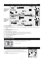
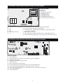
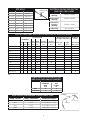
SERVICE DATA SHEET
318127078 (1003) Rev. A
Electric / Gas / Dual Fuel Slide-In Range with Electronic Oven Control
NOTICE
This service data sheet is intended for use by persons having electrical and mechanical training and a level of
knowledge of these subjects generally considered acceptable in the appliance repair trade. The manufacturer
cannot be responsible, nor assume any liability, for injury or damage of any kind arising from the use of
this data sheet.
SAFE SERVICING PRACTICES
To avoid the possibility of personal injury and/or property damage, it is important that safe servicing practices be
observed. The following are examples, but without limitation, of such practices.
1. Do not attempt a product repair if you have any doubts as to your ability to complete it in a safe and satisfactory
manner.
2. Before servicing or moving an appliance, remove power cord from electric outlet, trip circuit breaker to OFF, or
remove fuse and turn off gas supply.
3. Never interfere with the proper installation of any safety device.
4. USE ONLY REPLACEMENT PARTS CATALOGED FOR THIS APPLIANCE. SUBSTITUTIONS MAY DEFEAT COMPLIANCE
WITH SAFETY STANDARDS SET FOR HOME APPLIANCES.
5. GROUNDING: The standard color coding for safety ground wires is GREEN OR GREEN WITH YELLOW STRIPES.
Ground leads are not to be used as current carrying conductors. IT IS EXTREMELY IMPORTANT THAT THE SERVICE
TECHNICIAN REESTABLISH ALL SAFETY GROUNDS PRIOR TO COMPLETION OF SERVICE. FAILURE TO DO SO WILL
CREATE A POTENTIAL HAZARD.
6. Prior to returning the product to service, ensure that:
• All electric connections are correct and secure.
• All electrical leads are properly dressed and secured away from sharp edges, high-temperature components,
and moving parts.
• All non-insulated electrical terminals, connectors, heaters, etc. are adequately spaced away from all metal
parts and panels.
• All safety grounds (both internal and external) are correctly and securely reassembled.
• All panels are properly and securely reassembled.
ELECTRONIC OVEN CONTROL (ELECTRIC AND DUAL FUEL RANGES)
1. This self-cleaning controller offers Bake, Broil, Convection Bake, Convection Roasting and Convection Broil modes,
Dehydrating, Defrosting, Temperature Probe, Perfect Turkey, Bread Proof, Keep Warm and Cleaning functions.
2. Convection operates with an element and a fan dedicated to convection.
3. This controller includes a display board, a relay board, and a convection fan and oven light control board.
NOTE: The controllers are not field repairable. Only temperature settings can be changed. See oven calibration.
Printed in the United States
ELECTRONIC OVEN CONTROL (GAS RANGES)
1. This self-cleaning controller offers Bake, Broil, Convection Bake and Convection Roasting, Dehydrating, Defrosting,
Temperature Probe, Perfect Turkey, Bread Proof, Keep Warm and Cleaning functions.
2. Convection operates with an element and a fan dedicated to convection.
3. This controller includes a display board, a relay board, and a convection fan and oven light control board.
NOTE: The controllers are not field repairable. Only temperature settings can be changed. See oven calibration.
ELECTRONIC OVEN CONTROL RELAY BOARD FOR ELECTRIC AND DUAL FUEL RANGES
P10
P2
P18 P4
J4
P6
K6
J7
K2
J6
J5
P5
K3 K5 K7
P7
P9
P11
J2
K1
P3 P17
Relay Board Legend:
K1.Double Line Break - Upper Oven
K2.Double Line Break - Lower Oven
K3.Broil Relay - Upper Oven
K5.Bake Relay - Upper Oven
K6.Bake Relay - Lower Oven
K7.Convection Element Relay - Upper Oven
K11.Motor Door Latch - Upper Oven
K16.Cooling Fan Relay 1 - Upper Oven
K18.Cooling Fan Relay 2 - Upper Oven
K16
K11
P1
K18
J3
This relay board serves to energize the upper and lower oven heating
elements, door lock motor and cooling fan.
P1 - L2 Out, Upper Oven
P2 - L2 Out, Lower Oven
P3 - L2 In, Upper Oven
P4 - Not Used
P5 - L1, Upper Oven
P6 - L1, Lower Oven
P7 - Broil, Upper Oven
P9 - Bake, Upper Oven
P10 - Bake, Lower Oven
P11 - Convection Element, Upper Oven
P17 - Not Used
P18 - L2 In, Lower Oven
J2 - DC Power Output To Display Board
J3 - AC Power Output (motor door latch, cooling fan) For Upper Oven
J4 - Power Input (L1, Neutral)
J5 - Relay Control Inputs (bake, broil and convection elements, motor door latch, DLB) For Upper Oven
J6 - Relay Control Inputs (cooling fan) For Upper Oven
J7 - Relay Control Inputs (bake element and DLB) For
Lower Oven
2
ELECTRONIC SURFACE ELEMENT CONTROL (ESEC)
- ELECTRIC MODEL ONLY -
User Interface Board (UIB) Legend:
J2. Connector for Touch Panel LEDs and Display Indicators
J3. Connector for Touch Panel LEDs and Display Indicators
J4. Connector for Keyboard (Touch Panel)
P3.Micro Programming Header (Not Used)
P5. Connector for the hot element indicators from
Relay Board
P6.Power Supply Input (from relay board)
P7.Power Supply Input (from power supply board for
touch panel LEDs)
P9.Communication with Oven Control
P10. Surface Elements Relay Controls
User Interface Board (UIB)
ESEC Relay Board Legend:
P1.Right Front Inner Element Connection
P2.Line In (120V AC)
P3.Line In (120V AC)
P4.Right Front Outer Element Connection
P5.Left Front Inner Element Connection
P6.Line In (120V AC)
P7.Left Front Middle Element Connection
P8.Line In (120V AC)
P9.Left Front Outer Element Connection
P10. Right Rear Element Connection
P11. Line In (120V AC)
P12. Right Rear Outer Element Connection
P13. Line In (120V AC)
P14. Left Rear Element Connection
P15. Center Rear Element Connection
P16. Line In (120V AC)
P17. Not Used
ESEC Relay Board
K1. Right Front Inner Element Relay
K2. Right Front Outer Element Relay
K3. Left Front Inner Element Relay
K4. Left Front Middle Element Relay
K5. Left Front Outer Element Relay
K6. Right Rear Inner Element Relay
K7. Right Rear Outer Element Relay
K8. Left Rear Element Relay
K9. Center Rear Element Relay
J1. Line Voltage Input (120V, Neutral)
J2. Low Voltage Supply Output For UIB
J3. Surface Element Relay Control Inputs
J4. Surface Element Hot Signal Inputs
J5. Hot Element Signals to UIB
3
ELECTRONIC CONTROL DISPLAY BOARD FOR ELECTRIC AND DUAL FUEL RANGES
Electronic oven
display board
for electric
ranges
Electronic oven
display board
for dual fuel
ranges
Connector Legend:
P1 - Upper Oven Probe Input
P2 - Communication with Convection Fan and Oven Light Control Board, Communication with ESEC30 UIB (electric only)
P3 - Keyboard (touch panel)
P6 - Microprocessor Programming (not used)
P7 - Touch Panel LEDs
P8 - Power Supply Input for Display LEDs
P9 - Relay Control Output (heating elements, DLB, motor door latch) for Upper Oven
P10 - Switches Input (motor door latch switch, door switch, rack switch) for Upper Oven
P11 - Relay Control Output (heating element, DLB) for Lower Oven
P13 - Relay Control Output (cooling fan)
P16 - DC Power Supply Input
P18 - Meat Probe Input
P20 - Lower Oven Probe Input
POWER SUPPLY BOARD
This board provides power to the oven control display.
P1 - AC Power Input (L2 and Neutral)
P1
P2 - DC Power Output
P2
CONVECTION FAN AND OVEN LIGHTS CONTROL BOARD
P2
This board control the power output of the convection fan and oven lights.
P1 - Communication with display board and power supply input
P2 - AC power output for convection fan and oven lights, power inputs (L1,
neutral)
P6 - Microprocessor programming (not used)
Q4
U2
U1
U4
P1
4
Q3
P6
ELECTRONIC OVEN CONTROL RELAY BOARD FOR GAS RANGES
J4
J6
J5
P5
K3 K5 K7
P7
P9
P11
Relay Board Legend:
K3.Broil Relay
K5.Bake Relay
K7.Convection Element Relay
K11.Motor Door Latch
K16.Cooling Fan Relay 1
K18.Cooling Fan Relay 2
K19.Convection Element Relay
K20.Warmer Drawer Element Relay
J2
K11
K16
J3
K18 K19 K20
P15
This relay board serves to energize the oven heating elements, door lock motor and cooling fan.
P5 - L1
P7 - Broil
P9 - Bake
P11 - Convection Element
P15 - L1
J2 - DC Power Output To Display Control Board
J3 - AC Power Output (motor door latch, cooling fan, convection element,
warmer drawer element)
J4 - Power Input (L1, Neutral)
J5 - Relay Control Inputs (bake and broil burners, motor door latch, DLB)
J6 - Relay Control Inputs (cooling fan, conv element, warmer drawer element)
ELECTRONIC OVEN CONTROL DISPLAY BOARD FOR GAS RANGES
Connector Legend:
P1 - Oven Probe Input
P2 - Communication with Convection Fan and Oven Light Control Board
P3 - Keyboard (touch panel)
P6 - Microprocessor Programming (not used)
P7 - Touch Panel LEDs
P8 - Power Supply Input for Display LEDs
P9 - Relay Control Output (bake and broil burners, DLB, motor door latch)
P10 - Switches Input (motor door latch switch, door switch, rack switch)
P13 - Relay Control Output (cooling fans, convection element, warmer drawer element)
P16 - DC Power Supply Input
P18 - Meat Probe Input
5
CONVECTION MODE
The convection oven uses the addition of a fan and an element to heat and to move the air already in the oven.
Moving the heated air helps to destratify the heat and cause uniform heat distribution. The air is drawn in through
a fan shroud and the element located on the rear wall of the oven. It is then discharged around the outer edges of
this shroud. The air circulates around the food and then enters the shroud again. As with conventional electric wall
ovens, there is still an oven vent which discharges above the door. In preheat of non-convection cooking modes,
the convection fan will be operating until the oven has reached the target temperature.
To set the control in convection mode, follow these steps:
UPPER
1. Select upper oven by pressing UPPER OVEN OVEN .
2. Press CONVECTION BAKE
3. Press START
4. Press CANCEL
or CONVECTION ROAST
or CONVECTION BROIL
.
. The oven will automatically start and the fan will begin to run.
to stop or cancel the Convection feature at any time.
NOTE: The fan runs continuously while in the convection mode. The fan will stop if the door is opened while
convection baking/roasting/broiling. The convection element will stop operating if the door is opened.
The speed of the convection fan will vary depending on which cooking function is used. Convection Roast
uses a fast fan speed, while convection bake uses a slower fan speed.
CONVECTION FAN MOTOR
The 120V fan motor is located on the outside of the rear of the oven.
The fan motor runs continuously while in convection mode unless the door is opened.
It is normal to see the fan speed changing depending on the cooking function that is used. This appliance uses the
optimum fan speed for each convection function.
It is the Convection Fan and Oven Lights Control Board that modulates the speed of the convection fan. It uses the
fan speed information communicated by the display board.
If the fan does not operate, check the following:
- The oven control display will give you an indication on when the convection fan should be on: rotating fan blades
in the display means the fan should be ON. No rotating blades mean the convection fan is purposely not used.
- Verify proper operation of the door switch. If the control thinks the door is opened the convection fan will not
work. If the oven light turns on when the door is opened and turn off when the door is closed then it’s a good
indication the door switch is good.
- If you are getting an F23 error code it means the display board is not able to communicate with the Convection
Fan and Oven Lights Control Board, thus the convection fan will not operate. Check connections between the
display board and the Convection Fan and Oven Lights Control Board. Refer to the fault code section for corrective
actions.
- Check connections on the Convection Fan and Oven Lights Control Board. On connector P2: pin 3 should be
Neutral, pin 5 should be L1 (120VAC) and pin 7 should go to the convection fan motor. The other terminal of the
convection fan motor should be connected to Neutral.
- Fan motor coil resistance should be 15.0 ohm +/- 10%
- When the fan is ON you should see between 20 and 120VAC on the motor, depending on the fan speed.
- If there is no error code, the wiring is good and the fan coil is good then replace the Convection Fan and Oven
Lights Control Board.
OVEN CALIBRATION
Set the electronic oven control for normal baking at 350°F. Obtain an average oven temperature after a minimum
of 5 cycles.
The oven calibration can be modified using the oven control display. Please refer to the Owner's Guide manual.
Note: Changing calibration affects all the cooking modes but not the clean and the broil modes.
FIRST RISE
It is normal to see a temperature overshoot in the
first rise of all modes when you monitor the temperature.
T°
First rise overshoot
set point
t (sec)
6
ELECTRONIC OVEN CONTROL (FAULT CODES) DESCRIPTIONS
Note: Generally speaking “F1X” implies a control failure, “F3X” an oven probe problem, and “F9X” a latch motor problem.
F10 Control has sensed a potential runaway oven condition. Control may have shorted relay, RTD sensor probe may have a gone
bad. 1) Check RTD sensor probe and replace if necessary. If oven is overheating, disconnect power. If oven continues to overheat when power
is reapplied, replace relay board and/or display board.
F11 Shorted Key: a key has been detected as pressed for a long period and will be considered a shorted key alarm and will
terminate all oven activity. 1) Press any key to clear the error. 2) If fault returns, replace the keyboard (touch panel). 3) If the problem
persists, replace the display board.
F13 Control's internal checksum may have become corrupted. 1) Press any key to clear the error. 2) Disconnect power, wait 30 seconds
and reapply power. If fault returns upon power-up, replace display board.
F14 Misconnected keyboard cable. 1) Verify connection between display board and touch panel (2 ribbon cables). Make sure the cables are well
connected at both ends. 2) If the cables are good, replace the touch panel. 3) If the problem persists, replace the display board.
F15 Controller self check failed or terminal cutoff open. 1) An F15 error code on the oven controller may indicate the oven controller
is not receiving a synchronization signal from the relay board. One easy way to determine this is to power off the unit, power it on and start
a Timer for 1 minute before the F15 error code appears. If the timer counts-down normally then the synchronization signal is okay. If the
timer stays at 1:00 and does not countdown, then the synchronization signal is missing. If the synchronization signal is missing, check first
if the oven relay board is receiving 120VAC correctly (J4 pin 1 and 3). Then check the wiring between connector J2 on the relay board and
connector P16 on the oven controller. If AC power and wiring looks good and the problem is still there, replace the relay board. If problem
persists, replace the oven controller. 2) The F15 error code may be caused by an oven controller failure. If the synchronization signal has been
verified and tested good, replace the oven controller.
F20 The oven controller has detected a problem with the communication link to the surface element controller (ESEC). 1) Is the
ESEC User Interface Board powered on (are the surface element displays showing something)? If not, that is the reason why the oven control
cannot communicate with it (ESEC has no power). Check the 120VAC voltage going in to the ESEC power supply board located in the front
console (connector P1) and the low voltage supply going from the power supply board (connector P2) to the ESEC UIB (connector P8). 2)
Check connections between connector P2 on the oven controller and P9 on the ESEC User Interface Board. This is the communication link.
Verify for continuity. Refer to the wiring diagram. 3) If the above steps failed to solve the problem, replace the ESEC UIB board. 4) If problem
persists replace the oven controller.
F23 The controller failed to communicate with the convection fan and oven lights control board. 1) Verify wiring between P2 on
the display board and P2 on the convection fan and oven lights control board. 2) If wiring is good, replace convection fan and oven lights
board. 3) If the problem persists, replace the display board.
F25 No zero cross signal detected on the convection fan and oven lights control board. 1) Make sure L1 and Neutral are connected to
the convection fan and oven lights control board on connector P2 (P2 pin 3 = neutral / P2 pin 5 = L1). 2) If problem persists, replace the oven
convection fan and oven lights control board.
F30 Open RTD sensor probe/ wiring problem. Note: EOC may initially display an "F10", thinking a runaway condition exists. F31
Shorted RTD sensor probe / wiring problem. Note: F30 or F31 is displayed when oven is in active mode or an attempt to enter an
active mode is made. 1) Check wiring in probe circuit for possible open condition. 2) Check RTD resistance at room temperature (compare
to probe resistance chart). If resistance does not match the chart, replace the RTD sensor probe. 3) Let the oven cool down and restart the
function. 4) If the problem persists, replace the display board.
F90 Door motor mechanism failure. 1) Press any key to clear the error. 2) If it does not eliminate the problem, turn off power for 30
seconds, then turn on power. 3) Check wiring of Lock Motor, Lock Switch and Door Switch circuits. 4) Unplug the lock motor from the board
and apply power (L1) directly to the Lock Motor. If the motor does not rotate, replace Lock Motor Assembly. 5) Check Lock Switch for proper
operation (do they open and close, check with ohmmeter). The Lock Motor may be powered as in above step to open and close Lock Switch.
If the Lock Switch is defective, replace Motor Lock Assembly. 6) If all above steps fail to correct situation, replace the display board and/or
the relay board in the event of a motor that does not rotate. 7) If all the above steps fail to correct the situation, replace the display board in
the event of a motor that rotates endlessly.
ELECTRONIC SURFACE ELEMENT CONTROL (ESEC- some models) FAULT CODE DESCRIPTIONS
E11 Shorted Keypad. Disconnect power, wait 30 seconds and reapply power. If fault returns upon power-up: 1. Replace UIB. 2. Replace
Glass Touch Panel
E13 Bad EEPROM. Replace UIB (User Interface Board).
E14 TST/Display tail missing. Check connection between UIB (connector J2, J3 & J4) & glass touch panel. If connections are good,
replace UIB. If problem persist, replace touch panel.
E15 ESEC self test failed, or thermal cutoff open. An E15 error code on the ESEC may indicate the User Interface Board is not receiving
a synchronization signal from the ESEC relay board. Check first if the ESEC relay board is receiving 120VAC correctly (J1 pin 1 and 3). Then
check the wiring between connector J2 on the ESEC relay board and connector P6 on the UIB. If AC power and wiring looks good and the
problem is still there, replace the UIB board. If problem persists, replace the ESEC relay board.
7
OVEN
TEMPERATURE
SENSOR
RTD SCALE
Temp. °F
Temp. °C
Resistance (ohms)
32 ± 1.9
0.0 ± 1.1
1000 ± 4.0
75 ± 2.5
23.9 ± 1.4
1091 ± 5.3
250 ± 4.4 121.1 ± 2.4
1453 ± 8.9
350 ± 5.4 176.7 ± 3.0
1654 ± 10.8
450 ± 6.9 232.2 ± 3.8
1852 ± 13.5
550 ± 8.2 287.8 ± 4.6
ELECTRICAL RATING FOR ELECTRIC
AND DUAL FUEL OVENS
Bake Element
Wattage
2500W / 1879W
Broil Element
Wattage
4000W / 3004W
2047 ± 15.8
Convection
Element
Wattage
2500W / 1879W
650 ± 9.6 343.3 ± 5.3
2237 ± 18.5
KW Rating
See serial plate
900 ± 13.6 482.2 ± 7.6
2697 ± 24.4
ELECTRIC AND DUAL FUEL SLIDE-IN OVEN CIRCUIT ANALYSIS MATRIX
On Convection Fan and
Oven Lights Control Board
On Relay Board
ELEMENTS
Door DLB
Cooling
Cooling
Bake Broil Conv Motor L2 out Fan Relay 1 Fan Relay 2
P9
P7 P13 J3-5
P1
J3-7
J3-8
Bake
X
Keep Warm
X
X
X*
X
Broil
Convection Bake
X
Convection Roast
X
Bread Proof
X
Clean
X
Locking / Unlocking
X
X
X
X
X
X
X
X
X
Convection Broil
X
Conv Fan
P2-7
Light
P2-1
On Display
Board
Door Switch
P8-3 / P8-4
X*
X
X
X
X
X
X
X
X
X
X
X
X
X
X
X
X
Light
X
Door Open
X
X
Door Closed
Relay will operate in this condition only
* Convection element and fan are used for the first rise of temperature.
LOWER OVEN ON SLIDE-IN ELECTRIC
AND DUAL FUEL ANALYSIS MATRIX
Bake
Keep Warm
On Relay Board
ELEMENTS
DLB
Bake
L2 OUT
P10
P2
X
X
X
X
MEAT PROBE TEMPERATURE vs RESISTANCE TABLE
Temp. Celsius
Temp. Fahrenheit
Probe Resistance
25°C
77°F
49.478 Kohm +/- 7%
50°C
122°F
17.737 Kohm +/- 4.9%
80°C
176°F
6.107 Kohm +/- 3.3%
100°C
212°F
3.264 Kohm +/- 4.6%
8
Probe MTG Nut
Probe Receptacle
Meat Probe
EXPLODED VIEW OF CONVECTION SYSTEM
CONVECTION FAN
MOTOR ASSEMBLY
MOUNTING PLATE
OVEN CAVITY
FLAT WASHER
FAN NUT
CONVECTION
ELEMENT
CONVECTION
FAN BLADE
CONVECTION
FAN COVER
FAN COVER
SCREWS
FAN BLADE
The fan blade is mounted in the rear of the unit and has a "D" shaped mounting hole. Only minimum clearance exists between the oven back, fan blade, and fan shroud. Be careful not to bend blade when removing or installing.
Access to the fan blade is gained by removing the fan shroud, held in place by three screws, from the inside of the
oven.
The fan blade is held in place with a hex nut that has left handed threads. When removing this nut, gently hold
the fan blade, and turn the nut clockwise. If one of the blades becomes deformed, it may be bent back into shape
using a flat surface as a reference.
A flat washer is located on the motor shaft between the snap ring on the shaft and the fan blade.
NOTE: If the fan blade is bent and motor vibrations increase, the noise made by the fan will be greater.
MOUNTING PLATE OVEN
The fan motor on the rear of the unit is mounted to the main back (with three screws). There is a mounting plate
held in place between the main back (with 2 screws) and the rear oven wall (with 2 screws). Should it be necessary
to replace the oven cavity, you must remove the 2 screws located inside the unit at the rear of the oven cavity.
Cooling fan
The electronic oven control controls the cooling fan. Two relays are used but their output are tied together. Relay 2
will become active during broil, conv. broil and clean cycle at high temperature. The cooling fan is activated during
any cooking and cleaning functions. The cooling fan will also be activated whenever a surface element is in use.
9
OVEN LIGHT
This appliance is equipped with electronics that control the intensity of the oven lights. This is done with the Convection
Fan and Oven Lights Control Board that modulates the AC voltage going to the 120V halogen lamps. When the
light key is pressed or when the oven door is opened the display board communicates with the Convection Fan
and Oven Lights Control Board to specify the required light intensity. The Convection Fan and Oven Lights Control
Board also add a “theater-like” effect on the light: the light intensity is gradually ramp-up or ramp-down as the
light is turned on or off.
The lights of the upper and lower oven (warmer oven) are connected together and will turn on or off at the same
time, they cannot be controlled individually.
If the oven lights do not operate, check the following:
- If you are getting an F23 error code it means the display board is not able to communicate with the Convection Fan
and Oven Lights Control Board, thus the oven light will not operate. Check connections between the display board
and the Convection Fan and Oven Lights Control Board. Refer to the fault code section for corrective actions.
- If the lights are always ON (even with the door closed), it could be because the control mistakenly thinks the door
is opened. Verify door switch and its wiring.
- Check connections on the Convection Fan and Oven Lights Control Board. On connector P2: pin 3 should be
Neutral, pin 5 should be L1 (120VAC) and pin 1 should go to the oven lights. The other terminal of the light should
be connected to Neutral.
- Verify is light bulbs need to be replaced.
- If there is no error code, the wiring is good and still the oven lights are not working then replace the Convection
Fan and Oven Lights Control Board.
10
Block Diagram and System Interconnections
Slide-in electric and dual fuel
Oven Control 3165165xx
Power supply board 3165352xx
pin 1 = gnd
P8
pin 2 = gnd
power supply
pin 3 not used
input for control
pin 4 = V_LED2 (8.5 VDC ±2.5VDC)
board LED display
pin 5 = V_LED2 (8.5 VDC ±2.5VDC)
pin 1 = gnd
pin 2 = gnd
pin 3 not used
pin 4 = V_LED2 (8.5 VDC ±2.5VDC)
pin 5 = V_LED2 (8.5 VDC ±2.5VDC)
pin 1 = 120VAC in
P1
pin 2 not used
line voltage
pin 3 not used
input
pin 4 = neutral
P2
power supply
output
Conv Fan and Light Control upper oven 3165192xx
P2
Communication
pin 1 not used
pin 2 = Communication (0 - 5VDC)
pin 3 = gnd
pin 4 = power (5VDC ±1VDC)
pin 1 not used
pin 2 = Communication (0 - 5VDC)
pin 3 = gnd
pin 4 = power (5VDC ±1VDC)
pin 5 not used don't connect
pin 6 not used
pin 1 = upper oven probe
P1
Main Oven Probe
pin 2= upper oven probe
Main oven probe
pin 1 = lower oven probe
P20
Mini-Oven Oven
pin 2 = lower oven probe
Probe
pin 3 not used
Mini-oven probe
P18
Meat Probe
P10
Switch sense
upper oven
P2 Triac
output
pin 1 = Oven light(s) control
pin 2 not used
pin 3 = Neutral
pin 4 not used
pin 5 = L1
pin 6 not used
pin 7 = convection fan control
Oven lights
Neutral
Neutral
L1
Conv fan
Neutral
meat probe
pin 1 = meat probe
pin 2 = meat probe
pin 3 not used
pin 4 not used
pin 1 = MDL switch
pin 2 = rack sense
pin 3 = door switch
pin 4 not used
pin 5 = sense return (common)
P1
Comm and
power input
L2
Neutral
MDL switch
rack sense switch
door switch
Oven Relay Board 3164439xx
Fast-on Connectors
P16
Power supply
input for control
board
P9
Relay control
output to relay
board - main oven
all relay control:
P13
Relay control
output to relay
board - cooling
fans
all relay control:
pin 1 = gnd
pin 2 not used
pin 3 = V_UR (16 VDC ±5VDC)
pin 4 not used
pin 5 = sync signal
pin 1 = gnd
pin 2 not used
pin 3 = V_UR (16 VDC ±5VDC)
pin 4 not used
pin 5 = sync signal
pin 1 not used
pin 2 = MDL relay
pin 3 not used
pin 4 = Main Oven DLB relay
pin 5 = Main Oven Conv element relay
pin 6 = Main Oven Bake element relay
pin 7 = Main Oven Broil element relay
pin 8 not used
pin 9 = wiggler stimulus
pin 1 not used
pin 2 = MDL
pin 3 not used
J5
pin 4 = Main Oven DLB relay
Relay control
pin 5 = Main Oven Conv element relay input - main
pin 6 = Main Oven Bake element relay
oven
pin 7 = Main Oven Broil element relay
pin 8 not used
pin 9 = wiggler stimulus
pin 1 not used
pin 2 not used
pin 3 = Cooling fan relay 2
pin 4 = Cooling fan relay 1
pin 5 not used
pin 6 not used
pin 7 not used
pin 8 = PWM relays
pin 1 not used
pin 2 not used
pin 3 = Cooling fan relay 2
pin 4 = Cooling fan relay 1
pin 5 not used
pin 6 not used
pin 7 not used
pin 8 = PWM relays
J6
Relay control
input - cooling
fans
pin 1 not used
pin 2 = mini-oven Bake element relay
pin 3 not used
pin 4 = mini-oven DLB relay
pin 5 not used
pin 6 not used
pin 7 not used
J7
Relay control
input- minioven
3.3VDC = relay closed. 0V = relay open
3.3VDC = relay closed. 0V = relay open
pin 1 not used
pin 2 = mini-oven Bake element relay
P11
pin 3 not used
Relay control
pin 4 = mini-oven DLB relay
output to relay
pin 5 not used
board - mini-oven
pin 6 not used
pin 7 not used
all relay control: 3.3VDC = relay closed. 0V = relay open
P3 (20 pins)
Keyboard
P7 (30 pins)
Touch panel LEDs
J2
Power supply
output
(L2 in )
(L2 out)
L2 in )
(L2 out
J3
120VAC
output for
MDL and
cooling fan
Main oven
P5
P9
P7
P11
P3
P1
L1
Upper Bake element
Upper Broil element
Upper Conv element
L2
P6
P10
L1
mini-oven Bake element
P18
P2
L2
pin 1 = Neutral
pin 2 not used
pin 3 = L1
pin 4 not used
pin 5 = MDL
pin 6 not used
pin 7 = Cooling fan 1
pin 8 = Cooling fan 2
Neutral
L1
MDL
Cooling fan
J4
pin 1 = Neutral
120VAC pin 2 not used
input for pin 3 = L1
transformer
Neutral
L1
Glass Touch panel
ESEC20/30 relay board 3164421xx
ESEC30 UIB 3165166xx
slide-in electric only
P9
Communication
pin 1 = LIN comm
pin 2 not used
pin 3 = gnd
pin 1 = LR hot surface
pin 2 = LF hot surface
pin 3 = center hot surface
P5
pin 4 = RR hot surface
hot surface sense
pin 5 = RF hot surface
pin 6 not used
pin 7 = return path all hot surface
P10
Relay control
output
Relay control:
P6
Power supply
input from relay
board
slide-in electric only
J4
hot surface sense (from elements)
pin 1 = LR hot surface
pin 2 = LF hot surface
pin 3 = center hot surface
pin 4 = RR hot surface
pin 5 = RF hot surface
pin 6 not used
pin 7 = return path all hot surface
pin 1 = PWM relays
pin 2 not used
pin 3 = wiggler stimulus
pin 4 = K1 relay (RF inner)
pin 5 = K2 relay (RF outer)
pin 6 = K3 relay (LF inner)
pin 7 = K4 relay (LF middle)
pin 8 = K5 relay (LF outer)
pin 9 = K6 relay (RR inner)
pin 10 = K7 relay (RR outer)
pin 11 = K8 relay (LR)
pin 12 = K9 relay (CR)
pin 1 = gnd
pin 2 not used
pin 3 = V_UR (16 VDC ±5VDC)
pin 4 not used
pin 1 = gnd
pin 2 not used
pin 3 = V_UR (16 VDC ±5VDC)
pin 4 not used
pin 5 = sync signal
pin 5 = sync signal
5VDC = relay closed. 0V = relay open
pin 1 = LR hot surface
LR limitor
pin 2 = LF hot surface
pin 3 = center hot surface
pin 4 = RR hot surface
pin 5 = RF hot surface
pin 6 not used
pin 7 = common all hot surface
LF limitor
center limitor
RR limitor
RF limitor
Surface elements connections:
P1
RF-1
P2
LINE IN
P3
LINE IN
P4
RF-2
P5
LF-1
P6
LINE IN
P7
LF-2
J5
hot surface to
UIB
P8
P9
P10
P11
P12
P13
P14
P15
P16
P17
J3
Relay control
input
LINE IN
LF-3
RR-1
LINE IN
RR-2
LINE IN
LR
CR
LINE IN
N/C
J2
Power supply
output
J1
120VAC input
pin 1 = neutral
pin 2 not used
pin 3 = L2
Neutral
L2
Power supply board 3165352xx
pin 1 = gnd
P7
pin 2 = gnd
extra power
pin 3 not used
supply for LEDs pin 4 = V_LED2 (8.5 VDC ±2.5VDC)
pin 5 = V_LED2 (8.5 VDC ±2.5VDC)
pin 1 = gnd
pin 2 = gnd
pin 3 not used
pin 4 = V_LED2 (8.5 VDC ±2.5VDC)
pin 5 = V_LED2 (8.5 VDC ±2.5VDC)
pin 1 = L2
P1
pin 2 & 3 not used
line voltage pin 4 = neutral
input
P2
power supply
output
11
L2
Neutral
Neutral
Block Diagram and System Interconnections
Slide-in gas
Oven Control 3165165xx
Power supply board 3165352xx
pin 1 = gnd
P8
pin 2 = gnd
power supply
pin 3 not used
input for control
pin 4 = V_LED2 (8.5 VDC ±2.5VDC)
board LED display
pin 5 = V_LED2 (8.5 VDC ±2.5VDC)
pin 1 = gnd
pin 2 = gnd
pin 3 not used
pin 4 = V_LED2 (8.5 VDC ±2.5VDC)
pin 5 = V_LED2 (8.5 VDC ±2.5VDC)
P2
power supply
output
pin 1 = 120VAC in
P1
pin 2 not used
line voltage
pin 3 not used
input
pin 4 = neutral
Conv Fan and Light Control upper oven 3165192xx
P2
Communication
P1
Oven Probe
P18
Meat Probe
P10
Switch sense
pin 1 not used
pin 1 not used
pin 2 = Communication (0 - 5VDC)
pin 2 = Communication (0 - 5VDC)
pin 3 = gnd
pin 4 = power (5VDC ±1VDC)
pin 1 = oven probe
pin 3 = gnd
pin 4 = power (5VDC ±1VDC)
pin 5 not used don't connect
pin 6 not used
P1
Comm and
power input
P2 Triac
output
L2
Neutral
pin 1 = Oven light(s) control
pin 2 not used
pin 3 = Neutral
pin 4 not used
pin 5 = L1
pin 6 not used
pin 7 = convection fan control
Oven lights
Neutral
Neutral
L1
Conv fan
Neutral
oven probe
pin 2 = oven probe
pin 1 = meat probe
pin 2 = meat probe
pin 3 not used
pin 4 not used
pin 1 = MDL switch
pin 2 = rack sense
pin 3 = door switch
pin 4 = warmer drawer thermostat
pin 5 = sense return (common)
meat probe
MDL switch
rack sense switch
door switch
warmer drawer thermostat
Oven Relay Board 3164439xx
Fast-on Connectors
pin 1 = gnd
P16
pin 2 = V_LED (8.5 VDC ±2.5VDC)
Power supply
pin 3 = V_UR (16 VDC ±5VDC)
input for control
pin 4 not used
board
pin 5 = sync signal
P9
Relay control
output to relay
board
pin 1 = gnd
pin 2 = V_LED (8.5 VDC ±2.5VDC)
pin 3 = V_UR (16 VDC ±5VDC)
pin 4 not used
pin 5 = sync signal
J2
Power supply
output
pin 1 not used
pin 2 = MDL relay
pin 3 not used
pin 4 not used
pin 5 not used
pin 6 = Bake burner relay
pin 7 = Broil burner relay
pin 8 not used
pin 9 = wiggler stimulus
pin 1 not used
pin 2 = MDL
pin 3 not used
pin 4 not used
pin 5 not used
pin 6 = Bake burner relay
pin 7 = Broil burner relay
pin 8 not used
pin 9 = wiggler stimulus
J5
Relay control
input
pin 1 not used
pin 2 = Convection element relay
pin 3 = Cooling fan relay 2
pin 4 = Cooling fan relay 1
pin 5 not used
pin 6 not used
pin 7 = Warmer drawer element relay
pin 8 = PWM relays
pin 1 not used
pin 2 = Convection element relay
pin 3 = Cooling fan relay 2
pin 4 = Cooling fan relay 1
pin 5 not used
pin 6 not used
pin 7 = Warmer drawer element relay
pin 8 = PWM relays
J6
Relay control
input
all relay control: 3.3VDC = relay closed. 0V = relay open
P13
Relay control
output to relay
board
all relay control: 3.3VDC = relay closed. 0V = relay open
J3
120VAC
output for
MDL and
cooling fan
Glass Touch panel
12
L1
P15
L1
pin 1 = Neutral
pin 2 not used
pin 3 = L1
pin 4 not used
pin 5 = MDL
pin 6 not used
pin 7 = Cooling fan 1
pin 8 = Cooling fan 2
pin 9 = warmer drawer element
pin 10 = convection element
J4
pin 1 = Neutral
120VAC pin 2 not used
input for pin 3 = L1
transformer
P3 (20 pins)
Keyboard
P7 (30 pins)
Touch panel LEDs
P5
P9
P7
Bake burner
Broil burner
Neutral
MDL
Neutral
Neutral
L1
Cooling fan
Warmer Drawer element
Conv element
Neutral
L1