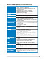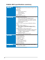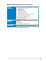
1
Motherboard
M2R32-MVP
E2717
First Edition V1
July 2006
Copyright © 2006 ASUSTeK COMPUTER INC. All Rights Reserved.
No part of this manual, including the products and software described in it, may be reproduced,
transmitted, transcribed, stored in a retrieval system, or translated into any language in any form
or by any means, except documentation kept by the purchaser for backup purposes, without the
express written permission of ASUSTeK COMPUTER INC. (“ASUS”).
Product warranty or service will not be extended if: (1) the product is repaired, modified or
altered, unless such repair, modification of alteration is authorized in writing by ASUS; or (2) the
serial number of the product is defaced or missing.
ASUS PROVIDES THIS MANUAL “AS IS” WITHOUT WARRANTY OF ANY KIND, EITHER EXPRESS OR
IMPLIED, INCLUDING BUT NOT LIMITED TO THE IMPLIED WARRANTIES OR CONDITIONS OF
MERCHANTABILITY OR FITNESS FOR A PARTICULAR PURPOSE. IN NO EVENT SHALL ASUS, ITS
DIRECTORS, OFFICERS, EMPLOYEES OR AGENTS BE LIABLE FOR ANY INDIRECT, SPECIAL,
INCIDENTAL, OR CONSEQUENTIAL DAMAGES (INCLUDING DAMAGES FOR LOSS OF PROFITS, LOSS
OF BUSINESS, LOSS OF USE OR DATA, INTERRUPTION OF BUSINESS AND THE LIKE), EVEN IF ASUS
HAS BEEN ADVISED OF THE POSSIBILITY OF SUCH DAMAGES ARISING FROM ANY DEFECT OR
ERROR IN THIS MANUAL OR PRODUCT.
SPECIFICATIONS AND INFORMATION CONTAINED IN THIS MANUAL ARE FURNISHED FOR
INFORMATIONAL USE ONLY, AND ARE SUBJECT TO CHANGE AT ANY TIME WITHOUT NOTICE, AND
SHOULD NOT BE CONSTRUED AS A COMMITMENT BY ASUS. ASUS ASSUMES NO RESPONSIBILITY
OR LIABILITY FOR ANY ERRORS OR INACCURACIES THAT MAY APPEAR IN THIS MANUAL,
INCLUDING THE PRODUCTS AND SOFTWARE DESCRIBED IN IT.
Products and corporate names appearing in this manual may or may not be registered
trademarks or copyrights of their respective companies, and are used only for identification or
explanation and to the owners’ benefit, without intent to infringe.
ii
Contents
Notices ............................................................................................... vii
Safety information ............................................................................ viii
About this guide ................................................................................. ix
M2R32-MVP specifications summary .................................................. xi
Chapter 1:
Product introduction
1.1
Welcome! .............................................................................. 1-1
1.2
Package contents ................................................................. 1-1
1.3
Special features .................................................................... 1-2
1.3.1
Product highlights ................................................... 1-2
1.3.2
Innovative ASUS features ....................................... 1-4
Chapter 2:
Hardware information
2.1
Before you proceed .............................................................. 2-1
2.2
Motherboard overview .......................................................... 2-2
2.3
2.4
2.5
2.2.1
Placement direction ................................................ 2-2
2.2.2
Screw holes ............................................................ 2-2
2.2.3
Motherboard layout ................................................ 2-3
2.2.4
Layout Contents ..................................................... 2-4
Central Processing Unit (CPU) .............................................. 2-6
2.3.1
Installing the CPU .................................................... 2-6
2.3.2
Installing the heatsink and fan ................................ 2-8
System memory ................................................................. 2-11
2.4.1
Overview ............................................................... 2-11
2.4.2
Memory Configurations ......................................... 2-12
2.4.3
Installing a DDR2 DIMM ......................................... 2-14
2.4.4
Removing a DDR2 DIMM ........................................ 2-14
Expansion slots ................................................................... 2-15
2.5.1
Installing an expansion card .................................. 2-15
2.5.2
Configuring an expansion card .............................. 2-15
2.5.3
Interrupt assignments .......................................... 2-16
2.5.4
Two PCI slots ........................................................ 2-17
2.5.5
Two PCI Express x1 slots ...................................... 2-17
2.5.6
Two PCI Express x16 slots ................................... 2-17
iii
Contents
2.6
Jumper ............................................................................... 2-19
2.7
Connectors ......................................................................... 2-22
2.7.1
Rear panel connectors .......................................... 2-22
2.7.2
Internal connectors ............................................... 2-24
Chapter 3:
iv
Powering up
3.1
Starting up for the first time ................................................ 3-1
3.2
Powering off the computer .................................................. 3-2
3.2.1
Using the OS shut down function ........................... 3-2
3.2.2
Using the dual function power switch .................... 3-2
Notices
Federal Communications Commission Statement
This device complies with Part 15 of the FCC Rules. Operation is subject to
the following two conditions:
• This device may not cause harmful interference, and
• This device must accept any interference received including interference
that may cause undesired operation.
This equipment has been tested and found to comply with the limits for a
Class B digital device, pursuant to Part 15 of the FCC Rules. These limits are
designed to provide reasonable protection against harmful interference in a
residential installation. This equipment generates, uses and can radiate radio
frequency energy and, if not installed and used in accordance with
manufacturer’s instructions, may cause harmful interference to radio
communications. However, there is no guarantee that interference will not
occur in a particular installation. If this equipment does cause harmful
interference to radio or television reception, which can be determined by
turning the equipment off and on, the user is encouraged to try to correct
the interference by one or more of the following measures:
• Reorient or relocate the receiving antenna.
• Increase the separation between the equipment and receiver.
• Connect the equipment to an outlet on a circuit different from that to
which the receiver is connected.
• Consult the dealer or an experienced radio/TV technician for help.
The use of shielded cables for connection of the monitor to the graphics
card is required to assure compliance with FCC regulations. Changes or
modifications to this unit not expressly approved by the party
responsible for compliance could void the user’s authority to operate
this equipment.
Canadian Department of Communications Statement
This digital apparatus does not exceed the Class B limits for radio noise
emissions from digital apparatus set out in the Radio Interference
Regulations of the Canadian Department of Communications.
This class B digital apparatus complies with Canadian
ICES-003.
v
Safety information
Electrical safety
• To prevent electrical shock hazard, disconnect the power cable from
the electrical outlet before relocating the system.
• When adding or removing devices to or from the system, ensure that
the power cables for the devices are unplugged before the signal cables
are connected. If possible, disconnect all power cables from the existing
system before you add a device.
• Before connecting or removing signal cables from the motherboard,
ensure that all power cables are unplugged.
• Seek professional assistance before using an adapter or extension cord.
These devices could interrupt the grounding circuit.
• Make sure that your power supply is set to the correct voltage in your
area. If you are not sure about the voltage of the electrical outlet you
are using, contact your local power company.
• If the power supply is broken, do not try to fix it by yourself. Contact a
qualified service technician or your retailer.
Operation safety
• Before installing the motherboard and adding devices on it, carefully read
all the manuals that came with the package.
• Before using the product, make sure all cables are correctly connected
and the power cables are not damaged. If you detect any damage,
contact your dealer immediately.
• To avoid short circuits, keep paper clips, screws, and staples away from
connectors, slots, sockets and circuitry.
• Avoid dust, humidity, and temperature extremes. Do not place the
product in any area where it may become wet.
• Place the product on a stable surface.
• If you encounter technical problems with the product, contact a qualified
service technician or your retailer.
The symbol of the crossed out wheeled bin indicates that the product
(electrical and electronic equipment) should not be placed in municipal
waste. Please check local regulations for disposal of electronic products.
vi
About this guide
This user guide contains the information you need when installing and
configuring the motherboard.
How this guide is organized
This guide contains the following parts:
•
Chapter 1: Product introduction
This chapter describes the features of the motherboard and the new
technology it supports.
•
Chapter 2: Hardware information
This chapter lists the hardware setup procedures that you have to
perform when installing system components. It includes description of
the switches, jumpers, and connectors on the motherboard.
•
Chapter 3: Powering up
This chapter describes the power up sequence, the vocal POST
messages, and ways of shutting down the system.
Where to find more information
Refer to the following sources for additional information and for product
and software updates.
1.
ASUS websites
The ASUS website provides updated information on ASUS hardware
and software products. Refer to the ASUS contact information.
2.
Optional documentation
Your product package may include optional documentation, such as
warranty flyers, that may have been added by your dealer. These
documents are not part of the standard package.
vii
Conventions used in this guide
To make sure that you perform certain tasks properly, take note of the
following symbols used throughout this manual.
D A N G E R / W A R N I N G : Information to prevent injury to yourself
when trying to complete a task.
C A U T I O N : Information to prevent damage to the components
when trying to complete a task.
I M P O R T A N T : Instructions that you MUST follow to complete a
task.
N O T E : Tips and additional information to help you complete a
task.
Typography
Bold text
Indicates a menu or an item to select.
Italics
Used to emphasize a word or a phrase.
<Key>
Keys enclosed in the less-than and greater-than sign means
that you must press the enclosed key.
Example: <Enter> means that you must press the Enter or
Return key.
<Key1+Key2+Key3>
If you must press two or more keys simultaneously, the
key names are linked with a plus sign (+).
Example: <Ctrl+Alt+D>
Command
Means that you must type the command exactly as shown,
then supply the required item or value enclosed in
brackets.
Example: At the DOS prompt, type the command line:
afudos /i[filename]
afudos /iM2R32-MVP.ROM
viii
M2R32-MVP specifications summary
CPU
Socket AM2 for AMD Athlon™ 64 X2/Athlon™ 64 FX/
Athlon™ 64/Sempron™ processor
AMD64 architecture enables simultaneous 32- and
64-bit computing
Supports AMD Cool ‘n’ Quiet™ Technology
Supports AMD HyperTransport™ Technology
Supports AMD Live!™ Ready
Chipset
ATI™ CrossFire™ Xpress 3200/ATI™ SB600
System bus
2000/1600 MT/s
Memory
Dual-channel memory architecture
4 x 240-pin DIMM sockets support up to 8 GB
unbufferred ECC/non-ECC 800/667/533 MHz DDR2
memory modules
Expansion slots
2 x PCI Express™ x16 slots with CrossFire support at full
x16, x16 mode
2 x PCI Express™ x1 slots
2 x PCI slots
CrossFire™
Supports ATI CrossFire™ graphics cards (both at x16
mode)
Storage
ATI SB600 Southbridge supports:
- 1 x IDE connector for two Ultra DMA
133/100/66/33 hard disks
- 4 x Serial ATA I/II 3.0 Gb/s hard disks with RAID 0,
RAID 1, and RAID 0+1
JMicron® 360 SATA controller supports:
- 1 x External Serial ATA 3.0Gb/s hard disk (SATA Onthe-Go)
High Definition
Audio
SoundMAX® ADI 1988A 8-channel High Definition Audio
CODEC
Supports Multi-streaming and Universal Audio Jack
Coaxial S/PDIF Out port on the rear panel
LAN
Marvell® 88E8001 Gigabit LAN controller, featuring
AI NET2
IEEE 1394a
VIA VT6308P controller supports:
- 1 x IEEE 1394a connector at mid-board
- 1 x IEEE 1394a connector at rear-board
USB
Supports up to 10 USB 2.0/1.1 ports
BIOS features
8 Mb Flash ROM, AMI BIOS, PnP, DMI2.0, SM BIOS 2.3,
WfM2.0
(continued on the next page)
ix
M2R32-MVP specifications summary
ASUS special
features
Stack Cool 2
ASUS SATA On-the-Go (External Serial ATA port on the
rear panel)
Noise Filter
ASUS EZ DIY:
- ASUS CrashFree BIOS 3
- ASUS EZ Flash 2
- ASUS Q-Connector
ASUS MyLogo2
ASUS Q-Fan2 Technology
Overclocking
Intelligent overclocking tools:
- AI NOS™ (Non-delay Overclocking System)
- AI Overclocking (intelligent CPU frequency tuner)
- ASUS PEG Link (automatic performance tuning for
single/dual graphics cards)
- AI Clock Skew
ASUS O.C. Profile: overclocking configuration-sharing
tool
Precision Tweaker supports:
- DIMM voltage: 12-step DRAM voltage control
- Core voltage: Adjustable CPU voltage at 0.025 V
increment
Stepless Frequency Selection(SFS) allows:
- FSB tuning from 200 MHz to 400 MHz at 1 MHz increment
- PCI Express frequency tuning from 100 MHz to
150 MHz at 1 MHz increment
Overclocking protection:
- ASUS C.P.R. (CPU Parameter Recall)
Rear panel
1 x PS/2 mouse port
1 x PS/2 keyboard port
1 x LAN (RJ-45) port
4 x USB 2.0/1.1 ports
1 x IEEE1394a port
1 x Coaxial S/PDIF Out port
1 x External Serial ATA port
1 x Serial (COM) port
8-Channel audio ports
Manageabiity
WfM 2.0, DMI 2.0, WOL by PME, WOR by PME, Chassis
Intrusion, PXE, and RPL
(continued on the next page)
x
M2R32-MVP specifications summary
Internal
connectors
3 x USB 2.0 connectors for six additional USB 2.0 ports
1 x Floppy disk drive connector
1 x IDE connector
4 x SATA connectors
1 x IEEE1394a connector
1 x CD audio in connector
1 x S/PDIF Out connector
1x CPU/2 x Chassis/1 x Power fan connectors
1 x 24-pin EATX power connector
1 x 4-pin ATX 12 V power connector
Chassis intrusion connector
Front panel High Definition Audio connector
System panel connector
Support CD
contents
Drivers
ASUS PC Probe II
ASUS Update
Anti-virus software (OEM version)
Form factor
ATX form factor: 12 in x 9.6 in (30.5 cm x 24.5 cm)
*Specifications are subject to change without notice.
xi
xii
This chapter describes the
motherboard features and the new
technologies it supports
1
Product
information
Chapter summary
1
1.1
Welcome! .............................................................................. 1-1
1.2
Package contents ................................................................. 1-1
1.3
Special features .................................................................... 1-2
ASUS A8R32-MVP DELUXE
1.1
Welcome!
T h a n k y o u f o r b u y i n g a n A S U S® M 2 R 3 2 - M V P m o t h e r b o a r d !
The motherboard delivers a host of new features and latest technologies,
making it another standout in the long line of ASUS quality motherboards!
Before you start installing the motherboard, and hardware devices on it,
check the items in your package with the list below.
1.2
Package contents
Check your motherboard package for the following items.
Motherboard
ASUS M2R32-MVP motherboard
Cables
1 x Floppy disk drive signal cable
1 x Ultra DMA cable 133/100/66 cable
2 x Serial ATA cables
1 x 2-port Serial ATA power cable
1 x 2-port USB 2.0 module
Accessories
I/O shield
1 x ASUS Q-Connector set (USB, IEEE1394a, system
panel; retail version only)
Application CDs
ASUS motherboard support CD
Documentation
User guide
If any of the above items is damaged or missing, contact your retailer.
ASUS M2R32-MVP
1-1
1.3
Special features
1.3.1
Product highlights
Latest processor technology
The motherboard supports AMD socket AM2 single-core Athlon 64/
Sempron and dual-core Athlon 64 X2/Athlon 64 FX processors with 2MB/
1MB/512KB L2 cache, which is based on 64-bit architecture. It features
2000/1600 MT/s HyperTransport Bus, dual-channel un-buffered DDR2 800
memory support and AMD Cool ‘n’ Quiet Technology. See page 2-6 for
details.
ATI CrossFire™ Xpress 3200
The motherboard features ATI CrossFire™ Xpress 3200 support, delivering
improved overclocking and optimal PCI Express device performance. The
combined multi-GPU power boosts image quality and rendering speed for
the highest quality images. With its optimized peer-to-peer and general link
performance GPU sharing, you are a step ahead in graphics and gaming
effects. The chipset allows higher antialiasing, anisotropic filtering, sharing,
and texture settings. The ATI CrossFire™ Xpress 3200 also comes with the
ATI Catalyst™ Control Center that allows you to get real-time 3D-rendered
previews of adjustments to your display configurations and advanced 3D
settings.
PCI Express™ interface
The motherboard fully supports PCI Express, the latest I/O interconnect
technology that speeds up the PCI bus. PCI Express features point-to-point
serial interconnections between devices and allows higher clockspeeds by
carrying data in packets. This high speed interface is software compatible
with existing PCI specifications. See page 2-18 for details.
Gigabit LAN solution
The motherboard comes with the Marvell® 88E8001 Gigabit LAN controller
to provide the total solution for your networking needs, LAN, and file
sharing requirements. See page 2-23 for details.
1-2
Chapter 1: Product introduction
Serial ATA 3.0 Gb/s technology and SATA-On-The-Go
The motherboard fully supports the Serial ATA II 3.0 Gb/s technology
through the Serial ATA interfaces and the ATI® SB 600 chipset. The Serial
ATA 3.0 Gb/s specification provides twice the bandwidth of the current
Serial ATA products with a host of new features, including Power
Management (PM) Implementation Algorithm. Serial ATA allows for thinner,
more flexible cables with lower pin count and reduced voltage required.
Leveraging these Serial ATA 3.0 Gb/s features is the SATA-On-The-Go.
Supported by the JMicron® Serial ATA controller, the Serial ATA 3.0 Gb/s
connector (on the rear panel) provides smart setup and hot-plug function.
See pages 2-24 and 2-26 for details.
8-channel high definition audio
Onboard is the ADI® AD1988A High Definition Audio 8-channel audio
CODEC. This CODEC is fully-compliant with Intel® High Definition Audio
standard (192 KHz, 24-bit audio). With the CODEC, 8-channel audio ports,
and S/PDIF interfaces, you can connect your computer to home theater
decoders to produce crystal-clear digital audio.
IEEE 1394a support
The IEEE 1394a interface provides high-speed and flexible PC connectivity
to a wide range of peripherals and devices compliant to IEEE 1394a
standards. The IEEE 1394a interface allows up to 400 Mbps transfer rates
through simple, low-cost, high-bandwidth asynchronous (real-time) data
interfacing between computers, peripherals, and consumer electronic
devices such as camcorders, VCRs, printers,TVs, and digital cameras. See
page 2-30 for details.
USB 2.0 technology
The motherboard implements the Universal Serial Bus (USB) 2.0
specification, dramatically increasing the connection speed from the
12 Mbps bandwidth on USB 1.1 to a fast 480 Mbps on USB 2.0. USB 2.0 is
backward compatible with USB 1.1. See pages 2-24 and 2-29 for details.
ASUS M2R32-MVP
1-3
1.3.2
Innovative ASUS features
ASUS Stack Cool 2
ASUS Stack Cool 2 is a fan-less and zero-noise cooling solution that lowers
the temperature of critical heat generating components. The motherboard
uses a special design on the printed circuit board (PCB) to dissipate heat
that critical components generate.
AI NET2
The AI NET2 is a BIOS-based diagnostic tool that detects and reports
Ethernet cable faults and shorts. With this utility, you can easily monitor
the condition of the Ethernet cable(s) connected to the LAN (RJ-45)
port(s). During the bootup process, AI NET2 immediately diagnoses the
LAN cable(s) and reports shorts and faults up to 100 meters at 1 meter
accuracy.
Precision Tweaker
This feature allows you to fine tune the CPU/memory/Northbridge voltage
and gradually increase the memory Front Side Bus (FSB) and PCI Express
frequency at 1MHz increment to achieve maximum system performance.
AI NOS™ (Non-Delay Overclocking System)
ASUS Non-delay Overclocking System™ (NOS) is a technology that
auto-detects the CPU loading and dynamically overclocks the CPU speed
only when needed. See page 4-19 for details.
Noise Filter
This feature detects repetitive and stationary noises (non-voice signals)
like computer fans, air conditioners, and other background noises then
eliminates it in the incoming audio stream while recording.
1-4
Chapter 1: Product introduction
PEG Link Mode for two graphics cards
This feature enhances your PCI Express graphics card performance, allowing
the motherboard to automatically adjust the PCI Express graphics link mode
to the correct frequency based on the system configuration. Four
additional settings are available for overclocking the PEG Link Mode.
ASUS Q-Fan 2 technology
The ASUS Q-Fan 2 technology smartly adjusts the CPU and chassis fans
speed according to the system loading to ensure quiet, cool, and efficient
operation.
ASUS CrashFree BIOS 3
The ASUS CrashFree BIOS 3 allows users to restore corrupted BIOS data
from a USB flash disk containing the BIOS file. This utility saves users the
cost and hassle of buying a replacement BIOS chip.
ASUS EZ Flash 2
EZ Flash 2 is a user-friendly BIOS update utility. Simply press the predefined
hotkey to launch the utility and update the BIOS without entering the OS.
Update your BIOS easily without preparing a bootable diskette or using an
OS-based flash utility.
Q-Connector
The ASUS Q-Connector allows you to connect or disconnect chassis front
panel cables in one easy step with one complete module. This unique
adapter eliminates the trouble of plugging in one cable at a time, making
connection quick and accurate.
ASUS O.C. Profile
The motherboard features the ASUS BIOS Profile that allows users to
conveniently store or load multiple BIOS settings. The BIOS settings can be
stored in the CMOS or a separate file, giving users freedom to share and
distribute their favorite settings.
ASUS M2R32-MVP
1-5
ASUS Multi-language BIOS
The multi-language BIOS allows you to select the language of your choice
from the available options. The localized BIOS menus allow easier and faster
configuration.
ASUS MyLogo2™
ASUS My Logo2™ is the new feature present in the motherboard that
allows you to personalize and add style to your system with customizable
and animated boot logos.
C.P.R. (CPU Parameter Recall)
The C.P.R. feature of the motherboard BIOS allows automatic re-setting to
the BIOS default settings in case the system hangs due to overclocking.
When the system hangs due to overclocking, C.P.R. eliminates the need to
open the system chassis and clear the RTC data. Simply shut down and
reboot the system, and the BIOS automatically restores the CPU default
setting for each parameter.
1-6
Chapter 1: Product introduction
This chapter lists the hardware setup
procedures that you have to perform
when installing system components.
It includes description of the jumpers
and connectors on the motherboard.
2
Hardware
information
Chapter summary
2
2.1
Before you proceed .............................................................. 2-1
2.2
Motherboard overview .......................................................... 2-2
2.3
Central Processing Unit (CPU) .............................................. 2-6
2.4
System memory ................................................................. 2-11
2.5
Expansion slots ................................................................... 2-15
2.6
Jumper ............................................................................... 2-19
2.7
Connectors ......................................................................... 2-22
ASUS M2R32-MVP
2.1
Before you proceed
Take note of the following precautions before you install motherboard
components or change any motherboard settings.
•
Unplug the power cord from the wall socket before touching any
component.
•
Use a grounded wrist strap or touch a safely grounded object or a
metal object, such as the power supply case, before handling
components to avoid damaging them due to static electricity
•
Hold components by the edges to avoid touching the ICs on them.
•
Whenever you uninstall any component, place it on a grounded
antistatic pad or in the bag that came with the component.
•
Before you install or remove any component, ensure
that the ATX power supply is switched off or the
p o w e r c o r d i s d e t a c h e d f r o m t h e p o w e r s u p p l y . Failure
to do so may cause severe damage to the motherboard, peripherals,
and/or components.
Onboard LED
®
The motherboard comes with a standby power LED that lights up to
indicate that the system is ON, in sleep mode, or in soft-off mode.
This is a reminder that you should shut down the system and unplug
the power cable before removing or plugging in any motherboard
component. The illustration below shows the location of the onboard
LED.
SB_PWR
M2R32-MVP
M2R32-MVP Onboard LED
ASUS M2R32-MVP
ON
Standby
Power
OFF
Powered
Off
2-1
2.2
Motherboard overview
Before you install the motherboard, study the configuration of your chassis
to ensure that the motherboard fits into it. Refer to the chassis
documentation before installing the motherboard.
Make sure to unplug the power cord before installing or removing the
motherboard. Failure to do so can cause you physical injury and damage
motherboard components.
2.2.1
Placement direction
When installing the motherboard, make sure that you place it into the
chassis in the correct orientation. The edge with external ports goes to the
rear part of the chassis as indicated in the image below.
2.2.2
Screw holes
Place nine (9) screws into the holes indicated by circles to secure the
motherboard to the chassis.
®
Do not overtighten the screws! Doing so can damage the motherboard.
Place this side towards
the rear of the chassis
M2R32-MVP
2-2
Chapter 2: Hardware information
2.2.3
Motherboard layout
24.5cm (9.6in)
KBPWR1
PS/2KBMS
T: Mouse
B: Keyboard
DDR2 DIMM_B2 (64 bit,240-pin module)
COM1
CHA_FAN2
DDR2 DIMM_A2 (64 bit,240-pin module)
CPU_FAN
ESATA
USBPW12
USBPW34
DDR2 DIMM_B1 (64 bit,240-pin module)
DDR2 DIMM_A1 (64 bit,240-pin module)
JMB360
PRI_IDE
Socket AM2
LAN_USB34
30.5cm (12.0in)
AUDIO
EATXPWR
®
F_USB12
SPDIF_OUT
SPDIF_O1
ATX12V
USB910
PWR_FAN
PCIEX16_1
CD
PCIEX1_1
CHA_FAN1
AD1988A
PCIEX1_2
PCIEX16_2
M2R32-MVP
VIA
VT6308P
PCI2
CHASSIS
USBPW56
USBPW78
PCI1
Marvell
88E8001
USB56
AAFP
IE1394_2
ASUS M2R32-MVP
CR2032 3V
Lithium Cell
CMOS Power
CLRTC
iTE
IT8726F-S
8Mb
BIOS
FLOPPY
SB_PWR
SATA2 SATA1
SATA4 SATA3
USBPW910
PANEL
USB78
2-3
2.2.4
2-4
Layout Contents
Slots
Page
1.
DDR DIMM slots
2-11
2.
PCI slots
2-17
3.
PCI Express x1 slots
2-17
4.
PCI Express x16 slots
2-17
Jumper
Page
1.
Clear RTC RAM (3-pin CLRTC)
2-19
2.
USB device wake-up (3-pin USBPW12, USBPW34, USBPW56,
USBPW78, USBPW910)
2-20
3.
Keyboard power (3-pin KBPWR1)
2-21
Rear panel connectors
Page
1.
2-22
PS/2 mouse port (green)
2.
IEEEa 1394 port
2-22
3.
LAN (RJ-45) port
2-22
4.
Rear Speaker Out port (black)
2-22
5.
Center/Subwoofer port (orange)
2-22
6.
Line In port (light blue)
2-22
7.
Line Out port (lime)
2-22
8.
Coaxial S/PDIF Out port
2-23
9.
Microphone port (pink)
2-23
10. Side Speaker Out port (gray)
2-23
11. USB 2.0 ports 3 and 4
2-23
12. USB 2.0 ports 1 and 2
2-23
13. External SATA port
2-23
14. Serial (COM) port
2-23
15. PS/2 keyboard port (purple)
2-23
Chapter 2: Hardware information
Internal connectors
Page
1.
Floppy disk drive connector (34-1 pin FLOPPY)
2-24
2.
IDE connectors (40-1 pin PRI_IDE)
2-24
3.
Serial ATA connectors (7-pin SATA1, SATA2, SATA3, SATA4)
2-25
4.
CPU, Chassis, and Power fan connectors
(4-3 pin CPU_FAN, 3-pin CHA_FAN1, 3-pin CHA_FAN2, 3-pin PWR_FAN )
2-27
5.
USB connectors (10-1 USB56, USB78, USB910)
2-27
6.
Power connectors (24-pin EATXPWR, 4-pin ATX12V)
2-28
7.
IEEE 1394a connectors (10-1 pin IE1394_2)
2-29
8.
Chassis intrusion connector (4-1 pin CHASSIS)
2-30
9.
Digital audio connector (4-1 pin SPDIF_OUT)
2-30
10. Front panel audio connector (10-1 pin AAFP)
2-31
11. Audio connector (4-pin CD [black])
2-31
12. System panel connector
- System Power LED
- Hard Disk activity
- System warning speaker
- Power/Soft-off button
- Reset switch
2-32
13. Q-Connector (System panel)
2-33
ASUS M2R32-MVP
2-5
2.3
Central Processing Unit (CPU)
The motherboard comes with a 940-pin AM2 socket designed for the AMD
Athlon™ 64 X2/Athlon™ 64/Athlon™ FX/Sempron™ processor.
The AM2 socket has a different pinout from the 939-pin socket
designed for the AMD Opteron™ processor. Make sure you use a CPU is
designed for the AM2 socket. The CPU fits in only one correct
orientation. DO NOT force the CPU into the socket to prevent bending
the connectors on the socket and damaging the CPU!
2.3.1
Installing the CPU
To install a CPU.
Locate the CPU socket on the motherboard.
®
1.
M2R32-MVP
M2R32-MVP CPU Socket AM2
2.
Unlock the socket by pressing
the lever sideways, then lift it up
to a 90°-100° angle.
Socket lever
Make sure that the socket lever is lifted up to 90°-100° angle, otherwise
the CPU does not fit in completely.
2-6
Chapter 2: Hardware information
3.
Position the CPU above the
socket such that the CPU corner
with the gold triangle matches
the socket corner with a small
triangle.
4.
Carefully insert the CPU into the
socket until it fits in place.
Small triangle
Gold triangle
The CPU fits only in one correct orientation. DO NOT force the CPU into
the socket to prevent bending the pins and damaging the CPU!
5.
When the CPU is in place, push
down the socket lever to secure
the CPU. The lever clicks on the
side tab to indicate that it is
locked.
6.
Install a CPU heatsink and fan
following the instructions that
came with the heatsink package.
ASUS M2R32-MVP
2-7
2.3.2
Installing the heatsink and fan
The AMD Athlon™ 64 X2/Athlon™ 64 FX/Athlon™ 64/Sempron™ processor
requires a specially designed heatsink and fan assembly to ensure optimum
thermal condition and performance.
Make sure that you use only AMD-certified heatsink and fan assembly.
To install the CPU heatsink and fan:
1.
Place the heatsink on top of the installed CPU, making sure that the
heatsink fits properly on the retention module base.
•
The retention module base is already installed on the motherboard
upon purchase.
•
You do not have to remove the retention module base when
installing the CPU or installing other motherboard components.
•
If you purchased a separate CPU heatsink and fan assembly, make
sure that a Thermal Interface Material is properly applied to the CPU
heatsink or CPU before you install the heatsink and fan assembly.
CPU fan
CPU heatsink
Retention module base
Retention bracket
Retention bracket lock
Your boxed CPU heatsink and fan assembly should come with installation
instructions for the CPU, heatsink, and the retention mechanism. If the
instructions in this section do not match the CPU documentation, follow
the latter.
2-8
Chapter 2: Hardware information
2.
Attach one end of the retention
bracket to the retention module
base.
3.
Align the other end of the
retention bracket (near the
retention bracket lock) to the
retention module base. A clicking
sound denotes that the retention
bracket is in place.
Make sure that the fan and
heatsink assembly perfectly fits
the retention mechanism module
base, otherwise you cannot snap
the retention bracket in place.
4.
Push down the retention bracket
lock on the retention mechanism
to secure the heatsink and fan to
the module base.
ASUS M2R32-MVP
2-9
5.
When the fan and heatsink assembly is in place, connect the CPU fan
cable to the connector on the motherboard labeled CPU_FAN.
®
CPU_FAN
CPU FAN PWM
CPU FAN IN
CPU FAN PWR
GND
M2R32-MVP
M2R32-MVP CPU fan connector
Do not forget to connect the CPU fan connector! Hardware monitoring
errors can occur if you fail to plug this connector.
2-10
Chapter 2: Hardware information
2.4
System memory
2.4.1
Overview
The motherboard comes with four Double Data Rate 2 (DDR2) Dual Inline
Memory Modules (DIMM) sockets.
A DDR2 module has the same physical dimensions as a DDR DIMM but has a
240-pin footprint compared to the 184-pin DDR DIMM. DDR2 DIMMs are
notched differently to prevent installation on a DDR DIMM socket.
The figure illustrates the location of the DDR2 DIMM sockets:
®
DIMM_B2
DIMM_A2
DIMM_B1
DIMM_A1
M2R32-MVP
M2R32-MVP 240-pin DDR2 DIMM sockets
Channel
Sockets
Channel A
DIMM_A1 and DIMM_A2
Channel B
DIMM_B1 and DIMM_B2
In dual-channel configurations, installing i d e n t i c a l (the same type and
size) DDR2 DIMM pairs for each channel provides optimum performance.
ASUS M2R32-MVP
2-11
2.4.2
Memory configurations
You may install 256 MB, 512 MB, 1 GB, and 2 GB unbuffered ECC/non-ECC
DDR2 DIMMs into the DIMM sockets.
•
For dual-channel configuration, the total size of memory module(s)
installed per channel must be the same (DIMM_A1+ DIMM_B1 =
DIMM_A2+ DIMM_B2)
•
Always install DIMMs with the same CAS latency. For optimum
compatibility, we recommend that you obtain memory modules from
the same vendor. Refer to the DDR2 Qualified Vendors List below for
details.
•
Due to chipset resource allocation, the system may detect less than
8 GB system memory when you installed four 2 GB DDR2 memory
modules.
Recommended memory configurations
Sockets
Mode
DIMM_A1
Single-channel
–
Populated
Dual-channel(1)
Dual-channel(2)
DIMM_B1
DIMM_A2
DIMM_B2
Populated
–
–
–
–
–
Populated
Populated
–
–
Populated
Populated
Populated
Populated
* Use only identical DDR2 DIMM pairs.
* For dual-channel configuration (2), you may:
• install identical DIMMs in all four sockets
OR
• install identical DIMM pair in DIMM_A1 and DIMM_B1 (yellow sockets) and
another identical DIMM pair in DIMM_A2 and DIMM_B2 (black sockets)
2-12
Chapter 2: Hardware information
DDR2 (800 MHz) Qualified Vendors List
DIMM support
Size
Vendor
Chip No.
Brand Side/s*
Part No.
A B C
512MB
KINGSTON
K4T51083QC
N/A
SS
KVR800D2N5/512
• • •
512 MB
Qimonda
HYB18T256800AF25F
N/A
256 MB
Qimonda
HYB18T512160BF-25F
N/A
DS
HYS64T64020HU-25F-A
• •
SS
HYS64T32000HU-25F-B
512 MB
Qimonda
HYB18T512800BF25F
• • •
N/A
SS
HYS64T64000HU-25F-B
1024MB
Qimonda
HYB18T512800BF25F
• •
N/A
DS
HYS64T128020HU-25F-B
• •
512 MB
SAMSUNG
EDD339XX
N/A
SS
M378T6553CZ3-CE7
• •
256 MB
SAMSUNG
K4T51163QC-ZCE7
N/A
SS
M378T3354CZ3-CE7
• •
512 MB
Hynix
HY5PS12821BFP-S5
N/A
SS
HYMP564U64BP8-S5
• • •
1024 MB Hynix
HY5PS12821BFP-S5
N/A
DS
HYMP512U64BP8-S5
• •
512 MB
MICRON
5JAIIZ9DQQ
N/A
SS
MT8HTF6464AY-80EA3
• • •
1024 MB MICRON
5JAIIZ9DQQ
N/A
DS
MT16HTF12864AY-80EA3
• •
512 MB
MICRON
5ZD22D9GKX
N/A
SS
MT8HTF6464AY-80ED4
• •
1024 MB MICRON
5ZD22D9GKX
N/A
DS
MT16HTF12864AY-80ED4
• •
512 MB
MICRON
6CD22D9GKX
N/A
SS
MT8HTF6464AY-80ED4
• • •
1024 MB MICRON
6CD22D9GKX
N/A
DS
MT16HTF12864AY-80ED4
• •
1024 MB CORSAIR
Heat-Sink Package
N/A
DS
CM2X1024-6400C4
• •
1024 MB ELPIDA
E1108AB-8E-E(ECC)
N/A
SS
EBE10EE8ABFA-8E-E
• •
512 MB
A-DATA
N/A
N/A
SS
M2OAD6G3H3160J1E52
• • •
512 MB
A-DATA
AD29608A8A-25EG
N/A
SS
M20AD6G3H3160I1E5E
• •
512 MB
Crucial
Heat-Sink Package
N/A
SS
BL6464AA804.8FD
• •
1024 MB Crucial
Heat-Sink Package
N/A
DS
BL12864AA804.16FD
• •
512 MB
E2508AB-GE-E
N/A
DS
78.91091.420
• •
Apacer
Legend:
A - supports one module inserted in any slot as Single-channel memory
configuration.
B -
Supports one pair of modules inserted into either the yellow slots or the black
slots as one pair of Dual-channel memory configuration.
C -
Supports 4 modules inserted into the yellow and black slots as two pairs of
Dual-channel memory configuration
S S - Single-sided
D S - Double-sided
Visit the ASUS website (www.asus.com) for the latest Qualified Vendors
List.
ASUS M2R32-MVP
2-13
2.4.3
Installing a DDR2 DIMM
Make sure to unplug the power supply before adding or removing DIMMs
or other system components. Failure to do so may cause severe damage
to both the motherboard and the components.
2
1.
Unlock a DIMM socket by
pressing the retaining clips
outward.
2.
Align a DIMM on the socket such
that the notch on the DIMM
matches the break on the
socket.
3.
3
1
1
Firmly insert the DIMM into the
socket until the retaining clips
snap back in place and the DIMM
is properly seated.
•
•
2.4.4
Unlocked retaining clip
A DDR2 DIMM is keyed with a notch so that it fits in only one
direction. DO NOT force a DIMM into a socket to avoid damaging the
DIMM.
The DDR2 DIMM sockets do not support DDR DIMMs. Do not install
DDR DIMMs to the DDR2 DIMM sockets.
Removing a DDR2 DIMM
2
To remove a DIMM:
1.
DDR2 DIMM notch
Simultaneously press the
retaining clips outward to unlock
the DIMM.
1
1
DDR DIMM notch
Support the DIMM lightly with your fingers when pressing the retaining
clips. The DIMM might get damaged when it flips out with extra force.
2.
2-14
Remove the DIMM from the socket.
Chapter 2: Hardware information
2.5
Expansion slots
In the future, you may need to install expansion cards. The following
sub-sections describe the slots and the expansion cards that they support.
Make sure to unplug the power cord before adding or removing
expansion cards. Failure to do so may cause you physical injury and
damage motherboard components.
2.5.1
Installing an expansion card
To install an expansion card:
1.
Before installing the expansion card, read the documentation that
came with it and make the necessary hardware settings for the card.
2.
Remove the system unit cover (if your motherboard is already
installed in a chassis).
3.
Remove the bracket opposite the slot that you intend to use. Keep
the screw for later use.
4.
Align the card connector with the slot and press firmly until the card is
completely seated on the slot.
5.
Secure the card to the chassis with the screw you removed earlier.
6.
Replace the system cover.
2.5.2
Configuring an expansion card
After installing the expansion card, configure it by adjusting the software
settings.
1.
Turn on the system and change the necessary BIOS settings, if any.
See Chapter 4 for information on BIOS setup.
2.
Assign an IRQ to the card. Refer to the tables on the next page.
3.
Install the software drivers for the expansion card.
ASUS M2R32-MVP
2-15
2.5.3
Interrupt assignments
Standard interrupt assignments
IRQ
Priority
0
1
2
3
4
5
6
7
8
9
10
11
12
13
14
15
Standard Function
1
2
—
11
12
13
14
15
3
4
5
6
7
8
9
10
System Timer
Keyboard Controller
Re-direct to IRQ #9
Reserved
Communications Port (COM1)*
IRQ holder for PCI steering*
Floppy Disk Controller
Printer Port (LPT1)*
System CMOS/Real Time Clock
IRQ holder for PCI steering*
IRQ holder for PCI steering*
IRQ holder for PCI steering*
PS/2 Compatible Mouse Port*
Numeric Data Processor
Primary IDE/SATA Channel
Secondary IDE/SATA Channel
* These IRQs are usually available for ISA or PCI devices.
IRQ assignments for this motherboard
PCI slot 1
PCI slot 2
IEEE 1394a
LAN (88E8001)
PCI-E x1_1
PCI-E x1_2
PCI-E x16_1
PCI-E x16_2
USB 1.0 controller 1
USB 1.0 controller 2
USB 1.0 controller 3
USB 1.0 controller 4
USB 2.0 controller
HD audio
SATA JMB360
On-board SATA
A
B
C
—
—
—
—
shared
shared
shared
shared
—
—
—
—
—
shared
shared
—
—
—
—
—
shared
shared
shared
shared
—
—
—
—
—
—
shared
—
—
—
—
—
shared
shared
shared
shared
—
—
—
—
—
—
shared
—
D
E
F
G
H
— shared shared shared shared
— shared shared shared shared
—
—
—
shared
—
—
—
shared
—
—
shared —
—
—
—
shared —
—
—
—
shared —
—
—
—
shared —
—
—
—
shared —
—
—
—
shared —
—
—
—
shared —
—
—
—
shared —
—
—
—
shared —
—
—
—
—
—
—
—
—
shared —
—
—
—
—
—
shared
—
—
When using PCI cards on shared slots, ensure that the drivers support
“Share IRQ” or that the cards do not need IRQ assignment; otherwise,
conflicts will arise between the two PCI groups, making the system
unstable and the card inoperable.
2-16
Chapter 2: Hardware information
2.5.4
Two PCI slots
The PCI slots support cards such as a
LAN card, SCSI card, USB card, and
other cards that comply with PCI
specifications. The figure shows a
LAN card installed on a PCI slot.
2.5.5
Two PCI Express x1 slots
This motherboard supports two PCI
Express x1 network cards, SCSI cards
and other cards that comply with the
PCI Express specifications. The figure
shows a network card installed on the
PCI Express x1 slot.
2.5.6
Two PCI Express x16 slots
This motherboard supports two ATI
CrossFire™ PCI Express x16 graphics
cards that comply with the PCI
Express specifications. The figure
shows two graphics cards installed on
the PCI Express x16 slots.
See Chapter 6 for details on the
CrossFire™ technology feature.
ASUS M2R32-MVP
2-17
•
We recommend that you install a VGA card on the primary (blue) PCI
Express slot and install any other PCI Express device on the
secondary (black) PCI Express slot.
•
In CrossFire™ mode, install the ATI CrossFire™ Edition
(Master) graphics card on the primary (blue) PCI
Express slot; otherwise, the system will not boot.
•
If you do not configure the PCI Express device (s) according to the
table below, the system may have a failed or delayed power-on self
test (POST).
•
Refer to the table below for possible PCI Express Card
configurations.
PCI Express x16 slot configurations
Single
graphics
card
PCIEX16_2 (black) slot
Card Type
Card Type
Speed
x16
Speed
PCIe x16 graphics card
x16
PCIe x16 graphics card
x16
PCIe devices (non-VGA)
Dual
graphics
cards in
CrossFire™
mode*
ATI CrossFire Edition
graphics card
x16
ATI CrossFire-ready
graphics card
x16
Dual
graphics
cards (Dual
display)
Graphics card
x16
Graphics card
x16
*
2-18
PCIEX16_1 (blue) slot
In CrossFire™ mode, install two ATI graphics cards from the same
GPU family.
Chapter 2: Hardware information
2.6
Jumper
1 . Clear RTC RAM (CLRTC)
This jumper allows you to clear the Real Time Clock (RTC) RAM in CMOS.
You can clear the CMOS memory of date, time, and system setup
parameters by erasing the CMOS RTC RAM data. The onboard button cell
battery powers the RAM data in CMOS, which include system setup
information such as system passwords.
To erase the RTC RAM:
1.
Turn OFF the computer and unplug the power cord.
2.
Remove the onboard battery.
3.
Move the jumper cap from pins 1-2 (default) to pins 2-3. Keep the
cap on pins 2-3 for about 5~10 seconds, then move the cap back to
pins 1-2.
4.
Reinstall the battery.
5.
Plug the power cord and turn ON the computer.
6.
Hold down the <Del> key during the boot process and enter BIOS
setup to re-enter data.
®
Except when clearing the RTC RAM, never remove the cap on CLRTC
jumper default position. Removing the cap will cause system boot failure!
CLRTC
1 2
2 3
M2R32-MVP
Normal
(Default)
Clear CMOS
M2R32-MVP Clear RTC RAM
You do not need to clear the RTC when the system hangs due to
overclocking. For system failure due to overclocking, use the C.P.R. (CPU
Parameter Recall) feature. Shut down and reboot the system so the BIOS
can automatically reset parameter settings to default values.
ASUS M2R32-MVP
2-19
2.
USB device wake-up (3-pin USBPW12, USBPW34,
USBPW56, USBPW78, USBPW910)
Set these jumpers to +5V to wake up the computer from S1 sleep
mode (CPU stopped, DRAM refreshed, system running in low power
mode) using the connected USB devices. Set to +5VSB to wake up
from S3 and S4 sleep modes.
The USBPW12 and USBPW34 jumpers are for the rear USB ports. The
USBPW56, USBPW78, and USBPW910 jumpers are for the internal USB
connectors that you can connect to additional USB ports.
®
USBPW12
USBPW34
3
2
2
1
+5V
(Default)
+5VSB
USBPW56
USBPW78
M2R32-MVP
M2R32-MVP USB device wake up
2-20
1 2
+5V
(Default)
2 3
+5VSB
USBPW910
2
1
+5V
(Default)
3
2
+5VSB
•
The USB device wake-up feature requires a power supply that can
provide 500mA on the +5VSB lead for each USB port; otherwise,
the system will not power up.
•
The total current consumed must NOT exceed the power supply
capability (+5VSB) whether under normal condition or in sleep mode.
Chapter 2: Hardware information
3.
Keyboard power (3-pin KBPWR1)
This jumper allows you to enable or disable the keyboard wake-up
feature. Set this jumper to pins 2-3 (+5VSB) to wake up the
computer when you press a key on the keyboard (the default is the
Space Bar). This feature requires an ATX power supply that can supply
at least 500 mA on the +5VSB lead, and a corresponding setting in
the BIOS.
®
KBPWR1
2
1
+5V
(Default)
3
2
+5VSB
M2R32-MVP
M2R32-MVP Keyboard power setting
ASUS M2R32-MVP
2-21
2.7
Connectors
2.7.1
Rear panel connectors
1
15
14
13
2
3
12
11
45
67
10 9
8
1.
2.
P S / 2 m o u s e p o r t ( g r e e n ) . This port is for a PS/2 mouse.
E E E 1 3 9 4 a p o r t . This 6-pin IEEE 1394a port provides high-speed
connectivity for audio/video devices, storage peripherals, PCs, or
portable devices.
3.
L A N ( R J - 4 5 ) p o r t . Supported by Marvell® Gigabit LAN controller,
this port allows Gigabit connection to a Local Area Network (LAN)
through a network hub. Refer to the table below for the LAN port LED
indications.
LAN port LED indications
ACT/LINK LED
Status
Description
SPEED LED
Status
ACT/LINK S P E E D
LED
LED
Description
OFF
No link
OFF
10 Mbps connection
Orange
Linked
ORANGE
100 Mbps connection
BLINKING
Data activity
GREEN
1 Gbps connection
LAN port
4.
5.
6.
7.
R e a r S p e a k e r O u t p o r t ( b l a c k ) . This port connects the rear
speakers on a 4-channel, 6-channel, or 8-channel audio configuration.
C e n t e r / S u b w o o f e r p o r t ( o r a n g e ) . This port connects the
center/subwoofer speakers.
L i n e I n p o r t ( l i g h t b l u e ) . This port connects a tape, CD, DVD
player, or other audio sources.
L i n e O u t p o r t ( l i m e ) . This port connects a headphone or a
speaker. In 4-channel, 6-channel, and 8-channel configuration, the
function of this port becomes Front Speaker Out.
Refer to the audio configuration table below for the function of the
audio ports in 2, 4, or 6, or 8-channel configuration.
2-22
Chapter 2: Hardware information
Audio 2, 4, 6, or 8-channel configuration
Port
Headset
2-channel
4-channel
Line In
Line In
Line In
Line In
Lime
Line Out
Front Speaker Out
Front Speaker Out
Front Speaker Out
Pink
Mic In
Mic In
Mic In
Mic In
Gray
•
•
•
Side Speaker Out
Black
•
Rear Speaker Out
Rear Speaker Out
Rear Speaker Out
Orange
•
•
Center/Subwoofer
Center/Subwoofer
Light Blue
8.
6-channel
8-channel
C o a x i a l S / P D I F O u t p o r t . This port connects an external audio
output device via a coaxial S/PDIF cable.
9 . M i c r o p h o n e p o r t ( p i n k )). This port connects a microphone.
1 0 . S i d e S p e a k e r O u t p o r t ( g r a y ) . This port connects the side
speakers in an 8-channel audio configuration.
1 1 . U S B 2 . 0 p o r t s 3 a n d 4 . These two 4-pin Universal Serial Bus
(USB) ports are available for connecting USB 2.0 devices.
1 2 . U S B 2 . 0 p o r t s 1 a n d 2 . These two 4-pin Universal Serial Bus
(USB) ports are available for connecting USB 2.0 devices.
1 3 . E x t e r n a l S A T A p o r t . This port connects to an external SATA box
or a Serial ATA port multiplier.
The external SATA port
supports external Serial ATA
1.5 and 3 Gb/s devices. Longer
cables support higher power
requirements to deliver signal
up to two meters away, and
enables improved hot-swap
function.
Do not insert a different
connector to this port.
1 4 . S e r i a l p o r t . This 9-pin COM1 port is for pointing devices or other
serial devices.
1 5 . P S / 2 k e y b o a r d p o r t ( p u r p l e ) . This port is for a PS/2 keyboard.
ASUS M2R32-MVP
2-23
2.7.2
1.
Internal connectors
Floppy disk drive connector (34-1 pin FLOPPY)
This connector is for the provided floppy disk drive (FDD) signal cable.
Insert one end of the cable to this connector, then connect the other
end to the signal connector at the back of the floppy disk drive.
®
Pin 5 on the connector is removed to prevent incorrect cable connection
when using an FDD cable with a covered Pin 5.
FLOPPY
NOTE: Orient the red markings on
the floppy ribbon cable to PIN 1.
M2R32-MVP
PIN 1
M2R32-MVP Floppy disk drive connector
2.
IDE connectors (40-1 pin PRI_IDE)
The onboard IDE connector is for the Ultra DMA (133/)100/66 signal
cable. There are three connectors on each Ultra DMA 133/100/66
signal cable: blue, black, and gray. Connect the blue connector to the
motherboard's IDE connector, then select one of the following modes
to configure your device.
PRI_IDE
®
NOTE: Orient the red markings
(usually zigzag) on the IDE
ribbon cable to PIN 1.
M2R32-MVP
PIN 1
M2R32-MVP IDE connector
2-24
•
Pin 20 on the IDE connector is removed to match the covered hole
on the Ultra DMA cable connector. This prevents incorrect insertion
when you connect the IDE cable.
•
Use the 80-conductor IDE cable for Ultra DMA 100/66 IDE devices.
Chapter 2: Hardware information
Drive jumper
setting
Mode
of device(s)
Cable
connector
Single device
Cable-Select or Master
-
Black
Two devices
Cable-Select
Master
Black
Slave
Gray
Master
Master
Slave
Slave
Black or gray
If any device jumper is set as "Cable-Select," make sure all other device
jumpers have the same setting.
3.
Serial ATA connectors
(7-pin SATA, SATA2, SATA3, SATA4)
These connectors are for the Serial ATA signal cables for Serial ATA
hard disk drives.
If you installed Serial ATA hard disk drives, you can can create a
RAID 0, RAID 1, and RAID 0+1 configuration. Refer to Chapter 5 for
information on creating a RAID configuration.
M2R32-MVP SATA connectors
GND
RSATA_TXP4
RSATA_TXN4
GND
RSATA_RXP4
RSATA_RXN4
GND
M2R32-MVP
SATA3
GND
RSATA_TXP3
RSATA_TXN3
GND
RSATA_RXP3
RSATA_RXN3
GND
®
SATA4
ASUS M2R32-MVP
GND
RSATA_TXP1
RSATA_TXN1
GND
RSATA_RXP1
RSATA_RXN1
GND
SATA1
GND
RSATA_TXP2
RSATA_TXN2
GND
RSATA_RXP2
RSATA_RXN2
GND
SATA2
2-25
right angle side
Connect the right-angle side of
SATA signal cable to SATA device.
Or you may connect the right-angle
side of SATA cable to the onboard
SATA port to avoid mechanical
conflict with huge graphics cards.
•
Plug your Serial ATA boot disk on the master port (SATA1/2 to
support S3 function).
•
Install the Windows® 2000 Service Pack 4 or the Windows® XP
Service Pack1 or later when using Serial ATA.
Serial ATA hard disk drive connection
2-26
Connector
Color
Setting
Use
SATA1/SATA3
Red
Master
Boot disk
SATA2/SATA4
Black
Slave
Data Disk
Chapter 2: Hardware information
4.
CPU, Chassis, and Power fan connectors
(4-pin CPU_FAN, 3-pin CHA_FAN1, 3-pin CHA_FAN2,
3-pin PWR_FAN)
The fan connectors support cooling fans of 350 mA ~ 2000 mA (24 W
max.) or a total of 1 A ~ 3.48 A (41.76 W max.) at +12 V. Connect
the fan cables to the fan connectors on the motherboard, making sure
that the black wire of each cable matches the ground pin of the
connector.
Do not forget to connect the fan cables to the fan connectors.
Insufficient air flow inside the system may damage the motherboard
components. These are not jumpers! DO NOT place jumper caps on the
fan connectors.
CHA_FAN2
CPU_FAN
CHA_FAN2
®
Rotation
+12V
GND
PWR_FAN
CHA_FAN1
M2R32-MVP
PWR_FAN
Rotation
+12V
GND
CPU_FAN
CPU FAN PWM
CPU FAN IN
CPU FAN PWR
GND
CHA_FAN1
Rotation
+12V
GND
M2R32-MVP Fan connectors
Only the CPU_FAN, CHA_FAN1, and CHA_FAN2 connectors support the
ASUS Q-Fan 2 feature.
ASUS M2R32-MVP
2-27
5.
USB connectors (10-1 pin USB56, USB78, USB910)
1
M2R32-MVP USB 2.0 connectors
1
USB56
NC
GND
USB_P8+
USB_P8USB+5V
USB78
GND
USB_P5+
USB_P5USB+5V
M2R32-MVP
NC
GND
USB_P6+
USB_P6USB+5V
1
GND
USB_P7+
USB_P7USB+5V
USB910
USB+5V
USB_P9USB_P9+
GND
®
USB+5V
USB_P10USB_P10+
GND
NC
These connectors are for USB 2.0 ports. Connect the USB module
cable to any of these connectors, then install the module to a slot
opening at the back of the system chassis. These USB connectors
comply with USB 2.0 specification that supports up to 480 Mbps
connection speed.
Never connect a 1 3 9 4 c a b l e to the USB connectors. Doing so will
damage the motherboard!
6.
Power connectors (24-pin EATXPWR, 4-pin ATX12V)
These connectors are for an ATX power supply. The plugs from the
power supply are designed to fit these connectors in only one
orientation. Find the proper orientation and push down firmly until the
connectors completely fit.
ATX12V
®
GND +12V DC
GND +12V DC
M2R32-MVP
M2R32-MVP ATX power connectors
2-28
EATXPWR
+3 Volts
-12 Volts
Ground
PSON#
Ground
Ground
Ground
-5 Volts
+5 Volts
+5 Volts
+5 Volts
Ground
+3 Volts
+3 Volts
Ground
+5 Volts
Ground
+5 Volts
Ground
Power OK
+5V Standby
+12 Volts
+12 Volts
+3 Volts
Chapter 2: Hardware information
•
For a fully-configured system, we recommend that you use a power
supply unit (PSU) that complies with ATX 12 V Specification 2.0 (or
later version) and provides a minimum power of 400 W.
•
Do not forget to connect the 4-pin ATX +12 V power plug;
otherwise, the system will not boot up.
•
The ATX 12 V Specification 2.0 compliant (500 W) PSU has been
tested to support the below configuration:
CPU:
Memory:
Graphics card:
Hard disk:
ATAPI:
7.
AMD FX-62
512 MB DDR (x4)
PCI Express x16 ATI X850
SATA HD (x2)
CD-ROM (x1)
•
Use of a PSU with a higher power output is recommended when
configuring a system with more power-consuming devices. The
system may become unstable or may not boot up if the power is
inadequate.
•
If you want to use the ATI CrossFire™ Graphics solution, use a PSU
with 500 ~ 600 W power to ensure system stability.
IEEE 1394a connector (10-1 pin IE1394_2)
+12V
TPB2+
GND
TPA2+
®
This connector is for the IEEE 1394a port. Connect the IEEE 1394a
module cable to this connector, then install the module to a slot
opening at the back of the system chassis.
M2R32-MVP
1
M2R32-MVP IEEE 1394 connector
GND
+12V
TPB2GND
TPA2-
IE1394_2
NEVER connect a U S B c a b l e to the IEEE 1394a connector. Doing so
will damage the motherboard!
The IEEE 1394a module cable is purchased separately.
ASUS M2R32-MVP
2-29
8.
Chassis intrusion connector (4-1 pin CHASSIS)
This connector is for a chassis-mounted intrusion detection sensor or
switch. Connect one end of the chassis intrusion sensor or switch
cable to this connector. The chassis intrusion sensor or switch sends a
high-level signal to this connector when a chassis component is
removed or replaced. The signal is then generated as a chassis
intrusion event.
+5VSB_MB
Chassis Signal
GND
®
By default, the pins labeled “Chassis Signal” and “Ground” are shorted
with a jumper cap. Remove the jumper caps only when you intend to
use the chassis intrusion detection feature.
M2R32-MVP
CHASSIS
(Default)
M2R32-MVP Chassis intrusion connector
9.
Digital audio connector (4-1 pin SPDIF_OUT)
This connector is for an additional Sony/Philips Digital Interface
(S/PDIF) port(s). Connect the S/PDIF module cable to this connector,
then install the module to a slot opening at the back of the system
chassis.
®
The S/PDIF module is purchased separately.
SPDIF_OUT
GND
SPDIFOUT
+5V
M2R32-MVP
M2R32-MVP COM port connector
2-30
Chapter 2: Hardware information
1 0 . Front panel audio connector (10-1 pin AAFP)
NC
AGND
NC
NC
SENSE2_RETUR
®
AGND
PRESENCE#
SENSE1_RETUR
This connector is for a chassis-mounted front panel audio I/O module
that supports either HD Audio or legacy AC ‘97 audio standard.
Connect one end of the front panel audio I/O module cable to this
connector.
M2R32-MVP
MIC2
MICPWR
Line out_R
NC
Line out_L
PORT1 L
PORT1 R
PORT2 R
SENSE_SEND
PORT2 L
AAFP
M2R32-MVP Analog front panel connector
•
We recommend that you connect a high-definition front panel audio
module to this connector to avail of the motherboard’s
high-definition audio capability.
1 1 . Audio connector (4-pin CD [black])
This connector allows you to receive stereo audio input from sound
sources such as a CD-ROM, TV-tuner, or MPEG card.
M2R32-MVP
Left Audio Channel
Ground
Ground
Right Audio Channel
®
CD
(Black)
M2R32-MVP Internal audio connector
ASUS M2R32-MVP
2-31
1 2 . System panel connector (20-8 pin PANEL)
This connector supports several chassis-mounted functions.
+5V
Ground
Ground
Speaker
PLED-
SPEAKER
®
PLED+
PLED
IDE_LED
M2R32-MVP
Reset
Ground
PWR
Ground
IDE_LED+
IDE_LED-
PANEL
RESET
PWRSW
* Requires an ATX power supply.
M2R32-MVP System panel connector
•
•
•
•
•
2-32
System power LED
This 2-pin connector is for the system power LED. Connect the
chassis power LED cable to this connector. The system power LED
lights up when you turn on the system power, and blinks when the
system is in sleep mode.
Hard disk drive activity
This 2-pin connector is for the HDD Activity LED. Connect the HDD
Activity LED cable to this connector. The IDE LED lights up or flashes
when data is read from or written to the HDD.
System warning speaker
This 4-pin connector is for the chassis-mounted system warning
speaker. The speaker allows you to hear system beeps and warnings.
Power/Soft-off button
This 2-pin connector is for the system power button. Pressing the
power button turns the system ON or puts the system in SLEEP or
SOFT-OFF mode depending on the BIOS settings. Pressing the power
switch for more than four seconds while the system is ON turns the
system OFF.
Reset button
This 2-pin connector is for the chassis-mounted reset button for
system reboot without turning off the system power.
Chapter 2: Hardware information
1 3 . Q-Connector (System panel)
ASUS Q-Connector allows you to easily connect the chassis front panel
cables to the motherboard. Perform these steps to install ASUS QConnector.
step1.
Connect the front panel cables to their
respective connectors on the ASUS QConnector. Refer to the labels on the QConnector for proper connection and pin
definition.
step2.
Carefully connect the ASUS Q-Connector to
the System panel connector.
The ASUS Q-Connector fits only in one
orientation; if it doesn’t fit, try reversing it.
step3.
When installed, the Q-Connector appears as
shown.
ASUS M2R32-MVP
2-33
2-34
Chapter 2: Hardware information
This chapter describes the power up
sequence, the vocal POST messages,
and ways of shutting down the
system.
3
Powering up
Chapter summary
3
3.1
Starting up for the first time ................................................ 3-1
3.2
Powering off the computer .................................................. 3-2
ASUS M2R32-MVP
3.1
Starting up for the first time
1.
After making all the connections, replace the system case cover.
2.
Be sure that all switches are off.
3.
Connect the power cord to the power connector at the back of the
system chassis.
4.
Connect the power cord to a power outlet that is equipped with a
surge protector.
5.
Turn on the devices in the following order:
a. Monitor
b. External SCSI devices (starting with the last device on the chain)
c. System power
6.
After applying power, the system power LED on the system front
panel case lights up. For systems with ATX power supplies, the system
LED lights up when you press the ATX power button. If your monitor
complies with “green” standards or if it has a “power standby”
feature, the monitor LED may light up or switch between orange and
green after the system LED turns on.
The system then runs the power-on self tests or POST. While the
tests are running, the BIOS beeps (see BIOS beep codes table below)
or additional messages appear on the screen. If you do not see
anything within 30 seconds from the time you turned on the power,
the system may have failed a power-on test. Check the jumper
settings and connections or call your retailer for assistance.
AMI BIOS beep codes
7.
Beep Description
Error
One beep
Keyboard controller error
Refresh Time error
No master drive detected
Two continuous beeps followed by
two short beeps
Floppy controller failure
Two continuous beeps followed by
four short beeps
Hardware component failure
At power on, hold down the <Delete> key to enter the BIOS Setup.
ASUS M2R32-MVP
3-1
3.2
Powering off the computer
3.2.1
Using the OS shut down function
If you are using Windows® 2000:
2.
Click the S t a r t button then click S h u t D o w n . . .
Make sure that the S h u t D o w n option button is selected, then click
the O K button to shut down the computer.
3.
The power supply should turn off after Windows® shuts down.
1.
If you are using Windows® XP:
2.
Click the S t a r t button then select T u r n O f f C o m p u t e r .
Click the T u r n O f f button to shut down the computer.
3.
The power supply should turn off after Windows® shuts down.
1.
3.2.2
Using the dual function power switch
While the system is ON, pressing the power switch for less than four
seconds puts the system to sleep mode or to soft-off mode, depending on
the BIOS setting. Pressing the power switch for more than four seconds
lets the system enter the soft-off mode regardless of the BIOS setting.
3-2
Chapter 3: Powering up