1
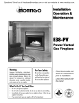
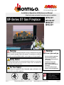
fire feature www.montigo.com Installation Operation & Maintenance Manual Check local codes and read all instructions prior to installation. BF52-ST BFL52-ST BF60-ST BF84-ST BF-Series ST Gas Fireplace BF84-ST Shown Warning: Improper installation, adjustment, alteration, service or maintenance can cause injury or property damage. Refer to this manual. For assistance or additional information consult a qualified installer, service agency or the gas supplier. Safety Notice: Glass doors on gas fireplaces are extremely hot while the fireplace is on and remain hot even after the fireplace has been turned off. Safety screens are available and can reduce the risks of severe burns. For Your Safety: Do not store or use gasoline or other flammable vapors and liquids in the vicinity of this or any other appliance. ® XG0711 C US Canadian Heating Products Inc. Langley, BC V4W 4A Warning: What to do if you smell gas • • Do not try to light any appliance. Do not touch any electrical switch; do not use any phone in your building. • Immediately call your gas supplier from a neighbor's phone. Follow the gas supplier's instructions. • If you cannot reach your gas supplier, call the fire department. • Installer: Leave this manual with the appliance. • Consumer: Leave this manual for future reference. Montigo Del Ray Corp. Ferndale, WA 98248 022410 BF-Series-ST Gas Fireplace fire feature Warning: Read this manual before installing, operating or troubleshooting this appliance. Please retain this owner's manual for future reference. Congratulations Congratulations on selecting a FireFeature Custom gas fireplace, an elagent and well designed gas fireplace built to your specifications. The Firefeature gas fireplace you have selected is designed to provide the utmost in safety, reliability, and engineering standards. As the owner of this new fireplace, you'll want to read and carefully follow all the instructions contained in this Installation, Operations and Maintenance manual. Pay special attention to all cautions, warnings, and Important warnings. This owner's manual should be retained for future reference. We suggest that you keep it with all your other important documents and product manuals. The information contained in this owner's manual, unless noted otherwise, applies to all models, and gas control systems. Your new FireFeature Custom gas fireplace will give you years of durable, reliable use. Welcome to the FireFeature family of gas fireplace products. Safety Alert Key: • DANGER! Indicates a hazardous situation which, if not avoided will result in death or serious injury. • WARNING! Indicates a hazardous situation which, if not avoided could result in death or serious injury. • CAUTION! Indicates a hazardous situation which, if not avoided, could result in minor or moderate injury. • NOTICE: Used to address practices not related to personal injury. • Important: Used to address practices not related to personal injury. Table Of Contents Congratulations Safety Alert Key Introduction................................................................................ 3 Installing the BFL52 Designer Beads............................ 14 Installation Finishing around the fireplace Installing and Framing the Fireplace............................... 4 Facing............................................................... 15 Installing the Gasline....................................................... 5 Mantels and Surrounds.................................... 15 Installation Requirements................................... 5 Operation .........................................................................16 - 17 Electrical Supply................................................. 6 Installing the Remote Switch.............................. 6 Maintenance . .......................................................................... 18 Vent Terminations............................................... 6 General......................................................................... 18 Venting................................................................ 6 Cleaning........................................................................ 18 Start-up Sequence.................................................16 - 17 Power Vent Control Box.................................................. 7 Troubleshooting............................................................. 18 Start-Up Sequence schematic........................................ 8 Warranty .................................................................................. 19 Removing & reinstall the Door........................................ 9 Appendix Installing the BF52 Logset............................................ 10 Installing the BF60 Logset..................................... 11 - 12 Notes ..................................................................................... 21 Installing the BF84 Logset.....................................13 - 14 A State of Massachusetts / Amendment...................... 20 Page 2 Part No. XG0711 - 022410 BF-Series-ST Gas Fireplace fire feature Introduction About the BF-Series-ST Power Vented Fireplaces: The BF-Series-ST See-thru Gas fireplace is available in three sizes, and is rated for Natural Gas and Propane; BF52-ST Natural Gas and Propane, at 150,000 BTU/H (43.50 Kilowatts) Input. BFL52-ST Linear Burner, Natural Gas and Propane, at 150,000 BTU/H (43.50 Kilowatts) Input. BF60-ST Natural Gas and Propane, at 200,000 BTU/H (58.00 Kilowatts) Input. BF84-ST Natural Gas and Propane, at 280,000 BTU/H (81.20 Kilowatts) Input. Warranty and Installation Information: The Montigo warranty will be voided by, and Montigo disclaims any responsibility for, the following actions: Modification of the fireplace and/or components including the vent assembly or glass doors. Use of any component part not manufactured or approved by Montigo in combination with this Montigo fireplace system. Installation other than as instructed in this manual. Consult your local Gas Inspection Branch on installation requirements for factory-built gas fireplaces. Installation & repairs should be done by a qualified contractor. Installations in Canada must conform to the current CAN/CGA B-149.1 and .2 Gas Installation Code and local regulations. This appliance must be electrically grounded in accordance with CSA C22.1 Canadian Electrical Code Part 1 and/or Local Codes. Installations in the USA must conform to local codes, or in the absense of local codes to the National Fuel Gas Code, ANSI Z223.11988. The appliance must be grounded in accordance with local codes or, in the absence of local codes, with the National Electrical Code, ANSI/NFPA 70-1987. Within the State of Massachusetts this fireplace must comply with NFPA-54 Chapter 10. Warranty and Installation Information: The Montigo warranty will be voided by, and Montigo disclaims any responsibility for, the following actions: Modification of the fireplace and/or components including vent assembly or glass doors. Use of any component part not manufactured or approved by Montigo in combination with this Montigo fireplace system. Installation other than as instructed in this manual. Consult your local Gas Inspection Branch on installation requirements for factory-built gas fireplaces. Installation & repairs should be done by a qualified contractor. CAUTION! Due to its high operating temperatures, the appliance should be located out of traffic & away from furniture and draperies. Children and adults should be alerted to the hazards of the high surface temperature, which could cause burns or clothing ignition. Young children should be carefully supervised when they are in the same room as the appliance. Clothing or other flammable materials should not be placed on or near the appliance. Part No. XG0711 - 022410 WARNING! When this appliance is installed directly on carpeting, tile or any combustible material other than wood flooring, it must be installed on a metal or wood panel extending the full width and depth of the appliance. Page 3 BF-Series-ST Gas Fireplace fire feature Installation Installing The Fireplace To install the fireplace: The BF-ST fireplace system is an engineered fireplace system, and will require you to provide the correct vent run and air supply information to the Engineering staff of Montigo. Safety, as well as efficiency of operation, must be considered when selecting the fireplace location. Try to select a location that does not interfere with room traffic, has adequate ventilation, and offers an accessible pathway for vent installation. Refer to Vent Installation Section for more information. The fireplace dimensions are shown below and on the following page: After this initial consultation with Montigo we will specify the correct power vent model for your project. The fireplace can be installed on any combustible platform, as there will be no heat transfer to the base of the fireplace “L” C/C “J” Fresh Air Supply: Connect all of the fresh air supply for this fireplace to the lower vent connections assuring no reduction or restriction to the air supply occurs, even due to unexpected circumstances. Please consider automated dampers, particularly on the intake air supply in cold climates. This is especialy important when the intake air is introduced from the top down. Cold air has the tendency to settle to the lowest point in the vent system. For extra long air supply runs, Montigo will recommend an increase in vent diameter. When changing the air supply from several incoming air connections to one vent, consult this information with your contact at Montigo. To ensure adequate operation of the vent system ensure the size of the one vent is not less than the total sum of vents that you are connecting to. Flue Gas vent run: The BF-ST fireplace system may be installed with any certified UL or ULC B-Vent. All the clearances to this B-Vent must be equivalent to the manufacture’s specifications as outlined in the installation/ operation manual. The size of this B-vent is specified in the approval process and cannot be reduced unless Montigo has re-evaluated your system. If authorized to reduce your vent size you will be issued new shop drawings reflecting the new vent connection size and specifications. The vent system may be installed vertically or horizontally, to any length, and may have numerous elbows (information of quantity as supplied to Montigo). Montigo will then re-evaluate this information and size the Power Vent to the vent restriction, and compensate for the pressure drop. Power Vent: Montigo manufactures a variety of Power vent modules as large as 5KWatts. The Power vent is commonly placed either horizontally or vertically at the end of the B-Vent run. However, we have an in-line vent module available. This Inline Power vent is for installations where an exterior module isn’t visually attractive, or permitted. Also, In-line Power vents are more complex to install, primarily due to the positive pressure in the vent system after the Power vent module. Therefore this vent run after the Power vent module must be air-tight due too the concern gas by-products may leak from the vent into the structure. All Power vent modules create a negative pressure before the module and leaks in the vent draw air from the building and will not create a safety hazard. “G” “I ” “K” “C” Window Top View “C” Opening “B” “E ” Opening “A” “H” Overall Width Front View Figure 1. Fireplace dimensions. (May not be exactly as shown) A BF52-ST 60 60 B 64 70 C 52 52 D E F G N/A 30 N/A 24 N/A 36 N/A 24 H 90 90 I 12 12 J 5 5 K 8 8 L 79 79 A BF60-ST 68 B 64 C 60 D E F G N/A 48 N/A 24 H 90 I 12 J 5 K 8 L 79 A BF84-ST 92 B C D E 108 84 N/A 60 H 92 I 14 J 5 K 8 L N/A Clearances: All building materials within the 94" by 108" area specified in Fig.2 to be non-combustible materials. The BF-Series gas fireplaces must also maintain the following clearances: BF52- ST BF60- ST BF84- ST Page 4 Sides 3" 3" 3" Back 3" 3" 3" Floor Mantle* (No door) BF-ST fireplace: The fireplace may be installed in any location that maintains proper clearances to air conditioning ducts, electrical wiring and plumbing. F G N/A 28 Mantle* (With door) 0" 0" 0" 12" 12" 12" 6" 6" 6" *Refer to Page 10. Unprotected combustible walls which are perpendicular to the fireplace opening, must not project beyond the shaded area shown in Figure 13. Part No. XG0711 - 022410 BF-Series-ST Gas Fireplace fire feature Installation Installing The Gas Line 108” The gas line must be installed before finishing the BF-ST Fireplace. Natural Gas requires a minimum inlet gas supply pressure of 5.5" W.C. & a manifold pressure of 3.5" W.C. Propane Gas requires a minimum inlet gas supply pressure of 11" W.C. & a manifold pressure of 10" W.C. Provision must also be made for a 1/8" N.P.T. plugged tapping and be accessible for test gauge connection immediately upstream of the gas supply controls to the appliance. The fireplace gas connection and the main operating gas valve is located behind the removable brick panel in the centre of the unit. It only needs to be attached to the gas line with an approved fitting, as required by the applicable installation codes. “X” “Y” “W” Gas Line access. Figure 2. Framing dimensions and clearances to combustibles. Figure 4. Gas line access. Control Cable Connection to Electrical Box The appliance and its individual shutoff valve must be disconnected from the gas supply piping system during any pressure testing of that system at test pressures in excess of 1/2 psig (3.5 kPa). The appliance must be isolated from the gas supply piping system by closing its individual manual shutoff valve during any pressure testing of the gas supply piping system at test pressures equal to or less than 1/2 psig (3.5 kPa). “X1” “X” Important: All dimensions, and design specifications are subject to approval upon quotation of fireplace and associated equipment. “Z” Figure 3. Framing dimensions side view. BF52-30 BF52-36 BF60-48 BF84 W 94 94 102 94* X 42 48 60 96* Y 64 64 72 94* Z 27 27 27 28* X1 67 73 85 * *Check with manufacturer prior to framing Part No. XG0711 - 022410 WARNING! When this appliance is installed directly on carpeting, tile or any combustible material other than wood flooring, it must be installed on a metal or wood panel extending the full width and depth of the appliance. Page 5 BF-Series-ST Gas Fireplace fire feature Installation Installation Of Electrical Supply Vent Terminations The BF-ST Fireplace is supplied with an external electrical Control Panel pre-wired by the factory. The standard gas control cable is 15 feet between the fireplace and the external panel, additional length is available upon request. The external panel is 16" x 16" x 6" and must be located in an accessible location. The C-View requires 120V electrical supply on a dedicated 15 amp fuse or circuit breaker to the Control Panel Selecting A Termination Location Installations in Canada must be electrically grounded in accordance with CSA C22.1 Canadian Electrical Code Part 1 and/or Local Codes. General Installation Requirements Installations in the USA must be electrically grounded in accordance with local codes or, in the absence of local codes, with the National Electrical Code, ANSI/NFPA 70-1987. 110V Power Supply Fuse Post Purge Control Vent Installation The BF-ST fireplace is certified for use with any approved 12" B-Vent venting components. 1" clearance to combustibles for vent pipes on all vent runs, or use the clearances specified by the B-Vent manufacturer, whichever is greater. Fan Speed Control Figure 7. Electrical Supply The electrical panel has three connection boxes on the side of the panel marked: 110 Volt Power Supply, Power Vent Motor, and Gas Control Wiring. First Connect the White, Black, and Green (Ground) wire coming from the power vent motor in the box marked Power Vent Motor. Then connect the cable from the fireplace. Last connect the power supply to the box marked 110 Volt Power Supply. See the diagram on page 7 for the cable installation. Installing The Remote Switch BF52-ST 30" Only (Without doors) This Power Vent system will depressurize the building at 1800 CFM, and a sufficient air intake system must be installed to avoid any malfuntion of other appliances that rely on room air. Power Vent Motor Gas Control Wiring Wall Switch Air Proving Switch Before installing the termination or venting, check to ensure the planned termination location is acceptable. See figure 10 & 10a below. BF52-ST and BF60-ST (With doors) This fireplace is a sealed unit and will not effect or alter the building air system. However due to the large amount of air that moves through the fireplace the net gain will be very small. BF52-ST Installation Requirements (With & Without doors) and BF60-ST Installation Requirements (With doors) Use only certified B-Vent vent components. (Use of other parts will void the Montigo warranty, and may impede the operation of the fireplace). All joints must be secured as per the instructions provided by the B-Vent manufacturer. The exhaust portion of a vent termination must not be recessed in walls or siding. Horizontal runs must be supported by a minimum of three supports per 10 feet of venting. Each Vertical Venting installation may have up to four 90° elbows. Each Horizontal Venting installation may have up to three 90° elbows. The BF-ST's two gas valves, located inside the unit and underneath the burner, may be connected to a wall switch or a hand-held remote. The valve operates on a 24V circuit. DO NOT connect the gas valve to an external circuit. The external electrical panel supplied with the fireplace is equipped with a 20 foot low voltage wire, for connecting to a wall switch of your choice, longer lengths are an option. Page 6 Part No. XG0711 - 022410 BF-Series-ST Gas Fireplace fire feature Installation Power Vent Termination Power Vent Control Box 12” Wiring requirements for Power Vent Installation 12” B-Vent Duct, One run for Horizontal or Vertical Installation Required. Power Vent Termination Figure 7b. BF-ST Standard Control Box Figure 7. Typical B-vent configurations. Exterior Power Vent / Wire Routing Installation Diagram Power Vent Termination Combustion Air Supply System Installation Requirements An intake grill will have to be installed with the same size of the total opening as the combined air supply ducts on the unit. Make sure you have calculated the restriction and selected the proper grill size. The BF-ST fireplace is supplied with two or more combustion air duct connection points. Do not reduce the size of the air supply system, or restrict the air supply in any way. On any combustion air supply run longer than 10 feet the duct should be increased in size to prevent a restriction. A vacuum safety switch, located under the burners, will monitor the combustion air supply pressure and will prevent the burner from igniting, or continuing to burn if the pressure is negative, past 0.08WC. For extremely long air supply runs the combustion air supply will have to be power assisted. One Control Cable Installation required for either Horizontal or Vertical Termination. Power Vent Termination 16”x 16”x 4” Deep Elect. Control Box 20’ Foot, 10-Conductor Cable to Fireplace, (Standard) 110 VAC 15A Supply Current From Dist. Panel To Control Box From Control Box Figure 7a. BF-ST Control Box / Power Vent Wire Routing Diagram) Part No. XG0711 - 022410 Page 7 BF-Series-ST Gas Fireplace fire feature Installation Startup Sequence: 1. Ensure that there is continuous power to the Post Purge Control Module. Supply chamber in the firebox, and it is normally closed unless inadequate combustion air supply will open the switch. 2. Ignition is initiated by turning on wall switch, which will close 6. The Post Purge Control will now power up terminal 1 and 2 with terminal 5 and 6. relay R1 activating Smart Valve No.1 as well as terminal 3 and 4 with relay R2 activating Smart Valve No.2. 3. The Post Purge Control will start the Power Vent Motor at the speed set speed on Speed Control. 7. The Smart Valve system will light the pilotand by proving the presence of a pilot flame it will fire up the burners. After the third failure 4. When adequate air flow is established the Air Proving switch will to establish a pilot the valve will lock out. close terminal 9 and 10 8. To reset the system turn the wall switch 'off' and then back 'on'. 5. Terminal 7 and 8 is the vacuum switch inside the Combustion Air 110V Power Supply 6 Amp 110V Fuse PostPurge Purge Control Post Control 110V Motor R G B B R R W To Fireplace W Bk Bk W W Bk G Bk 110V 110V 24V 24V Motor Speed Control R2 R1 G Valve 1 Page 8 Red Brn Red Red Pk Valve 2 Wall Switch Jumper Org Blu Blk / Wht Blu LVT Denotes Low Voltage Denotes Line Voltage Wall Switch Wht / Blk Legend Yel First Burner: 1,2 Black-White Second Burner: 3,4 Blue-Yellow Wall Switch: 6,7 Black-White Air Priority Switch: 9,10 Orange-Red Green is Ground Relay Blk / Yel To Wall Switch Relay LVT B Yel O R Blu / Yel P Yel Y W Bk Y Blk / Wht Bk W B Y Yel Y Wht / Blk Y Air Proving Switch Part No. XG0711 - 022410 BF-Series-ST Gas Fireplace fire feature Installation Removing and Installing the Doors (Both sides typical) Removing the doors: The BF-ST Door-Window outer trim is held in place by magnets, and the Door-window frame are held in place by fine-thread 10-24 screws. Follow the process below to remove, or install the items described. installing the doors: Install the doors in reverse order as shown in Steps 1 through 4. Important: when re-installing screws into their original location, ALWAYS hand tighten with screwdriver to ensure proper tension on all screws. Figure 14. The Fireplace as it is received from Montigo. Figure 15. (Step 2) Remove the Door-window trim by grasping the metal firmly and pull it free it from the frame. Note: Hold it as shown in Step 2 to release the hold of the magnets. Figure 14. Step 1. (Door Trim ) Figure 15. Step 2. (removal of Trim) WARNING! Do not attempt to clean glass when hot. Do not clean glass with abrasive materials as any glass etching may cause premature glass failure. Do not operate this fireplace without the glass door, or with a broken glass door. Figure 16. Step 3 (Removal of Door Frame) Figure 17. (Completed Re- moval) Figure 16. (Step 3) Remove the Door-window assembly by turning the 10-24 screws counterclockwise. Note: Have someone hold the doorwindow assembly in place until all screws are removed. Then grab the assembly from either end lifting it away from the fireplace. Place it in a safe location to store or clean. Figure 17. (Step 4) Proceed to remove glass on other side if required. Place the glass in a safe place and proceed with service or cleaning. Part No. XG0711 - 022410 Cautions: Fireplace gas control must be in the “OFF” position and pilot and main burners extinguished when cleaning appliance with a vacuum. Doors and logs can get very hot. Handle only when cool. Page 9 BF-Series-ST Gas Fireplace fire feature Installation Installing the BF52 Log Set Installing the Logs: The BF52-ST fireplace is supplied with nine ceramic fibre logs. Unpack the logs and handle them very carefully. Step 4. Place the two (2) outer Logs labeled "D". Note dimensions on both logs and flush notations. Reference, the final location for Logs "E" (Ovals, broken lines). 2” Note: Utilize the front Logrest stiles as reference. (Reference lines indicating centre line orientation, and flush end alignment). Step 1. Place the two (2) Logs Labeled "A". Note dimensions on both Logs. Rest Front and back Logs against grate tines as shown. Log D Log D 1/2” 4” Log A 6” front 2” Figure 10c. Placing Top diagonal logs D. Log A 1/2” 6” front Figure 10. Placing bottom logs A. Step 5. Completed Logset, with ember location. Note complete location of Logset and adjust if neccessary to ensure their optimum location. Sooting may occur if the Logs are not in their optimum location. Step 2. Place the one (1) Log labeled "B" . Center log "B" on the two (2) Grate tines as shown. Note the location (Ovals, broken lines) for Logs "C" Left and Right, Next Step. Log A Embers Log B Figure 10d. Placing Top diagonal logs D. front 2” Figure 10a. Placing Top diagonal log B. Step 3. Place the two (2) Logs labeled "C". Center on Ovals shown, follow dimensions and location against grate tines. (flush notations both Log "C") 6” Flush 7” Knob Log C Log C WARNING! Knob 7” Flush front 6” Figure 10b. Placing Top diagonal logs 'C'. (follow the approximate patttern to improve flame pattern, and minimize sooting). Page 10 If logs are not placed properly, excessive sooting will result. The surface of the logs will crack due to the heat from the flames. This is a normal occurance. Part No. XG0711 - 022410 BF-Series-ST Gas Fireplace fire feature Installation Installing the BF60 Log Set Step 3. Place the Log Labeled "B" in the Diagonal position as shown. Align both ends on-center with the Third Tine, (Front & Back). Installing the Logs: The BF60-ST fireplace is supplied with (9) nine ceramic fibre logs. Unpack the logs and handle them very carefully. Grate Tine 3 Note: Utilize the front & rear Logrest stiles as reference. (Reference lines indicating centre line orientation, and flush end alignment). Log B Step 1. Remove the glass door as described on Page 15. Log Tine 1 Spike 2 3 4 5 6 Grate Tine 3 7 Linear Burners Log holder Log Spike Figure. 11c Place the faux Log labelled ‘B’. (Note: Align the Log with the two (2) smooth indents facing upward, and the one (1) charred indent facing downwards toward the Linear burners). See Figure 11d & Figure 11e). (Indicated by ovals). Grate Tine 3 Log holder Tine 7 6 5 4 3 2 1 Figure. 11 BF60 Grate (Note location of the 7-Tines (front & back) and Log rests, Log spikes, etc. Log B Log B CL Step 2. Place the first Log Labeled "A" in the front center position. Extend both ends equaly, (RH & LH). Then place the Second Log “A”. Grate Tine 3 (both sides Typ.) Grate Tine 3 Figure. 11e Location Log ‘B’. Equal Log A Figure. 11f Orientation Log ‘B’. Step 4. Place the First Log Labeled "C" in the Diagonal position as shown, Figure 1g. Align one end with Grate Tine labeled No.6 and the other on the smooth indent, (indicated by oval, figure 11f & figure 11g) (Front & Back Logs Typical). Equal Figure. 11a Placing the First Log labelled ‘A’. (Note: Location of knots and location of stripped faux bark, indicated by oval at right end). (Both ‘A’ logs Typical). Log C Log B ds en ign en Al ign Log A Al ds Stripped Bark Stripped Bark Figure. 11b Placing the Second Log labelled ‘A’. (Align ends of both Logs). 1 1/2” Grate Tine 6 Figure. 11g Place Log labelled ‘C’. (Note: Dimension from Grate Tine-6, and location of smooth indent on Log ‘B’, indicated by WHITE oval at right end). See Figure 11h & Figure 11j). (Indicated by ovals). WARNING! If logs are not placed properly, excessive sooting will result. The surface of the logs will crack due to the heat from the flames. This is a normal occurance. Part No. XG0711 - 022410 Page 11 BF-Series-ST Gas Fireplace fire feature Installation Log C Log C Log D Log A Log D Log D Log B Figure. 11h Location Log ‘C’. Figure. 11j Orientation Log ‘C’. Step 5. Place the Second Log Labeled "C" in the Diagonal position as shown, Figure 11k. Align opposite to the Log Labeled "C" above, Figure 11g. Place top end flat onto the oval shown in Figure 11j above, (Log labeled 'B'). Figure. 11m measure the distance of Log's ‘D’. from the Grate tines 1. (Both Logs Typical). Step 7. Position of the two Logs Labeled "E" in their final Rest position. Place the bottom end of the Log in the Log Holder Figure 11p Below. (Both Logs labeled E Typical). Top end of the Logs Flush with Logs labeled 'A', figure 11q. Log C Log E Log Holder, (both Logs Typical). Figure. 11k Location of Second Log ‘C’. Step 6. Place the First Log Labeled "D" in the Diagonal position as shown, Figure 11m. Align the log with the flat portion down. Place the bottom end on the Log Spike as shown in Figure 11j above, (Log labeled 'B'). Figure. 11o Log Nail, (2pcs) top end of both Logs labeled ‘D’. Use a hammer to secure through Logs 'D' into Log 'B'. Figure. 11n Press lower end of both Logs labeled ‘D’. onto Log Spike, (Press firmly). Figure. 11p Place the round end of Log's ‘E’. into the Log holders. (Both Logs Typical). Log E Flush Flush 1 1/2” Grate Tine 6 Log B Flush Log A Figure. 11q Move both Logs 'E' forward or backwards to flush faces with Logs 'A', (Press firmly). spike See (Figure 11o) Log Nail Log Nail Log D Log D Log Spike Log Spike Figure. 11r Completed installation of BF60 Logset. See (Figure 11m & Figure Figure. 11L Position the Logs labelled ‘D’. (Note: Dimension from Grate Tine1, Figure 11m, and large knot at top end of the log which it rests against. See Figure 11m, Figure 11n & Figure 11o for log Setting Details). WARNING! If logs are not placed properly, excessive sooting will result. The surface of the logs will crack due to the heat from the flames. This is a normal occurance. Page 12 Part No. XG0711 - 022410 BF-Series-ST Gas Fireplace fire feature Installation Installing the BF84 Log Set Installing the Logs: The BF84-ST fireplace is supplied with (9) nine ceramic fibre logs. Unpack the logs and handle them very carefully. Step 5. Place the one (1) Log labeled "C" . Align with the grate tines as shown. Note location and direction of Log "D" oval alignment cutouts. 2 1/2” Note: Utilize the front & rear Logrest stiles as reference. (Reference lines indicating centre line orientation, and flush end alignment). 6 Log “D” Oval Cutout Step 1.Remove the glass door as described on Page 15. 8 9 7 6 5 4 3 Flush with Grate Tines Log C 2 CL Log “D” Oval Cutout 1 6 Flush with Grate Tines 2 1/2” Linear Burners 2 1 3 4 5 6 7 Figure. 12c. Place the faux Log labelled ‘C’. (Note: Align the Log with the two (2) smooth indents facing upward, and the one (1) charred indent facing downwards toward the Linear burners). See Figure 12d & Figure 12e). (Indicated by ovals). 9 8 Grate Tines Place embers in trays Spread out evenly Figure. 12 BF84 Grate (Note location of the 9-Tines (front & back) and Ember tray under Grate. Step 2. Place the embers in both trays. Spread out evenly to ensure the flame effect is symetrical. See Step 9 final Log Assembly. Step 3. Place the two (2) Log labeled "A" . Align with the grate tines as shown. Note ALL dimensions referencing grate tines are taken from the center of the Tine. (Note location of knots). Step 6. Place the two (2) curved Logs labeled "D" . Align with the grate tines, and oval alignment cutouts as shown. Note: both outer ends are flush with the grate. CL Note location of burners Log D Log A Flat 1 Knots 1 5” Figure. 12a Location of Logs 'A' and embers (Both sides Typical). Step 4. Place the two (2) Log labeled "B" . Align with the ends of 'A'. Flush Flush Log B Knot Flush with Grate Tines Note location of burners 4 Step 7. Place the two (2) straight Logs labeled "E" . Align with the grate tines, and hollows (against knot) on Logs "D" as shown. Note: both outer ends are flush with grate tines. Log A Flat 3 3 Figure. 12d Location of Logs 'D' (Log placement Typical for both). Flat Knots Flush with Grate Tines Log D CL CL CL 5” CL 4 Knot Flat Log B 9 CL Log E Flush with Grate Tines Place Log E in hollow, Log D knot Place Log E in hollow, Log D knot Log E Flush with Grate Tines CL 9 Figure. 12e Location of Logs 'E' (Log placement Typical for both). Figure. 12b Location of Logs 'B' and embers (Both sides Typical). Part No. XG0711 - 022410 Page 13 BF-Series-ST Gas Fireplace fire feature Installation Step 8. Place the two (2) straight Logs labeled "F" . Align with the corner grate tines, and dimensions shown. Note: both outer ends are flush with grate tines. 10 1/2” CL Log F Once the Trim and glass doors are removed place the marbles randomly across the pan surrounding the burners as shown in Figure 13. Log F CL 10 1/2” Flush with Grate Tines Beads The BFL52-ST is supplied with Designer Glass beads. Remove the Door and trim as shown in the previous Instruction. Follow these instructions to ensure all parts are removed or replaced as required. Flush Flush Installing the Glass Beads and Optional River Rocks 9 NOTE: DO NOT Cover burners with beads or the optional rocks, as shown in Figure 13. Note: Ensure the rocks or beads do not cover the Burners Figure. 12f Location of Logs 'F' (Log placement Typical for both). Figure 13. Installation of glass beads . Completed Assembly, Note flame pattern from burner Figure. 12g. Completed installation. Optional River Rocks The BFL52-ST has the option of installing the optional cultured rocks which mimic real stone. They are attrative yet designed to withstand a high temperature environment such as inside a gas fireplace. These may be spaced at random, or in a visual pattern of your preference. See the Montigo web site for photographs and ideas. www.montigo.com Page 14 Part No. XG0711 - 022410 BF-Series-ST Gas Fireplace fire feature Installation Fireplace Facing (Without Door, BF52-ST (30")) When selecting the finish material for your fireplace, it is important to remember the following: The face of the fireplace may be painted to match the room decor, provided you use a heat-resistant paint. Decorative facing must not extend past the fireplace opening at all, because it will interfere with the access to retainers for removal of glass door. Figure 14. Combustible mantles and facings (W/O Door). Figure 15. Combustible surrounds. Fireplace Facing (With Door, All Models) When selecting the finish material for your fireplace, it is important to remember the following: The face of the fireplace may be painted to match the room decor, provided you use a heat-resistant paint. Decorative facing must not extend past the fireplace opening at all, because it will interfere with the access to retainers for removal of glass door. Figure 14a. Combustible mantles and facings (With Door). Part No. XG0711 - 022410 Page 15 BF-Series-ST Gas Fireplace fire feature Operation - Model BF-ST with Honeywell Electronic Ignition For Your Safety - READ BEFORE LIGHTING: WARNING: If you do not follow these instructions exactly, a fire or explosion may result causing property damage, personal injury or loss of life. A. This appliance is equipped with an ignition system that lights the pilot burner automatically. Do not attempt to light the pilot by hand. B. BEFORE LIGHTING smell all around the appliance area for gas. Be sure to smell next to the floor because some gas is heavier than air and will settle on the floor. What To Do If You Smell Gas: ■ Do not try to light any appliance. ■ Do not touch any electrical switch; do not use any phone in your building. ■ Immediately call your gas supplier from a neighbour's phone. Follow the gas supplier's instructions. ■ If you cannot reach your gas supplier, call the Fire Department. C. Use only your hand to push in or turn the gas control knob. Never use tools. If the knob will not push in or turn by hand, don't try to repair it, call a qualified service technician. Force or attempt to repair may result in a fire or explosion. D. Do not use this appliance if any part has been under water. Immediately call a qualified service technician to inspect the appliance and to replace any part of the control system, and any gas control which has been under water. Lighting Instructions: 1. STOP! Read the safety information above on this label. 2. Remove the lower Horizontal access panel. 8. If the fireplace does not operate, follow the instructions "To Turn Off Gas To Appliance" and call your service technician or gas supplier. 3. Turn switch on the gas control to OFF". 4. Wait 5 minutes to clear out any gas. If you smell gas, STOP! Follow "B" in the safety information above on this label. If you don't smell gas, go to the next step. 5. Turn switch on the gas control to "ON". NOTE: This unit is equipped with an ignition system that lights the pilot burner automatically. Do not attempt to light the pilot by hand. 6. Turn on wall switch. 7. Replace the lower Horizontal access panel. Gas Inlet Gas Control Switch Shown in "On" Position To Turn Off Gas To Appliance: 1. Turn off remote switch. 3. Turn the switch on the gas control to "Off". 2. Remove the lower Horizontal access panel.. 4. Replace the lower Horizontal access panel. Page 16 Part No. XG0711 - 022410 BF-Series-ST Gas Fireplace fire feature Operation - Model BF-ST-A with American Flame Electronic Ignition For Your Safety - READ BEFORE LIGHTING: WARNING: If you do not follow these instructions exactly, a fire or explosion may result causing property damage, personal injury or loss of life. A. This appliance is equipped with an ignition system that allows for both continuous pilot operation as well as an electronic ignition that lights the pilot burner automatically. Do not attempt to light the pilot by hand. What To Do If You Smell Gas: ■ Do not try to light any appliance. Do not touch any electrical switch; do not use any phone ■ in your building. Immediately call your gas supplier from a neighbour's ■ phone. Follow the gas supplier's instructions. ■ If you cannot reach your gas supplier, call the Fire Department. B. BEFORE LIGHTING smell all around the appliance area for gas. Be sure to smell next to the floor because some gas is heavier than air and will settle on the floor. Lighting Instructions: I na l S ADJ. io POWER Red Red Black Black Black Brown Brown To Turn Off Gas To Appliance: Green 1. Turn off remote switch. 2. Remove the lower Horizontal access panel.. Part No. XG0711 - 022410 IPI 6VAC 200mA AC ADAPTOR Wall Switch (SWI) Manual Hi/Lo Control Module Learn pt Orange (Igniter) AUX O 8. If the fireplace does not operate, follow the instructions "To Turn Off Gas To Appliance" and call your service technician or gas supplier. 9. If you wish to operate the Fireplace without the Continous Pilot simply turn the switch on the control module to "Continuous Pilot Off" and follow instructions White 6-8.(Sensor) Continuous Pilot Remote/Off Off/On 1. STOP! Read the safety information above on this label. 2. Remove the lower Horizontal access panel.. 3. If the switch on the control module is set to "Continuous Pilot Pilot Assembly Off" then the pilot will light when the appliance is turned on by the remote switch. When switched to "Continuous Pilot On" then the control module will attempt to light the pilot until it detects that the pilot has been successfully lit. 4. With the control module set to "Continuous Pilot Off" wait 5 minutes to clear out any gas. If you smell gas, STOP! Follow "B" in the safety information above on this label. If you don't smell gas, go to the next step. Emergency Battery Power (4 x AA) 5. Turn switch on the control module to "Continuous Pilot On" This will initiate the lighting of the pilot. NOTE: This unit is equipped with an ignition system that lights the pilot burner automatically. Do not attempt to light the pilot by hand. 6. Turn on wall switch. 7. Replace the lower Horizontal access panel. White White Orange 3. Turn the switch on the Control Module to "Continuous Pilot Off". Main Pilot 4. Replace the lower Horizontal access panel. Main Gas Output Main Gas Input Page 17 BF-Series-ST Gas Fireplace fire feature Maintenance Gas Control Valve WARNING! Do not attempt to clean glass when hot. Bk L42DF-ST W Do not clean glass with abrasive materials as any glass etching may cause premature glass failure. R Connector GasC ontrol Do not operate this fireplace without the glass door, or with a broken glass door. General Control (SV9501M) Honeywell Gas Have the fireplace installation inspected yearly, including a visual check of the vent system, the burner and the pilot flame. For your convenience a 1/8" manifold pressure tap is supplied on the gas valve for a test gauge connection. See Figure 17. For Natural Gas this appliance requires a minimum inlet pressure of 5.5" W.C. and a manifold pressure of 3.5" W.C. For Propane Gas this appliance requires a minimum inlet pressure of 11" W.C. and a manifold pressure of 10" W.C. Always keep the fireplace area clear and free of combustible materials, as well as gasoline and other flammable vapours and liquids. Do not use this appliance if any part has been under water. Immediately call a qualified service technician to inspect the appliance and to replace any part of the control system and any gas control which has been under water. Cleaning When the fireplace is first activated, there may be some smoking and a visible film may be left on the glass. This is a normal condition, and is the result of burning of protective coatings on new metal. Glass must be cleaned periodically to remove any film (which is a normal biproduct of combustion) which may be visible. Film can easily be removed by removing the door, as shown on page 8. Handle the door carefully, and clean it with non-abrasive glass cleaners. One of the most effective products is Kel Kem. Harness Connector Pilot Electrical Pilot Assembly Honeywell (Q3450) Figure 16. Honeywell SV9501 gas valve. Troubleshooting HONEYWELL SV9500 /9600 Troublshooting Sequence NOTE: Before Troubleshooting, Familiarize Yourself With START The Startup And Checkout Procedure. SV9500 / SV9600 is powered (24VAC nominal) NO Use a vacuum cleaner or whisk broom to keep the control compartment, burner, and firebox free from dust and lint. Turn gas on. Pilot Burner Lights? If your fireplace still does not operate correctly, consult your dealer or the manufacturer. All service and repairs should be performed by a qualified agency. All spare parts, optional fans, and optional trim finishes are available from your local dealer or the manufacturer. Page 18 YES NO YES SYSTEM OK Unplug Pilot Burner Cable, Measure Voltage at SV9500/SV9600 HSI Terminals (24VAC Nominal, see INSET) NO Replace SV9500/ SV9600 Replace Igniter / Flame Rod Assembly Replace SV9500/SV9600 NO Measure Volume to SV9500 / SV9600 Voltage must be at least 19.5 VAC NO YES YES Main Valve opens? HSI - Line voltage power Terminals - Low voltage transformer - Limit Controller - Thermostat - Wiring - Air proving switch on combustion air blower system -Vent damper (if used) is open and end switch made YES Igniter warms up and glows red. Pilot Valve opens. Logs may be cleaned periodically with a vacuum to remove soot or other contaminates. NO YES Silicone seals on inner door during initial firing will "off gas", leaving a visual deposit of a white substance on combustion chamber walls. This can easily be removed using normal household products. INSET CHECK: - Turn Gas Supply Off - Set thermostat to call for heat Check Transformer Line Volt Supply Replace Igniter / Flame Rod Assembly NO Replace Igniter / Flame Rod Assembly and retain. Restart troubleshooting Sequence. Does main valve open? YES NO Replace SV9500 / SV9600. Save old Igniter/ Flame Rod Assembly for service. Discard old Igniter / Flame Rod Assembly Part No. XG0711 - 022410 BF-Series-ST Gas Fireplace fire feature Warranty The Warranty The Companies warrants the Montigo Gas Appliance to be free from defects in materials and workmanship at the time of manufacture. On the Montigo, there is a ten-year warranty on the firebox and its components, a five-year warranty on the main burner, and a one-year warranty on the pilot burner, gas control valve and fibre logs. Glass, plated/painted finishes, and refractory lining are exempt. Remedy And Exclusions The coverage of this Warranty is limited to all components of the Gas Appliance manufactured by The Companies. This Warranty only covers Montigo Gas Appliances installed in the United States or Canada. If the components of the Gas Appliance covered by this Warranty are found to be defective within the time frame stated (see The Companies right of investigation outlined below). The Companies will, at its option, replace or repair defective components of the Gas Appliance manufactured by The Companies at no charge, and will also pay for reasonable labour costs incurred in replacing or repairing components. If repair or replacement is not commercially practical, The Companies will, at its option, refund the purchase price of the Montigo Gas Appliance. This Warranty covers only parts and labour as provided above. In no case shall The Companies be responsible for materials, components, or construction which are not manufactured or supplied by The Companies, or for the labour necessary to install, repair or remove such materials, components or construction. All replacement or repair components will be shipped F.O.B. the nearest The Companies factory. Qualifications To The Warranty The Gas Appliance Warranty outlined above is further subject to the following qualifications: (1) The Gas Appliance must be installed in accordance with The Companies installation instructions and local building codes. The Warranty on this Montigo Gas Appliance covers only the component parts manufactured by The Companies. The use of components manufactured by others with this Montigo Gas Appliance could create serious safety hazards, may result in the denial of certification by recognized national safety agencies, and could be in violation of local building codes. This warranty does not cover any damages occurring from the use of any components not manufactured or supplied by The Companies (2) The Montigo Gas Appliance must be subjected to normal use. The Gas Appliances are designed to burn gas only. Burning conventional fireplace fuels such as wood, coal or any other solid fuel will cause damage to the Gas Appliance, will produce excessive temperatures and will result in a fire hazard. Limitations On Liability It is expressly agreed and understood that The Companies sole obligation, and purchaser's exclusive remedy under this Warranty, under any other warranty, expressed or implied, or in contract, tort or otherwise, shall be limited to replacement, repair, or refund, as specified above. In no event shall The Companies be responsible for any incidental or consequential damages caused by defects in its products, whether such damage occurs or is discovered before or after replacement or repair, and whether or not such damage is caused by The Companies negligence. Some states do not allow the exclusion or limitation of incidental or consequential damages, so the above limitation or exclusion may not apply to you. The duration of any implied warranty with respect to this Montigo Gas Appliance is limited to the duration of the foregoing warranty. Some states do not allow limitation on how long an implied warranty lasts, so the above may not apply to you. Investigation Of Claims Against Warranty The Companies reserves the right to investigate any and all claims against this Warranty and to decide upon method of settlement. The Companies Are Not Responsible For Work Done Without Written Consent The Companies shall in no event be responsible for any warranty work done without first obtaining The Companies written consent. Dealers Have No Authority To Alter This Warranty The Companies employees and dealers have no authority to make any warranties nor to authorize any remedies in addition to or inconsistent with those stated above. How To Register A Claim Against Warranty In order for any claim under this Warranty to be valid, The Companies must be notified of the claimed defect in writing or by telephone, as soon as reasonably possible after the defect is discovered. Claims against this Warranty in writing should include the date of installation, and a description of the defect. Other Rights Canadian Heating Products Inc. and/or Montigo DelRay Corp. reserves the right to make changes at any time, without notice, in design, materials, specifications, prices and also to discontinue colors, styles and products. Part No. XG0711 - 022410 Page 19 BF-Series-ST Gas Fireplace fire feature Appendix B - State of Massachusetts Amendment (Gas Fireplace / Equipment sold in the State of Massachusetts) 5.08: Modifications to NFPA-54, Chapter 10 (1) Revise NFPA-54 section 10.5.4.2 by adding a second exception as follows: Existing chimneys shall be permitted to have their use continued when a gas conversion burner is installed, and shall be equipped with a manually reset device that will automatically shut off the gas to the burner in the event of a sustained back-draft. (2) Revise 10.8.3 by adding the following additional requirements: (a) For all side wall horizontally vented gas fueled equipment installed in every dwelling, building or structure used in whole or in part for residential purposes, including those owned or operated by the Commonwealth and where the side wall exhaust vent termination is less than seven (7) feet above finished grade in the area of the venting, including but not limited to decks and porches, the following requirements shall be satisfied: 1. INSTALLATION OF CARBON MONOXIDE DETECTORS. At the time of installation of the side wall horizontal vented gas fueled equipment, the installing plumber or gas fitter shall observe that a hard wired carbon monoxide detector with an alarm and battery back-up is installed on the floor level where the gas equipment is to be installed. In addition, the installing plumber or gas fitter shall observe that a battery operated or hard wired carbon monoxide detector with an alarm is installed on each additional level of the dwelling, building or structure served by the side wall horizontal vented gas fueled equipment. It shall be the responsibility of the property owner to secure the services of qualified licensed professionals for the installation of hard wired carbon monoxide detectors a. In the event that the side wall horizontally vented gas fueled equipment is installed in a crawl space or an attic, the hard wired carbon monoxide detector with alarm and battery back-up may be installed on the next adjacent floor level. b. In the event that the requirements of this subdivision can not be met at the time of completion of installation, the owner shall have a period of thirty (30) days to comply with the above requirements; provided, however, that during said thirty (30) day period, a battery operated carbon monoxide detector with an alarm shall be installed. 2. APPROVED CARBON MONOXIDE DETECTORS. Each carbon monoxide detector as required in accordance with the above provisions shall comply with NFPA 720 and be ANSI/UL 2034 listed and IAS certified. 3. SIGNAGE. A metal or plastic identification plate shall be permanently mounted to the exterior of the building at a minimum height of eight (8) feet above grade directly in line with the exhaust vent terminal for the horizontally vented gas fueled heating appliance or equipment. The sign shall read, in print size no less than one-half (1/2) inch in size, “GAS VENT DIRECTLY BELOW. KEEP CLEAR OF ALL OBSTRUCTIONS”. 4. INSPECTION. The state or local gas inspector of the side wall horizontally vented gas fueled equipment shall not approve the installation unless, upon inspection, the inspector observes carbon monoxide detectors and signage installed in accordance with the provisions of 248 CMR 5.08(2)(a)1 through 4. (b) EXEMPTIONS: The following equipment is exempt from 248 CMR 5.08(2)(a)1 through 4: 1. The equipment listed in Chapter 10 entitled “Equipment Not Required To Be Vented” in the most current edition of NFPA 54 as adopted by the Board; and 2. Product Approved side wall horizontally vented gas fueled equipment installed in a room or structure separate from the dwelling, building or structure used in whole or in part for residential purposes. (c) MANUFACTURER REQUIREMENTS - GAS EQUIPMENT VENTING SYSTEM PROVIDED. When the manufacturer of Product Approved side wall horizontally vented gas equipment provides a venting system design or venting system components with the equipment, the instructions provided by the manufacturer for installation of the equipment and the venting system shall include: 1. Detailed instructions for the installation of the venting system design or the venting system components; and 2. A complete parts list for the venting system design or venting system. (d) MANUFACTURER REQUIREMENTS - GAS EQUIPMENT VENTING SYSTEM NOT PROVIDED. When the manufacturer of a Product Approved side wall horizontally vented gas fueled equipment does not provide the parts for venting the flue gases, but identifies “special venting systems”, the following requirements shall be satisfied by the manufacturer: 1. The referenced “special venting system” instructions shall be included with the appliance or equipment installation instructions; and 2. The “special venting systems” shall be Product Approved by the Board, and the instructions for that system shall include a parts list and detailed installation instructions. (e) A copy of all installation instructions for all Product Approved side wall horizontally vented gas fueled equipment, all venting instructions, all parts lists for venting instructions, and/or all venting design instructions shall remain with the appliance or equipment at the completion of the installation. (3) After NFPA-54 section 10.10.4.2 add a new section 10.10.4.3 as follows: When more than four gas appliances are to be vented through a common gas vent or common horizontal vent manifold, a plan of the proposed vent installation shall be submitted to the Inspector and the serving gas supplier for review and approval. Extraction from: Massachusets Rules and Regulations 5.00: Amendments To 2002 Edition Of ANSI Z223.1-NFPA-54 Page 20 Part No. XG0711 - 022410 BF-Series-ST Gas Fireplace fire feature Notes Part No. XG0711 - 022410 Page 21 fire feature XG0711 - 022410 Canadian Heating Products Inc. Langley, BC V4W 4A1 Montigo Del Ray Corp. Ferndale, WA 98248