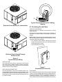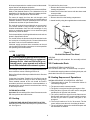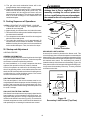
1
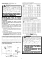
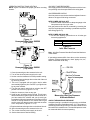
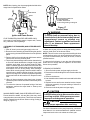
®
H eating
¡
A ir C onditioning
A higher standard of com fort
PGA**C, PGB**C and
PGD**C Single Package
Gas-Electric Heating
and Cooling Unit
Installation Instructions
Affix this manual, Specification Sheet and User Information manual adjacent to the unit.
Contents
ATTENTION INSTALLING PERSONNEL ............. 1
I. Safety Information ............................................ 2
II. General Information ......................................... 3
III. Rigging and Handling .................................... 3
IV. Gas Piping ....................................................... 4
V. Electrical Wiring ............................................... 7
Vl. Circulating Air and Filters .............................. 8
VII. Venting ........................................................... 9
VIII. Condensate Drain ......................................... 9
IX. Heating Sequence of Operations .................. 9
X. Cooling Sequence of Operations ................. 10
Xl. Startup and Adjustment ............................... 10
XII. Maintenance ................................................ 13
XIII. Accessories and Functional Parts ............ 15
Amana Forced Air Central Units Design Complies With Requirements Embodied in The American National Standard / National Standard of Canada Shown
Below.
ANSI Z21.47•CAN/CGA-2.3 Central Furnaces
RECOGNIZE THIS SYMBOL AS A SAFETY PRECAUTION
ATTENTION INSTALLING PERSONNEL
As a professional installer you have an obligation to
know the product better than the customer. This includes all safety precautions and related items.
Prior to actual installation, thoroughly familiarize yourself with this Instruction Manual. Pay special attention
to all safety warnings. Often during installation or repair
it is possible to place yourself in a position which is
more hazardous than when the unit is in operation.
product safely and to know it well enough to be able to
instruct a customer in its safe use.
Safety is a matter of common sense...a matter of
thinking before acting. Most dealers have a list of
specific good safety practices...follow them.
The precautions listed in this Installation Manual should
not supersede existing practices but should be considered as supplemental information.
Remember, it is your responsibility to install the
January1998(1)
Amana
Fayetteville, TN 37334
10692406
WARNING
I. Safety Information
To prevent death, personal injury, or
property damage due to improper
installation, adjustments, alterations,
service or maintenance, when servicing or
performing maintenance to this unit consult
this manual, service manual, qualified
installer, service agency or gas supplier.
IMPORTANT
TO THE INSTALLER
Before installing this unit please read this manual and the
Specification Sheet to familiarize yourself on the specific
items which must be adhered to such as maximum external
static pressure to unit, air temperature rise, minimum or
maximum CFM and motor speed connections.
WARNING
TO THE OWNER
It is important to complete the owner registration card and
mail it immediately. This will assist Amana in contacting you
if any service or warranty information should change in the
future. When completing the registration card, be sure to
include the Model, Manufacturing and Serial Numbers, plus
the installation date.
This product contains or produces a
chemical(s) which may cause death or
serious illness and which are known by the
State of California to cause cancer, birth
defects or other reproductive harm.
The warranty certificate is also supplied with the unit. Read
the warranty carefully and note what is covered. Keep the
warranty certificate in a safe place so you can find it if
necessary.
IMPORTANT NOTE: This unit must not be used as a
“construction heater” during the finishing phases of
construction on a new structure. This type of use may
result in premature failure of the unit due to extremely
low return air temperatures and exposure to very dirty
atmospheres.
If additional operating instructions are required, call the
dealer where the purchase was made. Keep this literature in
a safe place for future reference.
LOCATING THE UNIT
WARNING
WARNING
To prevent death, personal injury or property
damage due to fire or explosion, installation
procedures in this manual must be followed
exactly.
To prevent death, personal injury, property
damage or equipment damage, the
following points must be observed when
installing the unit.
WARNING
ALL INSTALLATIONS:
• For proper flame pattern within the heat exchanger and
proper condensate drainage, the unit must be mounted
level.
• The flue outlet hood must be at least 12 inches from any
opening through which flue gases could enter a building,
and at least three feet above any forced air inlet located
within ten feet. The economizer/manual fresh air intake/
motorized fresh air intake and combustion air inlet
mounted on the unit are not affected by this restriction.
• To avoid possible corrosion of the heat exchanger, do
not locate the unit in an area where the outdoor air (i.e.
combustion air for the unit) will be frequently contaminated by compounds containing chlorine or fluorine.
Common sources of such compounds include swimming pools and chlorine bleaches, paint stripper, adhesives, paints, varnishes, sealers, waxes (which are not
yet dried) and solvents used during construction and
remodeling. Various commercial and industrial processes may also be sources of chlorine/fluorine compounds.
• To avoid possible illness or death of the building occupants, do NOT locate outside air intake device (economizer, manual fresh air intake, motorized fresh air
intake) too close to an exhaust outlet, gas vent termination, or plumbing vent outlet. For specific distances
required, consult local codes.
Should overheating occur or the gas supply
fail to shut off, turn off the manual gas
control valve to the unit before shutting off
the electrical supply.
WARNING
To prevent death, personal injury or property
damage, do not use this unit if any part of
the unit has been under water. Immediately
call a qualified service technician to inspect
the unit and to replace any part of the
control system and any gas control which
has been under water.
If you smell gas:
• Do not try to light appliance.
• Do not touch any electrical switch: do not use any
phone in building.
• Immediately call gas supplier from a neighbor’s
phone. Follow gas supplier’s instructions.
• If gas supplier cannot be reached, call fire department.
2
• Allow clearances from the enclosure as shown in Speci- of the area to be conditioned. The loads should be calcufication Sheet for fire protection, proper operation, and
service access. These clearances must be permanently maintained.
The combustion air inlet and flue outlet hoods on the
side of the unit must never be obstructed. If used, do not
allow the economizer/manual fresh air damper/ motorized fresh air damper to become blocked by snow or
debris. In some climates or locations, it may be necessary to elevate the unit to avoid these problems.
When the unit is heating, the temperature of the return
air entering the unit must be between 50° F and 100° F.
Provisions must be made for adequate combustion and
ventilation air in accordance with Section 5.3, Air for
Combustion and Ventilation, of the National Fuel Gas
Code, ANSI Z223.1, or Sections 7.2, 7.3 or 7.4 of CAN/
CGA B149 Installation Codes, or applicable provisions
of the local building codes.
lated by an approved method or in accordance with
A.S.H.R.A.E. Guide or Manual J - Load Calculations published by the Air Conditioning Contractors of America.
GROUND LEVEL INSTALLATIONS ONLY:
• When the unit is installed on the ground adjacent to the
building, a level concrete (or equal) base is recommended. Prepare a base the same physical size as the
unit or slightly larger and 3 inches thick.
• The base should also be located where no runoff of
water from higher ground can collect in the unit.
1. Make notation on delivery receipt of any visible damage
to shipment or container.
2. Notify carrier promptly and request an inspection.
3. In case of concealed damage, carrier should be notified
as soon as possible-preferably within 5 days.
4. File the claim with the following supporting documents
within the 9 month statute of limitations.
a. Original Bill of Lading, certified copy, or indemnity
bond.
b. Original paid freight bill or indemnity in lieu thereof.
c. Original invoice or certified copy thereof, showing
trade and other discounts or reductions.
d. Copy of the inspection report issued by carrier representative at the time damage is reported to the carrier.
The carrier is responsible for making prompt inspection of damage and for a thorough investigation of
each claim. The distributor or manufacturer will not
accept claims from dealers for transportation damage.
•
•
•
Obtain from:
American National Standards Institute
1430 Broadway
New York, NY 10018
TRANSPORTATION DAMAGE
All units are securely packed in shipping containers approved by the International Safe Transit Association. The
carton should be checked upon arrival for external damage.
If damage is found, a request for inspection by carrier agent
should be made in writing immediately.
The unit should be carefully inspected upon arrival for
damage and bolts or screws which may have loosened in
transit. In the event of damage, the consignee should:
ROOFTOP INSTALLATIONS ONLY:
• To avoid possible personal injury or property damage,
the roof must have sufficient structural strength to carry
the weight of the unit(s) and snow or water loads as
required by local codes.
• The unit may be installed directly on wood floors or on
Class A, Class B, or Class C roof covering material.
• To avoid possible personal injury, a safe, flat surface for
service personnel should be provided.
NOTE: Refer to Specification Sheet shipped with the
unit or the unit Rating Plate for approved duct orientation, before using down discharge openings.
NOTE: When inspecting the unit for transportation damage,
remove all packaging materials. Recycle or dispose the
packaging material according to local codes.
II. General Information
WARNING
III. Rigging and Handling
To prevent death, personal injury or property
damage due to fire, explosions, smoke,
soot, condensation, electric shock or
carbon monoxide, this unit must be properly
installed, repaired, operated and
maintained.
CAUTION
To prevent property damage, the unit should
remain in an upright position during all
rigging and moving operations. To facilitate
lifting and moving when a crane is used,
place the unit in an adequate cable sling.
This unit is approved only for an outdoor installation.
To assure that your unit operates safely and efficiently, it
must be installed, operated, and maintained in accordance
with these installation and operating instructions, all local
building codes and ordinances, or in their absence, with the
latest edition of the National Fuel Gas Code. (ANSI Z223.1)
and National Standard of Canada (CAN/CGA-2.3).
NOTE: Refer to Specification Sheet shipped with the unit or
the unit Rating Plate for approved duct orientation, before
using down discharge openings.
Important: If using bottom discharge with roof curb, ductwork should be attached to the curb prior to installing the
unit. Ductwork dimensions are shown in roof curb installation instructions.
The heating and cooling capacities of the unit should be
greater than or equal to the design heating and cooling loads
3
Refer to the Roof Curb Installation Instructions for proper
curb installation. Curbing must be installed in compliance
with the National Roofing Contractors Association Manual.
The minimum supply pressure should not vary from that
shown in the table above because this could prevent the unit
from having dependable ignition. In addition, gas input to the
burners must not exceed the rated input shown on the rating
plate. Overfiring of the unit could result in premature heat
exchanger failure.
Lower unit carefully onto roof mounting curb. While rigging
unit, center of gravity will cause condenser end to be lower
than supply air end.
If using a fork lift, see Figure 1 for location of fork prongs.
Make certain prongs support unit weight.
HIGH ALTITUDE DERATE (US. INSTALLATIONS
ONLY)
IMPORTANT NOTE: The gas/electric units will naturally
derate itself with altitude. Do not attempt to increase the
firing rate by changing orifices or increasing the manifold
pressure. This can cause poor combustion and equipment
failure.
Fork Lift From
Back Of Unit
At all altitudes, the manifold pressure must be within 0.3
inches W.C. of that listed on the “Specification Sheet” for the
fuel used. At all altitudes and with either fuel, the air temperature rise must be within the range listed on the unit nameplate.
Refer to the “Specification Sheet” for kits for conversion
from natural gas to propane gas and for altitude adjustments.
PIPING
IMPORTANT NOTE: To avoid possible unsatisfactory operation or equipment damage due to under firing of equipment, do not undersize the natural/propane gas piping from
the meter/tank to the unit. When sizing a trunk line as shown
in Table 2, include all appliances on that line that could be
operated simultaneously.
Figure 1
Rigging
The rating plate is stamped with the model number, type of
gas and gas input rating. Make sure the unit is equipped to
operate on the type of gas available.
IV. Gas Piping
IMPORTANT NOTE: This unit is factory set to operate on
natural gas at the altitudes shown on the rating plate.
The gas line installation must comply with local codes, or in
the absence of local codes, with the latest edition of the
National Fuel Gas Code (ANSI Z223.1).
WARNING
To prevent death, personal injury or property
damage when either using propane gas
alone or at higher altitudes, obtain and
install the proper conversion kit(s). Failure
to do so can result in unsatisfactory
operation and/or equipment damage. High
altitude kits are for U.S. installations only
and are not approved for use in Canada.
NATURAL GAS CONNECTION
Natural Gas Capacity of Pipe
in Cubic Feet of Gas Per Hour (CFH)
Nominal Black Pipe Size (inches)
Length of
Pipe in Feet
1/2
3/4
1
1 1/4
1 1/2
10
132
278
520
1050
1600
20
92
190
350
730
1100
30
73
152
285
590
980
40
63
130
245
500
760
50
56
115
215
440
670
60
50
105
195
400
610
70
46
96
180
370
560
80
43
90
170
350
530
90
40
84
160
320
490
100
38
79
150
305
460
Pressure = .50 PSIG or less and Pressure Drop of 0.3" W.C. (Based
on 0.60 Specific Gravity Gas)
The rating plate is stamped with the model number, type of
gas and gas input rating. Make sure the unit is equipped to
operate on the type of gas available.
Inlet Gas Pressure
Natural
Propane
Min. 5.0" W.C., Max. 10.0" W.C.
Min. 11.0" W.C., Max. 13.0" W.C.
Inlet Gas Pressure Must Not Exceed the Maximum Value Shown in
Table Above.
CFH = BTUH Furnace Input
Heating Value of Gas (BTU/Cubic Foot)
Table 1
Table 2
4
Refer to Figure 2 for the general layout at the unit. The
CHECKING THE GAS PIPING
following rules apply:
CAUTION
1. Use black iron or steel pipe and fittings for the building
piping.
2. Use pipe joint compound on male threads only. Pipe
joint compound must be resistant to the action of the fuel
used.
3. Use ground joint unions.
4. Install a drip leg to trap dirt and moisture before it can
enter the gas valve. The drip leg must be a minimum of
three inches long.
5. Use two pipe wrenches when making connection to the
gas valve to keep it from turning.
6. Install a manual shut-off valve in a convenient location
(within six feet of unit) between the meter and the unit.
To prevent personal injury or property
damage due to fire, the following
instructions must be performed regarding
gas connections and pressure testing:
• The unit and its gas connections must be
leak tested before placing in operation.
Because of the danger of explosion or
fire, never use a match or open flame to
test for leaks. Never exceed specified pressures for testing. Higher pressure may
damage gas valve and cause overfiring
which may result in premature heat exchange failure.
7. Tighten all joints securely.
8. The unit must be connected to the building piping by one
of the following methods:
• Rigid metallic pipe and fittings
• Semirigid metallic tubing and metallic fittings (Aluminum alloy tubing must not be used in exterior locations)
• Listed gas appliance connectors used in accordance
with the terms of their listing that are completely in the
same room as the equipment
• In the prior two methods above the connector or
tubing must be protected from physical and thermal
damage. Aluminum alloy tubing and connectors must
be coated to protect against external corrosion when
in contact with masonry, plaster or insulation or are
subject to repeated wettings by liquids (water - not rain
water, detergents or sewage)
• This unit and its shut-off valve must be
disconnected from the gas supply during
any pressure testing of that system at test
pressures in excess of 1/2 PSIG (3.48
kPa).
• This unit must be isolated from the gas
supply system by closing its manual shutoff valve during any pressure testing of
the gas supply piping system at test pressures equal to or less than 1/2 PSIG
(3.48kPa).
WARNING
Manual
Shut-Off
Valve
To avoid personal injury or property
damage, be sure there is no open flame in
the vicinity during air bleeding procedure.
Gas
Valve
There will be air in the gas supply line after testing for leaks
on a new installation. Therefore, the air must be bled from
the line by loosening the ground joint union until pure gas is
expelled. Tighten union and wait for five minutes until all gas
has been dissipated in the air. Be certain there is no open
flame in the vicinity during air bleeding procedure. The unit
is placed in operation by closing the main electrical disconnect switch for the unit.
Drip Leg
Ground Joint Union
(Installed Ahead Of Gas Valve)
Reduce coupling 1/2" x 1/8",
with 1/8" pipe plug to measure
line gas pressure.
Figure 2
Proper Piping Practice
5
TANKS AND PIPING FOR PROPANE GAS
INSTALLATIONS
WARNING
To prevent death, personal injury or property
damage due to fire or explosion caused by
a propane gas leak, install a gas detecting
warning device. Since rust can reduce the
level of odorant in propane gas, a gas
detecting warning device is the only reliable
way to detect a propane gas leak. Contact a
local propane gas supplier about installing
a gas detecting warning device.
IMPORTANT NOTE: Propane gas conversion
kits must be installed to convert units to propane
gas. See Specification Sheet for kit part number
for this model.
All propane gas equipment must conform to the safety
standards of the National Board of Fire Underwriters (See
NBFU Manual 58).
For satisfactory operation, propane gas supply pressure
must be 10 inch W.C. at the unit manifold with all gas
appliances in operation. Maintaining proper gas pressure
depends on three main factors:
1. Vaporization rate, which depends on (a) temperature of
the liquid, and (b) wetted surface area of the container
or containers.
2. Proper pressure regulation.
3. Pressure drop in lines between regulators, and between
second stage regulator and the appliance. Pipe size
required will depend on length of pipe run and total load
of all appliances.
Table 3
Propane Gas Pipe Sizing
Complete information regarding tank sizing for vaporization,
recommended regulator settings and pipe sizing is available
from most regulator manufacturers and propane gas suppliers.
WARNING
To prevent death, serious personal injury
or property damage due to fire or explosion
caused by a propane gas leak, install a gas
detecting warning device.
If the propane gas unit is installed in an
excavated area or a confined space, a
warning device is required due to:
• Propane gas is heavier than air and any
leaking gas can settle in any low areas
or confined spaces.
• Propane gas odorant may fade, making
the gas undetectable except with a
warning device.
If the presence of gas is suspected, follow
the instructions on Page 2 of this manual.
Since propane gas will quickly dissolve white lead or most
standard commercial compounds, special pipe dope must
be used. Shellac base compounds resistant to the actions of
liquefied petroleum gases such as Gasolac, Stalactic, Clyde’s
or John Crane are satisfactory.
Please refer to Figure 3 for typical propane gas installations.
Figure 3
Typical Propane Gas Piping
6
Refer to the unit wiring diagram for electrical connections.
When installed, the unit must be electrically grounded in
accordance with local codes or in the absence of local
codes, with the National Electrical Code, ANSI/NFPA No.
70, and/or the CSA C22.1 Electrical Code, if an external
source is utilized.
V. Electrical Wiring
LOCATING THE THERMOSTAT
Thermostat should be mounted 5 feet above the floor, on a
vibration free inside wall in a room or a hallway that has good
air circulation.
Movement of air should not be obstructed by furniture, door,
draperies, etc. The thermostat should not be mounted where
it will be affected by drafts, hot or cold water pipes or air ducts
in walls, radiant heat from fireplace, lamps, the sun, television, etc. Consult the Instruction Sheet packaged with
thermostat for mounting instructions.
WARNING
To avoid death or personal injury due to
electrical shock, wiring to the unit must be
properly grounded.
CAUTION
All units have one stage of heating and one stage of mechanical cooling. Units which will have economizers may use
thermostats with one or two stages of cooling.
To avoid personal injury or property damage
due to fire, use only copper conductors.
WARNING
CAUTION
To avoid death or personal injury due to
electrical shock, disconnect the electrical
power before electrically connecting the
unit.
To prevent improper and dangerous
operation due to wiring errors, label all
wires prior to disconnection when servicing
controls. Verify proper operation after
servicing.
The units are designed for operation on 60 hertz current and
at voltages as shown on the rating plate. All internal wiring in
the unit is complete. It is necessary to bring in the power
supply to the contactor as shown on the unit wiring diagram
which is supplied with each unit. 24 volt wiring must be
connected between the unit control panel and the room
thermostat. Refer to Figure 4 for location of low voltage
terminal board and Figure 6 for proper thermostat wiring.
UNUSED
DI
MOTOR
LEADS
S
2
S
S
NEUTRAL
COOL
1
C
XFMR
All line voltage connections must be made through weatherproof fittings. All exterior power supply and ground wiring
must be in approved weatherproof conduit. Low voltage
wiring from the unit control panel to the thermostat requires
coded cable. For ground level and rooftop wiring refer to
Figure 5.
X
SEC
HEAT
3
The best protection for the wiring is the lowest rated fuse or
circuit breaker which will supply power to the unit during
normal operation without nuisance trips. Such a device will
provide maximum circuit protection. DO NOT EXCEED
THE MAXIMUM OVERCURRENT DEVICE SIZE SHOWN
ON UNIT DATA PLATE.
CIR BLOWER
F1
C
G
Y
W
R
120
06
150
HEAT FAN
DELAY
OFF
60
Y
C
Low Voltage Terminal Board
Figure 4
Low Voltage Control Board
7
G
Y
R
W
From
Unit
R
W
Y
G
Figure 6
Typical Thermostat and Unit 24 V Wiring
Hookup
Electrical Power Directly To Junction Box
Vl. Circulating Air and Filters
AIRFLOW CONVERSION
Units can easily be converted from horizontal to vertical
airflow delivery.
Units will ship from the factory ready for horizontal airflow. If
conversion to vertical airflow is necessary, proceed as
follows:
NOTE: Refer to Specification Sheet shipped with the unit or
the unit Rating Plate for approved duct orientation, before
using down discharge openings.
• Cut insulation around bottom openings and remove
•
panels from the bottom of the unit, saving the screws
holding the panels in place.
Use horizontal duct cover kit.
Electrical Power Routed Through
Bottom of Unit
Figure 5
Typical Electrical Wiring
UNIT VOLTAGE
The unit transformer is factory connected for 230V operation. If the unit is to operate on 208V, reconnect the transformer primary lead and induced draft blower motor leads as
shown on the unit wiring diagram.
Figure 7
Horizontal Duct Cover Kit
HEAT ANTICIPATOR SETTING
The heat anticipator in the room thermostat must be correctly adjusted to obtain the proper number of heating cycles
per hour and to prevent the room temperature from overshooting the room thermostat setting. Heat anticipator must
be set at 0.4 amps.
DUCTWORK
Duct systems and register sizes must be properly designed
for the C.F.M. and external static pressure rating of the unit.
Ductwork should be designed in accordance with the recommended methods of Air Conditioning Contractors of
America Manual D (Residential) or Manual Q (Commercial).
8
To install the flue hood cover:
All ductwork exposed to the outdoors must include a weatherproof barrier and adequate insulation.
1. Remove the flue hood and bug screen from inside the
heating compartment.
2. Attach the flue hood and screen with the sheet metal
screw provided.
A duct system should be installed in accordance with Standards of the National Board of Fire Underwriters for the
Installation of Air Conditioning, Warm Air Heating and Ventilating Systems. Pamphlets No. 90A and 90B.
To install the air inlet hood:
The warm air supply duct from the unit through a wall
fabricated of combustible material may be installed without
clearance. However, minimum clearances for the unit must
be observed as shown in Specification Sheet.
1. Remove hood from the heating compartment.
2. Attach hood by using the supplied sheet metal screws.
The outlet duct should be provided with an access panel.
This access should be large enough to inspect the air
chamber downstream from the heat exchanger for any
smoke or combustion gas leaks. A cover should be tightly
attached to prevent air leaks.
Flue Hood
Screen
For horizontal airflow, duct flange dimensions on the unit are
shown in Specification Sheet.
For vertical airflow, the ductwork should be attached to the
roof curb prior to installing the unit. Ductwork dimensions
are shown in the roof curb installation manual.
If desired, supply and return duct connections to the unit
may be made with flexible connections to reduce possible
unit operating sound transmission.
Air Intake Hood
FILTERS
Figure 8
Air Inlet Hood and Flue Hood
CAUTION
To prevent property damage due to fire and
loss of equipment efficiency or equipment
damage due to dust and lint build up on
internal parts, never operate unit without
an air filter installed in the return air system.
VENTING
NOTE: Venting is self-contained. Do not modify or block.
VIII. Condensate Drain
CONDENSATE DRAIN CONNECTION
This unit has a built in trap - no external trap is required.
Even though a return air filter is not supplied with this unit,
there must be a means of filtering all return air.
To avoid double trapping and an overflowing drain pan, soft
plastic drain lines are not recommended.
Refer to Specification Sheet provided with unit for filter size
information.
IX. Heating Sequence of Operations
If using the Over/Under Transition Kit, the filter(s) may be
located in the return air duct(s) or return air filter grille(s).
Filters installed external to the unit should be sized in
accordance with their manufacturer recommendations. A
throwaway filter must be sized for a maximum face velocity
of 300 feet per minute.
NORMAL SEQUENCE OF OPERATION - HEATING
1. Thermostat calls for heat. The combustion blower is
immediately energized.
2. The pressure switch contacts transfer.
3. The ignitor is energized and pilot gas begins to flow.
4. After pilot flame is proven, the main valve is energized
and the pilot will light the main burners.
5. The control checks the signal from the flame sensor.
Gas flow will continue only if a proper signal is present.
As soon as pilot flame is proven, the ignitor is deenergized.
6. The unit will continue to fire for 30 seconds. The fan
control will then start the main circulating air blower.
7. The unit will deliver heat to the conditioned space until
the thermostat is satisfied.
FILTER INSTALLATION
Important: When installing a filter, the air flow arrows on the
filter must point at the indoor blower.
VII. Venting
FLUE HOOD AND AIR INLET HOOD INSTALLATION
Install the flue hood and air inlet hood prior to operation of the
unit. See Figure 8.
9
8. The gas valve and combustion blower will be deenergized when the thermostat opens.
9. There is an adjustable Heat Fan OFF of approximately
60/90/120/150 second delay (factory set at 120). The
control module will de-energize the blower once the
selected time has elapsed. This allows any additional
heat in the heat exchanger to be transferred to the
conditioned space.
WARNING
To prevent death, personal injury or property
damage due to fire or explosion, before
manually resetting the roll-out protection
device, a qualified servicer must investigate
the reason for the roll-out protection device
to open.
X. Cooling Sequence of Operations
NORMAL SEQUENCE OF OPERATIONS - COOLING
1. Thermostat calls for cooling. The compressor and
outdoor fan are energized.
2. Approximately six seconds later, the indoor fan starts.
3. The unit will deliver cooling to the conditioned space until
the thermostat is satisfied.
4. The compressor and outdoor fan will be de-energized
when the thermostat opens.
5. The indoor fan continues to run for approximately 30
seconds after the thermostat is satisfied. This allows
additional cooling from the indoor coil to be transferred
to the conditioned space. Then, the indoor fan stops.
Roll-Out
Protector
Burner
Box
Figure 9
Rollout Protection
Xl. Startup and Adjustment
SECONDARY LIMIT CONTROL
A second limit control is placed on the blower scroll. This
control will open due to elevated temperature caused by the
blower failing. The reason for elevated temperatures at the
control should be determined and repaired prior to resetting
this manual reset control. The secondary limit control is
located on the top of the blower scroll assembly. (Figure 10)
HEATING STARTUP
GENERAL INFORMATION
This unit is equipped with an electronic ignition device to light
the pilot which then lights the burners. It also has a power
vent blower to exhaust combustion products.
On new installations, or if a major component has been
replaced, the operation of the unit must be checked.
If the power to the unit is interrupted during the heating cycle,
it may cause the secondary limit to trip. To reset, press the
red button on the limit.
Check unit operation as outlined in the following instructions. If any sparking, odors, or unusual sounds are encountered, shut off electrical power and recheck for wiring errors,
or obstructions in or near the blower motors. Duct covers
must be removed before operating unit.
Secondary
Limit Control
Reset Button
ROLL-OUT PROTECTION CONTROL
If the flames from the burners are not properly drawn into the
heat exchanger, a roll-out protection device will open, cutting power to the gas valve. The roll-out protection device is
located on the side of burner box (Figure 9). The reason for
elevated temperatures at the control should be determined
and repaired prior to resetting this manual reset control.
Condenser Coil
Duct
Opening
HEAT ANTICIPATOR SETTING
The heat anticipator in the room thermostat must be correctly adjusted to obtain the proper number of heating cycles
per hour and to prevent the room temperature from overshooting the room thermostat setting. Heat anticipator must
be set at 0.4 amps.
Blower
Assembly
Blower
Compartment
Access Door
Figure 10
Secondary Limit Control (Top View)
10
OPERATING INSTRUCTIONS (HEATING)
NOTE: Figure 2 illustrates the proper gas valve mounting
location.
GAS INPUT AND PRESSURES
Gas supply pressure and manifold pressure with the burners operating must be as specified on the rating plate.
GAS PRESSURE CHECKS
Gas inlet pressure must be checked and adjusted in accordance to the type of fuel being consumed.
WITH POWER AND GAS OFF:
1. Connect a water manometer or adequate gauge to the
inlet pressure tap of the gas valve.
OFF
Inlet gas pressure can also be measured by removing the
cap from the dripleg and installing a predrilled cap with a
hose fitting(Figure 14).
ON
WITH POWER AND GAS ON:
2. Put unit into heating cycle and turn on all other gas
consuming appliances.
Figure 11
Honeywell Gas Valve SV9500
(Top View)
Natural
Propane
Inlet Gas Pressure
Min. 5.0" W.C., Max. 10.0" W.C.
Min. 11.0" W.C., Max. 13.0" W.C.
IN
OFF
ON
CONTROL
Figure 13
Inlet Gas Pressure
½PSI
IGNITOR
Note: Inlet Gas Pressure Must Not Exceed the Maximum
Value Shown.
If operating pressures differ from above, make necessary
pressure regulator adjustments, check piping size, etc.,
and/or consult with local utility.
Figure 12
Honeywell Gas Valve SV9501
(Top View)
1. Close the manual gas valve external to the unit.
2. Turn off the electrical power supply to the unit.
3. Set the room thermostat to its lowest possible setting.
4. Remove the heat exchanger door on the side of the unit
by removing screws.
5. This unit is equipped with an ignition device which
automatically lights the pilot. Do NOT try to light burner
by any other method.
6. Turn the gas control valve knob or switch to the OFF
position. Do not force. (Figures 11 or 12)
7. Wait five minutes to clear out any gas.
8. Smell for gas, including near the ground. This is important because some types of gas are heavier than air. If
you have waited five minutes and you do smell gas,
immediately follow the instructions on the Page 2 of this
manual. If having waited for five minutes and no gas
smell is noted, turn the gas control valve knob or switch
to the ON position. (Figures 11 or 12)
9. Replace the heat exchanger door on the side of the unit.
10. Open the manual gas valve external to the unit.
11. Turn on the electrical power supply to the unit.
12. Set the thermostat to desired setting.
Figure 14
Measuring Inlet Gas Pressure
Alternate Method
CHECK THE MANIFOLD PRESSURE
A tapped opening is provided in the gas valve to facilitate
measurement of the manifold pressure. A “U” Tube manometer having a scale range from 0 to 12 inches of water should
be used for this measurement. The manifold pressure must
be measured with the burners operating.
11
2. The temperature rise must be within the range specified
on the rating plate.
To adjust the pressure regulator, remove the adjustment
screw or cover on the gas valve. Turn out (counterclockwise) to decrease pressure, turn in (clockwise) to increase
pressure. Only small variations in gas flow should be made
by means of the pressure regulator adjustment. In no case
should the final manifold pressure vary more than plus or
minus 0.3 inches water column from the specified pressure.
Any major changes in flow should be made by changing the
size of the burner orifices. The measured input rate to the
furnace must not exceed the rating specified on the unit
rating plate.
NOTE: Air temperature rise is the temperature difference
between supply and return air.
With a properly designed system, the proper amount of
temperature rise will normally be obtained when the unit is
operated at rated input with the recommended blower speed.
If the correct amount of temperature rise is not obtained, it
may be necessary to change the blower speed. A higher
blower speed will lower the temperature rise. A slower
blower speed will increase the temperature rise.
For natural gas, the manifold pressure must be between 3.0
and 3.6 inches water column (3.5 nominal).
NOTE: Blower speed MUST be set to give the correct air
temperature rise through the unit as marked on the rating
plate.
For propane gas, the manifold pressure must be between
9.7 and 10.3 inches water column (10.0 nominal).
CHECK THE GAS INPUT (NATURAL GAS ONLY)
NOTE: On outdoor equipment, the gas input will vary with
the temperature of the gas. Rated input will be obtained at
approximately 10° F. With warmer ambient and gas temperatures, the input will decrease. Example: At 70° F the
input will decrease 12%.
CHECKING EXTERNAL STATIC PRESSURE
The total external static pressure must be checked on this
unit to determine if the airflow is proper.
CHANGING BLOWER SPEEDS
WARNING
To measure the gas input using the gas meter proceed as
follows:
To avoid death or personal injury due to
electric shock, remove electrical power from
the unit before changing speed taps on the
blower motor.
1. Turn off gas supply to all other appliances except the
unit.
2. With the unit operating, time the smallest dial on the
meter for one complete revolution. If this is a 2 cubic foot
dial, divide the seconds by 2; if it is a 1 cubic foot dial, use
the seconds as is. This gives the seconds per cubic foot
of gas being delivered to the unit.
3. INPUT=GAS HTG VALUE x 3600 / SEC. PER CUBIC
FOOT
Refer to the wiring diagram on the unit to verify speed tap
settings.
Blower speeds can be changed on the fan timer board.
Both heat speed and cool speed terminals are supplied on
the board along with two unused motor lead terminals
(Figure 15).
Input = 1000 x 3600 / 34 = 106,000 BTU per Hour.
NOTE: BTU content of the gas should be obtained from
the gas supplier. This measured input must not be
greater than shown on the unit rating plate.
4. Relight all other appliances turned off in step 1. Be sure
all pilot burners are operating.
3
S
2
S
S
UNUSED
MOTOR
LEADS
C
NEUTRAL
COOL
1
DI
CHECK MAIN BURNER FLAME
Flames should be stable, soft and blue (dust may cause
orange tips but they must not be yellow) and extending
directly outward from the burner without curling, floating or
lifting off.
XFMR
X
SEC
HEAT
Example: Natural gas with a heating value of 1000 BTU per
cubic foot and 34 seconds per cubic foot as determined by
Step 2, then:
CIR BLOWER
Figure 15
Control Board (Top)
CHECK LIMIT
Check limit control operation after 15 minutes of operation
by blocking the return air grille(s).
1. After several minutes the main burners must go OFF.
Blower will continue to run.
2. Remove air restrictions and main burners will relight
after a cool down period of a few minutes.
CHECK TEMPERATURE RISE
Check the temperature rise through the unit by placing
thermometers in supply and return air registers as close to
the unit as possible. Thermometers must not be able to
sample temperature directly from the unit heat exchangers,
or false readings could be obtained.
1. All registers must be open; all duct dampers must be in
their final (fully or partially open) position and the unit
operated for 15 minutes before taking readings.
Adjust the thermostat setting below room temperature.
1. Main burners must go off.
12
2. Circulating Air Blower will continue to run for 60, 90, 120
or 150 seconds, depending on the setting.
XII. Maintenance
NOTE: If necessary, adjust fan OFF delay settings to obtain
satisfactory comfort level.
WARNING
To avoid death or personal injury due to
electrical shock, disconnect electrical
power before performing any maintenance.
CAUTION
This unit must not be used as a
“construction heater” during the finishing
phases of construction on a new structure.
This type of use may result in premature
failure of the unit due to extremely low
return air temperatures and exposure to
very dirty atmospheres.
Important Note: Touching the ignitor body with bare fingers, rough handling, or vibration could result in early ignitor
failure. Only a qualified servicer should ever handle the
ignitor.
Have the gas heating section of the unit checked at least
once a year before the heating season begins, to be sure
that the combustion air inlet and flue outlet hoods are not
blocked by debris, which would prevent adequate combustion air and a properly operating vent system.
TO TURN OFF UNIT
1. Set the thermostat to lowest setting.
2. Turn off the electrical power supply to the unit.
3. Remove the heat exchanger door on the side of the unit
by removing screws.
4. Turn the gas control valve knob to the OFF position. Do
not force. See Figures 11 and 12.
5. Close manual gas shutoff valve external to the unit.
6. Replace the heat exchanger door on the unit.
7. If cooling and/or air circulation will be desired, turn ON
the electrical power.
REPLACING OR CLEANING FILTER
A return air filter is not supplied with this unit; however, there
must be a means of filtering all of the return air. The filter(s)
may be located in the return air duct(s), return air filter
grille(s). Consult with your installing dealer for the actual
location of the return air filter(s) for your unit.
Dirty filters are the most common cause of inadequate
heating or cooling performance. Filter inspection should be
made at least every two months; more often if necessary
because of local conditions and usage.
Dirty throwaway filters should be discarded and replaced
with a new, clean filter. Dirty permanent filters should be
washed with water, thoroughly dried and sprayed with a filter
adhesive before being reinstalled. (Filter adhesives may be
found at many hardware stores.) Permanent filters should
last several years. However, should one become torn or
uncleanable, it should be replaced.
COOLING STARTUP
NOTE: Check all manual reset limit controls in heating
circuit if cooling mode does not operate.
COMPRESSOR PROTECTION DEVICES
The compressor includes components which are designed
to protect the compressor against abnormal operating conditions.
MAINTAINING CABINET FINISH
Use a fine grade automotive wax on the cabinet finish to
maintain the finish’s original high luster. This is especially
important in area’s with high ultraviolet radiation.
WARNING
To avoid death or personal injury, always
disconnect electrical power before
inspecting or servicing the unit. All
compressor protection devices reset
automatically, energizing the contactor and
outdoor fan.
CLEAN OUTSIDE COIL (QUALIFIED SERVICER ONLY)
The coil with the outside air flowing over it should be
inspected annually and cleaned as frequently as necessary
to keep the finned areas free of lint, hair and debris.
CONDENSER, EVAPORATOR, AND INDUCED DRAFT
MOTORS
Bearings on the air circulating blower motor, condenser
motor and the combustion fan motor are permanently lubricated. No additional oiling is required.
OPERATING INSTRUCTIONS (COOLING)
NOTE: Mechanical cooling cannot be reliably provided at
ambient temperatures below 50° F.
1. Turn on the electrical power supply to the unit.
2. Place the room thermostat selector switch in the COOL
position (or AUTO if available, and if automatic
changeover from cooling to heating is desired).
3. Set the room thermostat to the desired temperature.
FLAME SENSOR (QUALIFIED SERVICER ONLY)
A drop in the flame sensing signal can be caused by a nearly
invisible coating on the flame sensor. This coating, created
by the fuel or combustion air supply, can be removed by
carefully cleaning the flame sensor with emery cloth or steel
wool (Figure 16).
13
NOTE: After cleaning, the microamp signal should be in the
range listed in Specification Sheet.
Flame Sensor
Ignitor
Burner
Assembly
Check the burner flames for:
1. Good adjustment
2. Stable, soft and blue
3. Not curling, floating, or lifting off.
Pilot
Tube
Figure 17
Burner Flame
WARNING
Figure 16
Ignitor and Flame Sensor
To avoid death or personal injury due to
electrical shock, do not remove any internal
compartment covers or attempt any
adjustment. Contact a qualified servicer at
once if an abnormal flame appearance
should develop.
FLUE PASSAGES (QUALIFIED SERVICER ONLY)
At the start of each heating season, inspect and, if necessary, clean the unit flue passage.
CLEANING FLUE PASSAGES (QUALIFIED SERVICER
ONLY)
1. Shut off electric power and gas supply to the unit.
2. Remove burner assembly by disconnecting the gas line
and removing the manifold brackets from the partition
panel.
3. Remove the flue from the induced draft blower and the
collector box from the partition panel.
4. The primary heat exchanger tubes can be cleaned using
a round wire brush attached to a length of high grade
stainless steel cable, such as drain cleanout cable.
Attach a variable speed reversible drill to the other end
of the spring cable. Slowly rotate the cable with the drill
and insert it into one of the primary heat exchanger
tubes. While reversing the drill, work the cable in and out
several times to obtain sufficient cleaning. Use a large
cable for the large tube, and then repeat the operation
with a small cable for the smaller tube. Repeat for each
tube.
5. When all heat exchanger tubes have been cleaned,
replace the parts in the reverse order in which they were
removed.
6. To reduce the chances of repeated fouling of the heat
exchanger, perform the steps listed in “Start-up and
Adjustment”.
At least once a year, prior to or during the heating season,
make a visual check of the burner flames.
NOTE: This will involve removing and reinstalling the heat
exchanger door on the unit, which is held by several screws.
If you are uncertain about your ability to do this, contact a
qualified servicer.
If a strong wind is blowing, it may alter the airflow pattern
within the unit enough that an inspection of the burner
flames is not possible.
CLEANING OF BURNERS
1. Shut off electric power and gas supply to the unit.
2. Remove the screws holding the burner retention bracket
in place.
3. Remove the burners.
4. Use a bottle brush to clean burner insert and inside of the
burners.
5. Replace burners and burner retention bracket, inspect
the burner assembly for proper seating of burners in
retention slots.
6. Reconnect electrical power and gas supply.
CAUTION
MAIN BURNER FLAME (QUALIFIED SERVICER ONLY)
Flames should be stable, soft and blue (dust may cause
orange tips but must not be yellow). The flames must extend
directly outward from the burner without curling, floating or
lifting off (Figure 17).
Label all wires prior to disconnection when
servicing controls. Wiring errors can cause
improper and dangerous operation.
CAUTION
Verify proper operation after servicing.
For further information on the yearly inspection, consult the
User Manual. It is recommended that a qualified servicer
inspect and service the unit at least once each year.
14
Turn the unit on at the thermostat. Wait a few minutes, since
any dislodged dust will alter the normal flame appearance.
Flames should be predominantly blue and directed into the
tubes. They should not be yellow. They should extend
directly outward from the burner ports without curling downward, floating or lifting off the ports.
XIII. Accessories and Functional Parts
SHEET METAL ACCESSORIES
Additional Amana accessories, as described in Table 4, can
be purchased to fit specific application needs. Accessories
can be ordered by the part numbers in the table and each
accessory includes its own separate instructions.
Accessory
Duct Transition Over/Under
Horizontal Duct Covers*
Compressor Sound Blanket
Horizontal Filter Kit
Propane Gas Conversion Kit
High Altitude Kit
* Standard on PGA**C
Table 4
Accessory List
FUNCTIONAL PARTS
Blower Housing
Blower Motor
Blower Wheel
Burner
Compressor
Condenser Coil
Condenser Fan Blade
Condenser Fan Motor
Contactor
Evaporator Coil
Fan Timer Board
Flame Roll-Out Switch
Gas Orifice
Heat Exchanger
High Limit Switch
Secondary Limit
Ignitor/Flame Sensor
Induced Draft Motor
Pressure Switch
Pressure Switch Hose
Transformer
Figure 18
Functional Parts List
GENERAL INFORMATION
1. Refer to the description in Figure 18 when ordering any
of the listed functional parts. Be sure to provide the unit
model, manufacturing, and serial numbers with the
order.
2. Although only functional parts are shown in Figure 18, all
sheet metal parts, doors, etc. may be ordered by description.
3. Parts are available from your Amana distributor.
15