1
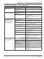
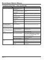
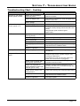
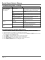
SECTION 7 - TROUBLESHOOTING GUIDE
Section 7 - Troubleshooting Guide
IMPORTANT
•
While this troubleshooting guide provides information to aid in troubleshooting problems with
the range, it does not contain information on every possible type of failure.
•
See Appendix A to determine when elements and convection fan should be on or off.
Control Panel Error Codes
The error codes below apply to both models ER36D and ER48D.
General Error Codes
The following codes give a general indication of the location of problems detected by the control panel
controller board. They are usually followed by another, more specific error code (see below).
ERROR CODE
GENERAL LOCATION
F1
INTERNAL
F2
COMMUNICATION BETWEEN CONTROL PANEL AND RELAY BOARD
F3
EXTERNAL
F9
DOOR LOCK
Specific Error Codes
ERROR CODE
POSSIBLE CAUSES
POSSIBLE SOLUTIONS
Shorted element relay.
Replace power board.
F10
Intermittent temperature sensor or loose
sensor wiring.
Tighten sensor connections for
replace temperature sensor.
F11
Shorted key (button) on keypad membrane. Replace keypad membrane.
F13
Control panel failure.
Replace power board.
F14
Defective power board.
Replace power board.
F15
Defective power board.
Replace power board.
F20
Data cable between relay board and control
panel loose or defective.
Tighten connections, replace if
necessary.
Defective control panel circuit board.
Replace control panel circuit board.
Shorted temperature sensor.
Replace sensor.
Shorted temperature sensor wiring.
Repair sensor wiring.
Open temperature sensor.
Replace sensor.
Open temperature sensor wiring.
Replace sensor wiring.
Data cable between relay board and control
panel loose or defective.
Tighten connections, replace if
necessary.
Defective membrane.
Replace membrane.
Cables to door latch loose or defective.
Tighten connections or repair cable.
Defective door latch assembly.
Replace door latch assembly.
Defective power board.
Replace power board.
F30
F31
F32
F90
F95
Page 7-1
DACOR RANGE SERVICE MANUAL
Basic Troubleshooting Instructions
1. If the range does not function properly, check for obvious problems first, such as the main power
switch being turned off, or the control panel being locked.
2. If the problem is not immediately obvious, use the Performance Tests in Appendix B and consult
the Troubleshooting Chart on the following pages to help locate the problem.
Troubleshooting Chart - Oven
PROBLEM
POSSIBLE CAUSES
WHAT TO CHECK
Nothing works, no power
to the range, control panel
display is dark, burners do
not spark, burner knobs
don’t light when turned
on.
Range not connected to • Conduit or appliance wire connection.
electrical power.
Oven will not heat.
Cooktop works OK. Control
panel lit. Oven controller
beeps when keys are
pressed.
Power to range is off.
• Tripped circuit breaker or blown fuse.
Power outage.
• Contact power company.
Wiring problems.
• Check wiring harness.
Oven setting not
correct.
• Press CANCEL/SECURE, then follow instructions in
Operating the Oven section of this manual.
Oven set for delay
timed cooking.
• Oven will turn on automatically at preset time. Press
CANCEL/SECURE to return to normal operation.
Attempting to broil with • Broil and convection broil settings will not work when
meat probe is connected. Disconnect meat probe.
meat probe connected.
Power board problems.
• Power board wiring.
• Power board.
Bad heating element.
• Check Cycling Chart (Appendix A) to determine
elements used during the mode that is not working.
Check continuity.
High limit switch
tripped or defective.
• Wires to high limit switch.
• High limit switch.
Oven does not heat,
display is lit. Cooktop
works OK. Control panel
does not beep when keys
are pressed.
Power board problems.
• Power board.
Control panel lockedup.
• Cycle power. Check range to see if normal operation
resumes.
Control panel
problems.
•
•
•
•
Oven does not heat,
display is not lit. Cooktop
works OK. Control panel
does not beep when keys
are pressed.
Power board problems.
• Wiring to power board
• Power board
Control panel lockedup.
• Cycle power. Check range to see if normal operation
resumes.
Control panel
problems.
•
•
•
•
Page 7-2
Cable from power board to oven controller board.
Oven controller board.
Cable from oven controller board to keypad membrane.
Keypad membrane.
Cable from power board to oven controller board.
Oven controller board.
Cable from oven controller board to keypad membrane.
Keypad membrane.
SECTION 7 - TROUBLESHOOTING GUIDE
Troubleshooting Chart - Oven (continued)
PROBLEM
Time on display not
correct.
Time flashes on display.
Oven does not selfclean. Display is lit.
Oven controller beeps
when keys are pressed.
Cooktop works OK.
Oven lights will not work.
Oven heats normally and
cooktop works OK.
POSSIBLE CAUSES
WHAT TO CHECK
Time of day not set.
• Set time.
Power failure or power was
turned off.
• Reset time.
Control panel problems.
• Oven controller board.
Power failure or power was
turned off.
• Reset time.
Control panel problems.
• Cable from power board to oven controller board.
• Oven controller board.
• Cable from oven controller board to keypad
membrane.
• Keypad membrane.
Door not shut tightly.
• Check for obstructions. Close door tightly.
Oven set for delay timed
cleaning.
• Oven will start to self-clean at preset time. Press
CANCEL/SECURE to return to normal operation.
Model ER48D only: Other
oven is on or self-cleaning.
• Due to power consumption on model ER48D, one
oven cannot self-clean while the other is in use or
self-cleaning. Turn off other oven.
Oven not set properly.
• Follow instructions in Cleaning and Maintenance
section.
Meat probe connected.
• Oven will not start self-clean cycle when meat probe
is connected. Disconnect and remove meat probe.
Door latch problems.
• Door latch wiring.
• Door latch and switches.
High limit switch tripped or
defective.
• Wires to high limit switch.
• High limit switch.
Power board problems.
• Power board wiring.
• Power board.
Control panel problems.
• Oven controller board.
• Cable from oven controller board to keypad
membrane.
• Keypad membrane (self-clean key).
Light bulbs burned out.
• Replace light bulbs. See Cleaning and Maintenance
section.
Oven in self-clean mode.
• Lights do not work when oven is in self-clean mode.
Light fixture/wiring
problems.
• Light wiring harness.
• Light fixture.
Light transformer.
• Wiring between transformer and power board.
• Transformer.
Power board problems.
• Wiring to power board.
• Power board.
Control panel problems.
• Oven controller board.
• Cable from oven controller board to keypad
membrane.
• Keypad membrane.
Page 7-3
DACOR RANGE SERVICE MANUAL
Troubleshooting Chart - Oven (continued)
PROBLEM
POSSIBLE CAUSES
Foods over or under cook. Incorrect cooking time or
temperature.
WHAT TO CHECK
• Follow instructions in Operating Instructions section.
Items not being cooked on
rack level that will provide
best results.
• See Understanding the Various Cooking Modes
section.
Food placed in oven during
pre-heat.
• Make sure pre-heat indicator on display is off before
putting food in oven (does not apply to broil modes).
Oven set to incorrect
temperature scale.
• See Setting the Temperature Scale section.
Relay stuck closed on
power board.
• Power board.
Defective temperature
sensor.
• Temperature sensor.
Elements not wired
correctly.
• Check for correct element wiring.
Cooling fan continues
to run after oven is
turned off. Shuts off after
extended period of time.
Normal operation.
• The cooling fan may run for a while after the oven is
turned off, until the internal parts have cooled.
Cooling fan runs
continuously after oven is
off and does not shut off
after an extended period
of time.
Power board problems.
• Power board.
Defective temperature
sensor.
• Temperature sensor.
Control panel problems.
• Cable from power board to oven controller board.
• Oven controller board.
Oven door will not open.
Oven is set to self-clean.
• Check display. If “LOCK” appears on display oven
door cannot be opened. Wait for oven to complete
self-clean or press CANCEL/SECURE. Door will
unlock once oven has cooled.
Door latch problems.
• Door latch wiring.
• Door latch and switches.
Power board problems.
• Power board.
Meat probe not plugged in.
• Make sure meat probe is plugged into meat probe
connector.
Meat probe defective.
• Check meat probe continuity.
Meat probe connector
problem.
• Wiring from meat probe to power board.
• Power board.
Meat probe does not
work.
Page 7-4
SECTION 7 - TROUBLESHOOTING GUIDE
Troubleshooting Chart - Cooktop
PROBLEM
Igniters do not spark.
Control panel is dark.
POSSIBLE CAUSES
WHAT TO CHECK
Range not connected to
electrical power.
• Have electrician connect range to properly wired
electrical connection.
Power to range is off.
• Turn power on at junction box. Check for tripped circuit
breaker or blown fuse.
Power outage.
• Contact power company.
Igniters do not spark.
Control panel is lit.
Wet or dirty igniter.
• Clean according to Cleaning and Maintenance section.
Spark module problems.
• Wiring between terminal blocks below access panel
and spark module (including switches mounted to the
valves).
• Wiring between spark module and igniter.
• Spark module.
No flame.
Igniter(s) not working (no
clicking sound).
• See igniters do not spark above.
Wet or dirty igniter.
• Clean according to Cleaning and Maintenance section.
Gas is turned off.
• Make sure the gas supply valve is in the on position.
Gas supply interrupted.
• Contact gas company.
Gas supply pressure too
low.
• Make sure gas supply to building meets the Gas Supply
Requirements in the installation section.
Defective regulator.
• Gas supply regulator.
LPG gas supply.
• Slightly yellow tips are normal for range equipped for
use with LPG.
Flame yellow at tips.
Large, erratic, or yellow Dirty burner assembly.
flame.
Burner ring or burner cap
not properly positioned.
• Make sure burner bases, burner heads, burner rings,
and burner caps are free of grease and grime. See
Cleaning and Maintenance.
• On stack burners, make sure the main orifice in the
bottom of the burner base is not plugged up.
• Make sure burner is assembled according to the
Installation Instructions section.
• Determine if range is properly equipped for type of
Range not equipped for
gas being used and for the correct altitude range. See
correct altitude or gas type
Model Identification section.
(natural gas or LPG).
Crown burner venturi out
of adjustment.
• Check venturi opening. See Component Repair section.
Low gas pressure.
• Make sure gas supply to building meets the Gas Supply
Requirements in the installation section.
Defective regulator.
• Gas supply regulator.
Page 7-5
DACOR RANGE SERVICE MANUAL
Troubleshooting Chart - Cooktop
PROBLEM
Igniter continues to
spark (click) after
flame ignites.
Flame goes out at low
setting.
Burner knob does not
light.
POSSIBLE CAUSES
WHAT TO CHECK
Burner is cold.
• Burners may continue to spark for up to 60 seconds
when cold and set to low. See Operating the Cooktop
section for more information on how to minimize.
Flame distorted by air
draft.
• Minimize any air drafts around the range. Close nearby
windows.
Wet or dirty igniter.
• Clean according to Cleaning and Maintenance section.
Burner ring or burner cap
is dirty.
• Clean according to Cleaning and Maintenance section.
Burner ring or burner cap
not properly positioned.
• Make sure burner is assembled according to the
Installation Instructions section.
Improper electrical
polarity.
• Electrical wiring reversed. See Electrical Connection in
Installation Instructions section.
Air intake holes
obstructed.
• Check to make sure air holes above knobs are not
blocked.
Low gas pressure.
• Make sure gas supply to building meets the Gas Supply
Requirements in the installation section.
LED harness problems.
• LED wiring harness connection.
• LED wiring harness wires open.
LED defective.
• LED continuity.
Accessing Software Version Information
To access to read the software versions loaded on the various printed circuit boards:
1. Disconnect power to the range for 20 seconds, then reconnect.
2. Within the first 30 seconds after power up, press and hold the BAKE and BROIL keys for at least
6-10 seconds to enter diagnostic mode.
3. Press START to read the EEPROM version on the control board.
4. Press PROBE to read the FLASH version on the control board.
5. Press SELF-CLEAN to read the software version on the power board.
6. Press CANCEL/SECURE twice to exit diagnostic mode.
Page 7-6
SECTION 8 - RANGE DISASSEMBLY
Section 8 - Range Disassembly
DANGER
•
Turn off electrical power at the main power supply and the gas supply at the gas supply valve
before servicing the range. Failure to turn off electrical power and the gas supply to the range
will result in a electric shock and explosion hazard.
Door Removal
WARNING
•
Do not attempt to disengage the hinge locks on the door while it is removed from the oven. The
hinge springs could release, causing personal injury.
•
Do not lift or carry the oven door by the door handle.
•
Open the oven door completely.
•
Pull the hinge locks forward on both hinges,
until they stop.
•
Raise the door so that it is at a 15° angle
from the front of the oven. Hold the door with
one hand on each side. Lift the door up and
out.
Page 8-1
DACOR RANGE SERVICE MANUAL
Door Installation
WARNING
•
Be sure that the notch on the bottom of each hinge rests on top of the lower lip of each hinge
receptacle before attempting to open the oven door. Failure to do so may cause the door to fall
off its hinges, resulting in personal injury or damage to the door.
•
Rotate the hinge locks toward the front of the range immediately after installation of the door.
Failure to do so may cause the door to fall off its hinges, resulting in personal injury or damage
to the door.
•
Grasp the oven door on opposite sides and
hold it at a 15° angle from the front of the
oven. Slide the hinges A into the hinge
openings B , resting the bottom of the hinge
arms C on the lower lip D of the hinge
receptacles. Continue to hold the door at a
15° angle with one hand while pushing in on
each of the bottom corners of the door. Push
until the notch E on the bottom of each
hinge slips over the lower lip D of each
hinge receptacle.
•
Lower the door to the fully opened position.
•
Rotate both hinge locks toward the oven.
•
Open and close the door completely to ensure
that it is properly installed.
B
A
E
D
C
Page 8-2
SECTION 8 - RANGE DISASSEMBLY
Removing the Back Panel
•
Turn off the gas supply at the gas supply
valve and power to the range at the junction
or fuse box.
•
Pull the range out from the wall or cabinet.
•
Remove the grates, the burner caps, burner
rings, and crown burner heads from the
cooktop.
•
If the range is equipped with a 24” backguard
F , remove the eight (8) backguard bracket
hex screws G . They are accessed through
the 8 holes H on the back of the backguard.
F
H
G
•
Remove the five (5) screws I on the front of
the island trim/backguard J , above the spill
trays K .
J
I
K
•
Remove the eight (8) screws on the back side
of the island trim/backguard, four (4) on each
side of the range.
Page 8-3
DACOR RANGE SERVICE MANUAL
Removing the Back Panel (continued)
•
Pull the island trim/backguard J up and off
the range.
•
Remove the stainless steel spill tray trim piece
L.
J
L
•
Remove the electrical access panel cover N
by removing the two (2) screws M that hold
it in place.
•
Remove the two (2) screws O on the
sides of the electrical access panel. It is not
necessary to remove the gas regulator access
panel cover P .
P
M
O
O
N
M
•
Remove all of the remaining screws from the
back panel and pull it off.
Page 8-4
SECTION 8 - RANGE DISASSEMBLY
Removing the Side Panel(s)
•
Turn off the gas supply at the supply valve
and power to the range at the junction or fuse
box.
•
Pull the range out from the wall or cabinet
•
Remove all of the screws from the edge of the
back panel A on the same side of the range
as the side panel being removed.
•
Loosen the end cap set screws B through
the access holes C on the bottom of the
front panel lip D .
A
B
D
C
•
Remove the end cap.
Page 8-5
DACOR RANGE SERVICE MANUAL
Removing the Side Panel(s) (continued)
•
Remove the side panel screw inside the front
panel lip.
•
Remove the grates, the burner caps, burner
rings, and crown burner heads from the
cooktop.
•
Remove the screws above the spill tray that
hold the side panel in place.
•
Lift the side panel off of the range.
Page 8-6
SECTION 8 - RANGE DISASSEMBLY
Removing the Spill Trays
CAUTION
•
Take care when disassembling the spill
tray. Many of the spill tray components
are porcelain coated and can chip.
E
•
Turn off the gas supply at the supply valve
and power to the range at the junction or
fuse box.
•
Remove the grates, the burner caps, burner
rings, and crown burner heads from the
cooktop.
•
Remove the spill tray trim screws, located
above the spill trays E , from the back,
front, and side panels.
•
Slip all four (4) spill tray trim pieces F that
were held in place by the screws out of the
side, front, and back panels G .
•
G
G
Use the thread ring removal tool H (Dacor
part# 101539, included with range, see
page 3-6 for location) to remove all four (4)
thread rings I from the crown burner bases
(eight [8] thread rings total).
F
NOTE
•
Dacor recommends using anti-seize
grease on the thread rings during
reassembly. Doing so will make future
disassembly easier.
G
H
I
I
Page 8-7
DACOR RANGE SERVICE MANUAL
Removing the Spill Trays (continued)
•
Remove the screws from the stack burner
heads H (eight [8] screws total).
H
•
Remove each of the stack burner heads.
When removing the head, disconnect the
igniter wire from each one.
•
Gently lift up on the back of one of the
porcelain trim pieces I where the spill trays
J come together. Pull it toward the back of
the range and out of the stainless steel trim
piece above the front of the spill tray. Be
careful not to chip the porcelain.
•
Repeat for the remaining porcelain trim piece.
•
To remove the spill trays, pull up on the
back of each spill tray and slip it out of the
stainless steel trim piece toward the front
of the range. Be careful not to chip the
porcelain.
Page 8-8
J
I
J
SECTION 9 - COMPONENT REPAIR
Section 9 - Component Repair
DANGER
•
Turn off electrical power at the main power supply and the gas supply at the supply valve
before servicing the range. Failure to turn off electrical power and the gas supply to the range
will result in a electric shock and explosion hazard.
Door Component Repair
WARNING
•
Do not attempt to disengage the hinge locks on the door while it is removed from the oven. The
hinge springs could release, causing personal injury.
•
Do not lift or carry the oven door by the door handle.
Door Gasket (seal)
•
Remove the oven door. See the Door Removal
section on page 8-1.
•
Lay the door on a flat, padded surface with
the door gasket A facing up.
•
Remove the gasket by grasping sections of it
and pulling up.
•
Insert the self-locking tabs on the
replacement gasket into the holes on the
oven door. Check to make sure that all of the
self-locking tabs are firmly in place by pulling
gently on the gasket.
•
Reinstall the oven door. See the Door
Installation section on page 8-2.
A
Door Handle (ER48D)
•
Remove the oven door. See the Door Removal
section on page 8-1.
•
Lay the door on a flat, padded surface with
the door gasket facing up.
•
Remove the two (2) screws B in the top
corners of the door.
•
Grasp the door with one hand and pull up.
Pull the door handle out from underneath.
•
To reinstall the door handle, grasp the door
with one hand and pull up. Hold the handle in
position on the front. Lower the door onto the
padded surface.
•
Replace the two (2) screws in the top corners
of the door and tighten into place. Do not
over-tighten the screws. The front door glass
could crack.
•
Reinstall the oven door. See the Door
Installation section on page 8-2.
B
B
Page 9-1
DACOR RANGE SERVICE MANUAL
Door Handle (ER36D)
•
Remove the oven door. See the Door Removal
section on page 8-1.
•
Lay the door on a flat, padded surface with the
door gasket facing up.
•
Remove the two (2) door handle screw
plugs X . The door handle mounting screws
are located below the plugs.
•
Remove the two (2) door handle screws Y .
Do not remove the door liner screws B .
•
Grasp the door with one hand and pull up. Pull
the door handle out from underneath.
•
To reinstall the door handle, grasp the door
with one hand and pull up. Hold the handle in
position on the front. Lower the door onto the
padded surface.
•
Replace the two (2) screws in the top corners
of the door and tighten into place. Do not
over-tighten the screws. The front door glass
could crack.
•
Reinstall the door handle screw plugs.
•
Reinstall the oven door. See the Door
Installation section on page 8-2.
Page 9-2
B
X
Y
B
X
Y
SECTION 9 - COMPONENT REPAIR
Door Component Repair (continued)
Front Door Glass Assembly
B
B
WARNING
•
To prevent personal injury, use gloves
when handling glass components that are
broken or shattered.
•
Remove the oven door. See the Door Removal
section on page 8-1.
•
Lay the door, handle down, on a flat, padded
surface with the door gasket facing up.
•
Remove the two (2) screws B in the top
corners of the door.
•
On ER48D Only: Grasp the top end of the
door with one hand and pull up. Pull the door
handle out from underneath.
•
Grasp the top of the door with both hands
and turn it over on the padded surface so that
the door gasket faces up.
•
Remove the two (2) inner screws C on the
bottom of the door. The outer screws D on
the bottom of the door are part of the hinge
assembly. Do not remove them.
C
C
C
D
•
Grab the front door glass assembly with both
hands and remove it.
•
On ER36D Only
y: Remove the two (2) door
handle screw plugs X . The door handle
mounting screws are located below the plugs
(see facing page). Remove the two (2) door
handle screws Y . Do not remove the door
liner screws B . Assemble the door handle to
the new front door glass assembly. Replace
the plugs
Page 9-3
DACOR RANGE SERVICE MANUAL
Door Component Repair (continued)
•
When putting the front door glass assembly
back in place, be careful not to knock loose
the door spacers which are glued to the top
corners. Also, make sure the tabs E on the
bottom rest on the outside of the door liner.
•
Reinstall the screws on the bottom of the
door, then grasp the top of the door with both
hands and turn it over.
•
On ER48D Only
y: Hold the top end of the door
up with one hand. Position the handle under
the door and lower the door on top. Replace
the handle screws. Do not over-tighten.
•
Reinstall the oven door. See the Door
Installation section on page 8-2.
E
Door Hinges
•
Remove the oven door. See the Door Removal
section on page 8-1.
•
Lay the door, handle down, on a flat, padded
surface with the door gasket facing up.
•
Remove the two (2) screws B in the top
corners of the door.
•
On ER48D Only
y: Grasp the top end of the
door with one hand and pull up. Pull the door
handle out from underneath.
•
Grasp the top of the door with both hands
and turn it over on the padded surface so that
the door gasket faces up.
•
Remove the two (2) inner screws C on the
bottom of the door. The outer screws D on
the bottom of the door are part of the hinge
assembly. Do not remove them.
B
B
C
C
C
D
Continued...
Page 9-4
SECTION 9 - COMPONENT REPAIR
Door Hinges (continued)
•
Grab the front door glass assembly with both
hands and remove it.
•
Remove the two (2) hinge cover screws F
over the hinge to be removed and pull off the
hinge cover G .
•
Remove the hinge retainer screw H for the
hinge to be removed.
G
G
F
F
F
F
H
H
•
Carefully pry up the hinge I up and out of
the door.
•
After installing the hinge, replace the hinge
cover and the three (3) screws that hold the
hinge assembly in place.
•
Reassemble the door. When putting the front
door glass assembly back in place, be careful
not to knock loose the door spacers which are
glued to the top corners. Also, make sure the
tabs E on the bottom rest on the outside of
the door liner.
•
Reinstall the screws on the bottom of the
door, then grasp the top of the door with both
hands and turn it over.
•
On ER48D Only: Hold the top end of the door
up with one hand. Position the handle under
the door and lower the door on top. Replace
the handle screws. Do not over-tighten.
•
Reinstall the oven door. See the Door
Installation section on page 8-2.
I
E
Page 9-5
DACOR RANGE SERVICE MANUAL
Door Component Repair (continued)
Inner Window Assembly
B
B
WARNING
•
To prevent personal injury, use gloves
when handling glass components that are
broken or shattered.
•
Remove the oven door. See the Door Removal
section on page 8-1.
•
Lay the door, handle down, on a flat, padded
surface with the door gasket facing up.
•
Remove the two (2) screws B in the top
corners of the door.
•
On ER48D only: Grasp the top end of the
door with one hand and pull up. Pull the door
handle out from underneath.
•
Grasp the top of the door with both hands
and turn it over on the padded surface so that
the door gasket faces up.
•
Remove the two (2) inner screws C on the
bottom of the door. The outer screws D on
the bottom of the door are part of the hinge
assembly. Do not remove them.
C
C
C
D
•
Grab the front door glass assembly with both
hands and remove it.
Page 9-6
SECTION 9 - COMPONENT REPAIR
Inner Window Assembly (continued)
•
Remove the four (4) screws J that hold the
outer heat shield K in place. Lift the outer
heat shield out.
K
J
J
J
J
•
Remove the four (4) screws L that hold the
lower outer heat shield M in place. Lift the
lower heat shield out.
M
L
L
L
L
•
Remove the four (4) screws N that hold the
inner heat shield O in place. Lift the inner
heat shield up and out toward the top of the
door.
O
N
N
•
N
N
Push the glass window assembly out of the
door liner from the bottom and lift it out.
Page 9-7
DACOR RANGE SERVICE MANUAL
Door Component Repair (continued)
•
If the inner widow gasket P must be
removed, make sure it is fit completely
into the groove around the window opening
before replacing the window assembly.
•
Replace the window glass assembly. The
seam in the metal rim around the inside of
the glass must be placed toward the top of
the door.
•
Replace the inner heat shield and tighten into
place using the existing screws.
•
Replace the lower outer heat shield and
tighten into place using the existing screws.
•
Replace the outer heat shield and tighten
into place using the existing screws.
•
Reassemble the door. When putting the front
door glass assembly back in place, be careful
not to knock loose the door spacers which
are glued to the top corners, loose. Also,
make sure the tabs E on the bottom rest on
the outside of the door liner.
•
Reinstall the screws on the bottom of the
door, then grasp the top of the door with
both hands and turn it over.
•
On ER48D only: Hold the top end of the door
up with one hand. Position the handle under
the door and lower the door on top. Replace
the handle screws. Do not over-tighten.
•
Reinstall the oven door. See the Door
Installation section on page 8-2.
Page 9-8
P
E
SECTION 9 - COMPONENT REPAIR
Cooktop Component Repair
General
To make repairs to the cooktop gas supply lines (flex tubes), remove the
spill trays. See page 8-7 for instructions. Each burner is fed by two (2)
flex tubes from the valve. The larger flex tube is the main gas supply
line. It supplies gas to the main orifice on each burner. The smaller
flex tube is the simmer line. It supplies gas to the simmer orifice on
each burner assembly. The simmer line supplies the low volume of gas
required to keep the burner lit at low flame levels.
See the schematic below for details on the routing of the various gas
lines.
Center Front
Center Rear
Right Rear
Left Rear
Left Front
Right Front
Left Manifold
Right Manifold
Tee: Located under spill tray
To external gas shut off
valve and gas supply line.
Simmer Orifice Lines (3/16”)
Main Orifice Lines (5/16”)
Manifold Lines (3/8”)
Regulator to Tee (5/8”)
Regulator: Behind back panel
COOKTOP GAS LINES
Page 9-9
DACOR RANGE SERVICE MANUAL
Cooktop Component Repair (continued)
Regulator
•
Turn off the gas supply at the supply valve
and power to the range at the junction or fuse
box.
•
Pull the range out from the wall or cabinet.
•
Remove the gas regulator access cover A
from the back of the range B .
•
Disconnect the gas supply line C to the
regulator D .
•
Disconnect the flex tube E from the top of
the regulator.
•
Hold the regulator in one hand while removing
the two (2) screws F from the regulator
bracket. Remove the regulator through the
access hole.
•
Reassemble the regulator in the reverse order.
•
Turn the gas supply on and check for leaks
using a gas leak detector or bubble forming
fluid.
•
Turn on the power at the junction or fuse
box. Test the cooktop for proper operation
according the installation instructions.
•
Turn off the power and gas supply. Reinstall
the gas regulator access cover.
•
Push the range back into position in the wall
or cabinet.
•
Turn on gas supply and power. Test the
cooktop to ensure that repairs were properly
completed.
Page 9-10
A
B
E
F
F
D
C
SECTION 9 - COMPONENT REPAIR
Cooktop Component Repair (continued)
Igniters and Orifices (injectors)
Replacement of the crown burner igniters or
orifices require the removal of the spill trays. The
spill trays do not need to be removed to replace
the stack burner igniters or orifices.
Stack Burner
•
Turn off the gas supply at the supply valve
and power to the range at the junction or fuse
box.
•
Remove the grates.
•
Remove the burner ring and burner cap from
the stack burner.
•
Remove both T20 Torx head screws from the
top of the stack burner base G .
•
Remove the burner head. Slip the igniter wire
H off of the igniter I as you remove it.
G
G
I
H
Stack burner igniter replacement
•
The stack burner igniter is mounted to the
side of the stack burner base. Pry the retainer
ring J at the bottom of the igniter spring K
off the igniter L .
•
Pull the igniter out of the burner base.
•
Reattach the igniter to the base.
L
K
J
Page 9-11
DACOR RANGE SERVICE MANUAL
Cooktop Component Repair (continued)
Stack burner orifice replacement
•
Use a 7 mm hex driver or socket to remove
the orifice from the burner base. The main
orifice M is located in the center of the
burner. The simmer orifice N is located near
the outside of the base. Consult the Dacor
technical service department for the correct
orifice size. The size of each orifice is stamped
on its side.
•
Tighten the replacement orifice into place with
the 7 mm hex tool.
•
Repeat the above steps for any other stack
burners that need to be serviced.
M
N
Crown Burner
•
Turn off the gas supply and power to the
range at the junction or fuse box.
•
Remove the spill trays. See the Removing the
Spill Trays section on page 8-7.
Q
Crown burner igniter replacement
•
The crown burner igniter is mounted in the
crown burner base. Pry the retainer ring O
at the bottom of the igniter spring P off the
igniter Q .
•
Slip the igniter wire off and pull the igniter
out of the burner base.
•
Reattach the igniter to the base in the reverse
order.
P
O
Crown burner orifice replacement
Consult Dacor technical service department for
the correct orifice sizes. The size of each orifice is
stamped on its side.
•
The main orifice R on the crown burner
is located at the end of the venturi tube
assembly S . Use a 7 mm hex wrench to
remove and install the orifice.
S
R
Page 9-12
SECTION 9 - COMPONENT REPAIR
Crown burner orifice replacement
(continued)
•
The simmer orifice is attached to a fitting on
the side of the crown burner. Remove the
fitting retaining clip T to access the simmer
orifice fitting.
•
Pull the fitting U out of the side of the
burner.
•
Use a 7 mm hex wrench to remove the
simmer orifice V from the fitting.
•
Tighten the replacement orifice into place with
a 7 mm hex wrench.
•
Repeat the above steps for the other crown
burner if it requires service.
T
Venturi Adjustment
For proper operation, the gap between the end of
the crown burner main orifice R and the end of
the venturi X needs to be set to 9 mm.
•
•
U
To adjust the venturi gap, loosen the
set screw W on the side of the venture
assembly.
V
Slide the venturi in and out of the venturi
assembly to adjust the gap.
After Burner Service is Complete:
•
Reinstall the spill trays.
•
Reattach the igniter wires to the stack burner
igniters.
•
X
Reassemble the cooktop and test it to ensure
that repairs were properly completed.
W
R
Page 9-13
DACOR RANGE SERVICE MANUAL
Cooktop Component Repair (continued)
Igniter Module
•
Turn off the gas supply and power to the
range at the junction or fuse box.
•
Remove the spill trays. See the Removing the
Spill Trays section on page 8-7.
•
Determine the igniter to be replaced by
tracing the igniter wire G from the burner
that is not sparking back to the module H
. The igniter modules are located under the
igniter module insulation I .
•
I
G
J
Disconnect the igniter wire and power supply
wires J from the module.
•
Remove the screws that hold the module to
the chassis.
•
Install the new module, reconnect the wire
and replace the insulation.
•
Reassemble the cooktop and test it to make
sure that it has been reassembled properly.
H
Knob Lights (LED assembly)
•
Turn off the gas supply and power to the
range at the junction or fuse box.
•
Remove the spill trays. See the Removing the
Spill Trays section on page 8-7.
•
Pull off the knob in front of the LED assembly
to be removed. Doing so will make it easier to
see the LED assembly from the back side.
The LED is held in place by the LED holder A
above the valve stem B .
•
To remove the LED, push in on the LED gently
with your finger. Then reach in from the back
side of the cooktop front panel C and pull
back on the wires connecting to the LED.
•
Disconnect the LED assembly D at the
connector E about six (6) inches from the
LED.
•
When remounting the LED, push the LED into
the LED holder from the back side until it
stops.
•
Replace the knob.
•
Reassemble the cooktop and test it to make
sure the LED is working and that the cooktop
has been reassembled properly.
Page 9-14
C
A
B
C
D
E
SECTION 9 - COMPONENT REPAIR
Cooktop Component Repair (continued)
Manifolds and Valves
•
Turn off the gas supply and power to the
range at the junction or fuse box.
•
Remove the spill trays. See the Removing the
Spill Trays section on page 8-7.
•
Remove the torx head screws from the end
caps F through the access holes G on the
bottom of the front panel lip H .
•
Remove the end cap.
•
Pull the all the knobs off the front of the
range.
•
Remove the side panel screw inside the front
panel lip.
•
Remove the screws from the bottom of the
cooktop front panel C .
F
H
G
C
Page 9-15
DACOR RANGE SERVICE MANUAL
Cooktop Component Repair (continued)
•
Make sure the oven control panel I is in the
lowered position. See page 5-2.
•
Pull the bottom of the front panel J out and
lift it up and off the range.
I
J
•
Remove all of the screws that hold the
channel support K to the cooktop chassis.
Lift the channel support out of the chassis.
•
Disconnect the wires L from the valves
connected to the manifold M to be removed.
•
Disconnect the flex tubes N from the valves
and the manifold to be removed.
•
Remove the nuts that attach the manifold
assembly to the sub-panel O .
K
N
M
L
O
Page 9-16
SECTION 9 - COMPONENT REPAIR
Manifolds and Valves (continued)
•
•
To remove the valves P , remove the bolts Q
from the bottom of the manifold R .
P
After repairs are completed, reassemble the
cooktop and test it to make sure repairs were
properly completed.
R
Q
Oven Component Repair
Smoke Eliminator
•
Turn off the gas supply at the supply valve
and power to the range at the junction or fuse
box.
•
Remove the oven door as described on page
8-1.
•
Remove the oven racks.
•
Remove the convection filter from the back
wall of the oven by lifting it up and out.
•
Remove the four (4) screws that hold the
convection baffle A to the back of the oven
B and remove it.
•
Model ER48D Only: If removing the smoke
eliminator for the left oven, remove the
screws that hold the broil element C to the
ceiling and slowly remove it. Pull the wires
through the back wall with a gentle rocking
motion to prevent them from disconnecting
from the element inside the back wall.
Disconnect the wires from the element after
they have pulled through the wall.
B
A
C
Page 9-17
DACOR RANGE SERVICE MANUAL
Oven Component Repair (continued)
The oven chamber smoke eliminator D is
located on the ceiling of the oven chamber near
the back. Exact location varies with model.
•
Remove the three (3) screws that hold the
smoke eliminator in place. Be careful not
to scratch the back of the oven with the
screwdriver during removal and installation.
•
To install the smoke eliminator, fasten it in
place with the three (3) existing screws.
•
Reinstall the broil element if necessary.
•
Reinstall the convection baffle. The end with
the slots on the side goes up.
•
Reinstall the convection filter.
•
Reinstall the oven racks.
•
Reinstall the oven door as described on page
8-2.
•
Test the oven to ensure that repairs were
properly completed.
Page 9-18
D
SECTION 9 - COMPONENT REPAIR
Oven Component Repair (continued)
Convection Element, Fan and Fan
Motor
•
Turn off the gas supply and power to the
range at the junction or fuse box.
•
Remove the oven racks from the oven.
•
Remove the oven door(s) as described on
page 8-1.
•
Remove the convection filter from the back
wall of the oven by lifting it up and out.
Q
Convection Baffle Removal
•
Remove the four (4) screws that hold the
convection baffle P in place. The screws are
located near the four corners of the baffle at
the back Q of the oven.
•
Remove the convection baffle.
P
Convection Element Removal
•
Remove the back panel as described on page
8-3.
•
Disconnect the convection element wires R
from the element behind the back panel.
•
Remove the three (3) screws S holding the
convection element T in place.
•
Grasp the convection element near the top
and pull it slowly out of the back wall with a
gentle, rocking motion.
•
Replace and reconnect the convection element
in the reverse order.
R
R
S
S
T
S
Page 9-19
DACOR RANGE SERVICE MANUAL
Oven Component Repair (continued)
Convection Fan and Fan Motor Removal
•
To remove the convection fan U , hold it with
one hand and turn the nut V clockwise with
a wrench.
•
With the back cover removed (see page 8-3),
label the location of the convection fan wires
W and disconnect them.
•
Remove the three (3) screws X that attach
the motor Y to the back panel to remove it
•
Reassemble the fan motor and fan in the
reverse order. When replacing the fan, make
sure that the washer is installed behind the
fan blade before installing the fan. Use a
wrench to tighten the nut counterclockwise.
•
Reinstall the four (4) mounting screws that
hold the baffle in place.
•
Reinstall the convection filter.
•
Reinstall the racks.
•
Reinstall the oven door as described on page
8-2.
•
Test the oven to ensure that repairs were
properly completed.
V
U
W
W
S
X
X
X
Page 9-20
SECTION 9 - COMPONENT REPAIR
Oven Component Repair (continued)
Broil Element
Left oven on Model ER48D:
•
Turn off the gas supply at the supply valve
and power to the range at the junction or fuse
box.
•
Remove the oven door as described on page
8-1.
•
Remove the oven racks.
•
Remove the convection filter E from the
back wall of the oven by lifting it up and out.
•
Remove the four (4) screws that hold the
convection baffle A to the back of the oven
and remove it.
•
Remove the screws that hold the broil
element C to the ceiling and slowly remove
it. Pull the wires through the back wall with
a gentle rocking motion to prevent them
from disconnecting from the element inside
the back wall. Disconnect the wires from the
element after they have pulled through the
wall.
•
When replacing the element, connect the
wires to the element and gently push them
into the holes on the back oven wall as you
reposition the element. Reattach it using the
existing screws.
•
Reinstall the convection baffle and filter.
•
Reinstall the oven racks.
•
Reinstall the oven door as described on page
8-2.
•
Test the oven to ensure that repairs were
properly completed.
C
A
E
Broil Element for Right Oven on Model
ER48D and Oven on Model ER36D:
•
Turn off the gas supply and power to the
range at the junction or fuse box.
•
Remove the oven door as described on page
8-1.
•
Remove the oven racks.
•
While holding the broil element assembly F
in place with one hand, remove the screws
that hold it in place.
•
Gently lower the broil element out of the
ceiling of the oven chamber.
F
Page 9-21
DACOR RANGE SERVICE MANUAL
Oven Component Repair (continued)
•
Label the wires G that connect to the broil
element terminal.
•
Gently remove the broil element wires from
the terminal block H on the broil element
assembly.
G
H
•
Place the broil element assembly on a flat,
padded surface and remove the screws from
each of the four (4) corners.
•
The broil element assembly separates into
three (3) components, the broil element
I , the broil element frame J , and the broil
element glass K .
•
To reassemble the broil element assembly,
use the four (4) existing screws. Insert the
broil element glass into the frame with the
smooth side down. Insert the broil element
with the ribbon wire L down and line up the
terminals H ,with the terminal cut-out M in
the frame.
I
K
L
M
J
Page 9-22
H
SECTION 9 - COMPONENT REPAIR
Broil Element (continued)
•
Place the broil element into the oven chamber
with the glass facing down and the terminals
toward the back of the oven.
•
Lift the back of the element up and reconnect
the broil element wires to the terminals
on the broil element assembly. Make sure
that the wires are connected to the proper
terminals.
•
Insert the broil element assembly into the
hole in the oven ceiling while pushing the broil
element wires into the access hole toward the
back.
•
Hold the broil element assembly in place
with one hand while replacing the eight (8)
existing screws that hold it in place.
•
Reinstall the racks.
•
Reinstall the oven door as described on page
8-2.
•
Test the oven to ensure that repairs were
properly completed.
Bake Element
Left oven on Model ER48D:
•
Turn off the gas supply at the supply valve
and power to the range at the junction or fuse
box.
•
Remove the oven door as described on page
8-1. Remove the oven racks.
•
Remove the convection filter A from the
back wall of the oven by lifting it up and out.
•
Remove the four (4) screws that hold the
convection baffle B to the back of the oven
and remove it.
•
Remove the screws that hold the bake
element C in place. Pull the wires through
the back wall with a gentle rocking motion
to prevent them from disconnecting from the
element inside the back wall. Disconnect the
wires from the element after they have pulled
through the wall.
•
When replacing the element, connect the
wires to the element and gently push them
into the holes on the back oven wall as you
reposition the element. Reattach it using the
existing screws.
•
Reinstall the convection baffle and filter.
•
Reinstall the oven racks. Reinstall the oven
door as described on page 8-2.
•
Test the oven to ensure that repairs were
properly completed.
A
B
C
Page 9-23
DACOR RANGE SERVICE MANUAL
Oven Component Repair (continued)
Broil element for right oven on Model ER48D
and oven on Model ER36D:
•
Turn off the gas supply at the supply valve
and power to the range at the junction or fuse
box.
•
Remove the oven door as described on page
8-1.
•
Remove the oven racks.
•
Remove the screws that hold the bake
element frame D in place on the floor of the
oven.
•
Remove the bake element frame and
glass E .
•
If replacing the bake element F , pull it up
and out of the floor of the oven.
D
E
•
Label the wires that connect to the bake
element terminals G . When reconnecting the
wires, make sure that the wires are connected
to the proper terminal.
•
If replacing the bake element glass, make
sure that the smooth side of the glass is
facing up when placing it in the oven.
•
When reassembling the bake element in the
floor of the oven, place the bake element
glass inside the bake element frame and place
it over the top of the bake element in the
floor of the oven.
•
Hold the bake element frame in place with
one hand while replacing the eight (8)
existing screws that hold it in place.
•
Reinstall the racks.
•
Reinstall the oven door(s) as described on
page 8-2.
•
Test the oven to ensure that repairs were
properly completed.
Page 9-24
F
G
SECTION 9 - COMPONENT REPAIR
Oven Component Repair (continued)
Temperature Sensor and Rack
Support
The following applies to all ER36D and
ER48D ovens, including the left oven on
model ER48D:
•
Turn off the gas supply at the supply valve
and power to the range at the junction or fuse
box.
•
Remove the oven door as described on page
8-1.
•
Remove the oven racks from the oven
chamber.
•
Remove the four (4) screws that hold the
right rack support H in place. Be careful not
to scratch the inside surface of the oven when
removing it.
•
Remove the two (2) screws that hold the
temperature sensor I in place. Be careful
not to scratch the baffle when removing the
screws.
•
When removing the temperature sensor,
pull the wires attached to the sensor gently
toward you through the hole in the back of
the oven to expose the connector. Do not
pull hard on the wires because the connector
may come loose inside the oven wall. Use
a screwdriver, if necessary, to move the
insulation around behind the hole to allow the
connector to slide out into the oven chamber.
•
Disconnect the temperature sensor wires at
the connector J to remove it. Connect the
replacement temperature sensor.
•
When reinstalling the temperature sensor,
gently push the connector and excess wire
through the access hole and insulation at the
back of the oven.
•
H
I
J
Tighten the temperature sensor into place
with the two (2) existing mounting screws.
Page 9-25
DACOR RANGE SERVICE MANUAL
Oven Component Repair (continued)
Reinstalling the Rack Support:
CAUTION
•
To prevent damage to the oven wall,
insert the rack support carefully.
•
Insert one end of the rack support into the
oven at a 20° angle to the sidewall.
•
Rotate the rack support into place, matching
the four (4) protruding pins on the rack
support to the holes in the oven wall.
•
Mount the rack support in place using the four
(4) existing screws.
•
Reinstall the racks and the oven door as
described in section 8.
•
Test the oven to ensure that repairs were
properly completed.
Light Fixtures and Meat Probe
NOTE
•
On model ER48D: There is no meat probe
connector on the left oven.
•
The rack support does not need to be
removed to service the meat probe
connector.
•
Turn off the gas supply at the supply valve
and power to the range at the junction or fuse
box.
•
Remove the oven door as described on page
8-1.
•
Remove the oven racks from the oven
chamber.
•
Move the range out from the wall and remove
the right side panel according to page 8-5.
•
Remove the four (4) screws that hold the
right rack support H in place. Be careful not
to scratch the inside surface of the oven when
removing it.
Page 9-26
H
SECTION 9 - COMPONENT REPAIR
Oven Component Repair (continued)
Light Fixtures and Meat Probe
(continued)
•
•
Remove all the mounting screws from the
intake grill K . The screws attach the grill to
the underside of the cooktop front panel I
and the top of the oven chambers(s) J .
Remove the intake grill.
I
J
K
Meat Probe Connector Removal
•
Using a 3/8” nut driver, remove the nut L
that holds the meat probe socket in place.
•
Push the meat probe socket through the
insulation and wire access hole in the wall of
the oven. Use a screwdriver, if necessary, to
move the insulation around behind the hole
to allow the socket to pass through to the
outside of the oven chamber.
•
Trace the meat probe wire up the side of
the range into the space M above the oven
chamber. Find the connector on the wire
inside, disconnect it and pull the meat probe
connector assembly out of the range.
•
Install the new meat probe connector in place
of the old one.
L
M
Page 9-27
DACOR RANGE SERVICE MANUAL
Oven Component Repair (continued)
Light Fixture Removal
CAUTION
•
Use the lens pry stick with caution. Do
not cause uneven stress on the lens.
•
Do not touch halogen light bulbs with
your hand. Hand oils left on the bulb will
cause early failure.
•
Trace the light fixture wire up into the
space M above the oven chamber. Find the
connector on the wire inside, and disconnect
it.
•
Gently insert the pointed end of the lens pry
stick (Dacor Part No. 62974), supplied with
the range, under the center edge of the lens.
Hold your hand under the lens for support,
then pull it straight out.
•
Using a glove, pull the light bulb straight out
of the light socket (do not turn).
•
Pull the light fixture out of the hole in the side
of the oven, pulling the wire and connector
with it. Use a screwdriver, if necessary, to
move the insulation around behind the hole
to allow the connector to slide out of the wall
into the oven chamber.
•
Gently push the connector and wire attached
to the replacement light fixture through the
hole and insulation in the wall of the oven.
Use a screwdriver, if necessary, to move the
insulation around behind the hole to allow the
connector to pass through to the outside of
the oven chamber.
•
Route the light fixture wire into the space
above the oven chamber and reconnect it.
•
Using a glove, insert the bulb into the
replacement light fixture socket. If replacing
the bulb, use only Dacor light bulb Part No.
100429. Using a screwdriver, pry the locking
tabs opposite socket of the old light fixture
out. Prying the tabs out will allow the fixture
to be removed from the oven wall.
•
Reinstall the lens cover by aligning the cover
over the opening and gently pressing it into
its original position. Be sure that the side of
the lens cover with the cutout lines up with
the light socket.
Page 9-28
M
SECTION 9 - COMPONENT REPAIR
Light Fixtures and Meat Probe
(continued)
Reinstalling the Rack Support:
•
Insert one end of the rack support into the
oven at a 20° angle to the sidewall.
•
Rotate the rack support into place, matching
the four (4) protruding pins on the rack
support to the holes in the oven wall.
•
Mount the rack support in place using the four
(4) existing screws.
•
Reinstall the racks and the oven door as
described in section 8.
•
Test the oven to ensure that repairs were
properly completed.
Door Latch and High Limit Switch
•
Turn off the gas supply at the supply valve
and power to the range at the junction or fuse
box.
•
Remove the oven door as described on page
8-1.
•
Remove the oven racks from the oven
chamber.
•
Remove all the mounting screws from the
intake grill K . The screws attach the grill to
the underside of the cooktop front panel I
and the top of the oven chambers(s) J .
•
Remove the intake grill.
•
Label and disconnect the wires from the door
latch or high limit switch as necessary.
•
Use a ratchet to remove the sheet metal
screws that hold the door latch A or high
limit switch B in place. The door latch is held
in place by four (4) screws. The high limit
switch is held in place by two (2) screws.
•
Reconnect the wires to the door latch or high
limit switch after mounting the replacement.
•
Reinstall the racks and the oven door as
described in section 8.
•
I
J
K
A
B
Test the oven to ensure that repairs were
properly completed.
Page 9-29
DACOR RANGE SERVICE MANUAL
Oven Component Repair (continued)
Cooling Fan Assembly Repair
•
Turn off the gas supply at the supply valve
and power to the range at the junction or fuse
box.
•
Move the range out from the wall or cabinet
and remove the back panel as described on
page 8-3.
•
The cooling fan assembly D is mounted to
the exhaust duct cover. Remove the screws
from the exhaust duct cover E to access the
cooling fan assembly. Do not remove the fan
mounting screws X .
•
Label and disconnect the wires F from the
cooling fan motor as you remove the cooling
fan assembly for service.
•
Reassemble the cooling fan and duct
assemblies in reverse order.
•
Replace the back cover.
•
Test the oven to ensure that repairs were
properly completed.
D
E
F
X
Page 9-30
SECTION 9 - COMPONENT REPAIR
Oven Component Repair (continued)
Power Board and Lighting Transformer
CAUTION
•
The printed circuit board assemblies in this range contain electronic components that are
sensitive to electrostatic discharge (ESD). Wear a properly grounded antistatic wrist strap when
handling or servicing the printed circuit assemblies. Insert the ESD sensitive circuit boards into
antistatic bags before placing them on any surface other than the oven chassis.
•
Turn off the gas supply at the supply valve
and power to the range at the junction or fuse
box.
•
Remove the spill trays as described starting
on page 8-7.
•
Remove the relay board cover G on the floor
of the cooktop chassis.
•
The power board H and the lighting
transformer I are mounted to the chassis
inside the relay board cover.
•
Label and disconnect any wires that are
disconnected from the power board or
transformer before repair or replacement.
•
Reassemble the range in the reverse order
and test the oven to ensure that repairs were
properly completed.
G
H
I
Page 9-31
DACOR RANGE SERVICE MANUAL
Oven Component Repair (continued)
CAUTION
•
The printed circuit board assemblies in this range contain electronic components that are
sensitive to electrostatic discharge (ESD). Wear a properly grounded antistatic wrist strap when
handling or servicing the printed circuit assemblies. Insert the ESD sensitive circuit boards into
antistatic bags before placing them on any surface other than the oven chassis.
Control Panel Repair
Follow these instructions to access the
controller board, keypad membrane and
mounting hardware.
•
Turn off the gas supply at the supply valve
and power to the range at the junction or fuse
box.
•
Remove the spill trays as described starting
on page 8-7.
•
Remove the torx head screws from the end
caps A through the access holes B on the
bottom of the front panel lip C .
•
Remove the end cap.
•
Remove the side panel screw inside the front
panel lip.
Page 9-32
A
C
B
SECTION 9 - COMPONENT REPAIR
Control Panel Repair (continued)
•
Remove the screws from the bottom of the
cooktop front panel D .
•
Make sure the oven control panel E is in the
lowered position. See page 5-2.
•
Pull the bottom of the front panel F out and
lift it up and off the range.
D
E
F
•
Remove all of the screws that hold the
channel support G to the cooktop chassis.
Lift the channel support out of the chassis.
G
Page 9-33
DACOR RANGE SERVICE MANUAL
Oven Component Repair (continued)
•
To remove the control panel assembly H
for service, remove the nuts that hold the
assembly to the sub panel I .
•
Label and disconnect any wires that are
disconnected from the controller board
or keypad membrane before repair or
replacement.
•
Reassemble the range in the reverse order
and test the oven to ensure that repairs were
properly completed.
I
H
Page 9-34