1
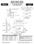
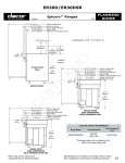
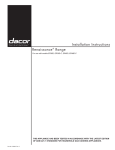
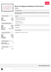
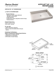
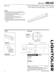
ER36D, ER48D
Epicure® Ranges
Revised
03/10/09
1/2
PLANNING
GUIDE
All tolerances: +/- 1/16” (+/- 1.6mm) unless otherwise stated
48” (1219mm)
ELECTRIC CIRCUIT REQUIREMENTS
Total Connected Load
Range Model
Circuit Required
ER36D
240 Vac, 4-wire* 60 Hz,
30 Amp. (Min.) 40 Amp.
(Recommended)
6.5 kW (28 Amp.)
ER48D
240 Vac, 4-wire* 60 Hz,
50 Amp.
10.0 kW (42 Amp.)
**
**
* 4-wire, two 120 Vac hot (L1 and L2), one neutral, one ground
1 1/16” (27mm) to cooking
surface (top of grates) from
top of trim
**
GAS SUPPLY PRESSURE REQUIREMENTS*
Gas Type
Manifold Pressure
Minimum Gas
Supply Pressure
Natural Gas
5” Water Column
6” Water Column
Propane (LP)
10” Water Column
11” Water Column
Finished Side
Panel
** Optional
* Maximum gas supply pressure 1/2 p.s.i. for all models
Width: ER36D - 35 7/8” (911mm)
Gas Regulator Access,
Cover Removed
ER48D - 47 7/8” (1216mm)
Range Electrical Access,
Cover Removed
GAS - ELECTRICAL ACCESS DIMENSIONS
Model
A
B
C
D
E*
ER36D
5 5/8”
(142.9mm)
18 3/8”
(466.7mm)
10 3/4”
(273.0mm)
13 11/16”
(347.7mm)
7/8”
(22.2mm)
3 13/16”
(96.8mm)
18 11/16”
(474.7mm)
9 3/8”
(238.1mm)
13 3/4”
(349.3mm)
1 1/8”
(28.6mm)
ER48D
A
C
NOTES:
Web: http://www.Dacor.com
Corporate Phone: 800-793-0093
Back of Range
B
D
* The diameter on models equipped for use in Canada is ¼”
(6.4mm) larger than those stated. Canadian units come from
the factory pre-wired with an appliance cord. When installing an
appliance cord on models that are not pre-wired, the hole size must
be increased to 1 1/8” (1 3/8” for model ER48D) by removing the
conduit bracket inside the range electrical access box.
1. When installing a backguard, always install it
before sliding the range into place.
Inlet
E Electrical Connection
Hole in Bottom
warning
◊
Observe all governing codes and ordinances during
planning and installation. Contact your local building
department for further information.
◊
This appliance must be installed in accordance with the
accompanying installation instructions.
Specifications are subject to change without notice.
See installation instructions for additional details.
5.15
ER36D, ER48D
Epicure® Ranges
Revised
03/10/09
2/2
PLANNING
GUIDE
Tolerances: +1/16”, -0, (+1.6mm, -0) unless otherwise stated
Gas and Electrical Service
F
13” (330mm)
Max.5
2, 5
◊
For replacement purposes, the location of the existing utilities
may be utilized provided they do not interfere with the sides or
rear of the range. Check local building codes for permissible
locations.
◊
An external manual shut-off valve must be installed between
the gas inlet and the range, for the purpose of turning on or
shutting off gas to the appliance.
The installation must allow for the following:
Non-combustible
surface along
back wall
recommended
30” (762mm)
G
Min.1
◊
Access to the gas shut-off valve when the unit is installed.
◊
Access to the remote circuit breaker panel/fuse box, when the
range is in place.
◊
The gas supply piping and shut-off valve, and the electrical
junction box/receptacle must be located so they do not
interfere with the range when it is installed.
◊
The junction box and gas shut off valve must be located so
that the range can be pulled out for service while the appliance
remains connected.
3
Suggested
location of
utilities4
36 1/2”
(927mm)
Max.
1
Vertical to combustibles directly above cooking surface;
if installing an overhead vent hood, also check the hood
specifications for minimum required clearances.
2
Measured from range top panel.
3
Cabinet/countertop depth is at discretion of customer but
cabinet face MUST NOT protrude further than rear of front
panel, see product dimensions.
4
Consult local code for exact location requirements.
5
Not applicable for cabinets more than a horizontal
distance of 10” (254mm) from the edge of the range.
Backsplash
Minumum Countertop Height:
30 1/4” (768 mm)
Maximum Countertop Height:
36 1/2” (927 mm)
non-combustible
rear wall recommended
3/8" (10 mm)
Min. flat countertop
overhang
CUT-OUT DIMENSIONS
Range Model
“F”
“G”
“H”
ER36D
42” (1067mm)*
36” (914mm)**
36 1/16”
(916mm)**
33 1/2”
(848mm)
ER48D
54” (1372mm)*
48” (1219mm)**
48 1/16”
(1221mm)**
43 1/2”
(1102mm)
* Recommended
**Minimum
2 13/16"
(71.4 mm)
3/8” Min. (10 mm)
flat countertop overhang
required behind cutout
H
Countertop*
Stiffener
10" (254 mm) Min.
3
to combustible side
walls above the range
(both sides)
3/8” Min. (10 mm)
space behind
raised vent
chassis to clear
stiffener
Cabinet face**
Back of
control
panel
ER36D or ER48D Range
ERV36-ER or
ERV48-ER
raised vent
Countertop height:
30 1/4" (768 mm) Min.
36 1/2” (927 mm) Max.
G
Cutout with optional erv raised vent
(top view)
APPROVED RAISED VENT MODELS
Raised Vent Model
For use with
Range Model
ERV36-ER
ER36D
ERV48-ER
ER48D
Web: http://www.Dacor.com
Corporate Phone: 800-793-0093
* IMPORTANT: See “CUTOUT WITH OPTIONAL ERV RAISED VENT”
for countertop cutout dimensions.
** IMPORTANT: Cabinet face must not stick out further than
back of control panel.
Raised vent installation side view
Specifications are subject to change without notice.
See installation instructions for additional details.
5.16