1
OmniViewIP* 5000HQ
User Manual
8820-00058 F1DP101C
*OmniView is a registered trademark of Belkin International, Inc.
Table of Contents
Table of Contents
sections
1
2
3
4
5
6
7
8
9
1 Introduction���������������������������������������������������������������������������������������� 1
11
12
13
14
15
16
17
18
19
20
21
6.3 Access Permissions tab . . . . . . . . . . . . . . . . . . . . . . . . . . . . . . . . 17
6.4 Saving a user . . . . . . . . . . . . . . . . . . . . . . . . . . . . . . . . . . . . . . . . . 18
6.4.1 Deleting a user . . . . . . . . . . . . . . . . . . . . . . . . . . . . . . . . . . . . . . . 18
6.5 Creating a user group . . . . . . . . . . . . . . . . . . . . . . . . . . . . . . . . . . 19
6.5.1 Access Permissions tab . . . . . . . . . . . . . . . . . . . . . . . . . . . . . . . 20
6.5.2 Allowed Services tab . . . . . . . . . . . . . . . . . . . . . . . . . . . . . . . . . 20
6.5.3 Saving the new group . . . . . . . . . . . . . . . . . . . . . . . . . . . . . . . . . 21
6.5.4 Deleting a user group . . . . . . . . . . . . . . . . . . . . . . . . . . . . . . . . . 21
1.1 Key features . . . . . . . . . . . . . . . . . . . . . . . . . . . . . . . . . . . . . . . . . . . 1
1.2 System components . . . . . . . . . . . . . . . . . . . . . . . . . . . . . . . . . . . . 2
1.3 Terminology . . . . . . . . . . . . . . . . . . . . . . . . . . . . . . . . . . . . . . . . . . . 2
1.4 System diagram . . . . . . . . . . . . . . . . . . . . . . . . . . . . . . . . . . . . . . . . 2
2 Pre-Installation Guidelines . . . . . . . . . . . . . . . . . . . . . . . . . . . . . . . 3
2.1 Access Services details . . . . . . . . . . . . . . . . . . . . . . . . . . . . . . . . . . 4
2.1.1 Adding user-defined Access Services . . . . . . . . . . . . . . . . . . . . . 4
7 Configuring Targets . . . . . . . . . . . . . . . . . . . . . . . . . . . . . . . . . . . . 22
7.1 Access Services tab . . . . . . . . . . . . . . . . . . . . . . . . . . . . . . . . . . . . 23
7.1.1 Default Access Service . . . . . . . . . . . . . . . . . . . . . . . . . . . . . . . . 23
7.1.2 Belkin OmniView KVM Switch . . . . . . . . . . . . . . . . . . . . . . . . . . . 24
7.2 PDU tab . . . . . . . . . . . . . . . . . . . . . . . . . . . . . . . . . . . . . . . . . . . . . . 26
7.3 Target Sets tab . . . . . . . . . . . . . . . . . . . . . . . . . . . . . . . . . . . . . . . . 28
7.4 Access Permissions tab . . . . . . . . . . . . . . . . . . . . . . . . . . . . . . . . . 28
7.5 Saving the target . . . . . . . . . . . . . . . . . . . . . . . . . . . . . . . . . . . . . . 29
7.6 Deleting targets . . . . . . . . . . . . . . . . . . . . . . . . . . . . . . . . . . . . . . . 29
7.7 Creating a target set . . . . . . . . . . . . . . . . . . . . . . . . . . . . . . . . . . . . 29
7.7.1 Access Permissions tab . . . . . . . . . . . . . . . . . . . . . . . . . . . . . . . . 30
7.7.2 Saving the target set . . . . . . . . . . . . . . . . . . . . . . . . . . . . . . . . . . 30
7.7.3 Deleting a target set . . . . . . . . . . . . . . . . . . . . . . . . . . . . . . . . . . . 31
3 Understanding the System – An Overview . . . . . . . . . . . . . . . . . . 5
3.1 Creating users . . . . . . . . . . . . . . . . . . . . . . . . . . . . . . . . . . . . . . . . . 5
3.2 Forming users into groups . . . . . . . . . . . . . . . . . . . . . . . . . . . . . . . . 6
3.3 Creating targets . . . . . . . . . . . . . . . . . . . . . . . . . . . . . . . . . . . . . . . . 6
3.4 Forming targets into sets . . . . . . . . . . . . . . . . . . . . . . . . . . . . . . . . . 7
3.5 Associating a user group with a target set . . . . . . . . . . . . . . . . . . . 7
3.6 Access Services . . . . . . . . . . . . . . . . . . . . . . . . . . . . . . . . . . . . . . . . 8
4 Setting Up the System . . . . . . . . . . . . . . . . . . . . . . . . . . . . . . . . . . 10
4.1 Connecting the OmniView IP 5000HQ Manager . . . . . . . . . . . . . . 11
4.2 OmniView IP 5000HQ Manager’s default IP address . . . . . . . . . . 11
4.2.1 Changing the OmniView IP 5000HQ Manager
network parameters . . . . . . . . . . . . . . . . . . . . . . . . . . . . . . . . . . . . . . . 11
8 Management . . . . . . . . . . . . . . . . . . . . . . . . . . . . . . . . . . . . . . . . . . 32
8.1 Devices . . . . . . . . . . . . . . . . . . . . . . . . . . . . . . . . . . . . . . . . . . . . . . 32
8.2 Other Devices . . . . . . . . . . . . . . . . . . . . . . . . . . . . . . . . . . . . . . . . . 33
8.2.1 Other Devices – PDU . . . . . . . . . . . . . . . . . . . . . . . . . . . . . . . . . . 33
8.2.2 Other Devices – Console Server . . . . . . . . . . . . . . . . . . . . . . . . 35
8.3 Setting each OmniView KVM-over-IP Switch to be OmniView IP
5000HQ-enabled . . . . . . . . . . . . . . . . . . . . . . . . . . . . . . . . . . . . . . . . . 36
8.4 Configuring the KVM IP devices in the OmniView IP 5000HQ . . 37
8.4.1 The Advanced button . . . . . . . . . . . . . . . . . . . . . . . . . . . . . . . . . 37
5 Displaying the OmniView IP 5000HQ Web Interface . . . . . . . . . 12
5.1 Menu section . . . . . . . . . . . . . . . . . . . . . . . . . . . . . . . . . . . . . . . . . 13
6 Creating Users . . . . . . . . . . . . . . . . . . . . . . . . . . . . . . . . . . . . . . . . .14
6.1 General tab . . . . . . . . . . . . . . . . . . . . . . . . . . . . . . . . . . . . . . . . . . . 15
6.2 User Group tab . . . . . . . . . . . . . . . . . . . . . . . . . . . . . . . . . . . . . . . . 16
6.2.1 Removing users from a group . . . . . . . . . . . . . . . . . . . . . . . . . . 16
OmniView IP 5000 HQ
10
i
Table of Contents
Table of Contents
sections
1
2
3
4
5
6
7
8
9
8.4.2 Performance . . . . . . . . . . . . . . . . . . . . . . . . . . . . . . . . . . . . . . . . 38
8.4.3 Mouse . . . . . . . . . . . . . . . . . . . . . . . . . . . . . . . . . . . . . . . . . . . . . 38
8.5 KVM Ports tab . . . . . . . . . . . . . . . . . . . . . . . . . . . . . . . . . . . . . . . . 39
8.6 Targets . . . . . . . . . . . . . . . . . . . . . . . . . . . . . . . . . . . . . . . . . . . . . . 40
8.7 Network Tab . . . . . . . . . . . . . . . . . . . . . . . . . . . . . . . . . . . . . . . . . . 40
8.8 Saving the KVM-over-IP device configuration changes . . . . . . . 41
8.9 Deleting KVM-over-IP devices . . . . . . . . . . . . . . . . . . . . . . . . . . . .41
8.10 Device discovery . . . . . . . . . . . . . . . . . . . . . . . . . . . . . . . . . . . . . .41
11
12
13
14
15
16
17
18
19
20
21
11.1.5 RDP . . . . . . . . . . . . . . . . . . . . . . . . . . . . . . . . . . . . . . . . . . . . . . . 59
11.1.6 SSH . . . . . . . . . . . . . . . . . . . . . . . . . . . . . . . . . . . . . . . . . . . . . . . 60
11.1.7 VNC . . . . . . . . . . . . . . . . . . . . . . . . . . . . . . . . . . . . . . . . . . . . . . . 61
11.1.8 Telnet . . . . . . . . . . . . . . . . . . . . . . . . . . . . . . . . . . . . . . . . . . . . . 63
11.1.9 VMware Server . . . . . . . . . . . . . . . . . . . . . . . . . . . . . . . . . . . . . . 64
11.1.10 New Access Services . . . . . . . . . . . . . . . . . . . . . . . . . . . . . . . . 65
12 Configuring Access Services for Individual Targets . . . . . . . 67
12.1 Default Access Service . . . . . . . . . . . . . . . . . . . . . . . . . . . . . . . . 67
12.1.1 Single Port Console Server . . . . . . . . . . . . . . . . . . . . . . . . . . . . 68
12.1.2 Web . . . . . . . . . . . . . . . . . . . . . . . . . . . . . . . . . . . . . . . . . . . . . . .69
12.1.3 ILO . . . . . . . . . . . . . . . . . . . . . . . . . . . . . . . . . . . . . . . . . . . . . . . 69
12.1.4 RDP . . . . . . . . . . . . . . . . . . . . . . . . . . . . . . . . . . . . . . . . . . . . . . . 71
12.1.5 SSH . . . . . . . . . . . . . . . . . . . . . . . . . . . . . . . . . . . . . . . . . . . . . . . 72
12.1.6 VNC . . . . . . . . . . . . . . . . . . . . . . . . . . . . . . . . . . . . . . . . . . . . . . .73
12.1.7 Telnet . . . . . . . . . . . . . . . . . . . . . . . . . . . . . . . . . . . . . . . . . . . . . 75
12.1.8 VMware Server . . . . . . . . . . . . . . . . . . . . . . . . . . . . . . . . . . . . . . 76
9 Settings – Applications . . . . . . . . . . . . . . . . . . . . . . . . . . . . . . . . . 42
9.1 Access Services . . . . . . . . . . . . . . . . . . . . . . . . . . . . . . . . . . . . . . . 42
9.1.1 Belkin OmniView IP KVM . . . . . . . . . . . . . . . . . . . . . . . . . . . . . . . 43
9.2 Account policy . . . . . . . . . . . . . . . . . . . . . . . . . . . . . . . . . . . . . . . . 44
9.2.1 Password policy . . . . . . . . . . . . . . . . . . . . . . . . . . . . . . . . . . . . . 45
9.2.2 External authentication (LDAP) . . . . . . . . . . . . . . . . . . . . . . . . . . 46
9.3 Global settings . . . . . . . . . . . . . . . . . . . . . . . . . . . . . . . . . . . . . . . . 49
9.3.1 OmniView IP 5000HQ session idle time-out . . . . . . . . . . . . . . . 50
10 Settings – Attached Devices . . . . . . . . . . . . . . . . . . . . . . . . . . . . 51
10.1 PDU . . . . . . . . . . . . . . . . . . . . . . . . . . . . . . . . . . . . . . . . . . . . . . . . 51
10.1.1 Uploading a new PDU model . . . . . . . . . . . . . . . . . . . . . . . . . . 51
10.2 KVM switches . . . . . . . . . . . . . . . . . . . . . . . . . . . . . . . . . . . . . . . . 52
10.2.1 Uploading a new KVM switch . . . . . . . . . . . . . . . . . . . . . . . . . . 53
10.3 Console server . . . . . . . . . . . . . . . . . . . . . . . . . . . . . . . . . . . . . . . 53
10.3.1 Uploading a new serial console model . . . . . . . . . . . . . . . . . . 54
13 Accessing Targets – Administrator . . . . . . . . . . . . . . . . . . . . . . 77
13.1 Access page columns . . . . . . . . . . . . . . . . . . . . . . . . . . . . . . . . . 77
13.1.1 Power management column . . . . . . . . . . . . . . . . . . . . . . . . . . . 77
13.1.2 Name column . . . . . . . . . . . . . . . . . . . . . . . . . . . . . . . . . . . . . . . 77
13.1.3 Status column . . . . . . . . . . . . . . . . . . . . . . . . . . . . . . . . . . . . . . 78
13.1.4 More Access Services column . . . . . . . . . . . . . . . . . . . . . . . . . 78
13.2 Accessing a target via KVM-over-IP remote session . . . . . . . . . 78
13.2.1 Taking over a busy remote session . . . . . . . . . . . . . . . . . . . . . 79
13.2.2 The toolbar . . . . . . . . . . . . . . . . . . . . . . . . . . . . . . . . . . . . . . . . 79
13.2.3 Switching to a different server . . . . . . . . . . . . . . . . . . . . . . . . . 79
13.3 Accessing a target through other Access Services . . . . . . . . . . 79
13.4 Exiting the OmniView IP 5000HQ system . . . . . . . . . . . . . . . . . . 80
11 Configuring Access Services – Introduction . . . . . . . . . . . . . . 55
11.1 Access Services default values . . . . . . . . . . . . . . . . . . . . . . . . . . 55
11.1.1 General note about application paths . . . . . . . . . . . . . . . . . . . . 55
11.1.2 Belkin Serial Console Server . . . . . . . . . . . . . . . . . . . . . . . . . . . 56
11.1.3 Web . . . . . . . . . . . . . . . . . . . . . . . . . . . . . . . . . . . . . . . . . . . . . . . 57
11.1.4 ILO . . . . . . . . . . . . . . . . . . . . . . . . . . . . . . . . . . . . . . . . . . . . . . . . 57
OmniView IP 5000 HQ
10
ii
Table of Contents
Table of Contents
sections
1
2
3
4
5
6
7
8
14 Accessing the System as a User . . . . . . . . . . . . . . . . . . . . . . . . 81
14.1 Power column . . . . . . . . . . . . . . . . . . . . . . . . . . . . . . . . . . . . . . . . 81
14.2 Status column . . . . . . . . . . . . . . . . . . . . . . . . . . . . . . . . . . . . . . . . 80
14.3 Connecting to a target . . . . . . . . . . . . . . . . . . . . . . . . . . . . . . . . . 82
14.3.1 Connecting to a KVM-over-IP device target . . . . . . . . . . . . . . 82
14.3.2 Connecting to a non-KVM-over-IP device target . . . . . . . . . . 82
14.3.3 Changing the password . . . . . . . . . . . . . . . . . . . . . . . . . . . . . . 83
10
11
12
13
14
15
16
17
18
19
20
21
17 Unit Maintenance . . . . . . . . . . . . . . . . . . . . . . . . . . . . . . . . . . . . . 95
17.1 Date & Time tab . . . . . . . . . . . . . . . . . . . . . . . . . . . . . . . . . . . . . . . 95
17.2 Network tab . . . . . . . . . . . . . . . . . . . . . . . . . . . . . . . . . . . . . . . . . .95
17.3 Power Control tab . . . . . . . . . . . . . . . . . . . . . . . . . . . . . . . . . . . . . 96
18 About . . . . . . . . . . . . . . . . . . . . . . . . . . . . . . . . . . . . . . . . . . . . . . . . 97
19 General Troubleshooting . . . . . . . . . . . . . . . . . . . . . . . . . . . . . . . 98
15 Accessing an KVM over IP Device Directly . . . . . . . . . . . . . . . 84
20 Technical Specifications . . . . . . . . . . . . . . . . . . . . . . . . . . . . . . 100
20.1 WEEE compliance . . . . . . . . . . . . . . . . . . . . . . . . . . . . . . . . . . . 101
16 Maintenance of the System . . . . . . . . . . . . . . . . . . . . . . . . . . . . . 85
16.1 Backup & Restore . . . . . . . . . . . . . . . . . . . . . . . . . . . . . . . . . . . . . 85
16.1.1 The backup elements . . . . . . . . . . . . . . . . . . . . . . . . . . . . . . . . .86
16.1.2 Restoring database backup . . . . . . . . . . . . . . . . . . . . . . . . . . . 86
16.2 Restore Settings . . . . . . . . . . . . . . . . . . . . . . . . . . . . . . . . . . . . . . 87
16.2.1 Restoring OmniView IP 5000HQ to factory default settings . . 87
16.2.2 Resetting OmniView IP 5000HQ configuration . . . . . . . . . . . . 87
16.3 Firmware upgrade . . . . . . . . . . . . . . . . . . . . . . . . . . . . . . . . . . . . 88
16.3.1 Upgrading the the KVM-over-IP device firmware . . . . . . . . . . 88
16.4 Replication . . . . . . . . . . . . . . . . . . . . . . . . . . . . . . . . . . . . . . . . . . 89
16.4.1 Connecting the secondary unit to the network . . . . . . . . . . . . 89
16.4.2 Configuring the secondary unit . . . . . . . . . . . . . . . . . . . . . . . . 89
16.4.3 Configuring the primary unit . . . . . . . . . . . . . . . . . . . . . . . . . . . 90
16.4.4 Promoting a secondary unit to a standalone unit . . . . . . . . . . 90
16.4.5 Reconfiguring the primary and secondary units . . . . . . . . . . . 90
16.4.6 Primary unit and secondary unit troubleshooting . . . . . . . . . . 92
16.4.7 Checking the secondary unit . . . . . . . . . . . . . . . . . . . . . . . . . . 92
16.4.8 Redoing the secondary and primary unit configuration . . . . . 92
16.5 Event log . . . . . . . . . . . . . . . . . . . . . . . . . . . . . . . . . . . . . . . . . . . . 93
16.5.1 Drop-down search menus . . . . . . . . . . . . . . . . . . . . . . . . . . . . 94
16.5.2 Access, System, or Configuration tabs . . . . . . . . . . . . . . . . . . 94
16.5.3 Advanced button . . . . . . . . . . . . . . . . . . . . . . . . . . . . . . . . . . . . 94
OmniView IP 5000 HQ
9
21 Information . . . . . . . . . . . . . . . . . . . . . . . . . . . . . . . . . . . . . . . . . . 102
iii
Introduction
Table of Contents
sections
1
2
3
4
5
6
7
8
9
10
11
12
13
14
15
16
17
18
19
20
21
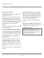
About this User Manual
This User Manual provides installation and operation instructions for the OmniView IP 5000 HQ system produced by Belkin International, Inc.
It is intended for system administrators and network managers, and assumes that readers have general understanding of networks, LDAP,
hardware, and software.
All information in this User Manual is subject to change without prior notice.
1.1 Key features
OmniView IP 5000HQ is a robust central management appliance that
provides reliable and secure management of IP devices.
IT Management - OmniView IP 5000HQ centralizes the management
of all devices, authentication, and global operation from a web browser.
The local administrator can monitor, control, and manage the various
devices, user accounts, and authorization from one web interface.
OmniView IP 5000HQ integrates with Belkin IP devices and serial
console server devices to facilitate an intuitively manageable,
centralized out-of-band access portal—designed to maintain all IT
assets. OmniView IP 5000HQ centralizes all user account information
relevant for IP device administration without interfering in the standalone
survivability of each device.
Automatic Discovery - Belkin IP devices are discovered automatically
by the OmniView IP 5000HQ Manager.
Access Services - Connect to a variety of both hardware and software
external resources such as: ILO, RDP, SSH, VNC, and web pages, etc.,
from the OmniView IP 5000HQ interface.
OmniView IP 5000HQ is Web-based, and is managed using XML over
HTTPS, which allows for secure, yet highly adaptable, administration.
Designed to work across LAN or WAN, OmniView IP 5000HQ monitors
and auto-configures KVM IP devices, whether residing on the local
enterprise network or in remote branches.
Security - OmniView IP 5000HQ provides an extra security layer in
addition to the existing authentication and encryption policy—ensuring
that only authorized users can access servers.
OmniView IP 5000HQ delivers the most advanced solution for enterprise
IT management and remote control. It supports multiple servers in
different locations in an environment that is completely configurable by
the network administrator.
OmniView IP 5000 HQ
Availability - Maximizes uptime by centralizing management and
allowing immediate and effective maintenance.
1
Introduction
Table of Contents
sections
1
2
3
4
5
6
7
8
9
10
11
12
13
14
15
16
17
18
19
20
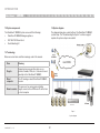
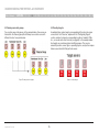
1.2 System components
1.4 System diagram
The OmniView IP 5000HQ system comes with the following:
The diagram below gives a brief outline of the OmniView IP 5000HQ
system setup. The “Understanding the System” section on page 5
explains the system setup in more detail.
•
OmniView IP 5000HQ Manager appliance
•
IEC 10A–125V Power Cord
•
Rack-Mounting Kit
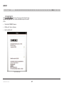
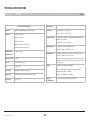
1.3 Terminology
Below are some terms and their meanings used in this manual.
Term
Meaning
Targets
Computers/servers and other devices, e.g.,
printers, firewalls, PDUs, etc., that are accessed
remotely via the OmniView IP 5000HQ
Client
computer
The PC running a remote OmniView IP 5000HQ
session
Remote session
The process of accessing and controlling
targets connected to a KVM-over-IP device from
a client computer
Figure 1
System diagram
OmniView IP 5000 HQ
2
21
Pre-Installation Guidelines
Table of Contents
sections
1
2
3
4
5
6
7
8
9
10
11
12
13
14
15
16
17
18
19
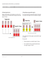
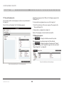
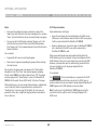
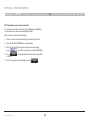
For Windows XP, 2003 Server, Vista, and 2008 Server, deactivate
“Enhanced pointer precision”. To do so:
Appendix A (a separate file on this CD) contains three lists of the details
you need to prepare for Belkin OmniView KVM-over-IP devices, power
distribution units (PDUs), and Serial Console Servers. Photocopy or print
out Appendix A. For other Access Services, see the “Access Services
details” section on the next page.
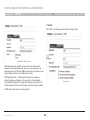
From the “Control Panel” select “Printers and Other Hardware”. Click
the “Mouse” icon. The “Mouse Properties” box appears. See Figure 2.
Select the “Pointer Options” tab.
The lists should include the IP device name and MAC address, KVM
switch, and the target details.
For each target, list:
A unique and clearly identifiable name
•
The operating system
•
Non-default mouse settings. Default mouse settings do not need to
be listed.
Figure 2 Pointer tab
The “Motion” section slider bar must be in the center, and the
“Enhanced pointer precision” check box must be unchecked.
Click “OK” to save changes.
OmniView IP 5000 HQ
21
Note! For Windows® XP, 2003 Server, Vista®, and 2008 Server
Prepare a list of all OmniView IP 5000HQ system components. You will
need this information to configure the system.
•
20
3
Pre-Installation Guidelines
Table of Contents
sections
1
2
3
4
5
6
7
8
9
10
11
12
13
14
15
16
17
18
19
20
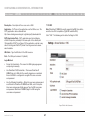
2.1 Access Services details
2.1.1 Adding user-defined Access Services
Besides the Belkin OmniView KVM-over-IP devices mentioned above,
you can connect to targets via the following Access Services through
OmniView IP 5000HQ:
You can also add your own Access Services, explained on page 65.
•
Belkin Serial Console Server
•
Web
•
ILO
•
RDP
•
SSH
•
VNC
•
Telnet
•
VMware Server
These services are elaborated on in the “Access Services” section.
All service applications must be installed on the local (client) computers.
See the “Configuring Access Services” section on page 55, which sets
out the details required for each of the above Access Services.
OmniView IP 5000 HQ
4
21
Understanding the System – An Overview
Table of Contents
sections
1
2
3
4
5
6
7
8
9
10
11
12
13
14
15
16
17
18
19
20
21
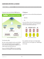
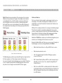
3.1 Creating users
The figure below shows a typical OmniView IP 5000HQ application.
An administrator can create users with two different possible permission
types:
•
Administrator
•
User
A user can be a full user or just view only. These permission types are
explained fully in the “Account policy” section. In the example below,
four users are created with various permission types.
Figure 4 Users with different permissions
Figure 3 OmniView IP 5000HQ typical application
The system works as follows:
Once an administrator creates targets or sets of targets (explained
below) in the system, users can be assigned access to individual targets
or sets of targets.
Data centers in locations throughout the world are connected to Belkin
IP devices and to other third-party Access Services. The Belkin IP
devices are HQ-enabled, allowing the OmniView IP 5000HQ to access/
control the targets connected to all IP devices via IP.
Users access the OmniView IP 5000HQ web interface and, depending
on their level of access permissions, can access and control the targets.
OmniView IP 5000 HQ
5
Understanding the System – An Overview
Table of Contents
sections
1
2
3
4
5
6
7
8
9
10
11
12
13
14
15
16
17
18
19
20
21
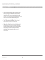
3.2 Forming users into groups
3.3 Creating targets
You can form users into groups. In the example below, three users are
formed into the Finance group. Note! Groups can contain users with
different levels of user permissions.
An administrator creates targets corresponding to the physical servers
connected to the IP devices, explained in the “Configuring Targets”
section, and also to targets corresponding to printers, firewalls, PDUs,
etc., accessed via Access Services (see page 8). In the example below,
four targets are created and given identifying names. They can be
named by location, server type, or operating system, or any other unique
feature associated with that particular server.
Figure 6 Created targets
Figure 5 Forming users into groups
OmniView IP 5000 HQ
6
Understanding the System – An Overview
Table of Contents
sections
1
2
3
4
5
6
7
8
9
10
11
12
13
14
15
16
17
18
19
20
3.4 Forming targets into sets
3.5 Associating a user group with a target set
Targets can be formed into sets. For example, you can create a set of
all financial servers. In the example below, three targets are formed into
target set – Finance.
You can then associate the user group with the target set, thus giving
access rights to all the targets in the set to all members of the group.
Figure 8 User group - target set association
In the example above, the Finance group is associated with the target
set – Finance.
Figure 7 Forming targets into sets
This means that:
OmniView IP 5000 HQ
7
•
The Finance group has access rights to target set – Finance.
•
Any user added to the Finance group will automatically have
access rights to target set – Finance.
21
Understanding the System – An Overview
Table of Contents
sections
1
2
3
4
5
6
7
8
9
Note! Although users are members of the same group, they can have
different access permissions to targets. For example, some could be
users allowing them to control the targets, and some could be view
only, letting them see the server screens, but without being able to
take control. Also, users can be members of many different groups. In
the example below, Sam belongs to the Finance group and also to the
Marketing group.
10
11
12
13
14
15
16
17
18
19
20
21
3.6 Access Services
The Access Services feature supports a wide range of remote access
technologies. This enables the assignment of multiple services to a
single target, so you have the option of in-band or out-of-band access
to the same device.
KVM over IP is a hardware method of accessing and controlling a target.
The other Access Services encompass gaining remote access and
control of a target through the Internet or LAN network via Belkin Serial
Console Server or third-party software. Both hardware and software
methods of access are managed by OmniView IP 5000HQ.
OmniView IP 5000HQ also enables you to effortlessly integrate any new
remote access technology into the remote access portal.
Besides the Belkin KVM-over-IP devices, you can connect to targets via
the following Access Services through OmniView IP 5000HQ:
Figure 9 Same user in different groups
The Marketing group could be associated with targets or target sets that
the Finance group is not. Sam, being a member of both groups,
has access to targets to which both groups are associated. Phil only has
access to targets associated with the Marketing group. Dave and Jon
only have access to targets associated with the Finance group.
OmniView IP 5000 HQ
8
•
Belkin Serial Console Server is a 16-port RS232 device server.
•
Web browser-based web service
•
ILO - HP Integrated Lights-Out (iLO). HP ILO gives seamless
access to HP servers.
•
RDP - Remote Desktop Protocol. RDP is a multi-channel protocol
that allows a user to connect to a computer running Microsoft®
Terminal Services.
•
SSH - Secure Shell. SSH is a network protocol that allows data to
be exchanged using a secure channel between two computers. An
SSH client program is typically used for establishing connections
to an SSH daemon.
Understanding the System – An Overview
Table of Contents
sections
1
2
3
4
5
6
7
•
VNC - Virtual Network Computing. VNC is a graphical desktop
sharing system that uses the RFB protocol. VNC is platformindependent—a VNC viewer on any operating system usually
connects to a VNC server on any other operating system. There are
clients and servers for almost all GUI operating systems.
•
Telnet - TELecommunication NETwork. Telnet is a network
protocol used on the Internet or LAN connections.
•
VMware Server - VMware Server is a free virtualization product
for Windows and Linux® servers with enterprise-class support.
It enables companies to partition a physical server into multiple
virtual machines and to start experiencing the benefits of
virtualization. VMware Server gives seamless access to
virtual machines.
OmniView IP 5000 HQ
8
9
9
10
11
12
13
14
15
16
17
18
19
20
21
Setting Up the System
Table of Contents
sections
1
2
3
4
5
6
7
8
9
10
11
12
13
14
15
16
17
18
19
20
21
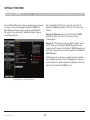
Also in the OmniView IP HQ section in Figure 10, specify how the
OmniView IP 5000HQ server detects the IP device. This can be done
either by:
Set up the Belkin KVM-over-IP systems according to their user manuals’
instructions. In order to be managed by OmniView IP 5000HQ, all
Belkin KVM-over-IP devices must be configured to be OmniView IP
HQ-enabled. This is done from the “Network Configuration” page of
each KVM-over-IP device.
Manager Auto Discovery – When checked, OmniView IP 5000HQ
automatically detects the IP device if it resides on the same
network segment.
Manager IP – If the IP device resides on a different segment, type the
static IP address of the OmniView IP 5000HQ Manager. (We advise
typing the static IP address of the OmniView IP 5000HQ Manager even if
the IP device resides on the same network segment as the OmniView IP
5000HQ Manager.)
Install third-party Access Services according to their own installation
and configuration instructions. See the “Configuring Access Services”
section on page 55 for details required for the integration of the Access
Services into the OmniView IP 5000HQ system.
Figure 10 Enabling HQ for OmniView IP 5XXXG series
OmniView IP 5000 HQ
10
Setting Up the System
Table of Contents
sections
1
2
3
4
5
6
7
8
4.1 Connecting the OmniView IP 5000HQ Manager
10
11
12
13
14
15
16
17
18
19
20
21
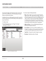
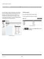
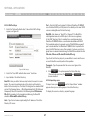
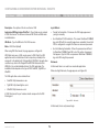
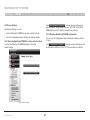
4.2.1 Changing the OmniView IP 5000HQ Manager network parameters
1. Open your web browser (Internet Explorer® version 6.0 or higher).
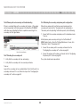
1. Connect the OmniView IP 5000HQ Manager to the network as follows: On the rear panel, connect an Ethernet cable to LAN 1. Connect the other end of the Ethernet cable to the network switch.
2. Type in the IP address of the OmniView IP 5000HQ Manager (default IP
address https://192.168.2.200) and press “Enter”. (Change your
computer network settings, if necessary.) The login page appears.
2. Connect the OmniView IP 5000HQ Manager to a power supply outlet.
3. Type the login name “admin” and password “SMBremote”.
4.2 OmniView IP 5000HQ Manager’s default IP address
4. Navigate to the “Network” tab under “Settings/Unit Maintenance” and
change the network parameters to suit your network configuration.
Each OmniView IP 5000HQ Manager unit comes with the following
default values:
5. Press “Save” and restart the OmniView IP 5000HQ Manager.
IP address - 192.168.2.200
6. Wait for the system to restart and log in with the new IP address.
Subnet mask - 255.255.255.0
Gateway - 192.168.2.1
If these values are not suitable for your network, follow the steps in the
section below to display the OmniView IP 5000HQ interface. You can
then change the IP address of the OmniView IP 5000HQ Manager in the
“Network” tab under “Settings/Unit Maintenance”; see the “Network tab”
section on page 95.
OmniView IP 5000 HQ
9
11
Displaying the OmniView IP 5000HQ Web Interface
Table of Contents
sections
1
2
3
4
5
6
7
8
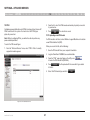
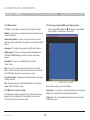
To display the web interface:
9
10
11
12
13
14
15
16
17
18
19
21
2. Type in the IP address of the OmniView IP 5000HQ Manager
(default IP address https://192.168.2.200) and press “Enter”.
1. Open your web browser (Internet Explorer version 6.0 or higher).
Note! The IP address must begin with https:// and not http://. The login
page appears. Bookmark it for easy reference.
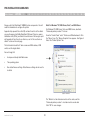
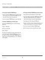
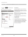
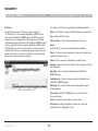
Windows Vista Note! To log in to the web configuration interface with
Windows Vista, run Internet Explorer as Administrator. To do this,
right-click the Internet Explorer icon and select “Run as administrator”.
See figure below.
3. Type the login name and password. Default user name is “admin”
and password is “SMBremote”.
4. Press “Enter”. The web interface appears; see Figure 12.
Figure 12 Devices page
Figure 11 Running IE in Vista
OmniView IP 5000 HQ
20
12
Displaying the OmniView IP 5000HQ Web Interface
Table of Contents
sections
1
2
3
4
5
6
7
8
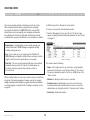
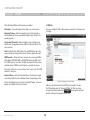
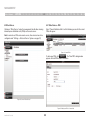
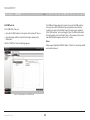
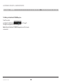
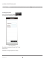
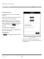
Note! On the first connection, the OmniView IP 5000HQ GUI prompts you
to install the OmniView IP 5000HQ client software; see Figure 13.
Click “Install”.
9
10
11
12
13
14
15
16
17
18
19
20
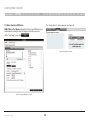
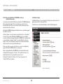
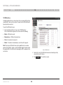
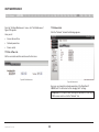
5.1 Menu section
The menu section is on the left; see that Figure 12 is sub-divided into
three sections:
Management, which includes the configuration pages for IP devices,
targets, and users/groups.
Access, which contains access pages to all allowed targets and
target groups.
Settings, which contains two configuration sections: Application
and Maintenance.
This guide explains the menu sections from the point of view of first
setting up the system and then operating it.
The guide explains in the following order how to:
Figure 13 ActiveX control installation
OmniView IP 5000 HQ
13
•
Create Users
•
Configure Targets
•
Configure Devices
•
Configure Settings
•
Configure Access Services
•
Access the System
•
Configure Advanced Settings
21
Creating Users
Table of Contents
sections
1
2
3
4
5
6
7
8
There are two possible methods of inputting users into the system.
When using local authentication (see page 44), users and groups
are created in the OmniView IP 5000HQ GUI. When using an LDAP
authentication server (see page 46), users and groups are imported
from a Windows Active Directory. With both authentication methods,
an administrator can grant users different access permissions as follows:
9
10
11
12
13
14
15
16
17
18
19
20
21
In LDAP mode, go to the “General tab” section below.
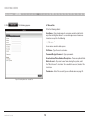
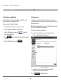
To create a new user (in local authentication mode):
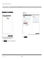
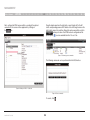
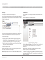
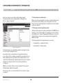
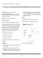
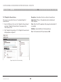
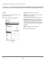
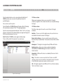
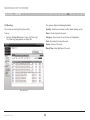
1. From the “Management” menu, select “Users”. The “Users” page
appears showing the default administrator (admin) at the top of the list;
see Figure 14.
Administrator – An administrator can view, modify, manage, and
control all OmniView IP 5000HQ Manager configuration settings,
including creating new users.
User – A user cannot access or change any of the OmniView IP
5000HQ Manager configuration settings. When a user logs in, only the
targets to which the user has permission to access appear.
Figure 14 Users page
View Only – This user can only view permitted target screens without
keyboard and mouse control. A “view only” indicator appears on
the viewer’s local mouse pointer. View only has no effect on
Access Services.
The columns show the following:
•
With local authentication, once you have created users you can form them
into groups. This makes management changes easier by, for example,
adding or deleting permitted targets per group rather than per individual
user. Creating groups is explained in the “Creating a user group” section
on page 19.
Name – User’s login name. You can search for a user by typing the
login name in the “Search a user” field and clicking . You can sort the names in alphabetical order A–Z or Z–A by clicking the top of the
“Name” column.
• Member of – Groups in which the user is a member.
• Permission Level – Administrator or user. You can sort the users
in permission-level order—administrators then users, or users then
administrators—by clicking the top of the “Permission Level” column.
• Description – Optional description.
OmniView IP 5000 HQ
14
Creating Users
Table of Contents
2. Click
sections
1
2
3
4
5
6
7
8
9
10
11
12
13
14
15
16
17
18
19
20
21
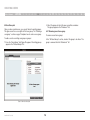
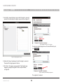
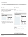
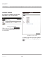
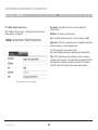
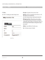
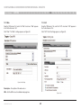
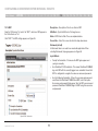
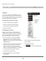
6.1 General tab
. The following appears.
Fill in the following details:
User Name – Type a login name. A user name cannot be identical to
any other existing User name. It can contain uppercase or lowercase
characters except for the following:
: ; ? & < > ”
A user name cannot include spaces.
Full Name – Type the user’s real name
Password/Retype Password – Type a password.
E-mail address/Phone Number/Description – These are optional fields.
Block Account – To prevent a user from entering the system, select
the “Block Account” check box. To re-enable the account, deselect the
check box.
Permission – Select the account type as outlined above on page 14.
Figure 15 Creating a New User – General Tab
OmniView IP 5000 HQ
15
Creating Users
Table of Contents
sections
1
2
3
4
5
6
7
8
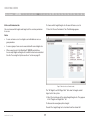
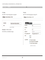
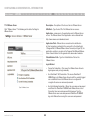
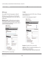
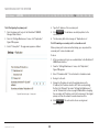
6.2 User Group tab
10
11
12
13
14
15
16
17
18
19
20
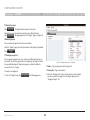
2. Select the groups of which the new user will be a member.
The groups appear in the “Member of” list.
Once you have created users, you can put them into existing groups.
This gives users the access rights of that user group. The “Creating a
user group” section on page 19 explains how to create a user group.
6.2.1 Removing users from a group
To remove users from a group:
To add a user to an existing user group or groups:
In the “All User Groups” section, deselect the group’s check box. The
group is removed from the “Member of” list.
1. Press the “Users Group” tab; Figure 16 appears. All existing groups appear in the “All User Groups” list.
Figure 16 New User Group tab
OmniView IP 5000 HQ
9
16
21
Creating Users
Table of Contents
sections
1
2
3
4
5
6
7
8
9
10
11
12
13
14
15
16
17
18
19
20
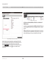
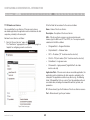
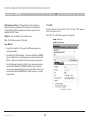
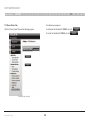
6.3 Access Permissions tab
To choose which targets/target sets the user will have access to:
You can choose which targets and target sets the user has permission
to access.
1. Press the “Access Permissions” tab. The following appears.
21
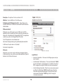
Notes:
•
A user can have access to a target as an individual user or as a group member.
•
A user or group of users can be associated with several target sets.
•
When a user logs in to the OmniView IP 5000HQ web interface,
he sees only targets and target sets to which he has been associated.
See the “Accessing the System as a User” section on page 81.
Figure 17 New User Access Permissions tab
The “All Targets” and “All Target Sets” lists show the targets and all
target sets in the system.
2. Select the check boxes of the desired targets/target sets. They appear
in the “Targets and Target Sets:” list.
To disassociate a user/group from a target:
Deselect the targets/target sets check box from the relevant list.
OmniView IP 5000 HQ
17
Creating Users
Table of Contents
sections
1
2
3
4
5
6
7
8
6.4 Saving a user
Click 9
10
11
12
13
14
15
16
17
18
19
21
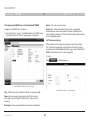
6.4.1 Deleting a user
. The user’s details are now in the system.
Deleting a user instantly removes the user’s authorization from the
OmniView IP 5000HQ system and all IP devices.
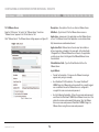
Repeat this process to add more users. When finished, click .
All users appear on the “Users” page. The number of users appears in
brackets after “Users” in the menu; see Figure 18. User groups appear
as a sub-folder in the menu. Creating user groups is explained below.
To delete a user:
1. On the “Users” page select the check boxes of the users to be deleted.
2. Select or deselect all check boxes with one click.
Figure 19 Deleting a user
Figure 18 List of users in the system
Click By clicking a user name, an administrator can access the “General”,
“User Group”, and “Access Permissions” tabs of this user and change
any of the parameters.
OmniView IP 5000 HQ
20
18
. The user’s details are now in the system.
Creating Users
Table of Contents
sections
1
2
3
4
5
6
7
8
9
10
11
12
13
14
15
16
17
18
19
20
21
6.5 Creating a user group
2. Name: Type a unique name for the group. You can add a description.
Once you have created users, you can form them into groups. You then
give the same access permissions to the entire group without having to
go through the process for each individual user.
3. Select the check boxes of the users to be part of the group. They appear in the “Group members” list.
You can access the “User Properties” page by clicking a user name in
the “Group members” list.
To create a user group:
1. From the menu, click “Users” or “User Groups”. On either of these pages,
click . The “New User Group” page appears; see Figure 20.
Figure 20 Creating a New User Group – Members tab
OmniView IP 5000 HQ
19
Creating Users
Table of Contents
sections
1
2
3
4
5
6
7
8
9
10
11
12
13
14
15
16
17
18
6.5.1 Access Permissions tab
6.5.2 Allowed Services tab
Click the “Access Permissions” tab; Figure 20 appears.
Click the “Allowed Services” tab. The following appears.
Figure 21 Creating New Users – Access Permissions tab
19
20
21
Figure 22 Creating a New User Group – Allowed Services tab
From the “All Targets” and “All Target Sets” lists, select the check
boxes of those to which the new user group will have permission to
access. When selected, the target/set appears in the “Targets and
Target Sets” list.
Here you can assign Access Services to group members. If a group
member has permission to access a target, but there are no assigned
Access Services for the group, then the group member will not be able
to access the target.
To remove targets/sets, deselect the check boxes.
Select the check boxes of all Access Services allowed to this group.
OmniView IP 5000 HQ
20
Creating Users
Table of Contents
sections
1
2
3
4
5
6
7
8
9
10
11
12
13
6.5.3 Saving the new group
6.5.4 Deleting a user group
Click
To delete a group:
. The group’s details are now in the system.
Repeat this process to add more groups. When finished,
click . All groups appear on the “User Groups” page;
see Figure 23.
14
15
16
17
18
19
1. On the “Users Group” page, select the check boxes of the groups to
be deleted.
Tip! The allowed services appear as icons. To see which service the
icon represents, hold the mouse over the icon and a tool tip appears
with the name of the service.
You can create different access profiles. You can give permission
to targets and define different access rights through the
“Allowed Services”.
Figure 24 Deleting a user group
2. Press
. The groups are removed.
Note: Deleting a group will not delete the individual users.
Figure 23 User Groups page
OmniView IP 5000 HQ
20
21
21
Configuring Targets
Table of Contents
sections
1
2
3
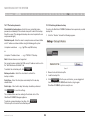
4
5
6
7
8
9
10
11
12
13
14
15
16
17
18
19
20
21
The columns display the following information:
You must input the details of all the targets physically connected to the
system’s IP devices/KVM switches. This includes giving each target a
unique name and other relevant details.
To configure a target:
•
Name – Name of target. You can search for a target by typing the
target name in the “Find a Target” field and clicking . You can sort
the names in alphabetical order A–Z or Z–A by clicking the top of the
“Name” column. You can also select which targets to display from
the “Show by Service” drop-down list. You can show all targets or
just show targets with a particular Access Service; to do so, choose
the desired service from the “Show by Service” drop-down list.
1. From the “Management” menu, select “Targets”. The “Targets”
page appears; see Figure 25.
•
KVM over IP Device – The type of Belkin OmniView KVM-over-IP
device to which the target is connected.
•
Access Services – Icons of Access Services available to access
the target. To see which service the icon represents, hold the mouse
over the icon and a tool tip appears with the name of the service.
•
Target Sets – The target sets to which this target is a member.
•
Description – Optional description of the target.
As mentioned in the pre-installation guidelines, Appendix A (separate file
on this CD) contains three lists of all the details you need to prepare (you
may not need all three).
Figure 25 List of existing targets in the system
OmniView IP 5000 HQ
22
Configuring Targets
Table of Contents
sections
2. From the toolbar, click
see Figure 26.
1
2
3
4
5
6
7
8
9
10
11
12
13
14
15
16
17
18
19
20
21
7.1 Access Services tab
. The “New Target” page appears;
Here you select and configure all Access Services relevant to this target.
Name – Type a unique name for each server in the system.
All Services/Active Services: From the “All Services” list, select the check
box of all Access Services relevant to this target. Once selected, the service
appears in the “Active Services” list.
Note! Below discusses how to configure Belkin IP devices. Configuring
other Access Services is discussed in the “Configuring Access Services for
Individual Targets” section on page 67.
The pre-installation guidelines on page 3 explained what information you
need to configure each target.
7.1.1 Default Access Service
You can set any of the Access Services to be the default service. This
means that the service will be used to access the target by default when
selecting the target by clicking its name. To access the target via a different
service, the service must be selected. To set a service as the default,
display the service as explained below and select the “Set as Default
Service” check box, circled in Figure 26.
Figure 26 Creating a New Target – Access Services tab
OmniView IP 5000 HQ
23
Configuring Targets
Table of Contents
sections
1
2
3
4
5
6
7
8
7.1.2 Belkin OmniView KVM Switch
9
10
11
12
13
14
15
16
17
The “Assign Device” window appears; see Figure 28.
KVM/IP Device/Port Number: Assign the IP device and KVM switch port
number (where relevant) to which this target is physically connected.
On the “New Target” page, click .
Figure 28 Assign Device window
Figure 27 Assigning KVM port to a target
OmniView IP 5000 HQ
18
24
19
20
21
Configuring Targets
Table of Contents
sections
1
2
3
4
5
6
7
8
9
10
11
12
13
14
15
16
17
18
19
3. From the list, expand the device type to which the target is connected
and select the actual device the target is connected to; see Figure 29.
Figure 30 KVM-over-IP Device / Port number
To remove an assigned target from an IP device/KVM switch port,
click .
Figure 29 Assigning targets to devices
4. Double-click the port number row to which the target is connected.
The name of the target appears in that row.
5. Click “Save”. The changes are saved and the “New Target” page
reappears, showing the assigned IP device and port number;
see Figure 30.
Figure 31 Removing current KVM port assignment
The assignment is removed.
OmniView IP 5000 HQ
25
20
21
Configuring Targets
Table of Contents
sections
1
2
3
4
5
6
7
8
9
10
11
12
13
14
15
16
17
18
19
20
21
Other OmniView KVM-over-IP elements are as follows:
7.2 PDU tab
Description – Type a description for the target, e.g., backup server.
Here you configure IP PDU to allow power on, power off, or to power-cycle
the target.
Operating System – Select the operating system of the target from
the drop-down list. The mouse parameter options adjust to match the
operating system.
Acceleration/Threshold – When the target’s mouse settings are not
default, select the appropriate values. Match the values to those of the
server’s mouse.
Note! For Windows XP, 2003 Server, Vista, and 2008 Server, go to the
mouse settings on the target and uncheck “Enhance pointer precision”.
USB Converter – When an IP device connects to a server via a USB-toPS/2 adapter, ROC/RICC USB, or X RICC USB or Specter USB, select
the “USB Converter” check box. The USB conversion affects the mouse
emulation and the “USB Converter” helps to synchronize the mouse.
Also, when an IP device is connected to a Linux® server, select the “USB
Converter” check box.
Absolute Mouse – Select the “Absolute Mouse” check box for a target
connected to USB, which has a Windows Me or later operating system.
Figure 32 Assigning power outlet to target
See the “Configuring Access Services for Individual Targets” section on
page 67 to configure other Access Services.
OmniView IP 5000 HQ
Make the selection from the list of all PDUs on the right of the box.
The PDU will appear in the “Connected PDUs” list. Next, you have
to assign the outlet number. Click and assign the outlet by
double-clicking on the appropriate outlet row.
26
Configuring Targets
Table of Contents
sections
1
2
3
4
5
6
7
8
9
10
11
12
13
14
15
16
17
18
Figure 34 Current power-outlet selection
Click
Figure 33 Power outlet to target selection
Click
OmniView IP 5000 HQ
and the outlet number will appear.
27
.
19
20
21
Configuring Targets
Table of Contents
sections
1
2
3
4
5
6
7
8
9
10
11
12
13
14
15
16
17
18
19
20
7.3 Target Sets tab
7.4 Access Permissions tab
Creating target sets is explained in the “Creating a target set” section on
page 29. Once you have created target sets, you can put targets into target
sets, giving access rights to all targets in a set to all members.
You can choose which users and groups can have access permission to
the target.
Press the “Access Permissions” tab. The following appears.
1. Press the “Target Sets” tab. The following appears.
Figure 35 Current Target Sets tab
2.From the “All Target Sets” list, select the check boxes of the target sets to which you want the target to be associated. The target set appears
in the “Is a Member of” list.
Figure 36 Current Access Permissions tab
All existing users appear in the “All Users” list. All groups appear in the
“All Groups” list.
To choose which users/groups have access to the target:
1.Select the check boxes of the users or groups. They appear in the “Users and Groups:” list.
To disassociate a user/group from a target:
Deselect the user/group check box from the relevant list.
OmniView IP 5000 HQ
28
21
Configuring Targets
sections
Table of Contents
1
2
3
4
5
6
7
8
9
10
11
12
13
14
15
16
17
18
19
20
7.5 Saving the target
Click . The target details are now in the system.
Repeat this process to input all connected servers. When finished,
click
. All targets appear on the “Targets” page; see Figure 25.
7.6 Deleting targets
You can remove targets from the system as follows:
From the “Targets” page, select the check boxes of the targets to be deleted.
Press .
7.7 Creating a target set
You can group targets into sets, e.g., make a set of all financial servers in
the system. You can then give users access rights per the target set rather
than per individual targets. Target sets appear as a Favorites folder for
users on the “Access” page.
2.Name – Type a unique name for the target set.
To create a new target set:
3.Description – Type a description.
1. From the “Targets” page, click OmniView IP 5000 HQ
Figure 37 Creating New Target Set – Targets tab
4.From the “All Targets” list, select the check boxes of the targets you want to add to the target set. The targets appear in the
“Assigned Targets” list.
. The following appears.
29
21
Configuring Targets
Table of Contents
sections
1
2
3
4
5
6
7
8
7.7.1 Access Permissions tab
9
10
11
12
13
14
15
16
17
18
19
20
All existing users appear in the “All Users” list. All groups appear in the
“All Groups” list.
You can choose which users and groups can have access permissions to
the target set.
To choose which users/groups have access to the target set:
Press the “Access Permissions” tab. The following appears.
1. Select the check boxes of the users or groups. They appear in the
“Users and Groups:” list.
To disassociate a user/group from a target set:
Deselect the user/group check box from the relevant list.
7.7.2 Saving the target set
Click . The target set details are now in the system.
Repeat this process to add more target sets. When finished,
click . All target sets appear in the menu under “Targets/
Target Sets” and also on the “Target Sets” page. From the menu, select
“Targets/Target Sets”; see Figure 39.
Figure 39 Current Target sets in the system page
Figure 38 Creating New Target Sets – Access Permissions tab
OmniView IP 5000 HQ
30
21
Configuring Targets
Table of Contents
sections
1
2
3
4
5
6
7
8
9
10
11
12
13
14
15
16
17
18
19
20
21
7.7.3 Deleting a target set
To see all the targets in a target set, click the target set name either from
the menu or on the page; see Figure 40. From this page you can at any
time assign or remove targets from the target set. From the “Access
Permissions” tab, you can choose which users and groups can have
access permissions to the target set. You can access target properties by
clicking a target name in the “Assigned Targets” list.
You can delete a target set from the “Target Sets” page:
1. Select the check boxes of the target set to be deleted.
Figure 41 Deleting a target set
2.Press . The target set is removed. Note: Deleting a target set
will not delete the individual targets.
Figure 40 Editing a target set
OmniView IP 5000 HQ
31
Management
Table of Contents
sections
1
2
3
4
5
6
7
8
9
10
11
12
13
14
15
16
17
18
19
20
21
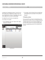
8.1 Devices
The columns on the “Devices” page display the following information:
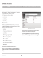
The web interface opens at the “Devices” page; see Figure 42.
The “New Devices” section automatically displays all KVM IP devices
detected by the OmniView IP 5000HQ system. (For KVM IP devices to
appear, they must be configured to be HQ enabled—see the “Setting
each OmniView KVM-over-IP Switch to be OmniView IP 5000HQ enabled”
section on page 36.) Each device appears identified by its MAC address.
The MAC address of each IP device is written on a sticker on the unit’s
underside. Once the device is configured by giving it a name, it then only
appears in the “Devices” section. The “New Devices” section itself only
appears when there are new devices detected.
Name – Once IP devices are given an identifying name, they appear here.
Type – Connected IP device type.
Connected User – User currently operating the remote session.
Status
Under the “Status” column, there are the following possibilities:
Online – The device is up and running and is ready to be configured, or is
available for a remote session.
Alarm – Device is down and is unavailable for a remote session.
Warning – Problem with the device. See the “Devices” page on the left for
more information.
Uploading – Device is receiving new firmware from OmniView IP
5000HQ Manager.
Updating device – Device is receiving an updated configuration from
OmniView IP 5000HQ Manager.
Rebooting – Device reboots upon any network parameter change or
firmware upgrade.
Figure 42 Current KVM Devices page
Connecting – OmniView IP 5000HQ sends or receives the Device
Discovery message.
Version – Displays the device firmware version number.
Description – Identifying description of the device as input by the
administrator when configuring the device.
OmniView IP 5000 HQ
32
Management
Table of Contents
sections
1
2
3
4
5
6
7
8
9
10
11
12
13
14
15
16
17
18
19
20
21
8.2 Other Devices
8.2.1 Other Devices – PDU
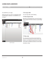
Clicking on “Other Devices” under the management tab will allow choosing
between power distribution units (PDUs) and console servers.
Select “Power Distribution Units” and the following screen with the current
PDUs will appear.
Note: In order to use PDUs and console servers, these devices have to be
configured under “Settings — Attached Devices” (please see page 51).
Figure 44 Current PDUs
To add a new PDU, click . The “New PDU” dialog window
appears. Enter all PDU-related information.
Figure 43 Current “Other Devices”
Figure 45 Adding new PDUs – General tab
OmniView IP 5000 HQ
33
Management
Table of Contents
sections
1
2
3
4
5
6
7
8
Next, configure the PDU’s power outlets according to the physical
connection to the server or other equipment by clicking on
the tab.
9
10
11
12
13
14
15
16
17
18
19
21
Drag the target name from the right side’s current targets list to the left
side’s corresponding power outlet. Double-click on the target name on the
right side to remove the selection. Repeat for each power outlet, and click when you’re done. Your PDU has been configured and the
power option ( ) becomes available from the “Access” tab.
Figure 47 Performing power commands
The following commands can be performed from the HQ interface.
Figure 46 Adding new PDUs – Outlets tab
Figure 48 Power commands
To cancel, click
OmniView IP 5000 HQ
20
34
.
Management
Table of Contents
sections
1
2
3
4
5
6
7
8
9
10
11
12
13
14
15
16
17
18
19
20
21
8.2.2 Other Devices – Console Server
Select “Console Server” from “Management > Other Devices” and the
following screen with the current console servers will appear.
Figure 49 Current console servers in the system
To add a new console server to the setup, click .
The “New Console Server” dialog window appears. Enter all console
server-related information.
Figure 50 Adding new console servers – General tab
Next configure the console server’s serial connections according to the
physical connection to the server or other equipment by clicking on the tab.
OmniView IP 5000 HQ
35
Management
Table of Contents
sections
1
2
3
4
5
6
7
8
9
10
11
12
13
14
15
16
17
18
19
20
21
Figure 52 Using console servers
8.3 Setting each OmniView KVM-over-IP Switch to be OmniView IP
5000HQ-enabled
In order to be managed by OmniView IP 5000HQ, all Belkin KVM IP devices
must be configured to be HQ. See the “Setting Up the System” section on
page 10.
Tip! Since KVM IP devices only appear in the “New Devices” list once they
are HQ-enabled, make each KVM IP device HQ-enabled in a certain order
with a suitable time gap, so that you can identify the unit’s location.
Figure 51 Adding new console servers – Serial tab
Drag the target name from the right side’s current targets list to the left
side’s corresponding serial port. Double-click on the target name on the
right side to remove the selection. Repeat for each power outlet,
and click when you’re done. Your console server has been
configured and the console server ( ) becomes available from the
“Access” tab.
OmniView IP 5000 HQ
36
Management
Table of Contents
sections
1
2
3
4
5
6
7
8
9
10
11
12
13
14
15
16
17
18
19
20
21
8.4 Configuring the KVM IP devices in the OmniView IP 5000HQ
Status – This is the connection status.
Configure a new KVM IP device as follows:
Device Info – Contains information about the device, including its
operational status and version numbers of firmware, KME (keyboard,
mouse emulation), hardware, SDF (switch definition file), and date and time
of last configuration update.
1. In the “New Devices” section, click the MAC address of a KVM IP device. The “General” tab of the “Devices” page appears; see Figure 53.
8.4.1 The Advanced button
When required, you can change the performance and mouse settings
(the “Set mouse and performance from KVM over IP Session” must be
unchecked on the “Settings/Global Settings” page—see the “OmniView IP
5000HQ session idle time-out” section on page 50).
To do so:
Press . The following appears:
Figure 53 KVM-over-IP Devices page – General tab
Figure 54 KVM-over-IP device – Advanced page
Type – KVM IP device type, OmniView IP 5232K, etc. (read-only field).
Name –You must assign a unique name to each IP device before
associating connected targets or KVM switches. Type a name for
the device.
Description – These are optional fields used for device identification.
OmniView IP 5000 HQ
37
Management
Table of Contents
sections
1
2
3
4
5
6
7
8
9
10
11
12
13
14
15
16
17
18
19
20
21
8.4.2 Performance
8.4.3 Mouse
Bandwidth has the following options from the drop-down menu:
Select the appropriate values according to the type of mouse connected to
the device.
High
Type – Select the mouse type you would like the IP device to emulate.
When setting the mouse emulation type, set it to match the mouse
connected to the local console port on the IP device, e.g., if the local mouse
is a 2-button mouse, but not from Microsoft, set the mouse-emulation type
to “Standard Mouse” and uncheck the “Microsoft” check box.
For optimal performance while working with a local area (LAN) connection,
select “High” bandwidth. This will adjust the performance to low
compression and high color (16-bit).
Low
Tip! The mouse on most KVM drawers in a standard rack is a standard
mouse.
For optimal performance when using a dial-up connection, select “Low”
bandwidth. This will adjust the performance to high compression and 16
colors. For improved performance, verify that the “Color” selection is a
16-color palette.
Microsoft – Uncheck this box if the mouse does not work using Microsoft
mouse protocol.
Medium
Important!!
When working on DSL, cable, or ISDN connections, select “Medium”.
We recommend not changing the Advanced settings unless
there is erratic mouse behavior. For example, the mouse makes
random clicks and jumps arbitrarily around the screen.
Custom
Custom gives you the option to manually choose both the compression
and colors.
OmniView IP 5000 HQ
Press “Apply” to save changes and return to the
“Device Properties” page.
38
Management
sections
Table of Contents
1
2
3
4
5
6
7
8
8.5 KVM Ports tab
10
11
12
13
14
15
16
17
18
19
20
21
The KVM switch drop-down list consists of pre-selected KVM switches.
You must select all the KVM switch types physically connected to the
system; this is done in the “Settings” part of the menu and is explained
in the “KVM switches” section on page 52. Select the KVM switch model
(if any) physically connected to this IP device. The number of ports in the
selected KVM switch appears in the “Ports” section.
In the “KVM Ports” tab, you:
• Associate the KVM switches in the system to the relevant IP device.
• Associate targets with the relevant IP device/port number on the
KVM switch.
Notes:
Click the “KVM Ports” tab, the following appears.
When using an OmniView 5216/32K Switch, “Internal” is selected by default
and cannot be altered.
Figure 55 Configuring KVM over IP – KVM Ports tab
OmniView IP 5000 HQ
9
39
Management
Table of Contents
sections
1
2
3
4
5
6
7
8
9
10
11
12
13
14
15
16
17
18
19
20
21
8.6 Targets
8.7 Network tab
The targets you created appear in the “Targets” list.
In the “Network” tab, you configure and modify network parameters of the
IP device.
You can choose to display all targets or just unassigned targets (default), or
targets belonging to a target set. Select the desired option from the “Show
Targets” drop-down menu.
Click the “Network” tab. The following appears.
You must associate the targets with the relevant IP device or with the port
numbers on the KVM switch to which they are physically connected.
To associate the targets:
1. From the “Targets” list, double-click the target connected to port #1 of the KVM switch. The target assigns to port #1 of the “Ports” section. Alternatively, drag and drop the target to the correct port number.
Figure 56 KVM-over-IP Device – Network tab
2.Repeat the above step for all targets connected. Ensure the right target assigns to the correctly numbered port.
To remove a target from a port:
Interface I displays the IP address of the KVM-over-IP device as discovered
by the OmniView IP 5000HQ Manager system. You can change this
address here.
Double-click the target in the “Ports” section. The target name moves to
the “Target” section and is now unassigned.
Enter IP address, subnet mask, and default gateway for the network
adapter, as given by your network administrator.
Note! Deleting a target removes its association with the KVM port number.
In “TCP Ports”, type three ports (from 800 and up to 65535). By default the
port numbers are 900, 901, and 902. These default ports are suitable for the
majority of installations.
OmniView IP 5000 HQ
40
Management
Table of Contents
sections
1
2
3
4
5
6
7
8
9
10
11
12
13
14
15
16
17
18
19
20
Click to clear or select the following according to your requirements:
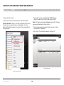
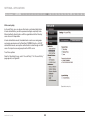
8.10 Device discovery
DHCP – Enable DHCP to provide you with dynamic IP addressing for the IP
device, if a DHCP server exists.
The status of the KVM IP devices is updated automatically every minute.
You can manually discover new devices at any time from the
“Devices” page.
Note: Any change in the network configuration forces the IP device
to restart.
To do so:
8.8 Saving the KVM-over-IP device configuration changes
In the menu, right-click “Devices” and the “Discovery” menu appears;
see Figure 57. Click “Discover Now”. The OmniView IP 5000HQ Manager
performs a device discovery on the network segment. All newly discovered
devices appear in the “New Devices” section.
Press “Save” to save the settings and configure the IP device. The KVMover-IP device is upgraded to the device firmware stored in the OmniView
IP 5000HQ system. It receives the SDF from the OmniView IP 5000HQ
system and also a list of targets, users, and their permissions (CFG). The
KVM-over-IP device may be unavailable during the upgrade and while
receiving the CFG and SDF updates.
8.9 Deleting KVM-over-IP devices
IP devices can be deleted from the OmniView IP 5000HQ system from the
“Devices” page.
Figure 57 Devices page – New Devices discovery
To delete IP devices:
1. From the “Management” menu, click “Devices” and the “Devices”
page appears.
2.Select the check boxes of the units to be deleted, or select the top
check box to select or deselect all check boxes.
3.Click . The devices are deleted.
4.Uncheck “Enable HQ” on the device’s “Network Configuration”
web page. This will prevent the deleted KVM IP device from
being rediscovered.
OmniView IP 5000 HQ
21
41
Settings – Applications
Table of Contents
sections
1
2
3
4
5
6
7
8
9
10
11
12
13
14
15
16
17
18
19
20
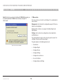
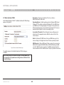
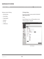
From the menu, click “Settings”. The settings are split into “Applications”,
“Attached Devices”, and “Maintenance” sections.
In the “Applications” section, you configure:
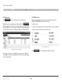
• Access Services
• Account Policy
• Global Settings
9.1 Access Services
Besides connecting to Belkin OmniView IP devices, you can connect
to a variety of both hardware and software external resources from the
OmniView IP 5000HQ interface as follows:
Figure 58 Settings – Access Services
• Web Service
Outlined below are the default template values for Belkin IP devices.
If these values are not suitable, you can change them.
• IP-Enabled Power Distribution Units
• Console Servers
For the default template values of the other factory-included Access
Services, see the “Configuring Access Services” section on page 55.
• ILO - HP Integrated Lights-Out (iLO)
• RDP - Remote Desktop Protocol
• SSH - Secure Shell
• VNC- Virtual Network Computing
• Telnet- TELecommunication NETwork
• VMware Server
See pages 57-64 for an elaboration of the above services.
From the “Access Services” page you can configure Access Services
for targets in the system. You can also add new Access Services from
this page.
OmniView IP 5000 HQ
42
21
Settings – Applications
Table of Contents
sections
1
2
3
4
5
6
7
8
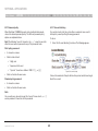
9.1.1 Belkin OmniView IP KVM
9
10
11
12
13
14
15
16
17
18
19
20
21
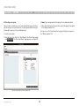
Description – This is the description of the Access Service Belkin OmniView IP KVM device.
Click “Belkin OmniView IP KVM”. The Belkin OmniView IP KVM settings
appear; see Figure 59.
Operating System – Default operating system is Windows 2003 Server/
Windows XP. This setting is suitable for Windows XP, Vista, 2003 Server,
and 2008 Server. If the large majority of the targets in the system have a
different operating system, select it from the drop-down list. The mouse
parameter options adjust to match the operating system.
Acceleration/Threshold – When the target’s mouse settings are not
default, select the appropriate values. Match the values to that of the
server’s mouse.
Note! For Windows XP, 2003 Server, Vista, and 2008 Server, go to the
mouse settings on the target and uncheck “Enhance pointer precision”.
USB Converter – When a KVM-over-IP device connects to a server via a
USB-to-PS/2 adapter, RICC/ROC USB, or X RICC USB or Specter USB,
select the “USB Converter” check box. The USB conversion affects the
mouse emulation and the “USB Converter” helps to synchronize the mouse.
Figure 59 Belkin OmniView IP KVM settings
The default elements of the Belkin OmniView IP KVM settings are
as follows:
Note! Only change the default settings if the large majority of
the targets in the system have settings that are different to the default settings.
OmniView IP 5000 HQ
43
Settings – Applications
Table of Contents
sections
1
2
3
4
5
6
7
8
9
10
11
12
13
14
15
16
17
9.2 Account policy
In Account Policy, you can choose either local or external authentication.
In local authentication, you define password and login complexity levels.
External authentication interfaces with the organizational Active Directory
server for user list importation.
In local authentication mode, the administrator creates users and groups
and assigns permissions via the OmniView IP 5000HQ interface. In LDAP
authentication mode, server option authentication is done through an LDAP
server. You import users and groups from the LDAP server.
To set these options:
From the “Application” menu, select “Account Policy”. The “Account Policy”
page appears; see Figure 60.
Figure 60 Account policy
OmniView IP 5000 HQ
44
18
19
20
21
Settings – Applications
Table of Contents
sections
1
2
3
4
5
6
7
8
9
10
11
12
13
14
15
16
17
18
19
20
9.2.1 Password policy
9.2.1.1 Account blocking
When OmniView IP 5000HQ operates in local authentication mode,
choose the desired password policy. The different password policy
options are explained below.
You can block entry into the system after a number of unsuccessful
attempts by a user inputting the wrong password.
21
To do so:
Note! The following “special” characters: &, <, >, ”, cannot be used for
either the user name or password in any of the password levels.
1. Select the “Account blocking” check box. The following appears.
Strict policy password:
•
8 characters or more
•
Must include at least:
• 1 digit, and
• 1 uppercase letter, and
• 1 “special” character as follows: !.@#$%^ *( )_-+= [ ]{ }
•
Figure 61 Account blocking
Must not include the user name
Choose the number of attempts within a time period and for how long to
block the account.
Standard policy password:
•
6 characters or more
•
Must not include the user name
Note:
You can write any character (except the “special” characters: &, <, >, ”)
and any number of characters for the password.
OmniView IP 5000 HQ
45
Settings – Applications
Table of Contents
sections
1
2
3
4
5
6
7
8
9.2.2 External authentication (LDAP)
10
11
12
13
14
15
16
17
18
19
20
21
Since the OmniView IP 5000HQ user accounts are kept in the local
database, some of the local accounts might not have related LDAP
objects (e.g., some users’ accounts might migrate to another LDAP
path). To clean the local database from those ghost accounts that will
never pass LDAP authentication, OmniView IP 5000HQ provides the
customers with the manual synchronize operation.
LDAP (Lightweight Directory Access Protocol) is a standard protocol for
accessing information in a directory.
LDAP defines processes by which a client can connect to an X.500compliant or LDAP-compliant directory service to add, delete, modify,
or search for information, provided the client has sufficient access rights
to the directory. For example, a user could use an LDAP client to query
a directory server on the network for information about specific users,
computers, departments, or any other information stored in
the directory.
User groups will not be deleted and will be managed locally after
its import.
When changing OmniView IP 5000HQ to local authentication mode, all
the users appear as “inactive.” To reactivate the users, the administrator
must explicitly provide each account with a local password.
Note! OmniView IP 5000HQ supports Windows 2003 and Windows 2008
Active Directory LDAP Authentication.
9.2.2.2 DNS setting in LDAP mode
9.2.2.1 OmniView IP 5000HQ in external authentication (LDAP) mode
In external authentication (LDAP) mode, OmniView IP 5000HQ deletes all
users created before in local authentication mode. New users can only
be imported from a Windows 2003 or Windows 2008 Active Directory.
OmniView IP 5000HQ will validate all user credentials against the
external LDAP server only.
Only the “admin” account remains as a “backdoor” account. This user
has OmniView IP 5000HQ local access. Admin account is allowed to
manage OmniView IP 5000HQ with “Administrator” access privileges.
However, “admin” is not permitted to connect to targets. This account
will allow changing OmniView IP 5000HQ to local authentication mode
at any time.
There is no direct access to any IP device. OmniView IP 5000HQ will act
as a gateway.
OmniView IP 5000 HQ
9
46
Important! The correct DNS setting is vital for the successful configuration of the OmniView HQ in LDAP mode. You set the HQ DNS settings in the “Settings / Unit Maintenance / Network” tab.
See the “Network tab” section on page 95.
Settings – Applications
Table of Contents
sections
1
2
3
4
5
6
7
8
9.2.2.3 LDAP settings
9
10
11
12
13
14
15
16
17
18
19
20
21
Port – Type the LDAP port number. If left blank, OmniView IP 5000HQ
uses the default LDAP port 389 (which is the default port for most LDAP
servers including Microsoft Active Directory).
1. Select the “External Authentication” tab and the LDAP settings appear; see Figure 62.
Bind DN – Also known as “User DN” or “Append”. The Bind DN is
a distinguished name of an LDAP object, which serves a gateway
to the LDAP directory. Prior to sending the account/password pair,
OmniView IP 5000HQ initiates a conversation handshake with LDAP.
This handshake protocol in general needs a “Bind DN/Bind password”
pair to decide whether the OmniView IP 5000HQ client is permitted to
query the LDAP directory server. (For example, if we have user John in
group Users in domain kvm.belkin.org, the Bind DN should look like this:
CN=John, CN=users,DC=kvm,DC=belkin,DC=org).
Type the Active Directory objects you would like to search and the user
account that will be used to perform this operation.
Password – Type the password for the user account given in the
Bind DN.
Figure 62 LDAP settings
4. Click . The system queries the Active Directory.
(This may take some time.) The and buttons
become enabled.
2. Select the “Use LDAP authentication server” check box.
3. Input details of the Active Directory:
9.2.2.4 Importing users
Base DN – Here you define the base object where the search for users
begins. The search is performed only on this object and the objects
below it in the directory tree. The Base DN string has the standard LDAP
syntax: CN=(Common Name…), OU=(Organizational Unit), DC=(Domain
Component). Base DN should be in the following format DC=domain,
DC=tld. For example, for the domain kvm.belkin.org, the Base DN
should be DC=kvm,DC=belkin,DC=org.
To import users, press and the “Import Users” window
appears. Here you see all the groups in the Active Directory.
To display the users in a directory, expand the group.
Host – Type the host name or (preferably) the IP address of the Active
Directory DC server.
OmniView IP 5000 HQ
47
Settings – Applications
Table of Contents
sections
1
2
3
4
5
6
7
8
9
10
11
12
13
14
Notes:
9.2.2.5 Synchronization
•
Users must be members of groups in order to be shown in the
Import Users Active Directory tree. Users belonging to the container
“Users” in the Active Directory do not necessarily belong to any group.
Synchronization does two things:
•
You can use the Active Directory command “dsquery user” to list all Active Directory users with their correct Bind DN parameters. Run “dsquery user” at the command prompt of your Active Directory Domain Controller.
You can import:
•
A group with all its users by selecting the group.
•
Some users of a group by expanding the group and then selecting the desired users.
16
17
18
19
20
21
•
Keeps the exact group structure maintained on the LDAP servers. (Whenever a user is added or removed from the LDAP server group, it will be synchronized with the OmniView IP 5000HQ).
•
Removes deleted users. A user that resides in OmniView IP 5000HQ,
but is deleted from the LDAP server, will be removed from
OmniView IP 5000HQ as well.
Where users and/or groups have been added or deleted from the
LDAP database, you can synchronize the local user database with the
LDAP database. There is no need to import new users from the LDAP
database, synchronization does this automatically, provided that the
new user is added to one of the groups imported into the
OmniView IP 5000HQ.
Once selected, the groups and users appear in the “Selected User
Group/User” area. Press “Save” and a prompt appears explaining
that all current 5000HQ users will be deleted. Press “OK”. The groups
and users appear in the “Users/Groups” section of the OmniView IP
5000HQ, with the words “Users (LDAP mode)” at the top of the page.
To synchronize:
Click . The local user database is compared to the LDAP
database. Any local user that does not exist on the LDAP server is
noted as deleted. Any new user added to already imported OmniView IP
5000HQ groups in the LDAP database is noted as added.
After importing users, you must assign their permissions—administrator,
user, or view only. How to assign permissions is explained in the
“Creating Users” section on page 14. By default, all users have user
permission status. (Also, assign their target permissions and allowed
Access Services.)
OmniView IP 5000 HQ
15
Note: To add a user to the OmniView IP 5000HQ groups using the
synchronize function, add this user to the imported group in the
LDAP server.
48
Settings – Applications
Table of Contents
sections
1
2
3
4
5
6
7
8
9.2.2.6 Operating OmniView IP 5000HQ in external
authentication mode
9
10
11
12
13
14
15
16
17
19
20
21
9.3 Global settings
In Global Settings, you can change the idle time-out period and set out
global parameters as explained below.
In external authentication (LDAP) mode, OmniView IP 5000HQ Manager
will no longer allow login for the users that were created in local
authentication mode. These users will be deleted. New users will be
imported from Active Directory.
From the menu, click “Global Settings” and the following appears.
OmniView IP 5000HQ Manager will validate all user credentials against
the LDAP server only.
Only the “admin” account retains local authentication as a “backdoor”
account. This user has OmniView IP 5000HQ local access. Admin
account is allowed to manage OmniView IP 5000HQ with “administrator”
access privileges. However, “admin” is not permitted to connect to
targets. This account will allow reversing the external authentication
mode at any time to local authentication mode.
There is no direct access to any IP device, even to its Configuration
page. OmniView IP 5000HQ will act as a gateway.
When changing OmniView IP 5000HQ to local authentication mode,
all imported users appear as “inactive.” To reactivate the users, the
administrator must set a password for each account.
Clicking the “New User” button on the “Users” page opens the
“Import LDAP Users” window.
Figure 63 Global Settings
OmniView IP 5000 HQ
18
49
Settings – Applications
Table of Contents
sections
1
2
3
4
5
6
7
8
9.3.1 OmniView IP 5000HQ session idle time-out
Select the number of minutes of non-activity, after which the OmniView
IP 5000HQ sessions will terminate. The user will then have to re-log in.
Set mouse and performance from KVM/IP session
This check box determines who updates the local mouse and
performance settings. When checked, local mouse and performance
settings are determined at the remote session level. Deselecting this
option will apply default settings to all devices. In order to change the
settings, the administrator must configure each device separately.
By selecting the check box, OmniView IP 5000HQ will not overwrite
local mouse and performance settings made in the client toolbar.
Allow all “Access Services” for users without group assignment
For users not assigned to any user groups, select the check box to
allow all “Access Services” by default. Deselecting this option prevents
access to any service for individual users that don’t belong to any group,
including administrators.
Default power command
For power management devices, you can select the default power
command from the drop-down list. Choose “Prompt”, “On”, “Off”,
or “Cycle”. The chosen command will be the default sent to the
connected device.
Items Per Page
Select the maximum number of items—targets, groups, etc.—to appear
on one page. When this number is reached, additional items are put on
another page. Click on the page link to open the next page.
Click “Save” to save changes.
OmniView IP 5000 HQ
50
9
10
11
12
13
14
15
16
17
18
19
20
21
Settings – Attached Devices
Table of Contents
sections
1
2
3
4
5
6
7
8
10.1 PDU
9
10
11
12
13
14
15
16
17
18
19
20
2. From the list, select the PDU brands and models physically connected to your devices.
Configuring power distribution units (PDUs) is relevant when there are IP
PDUs connected to the system. You must select all IP PDU types
physically connected.
3. Press . The selection is saved.
10.1.1 Uploading a new PDU model
Note: Without configuring PDUs, you will not be able to perform any
power-related operations.
If a PDU model is not listed, contact Belkin at [email protected] to obtain
a new PDU definition file (SDF).
To select the PDU model types:
When you receive the file, do the following:
1. From the “Attached Devices” menu, select “PDU”. A list of currently supported models appears:
1. Save the PDU model file on your computer’s hard disk.
2. Log in to OmniView IP 5000HQ as an administrator.
3. From the “PDU” page (see figure on the left), press
to locate the PDU model file (SDF.XML).
4. Press to the list.
. The file uploads with the new switch type added
5. Select the PDU model type and click Figure 64 Power Distribution Units
OmniView IP 5000 HQ
21
51
.
Settings – Attached Devices
Table of Contents
sections
1
2
3
4
5
6
7
8
9
10
11
12
13
14
15
16
17
18
19
20
10.2 KVM switches
Configuring KVM switches is relevant when there are analog KVM switches
connected to IP devices in the system. You must select all the KVM switch
types physically connected.
To select the KVM switch types:
1. From the “Attached Devices” menu, select “KVM Switches”.
A list of KVM switches appears; the columns show the following:
•
Model – KVM switch model
•
Manufacturer – KVM switch manufacturer
•
Ports – the number of server ports
•
Matrix – The number of simultaneous users this switch supports.
Note! If you know a KVM switch has matrix capabilities, but no number
appears in the “Matrix” column, contact the Belkin Support team to obtain
the updated SDF of the KVM switch. Uploading the SDF is explained in the
next section.
Figure 65 KVM Switches
2. From the list, select the KVM switch brands and models physically connected to your IP devices.
3. Press
OmniView IP 5000 HQ
52
. The selection is saved.
21
Settings – Attached Devices
Table of Contents
sections
1
2
3
4
5
6
7
8
9
10
11
12
13
14
15
16
17
18
19
20
21
10.2.1 Uploading a new KVM switch
10.3 Console server
If a KVM switch is not listed, contact Belkin at [email protected] to
obtain a new KVM switch definition file (SDF).
Configuring console servers is relevant when there are serial console
servers connected to the system. You must select all console server types
physically connected.
When you receive the file, do the following:
1. Save the KVM switch file on your computer’s hard disk.
Note: Without configuring console servers, you will not be able to perform
any serial communication-related operations.
2. Log in to OmniView IP 5000HQ as an administrator.
To select the console server model types:
3. From the “KVM Switches” page, press KVM switch file (SDF.XML).
4. Press
to the list.
to locate the
1. From the “Attached Devices” menu, select “Console Server”.
A list of currently supported models appears:
. The file uploads with the new switch type added
5. Select the KVM switch type and click .
Figure 66 Console Servers
2. From the list, select the console server brands and models physically connected to your serial devices.
3. Press OmniView IP 5000 HQ
53
. The selection is saved.
Settings – Attached Devices
Table of Contents
sections
1
2
3
4
5
6
7
8
10.3.1 Uploading a new serial console model
If a console server model is not listed, contact Belkin at support@belkin.
com to obtain a new console server definition file (SDF).
When you receive the file, do the following:
1. Save the console server model file on your computer’s hard disk.
2. Log in to OmniView IP 5000HQ as an administrator.
3. From the “Console Servers” page (see figure on previous page),
press to locate the console server model file (SDF.XML).
4. Press
to the list.
. The file uploads with the new switch type added
5. Select the console server model type and click OmniView IP 5000 HQ
.
54
9
10
11
12
13
14
15
16
17
18
19
20
21
Configuring Access Services – Introduction
Table of Contents
sections
1
2
3
4
5
6
7
8
9
10
11
12
13
14
15
16
17
18
19
20
21
11.1 Access Services default values
Each Access Service comes with a default settings template.
The template values can be changed from the “Settings/Access
Services” page; see Figure 67.
Below are the factory-included Access Services and their default values.
If these values are not suitable, you can change them. If an Access
Service has an executable application, the application must be installed
on all local computers.
11.1.1 General note about application paths
When inputting the application path into the OmniView IP 5000HQ client
interface, you can include variables. For example, for an Access Service
called “ABC service,” typing “%ProgramFiles%\ABCservice” can install
the application in any drive on client computers in the Program Files\
ABCservice folder.
The following variables in the application path can be used:
Figure 67 Access Services
The template values are automatically applied to new targets that have
the Access Service assigned to them.
For example, there is a default value for the application path of an
Access Service. If this is suitable, ensure that all users have the Access
Service application in the same path on their computer. Where a user
computer has a different path, a prompt appears on the user’s computer
asking the user to browse for the Access Service application on
his computer.
Note! Access Service settings can also be changed, if necessary, for
individual targets (explained on page 67).
All the Access Services are reached from the “Access Services” page;
see page 42.
OmniView IP 5000 HQ
55
•
%ProgramFiles% - Program Files folder
•
%SystemRoot%\ - Windows folder
Configuring Access Services – Introduction
Table of Contents
sections
1
2
3
4
5
6
7
8
11.1.2 Belkin Serial Console Server
9
10
11
12
13
14
15
16
17
18
19
20
21
Description – Description of the Access Service: Single Port
Console Server
Click “Single Port Console Server”. The Single Port Console Server
settings appear; see Figure 68.
URL/Host – IP address of Console Server
Port – For Belkin Serial Console Server, TCP port number is 4000.
Application – PuTTy.exe is application used and it must be installed on
all client computers; see the paragraph below.
The PuTTy application can be obtained from:
http://www.chiark.greenend.org.uk/~sgtatham/putty/download.html
Path – PuTTy application must be installed on all client computers,
preferably in the same path. In the default path %ProgramFiles%\PuTTy
(see Figure 68), the application could be in any drive in the Program
Files\PuTTy folder. See the general notes above about variables.
Figure 68 Single Port Console Server settings
OmniView IP 5000 HQ
56
Configuring Access Services – Introduction
Table of Contents
sections
1
2
3
4
5
6
7
8
9
10
11
12
13
14
15
16
17
18
11.1.3 Web
11.1.4 ILO
Click “Web”. The web settings appear; see Figure 69.
Click “ILO”. The ILO settings appear; see Figure 70.
Figure 69 Web Target
Description – Default description
Set the URL for each individual web page.
Figure 70 ILO – SSH mode
OmniView IP 5000 HQ
57
19
20
21
Configuring Access Services – Introduction
Table of Contents
sections
1
2
3
4
5
6
7
8
9
10
11
12
13
14
15
16
17
Description – Description of the Access Service - ILO
URL/Host – Type the URL/host of the ILO resource.
Port/Application/PuTTy Application Path – These fields are only
relevant in SSH mode. The difference between SSH and Web mode is
detailed below.
SSH mode (default)
SSH mode uses an ILO console server. In SSH mode, the PuTTy
application must be installed on all client computers, preferably in the
same path. In the default path %ProgramFiles%\PuTTy (see Figure 70),
the application could be in any drive in the Program Files\PuTTy folder.
See the general notes above about variables.
The PuTTy application can be obtained from:
http://www.chiark.greenend.org.uk/~sgtatham/putty/download.html
In SSH mode, the port number is 22 (default).
Web mode
Figure 71 ILO – Web mode
Web mode uses a remote console with power management options.
In Web mode, there is no need for an executable application. Figure 71
illustrates the ILO fields in Web mode.
OmniView IP 5000 HQ
58
18
19
20
21
Configuring Access Services – Introduction
Table of Contents
sections
1
2
3
4
5
6
7
8
Login Method:
9
10
11
12
13
14
15
16
17
18
19
20
Description – Description of the access service: RDP
•
Prompt for Credentials – This means the ILO login page appears
and you log in manually.
•
Use OmniView IP HQ Credentials – This means OmniView IP 5000HQ logs in to ILO with the currently logged user credentials. Ensure that ILO is configured to recognize the same user name
and password.
•
Use the Following Credentials – Where the user name and password are different for OmniView IP 5000HQ and ILO, select this option. User name and password fields appear. Type the ILO user name
and password. OmniView IP 5000HQ logs in to ILO using this
user name and password.
URL/Host – Type the URL/host of the RDP resource.
Mode – RDP Client or Web. These are explained below.
Web mode (default)
Web mode uses a remote console with power management options. In
Web mode, there is no need for an executable application.
Screen Size – Select the screen size from the drop-down menu
Login Method:
11.1.5 RDP
Click “RDP”. The following are the default settings for RDP.
•
Prompt for Credentials – This means the RDP login page appears and you log in manually.
•
Use OmniView IP HQ Credentials – This means OmniView IP 5000HQ logs in to RDP with the currently logged user credentials.
Ensure that the target computer is configured to recognize the same
user name and password.
•
Use the Following Credentials – Where the user name and password
are different for OmniView IP 5000HQ and the target computer,
select this option. User name and password fields appear.
Type the RDP user name and password. OmniView IP 5000HQ logs
in to the target computer using this user name and password.
RDP Client mode
When selecting RDP Client mode, the page appears as in Figure 73.
Figure 72 RDP – Web mode
OmniView IP 5000 HQ
21
59
Configuring Access Services – Introduction
Table of Contents
sections
1
2
3
4
5
6
7
8
9
10
11
12
13
14
15
16
17
18
19
11.1.6 SSH
Click “SSH”. The following are the default settings for SSH.
Figure 73 RDP – RDP Client mode
RDP Client mode uses an RDP console server. From Windows XP
onward, the executable application, mstsc.exe, comes as part of the
operating system. For Windows 2000, download the client portion of the
remote desktop software from the Microsoft website.
RDP Application Path – The RDP application must be installed on
all local computers, preferably in the same path. In the default path
%SystemRoot%\System32, the application could be in any drive in the
Windows\System32 folder. See the general notes above about variables.
Figure 74 SSH
In RDP Client mode, there is only manual login.
OmniView IP 5000 HQ
60
20
21
Configuring Access Services – Introduction
Table of Contents
sections
1
2
3
4
5
6
7
8
9
10
11
12
13
14
15
16
17
18
19
20
Description – Description of the access service: SSH
11.1.7 VNC
Application – PuTTy.exe is the application used for SSH access. The
PuTTy application can be obtained from:
http://www.chiark.greenend.org.uk/~sgtatham/putty/download.html
Note! OmniView IP 5000HQ currently supports RealVNC free edition
and other free VNC compilations (TightVNC and UltraVNC).
Click “VNC”. The following are the default settings for VNC.
PuTTy Application Path – PuTTy application must be installed on
all client computers, preferably in the same path. In the default path
%ProgramFiles%\PuTTy (see Figure 74), the application could be in any
drive in the Program Files\PuTTy folder. See the general notes above
about variables.
URL/Host – Type the URL/host of the SSH resource.
Port – The SSH port number is 22 (default).
Login Method:
•
Prompt for Credentials – This means the SSH login page appears
and you log in manually.
•
Use OmniView IP HQ Credentials – This means OmniView IP
5000HQ logs in to SSH with the currently logged user credentials.
Ensure that SSH is configured to recognize the same user name
and password.
•
Use the Following Credentials – Where the user name and password
are different for OmniView IP 5000HQ and SSH, select this option.
User name and password fields appear. Type the SSH user name
and password. OmniView IP 5000HQ logs in to SSH using this
user name and password.
Figure 75 VNC – VNC Client mode
OmniView IP 5000 HQ
61
21
Configuring Access Services – Introduction
Table of Contents
sections
1
2
3
4
5
6
7
8
Description – Description of the Access Service: VNC
9
•
Application/VNC Application Path/Port – These fields are only
relevant in VNC Client mode. The difference between VNC Client and
Web mode is detailed below.
10
11
12
13
14
15
16
17
When selecting Web mode, the page appears as in Figure 76.
When using VNC Client mode, the page appears (see Figure 75).
VNC Client mode uses a VNC console server. In VNC Client, the VNC
application must be installed on all client computers, preferably in the
same path. Type the path to the VNC Viewer application. Where the
VNCPath is the actual installation folder of the VNC application, the
installation folder depends on the type of VNC: RealVNC, TightVNC,
or UltraVNC. See the general notes above about variables.
The VNC application can be obtained from:
RealVNC: http://www.realvnc.com
TightVNC: http://www.tightvnc.com/
•
UltraVNC: http://www.uvnc.com/
In VNC Client mode, the port number should correspond to the VNC
listening port.
Figure 76 RDP – Web mode
Login Method:
•
Prompt for Credentials – This means the VNC login appears and
you log in manually.
•
Use OmniView IP HQ Credentials – This means OmniView IP
5000HQ logs in to VNC with the currently logged user credentials.
Ensure that VNC is configured to recognize the same password.
OmniView IP 5000 HQ
In Web mode, there is only manual login.
62
20
21
Use the Following Credentials – Where the passwords are different
for OmniView IP 5000HQ and VNC, select this option. A password
field appears. Type the VNC password. OmniView IP 5000HQ logs in
to VNC using this password.
In Web mode, there is no need for an executable application.
Mode – VNC Client (default)
•
19
Web mode
URL/Host – Type the URL/host of the VNC resource.
•
18
Configuring Access Services – Introduction
Table of Contents
sections
1
2
3
4
5
6
7
8
9
10
11
12
13
14
15
16
17
18
19
20
21
11.1.8 Telnet
Description – Description of the Access Service: Telnet
Click “Telnet”. The following are the default settings for telnet.
Application – PuTTy.exe is the application used for telnet access. The
PuTTy application can be obtained from:
http://www.chiark.greenend.org.uk/~sgtatham/putty/download.html
PuTTy Application Path – PuTTy application must be installed on
all client computers, preferably in the same path. In the default path
%ProgramFiles%\PuTTy (see Figure 77), the application could be in any
drive in the Program Files\PuTTy folder. See the general notes above
about variables.
URL/Host – Type the URL/host of the telnet resource.
Port – The telnet port number is 23 (default).
Figure 77 Telnet
OmniView IP 5000 HQ
63
Configuring Access Services – Introduction
Table of Contents
sections
1
2
3
4
5
6
7
8
11.1.9 VMware Server
9
10
11
12
13
14
15
16
17
18
19
20
21
Description – Description of the Access Service: VMware Server
URL/Host – Type the host/IP of the VMware Server resource.
Click “VMware Server”. The following are the default settings for
VMware Server.
Application – vmware.exe is the application used for VMware Server
access. The VMware Server Client application can be obtained from:
http://www.vmware.com/download/server/
Application Path – VMware Server console must be installed on
all client computers, preferably in the same path. In the default path
%ProgramFiles%\ VMware\VMware Server Console (see Figure 78), the
application could be in any drive in the Program Files\VMware\VMware
Server Console folder. See the general notes above about variables.
Virtual Machine Path – Type the Virtual Machine Path on the
VMware Server.
Login Method:
Figure 78 VMware Server
OmniView IP 5000 HQ
64
•
Prompt for Credentials – This means the VMware Server Console
login appears and you log in manually.
•
Use OmniView IP HQ Credentials – This means OmniView IP
5000HQ logs in to VMware Server Console with the currently logged
user credentials. Ensure that VMware Server is configured to
recognize the same user name and password.
•
Use the Following Credentials – Where the user name and password
are different for OmniView IP 5000HQ and VMware Server, select
this option. User name and password fields appear. Type the
VMware Server user name and password. OmniView IP 5000HQ
logs in to VMware Server using this user name and password.
Configuring Access Services – Introduction
Table of Contents
sections
1
2
3
4
5
6
7
8
9
10
11
12
13
14
15
16
17
18
11.1.10 New Access Services
Fill in the fields that are relevant to the service as follows:
You can add other Access Services. If the new service has an
executable application, the application must be installed on all client
computers, preferably in the same path.
Name – Name of the Access Service
19
20
21
Description – Description of the Access Service
URL – If the Access Service resource can be reached via a web
browser, type the URL here: HTTP or HTTPS, etc. You may incorporate
variables into the URL as follows:
Add new Access Services as follows:
1. From the “Access Services” page, click .
The “New Service” page appears; see Figure 79. This page is a template for configuring a new Access Service.
•
%ProgramFiles% – Program Files folder
•
%SystemRoot%\ – Windows folder
•
%IP% – IP address (“IP” check box must be selected)
•
%Port% – TCP port number (“Port” check box must be selected)
•
%UserName% – Login user name
•
%Password% – Login password (“Login Method” check box
must be selected)
Application Path – If the new service has an executable application, the
application must be installed on all client computers, preferably in the
same path. The application could be in any drive in, e.g., the following
folder: %ProgramFiles%\Access service. Type the application path and
executable name, including all command line switches, options, and
parameters.
IP – Where relevant, type the IP address of the Access Service resource.
Port – Where relevant, type the port number.
Figure 79 New Service page
OmniView IP 5000 HQ
65
Configuring Access Services – Introduction
Table of Contents
sections
1
2
3
4
5
6
7
8
Login Method: If you need a login method, choose from the following:
•
Prompt for Credentials – This means the Access Service login
appears and you log in manually.
•
Use OmniView IP HQ Credentials – This means OmniView IP
5000HQ logs in to the Access Service with the currently logged user
credentials. Ensure that the Access Service is configured to
recognize the same user name and/or password.
•
Use the Following Credentials – Where the user name and password
are different for OmniView IP 5000HQ and the Access Service,
select this option. User name and password fields appear. Type the
Access Service user name and/or password. OmniView IP 5000HQ logs in to the Access Service using this user name and/or password.
Save the new service. The new service appears on the
“Access Services” page.
OmniView IP 5000 HQ
66
9
10
11
12
13
14
15
16
17
18
19
20
21
Configuring Access Services for Individual Targets
Table of Contents
sections
1
2
3
4
5
6
7
8
As explained in the “Configuring Access Services” section, the Access
Service default values are set globally in the “Settings” section of the
menu, in “Applications/Access Services”. The following sections explain
how to configure each Access Service for individual targets.
10
11
12
13
14
15
16
17
18
19
20
21
2. For new targets, click the “New Target” button; for existing Targets,
click the target name in the name column. The “Access Services”
tab appears.
12.1 Default Access Service
You configure the Access Services for each target from the
“Access Services” tab, as follows:
You can set any of the Access Services to be the default service. This
means that the service will be used to access the target by default when
selecting the target name. To access the target via a different service,
the service must be selected. To set a service as the default, display
the service as explained below and select the “Set as Default Service”
check box.
1. From the “Management” menu, select “Targets” and the “Targets” page appears; see Figure 80.
Figure 80 Targets page
OmniView IP 5000 HQ
9
67
Configuring Access Services for Individual Targets
Table of Contents
sections
1
2
3
4
5
6
7
8
9
10
11
12
13
14
15
16
17
18
19
20
12.1.1 Single Port Console Server
Description – Description of the Access Service: Console Server
This service is reserved for future use. To configure Single Port
Console Server:
Application: PuTTy.exe – This application must be installed on all
client computers.
1. From the “All Services” list, select the “Single Port Console Server”
check box. “Single Port Console Server” now appears in the
“Active Services” list.
Path – Path of the PuTTy application. Only change the default path if it
is unsuitable.
URL/Host – Type the URL/host of the Console Server.
2. Click “Single Port Console Server”. The “Single Port Console Server”
settings appear; see Figure 81.
Port – The Console Server TCP port number is 4000.
Figure 81 Single Port Console Server settings
OmniView IP 5000 HQ
68
21
Configuring Access Services for Individual Targets
Table of Contents
sections
1
2
3
4
5
6
7
8
9
10
11
12
13
14
15
16
17
18
19
20
21
12.1.2 Web
12.1.3 ILO
From the “All Services” list, select the “Web” check box. “Web” appears
in the “Active Services” list.
From the “All Services” list, select the “ILO” check box. “ILO” appears in
the “Active Services” list.
Click “Web”. The “Web” settings appear; see Figure 82.
Click “ILO”. The ILO settings appear; see Figure 83.
Figure 82 Web Target
Description – Description of the web service
URL – Set the URL for each individual web page here.
OmniView IP 5000 HQ
Figure 83 ILO
69
Configuring Access Services for Individual Targets
Table of Contents
sections
1
2
3
4
5
6
7
8
9
10
11
12
13
14
15
16
17
18
19
20
21
Description – Description of the Access Service: ILO
URL/Host – Type the URL/Host of the ILO resource.
Port/Application/PuTTy Application Path – These fields are only
relevant in SSH mode. The difference between SSH and Web mode is
detailed below.
SSH mode (default)
SSH mode uses an ILO console server. In SSH mode, the PuTTy
application must be installed on all client computers, preferably in the
same path. In the default path %ProgramFiles%\PuTTy, the application
could be in any drive in the Program Files\PuTTy folder.
The PuTTy application can be obtained from:
http://www.chiark.greenend.org.uk/~sgtatham/putty/download.html
In SSH mode, the port number is 22 (default).
See below for login method.
Web mode
Figure 84 ILO – Web mode
Web mode uses a remote console with power management options.
In Web mode there is no need for an executable application. Figure 84
illustrates the ILO fields in Web mode.
OmniView IP 5000 HQ
Login Method:
70
•
Prompt for Credentials – This means the ILO login appears and you log in manually.
•
Use OmniView IP HQ Credentials – This means OmniView IP 5000HQ
logs in to ILO with the currently logged user credentials. Ensure that
ILO is configured to recognize the same user name and password.
•
Use the Following Credentials – Where the user name and password
are different for OmniView IP 5000HQ and ILO, select this option.
User name and password fields appear. Type the ILO user name
and password. OmniView IP 5000HQ logs in to ILO using this
user name and password.
Configuring Access Services for Individual Targets
Table of Contents
sections
1
2
3
4
5
6
7
8
12.1.4 RDP
9
10
11
12
13
14
15
16
17
18
19
20
21
Description – Description of the Access Service: RDP
URL/Host – Type the URL/host of the target server.
From the “All Services” list, select the “RDP” check box. RDP appears in
the “Active Services” list.
Mode – RDP Client or Web. These are explained below.
Click “RDP”. The RDP settings appear; see Figure 85.
Screen Size – Select the screen size from the drop-down menu.
Web mode (default)
In Web mode there is no need for an executable application. When
selecting Web mode, the page appears as in Figure 85.
Login Method:
Figure 85 RDP – Web mode
OmniView IP 5000 HQ
71
•
Prompt for Credentials – This means the RDP login appears and
you log in manually.
•
Use OmniView IP HQ Credentials – This means OmniView IP 5000HQ
logs in to RDP with the currently logged user credentials. Ensure that
RDP is configured to recognize the same user name and password.
•
Use the Following Credentials – Where the user name and password
are different for OmniView IP 5000HQ and RDP, select this option.
User name and password fields appear. Type the RDP user name and
password. OmniView IP 5000HQ logs in to RDP using this user name
and password.
Configuring Access Services for Individual Targets
Table of Contents
sections
1
2
3
4
5
6
7
8
9
10
11
12
13
14
15
16
17
18
19
20
21
RDP Client mode
12.1.5 SSH
When using RDP Client mode, the page appears as in Figure 86.
From the “All Services” list, select the “SSH” check box. “SSH” appears
in the “Active Services” list.
RDP Client mode uses an RDP console server. From Windows XP
onward, the executable application, mstsc.exe, comes as part of the
operating system.
Click “SSH”. The SSH settings appear; see Figure 87.
RDP Application Path – The RDP application must be installed on
all client computers, preferably in the same path. In the default path
%SystemRoot%\System32 (see Figure 86), the application could be in
any drive in the Windows\System32 folder.
Figure 87 SSH
Description – Description of the Access Service: SSH
Application – PuTTy.exe is the application used for SSH access. The
PuTTy application can be obtained from:
http://www.chiark.greenend.org.uk/~sgtatham/putty/download.html
Figure 86 RDP – RDP Client mode
In RDP Client mode, there is only manual login.
OmniView IP 5000 HQ
72
Configuring Access Services for Individual Targets
Table of Contents
sections
1
2
3
4
5
6
7
8
9
10
11
12
13
14
15
16
17
18
PuTTy Application Path – PuTTy application must be installed on
all client computers, preferably in the same path. In the default path
%ProgramFiles%\PuTTy, the application could be in any drive in the
Program Files\PuTTy folder.
12.1.6 VNC
URL/Host – Type the URL/host of the SSH resource.
Click “VNC”. The VNC settings appear; see Figure 88.
Login Method:
Prompt for Credentials – This means the SSH login appears and
you log in manually.
•
Use OmniView IP HQ Credentials – This means OmniView IP 5000HQ
logs in to SSH with the currently logged user credentials. Ensure that
SSH is configured to recognize the same user name and password.
•
Use the Following Credentials – Where the user name and password
are different for OmniView IP 5000HQ and SSH, select this option.
User name and password fields appear. Type the SSH user name and
password. OmniView IP 5000HQ logs in to SSH using this user name
and password.
Figure 88 VNC – VNC Client
OmniView IP 5000 HQ
20
21
From the “All Services” list, select the “VNC” check box. “VNC” appears
in the “Active Services” list.
Port – The SSH port number is 22 (default).
•
19
73
Configuring Access Services for Individual Targets
Table of Contents
sections
1
2
3
4
5
6
7
8
9
10
11
12
13
14
15
16
17
18
19
20
21
Description – Description of the Access Service: VNC
Login Method:
Application/VNC Application Path/Port – These fields are only relevant
in VNC Client mode. The difference between VNC Client and Web mode
is detailed below.
•
Prompt for Credentials – This means the VNC login appears and
you log in manually.
•
Use OmniView IP HQ Credentials – This means OmniView IP 5000HQ
logs in to VNC with the currently logged user credentials. Ensure that
VNC is configured to recognize the same user name and password.
•
Use the Following Credentials – Where the passwords are different
for OmniView IP 5000HQ and VNC, select this option. A password
field appears. Type the VNC user password. OmniView IP 5000HQ
logs in to VNC using this password.
URL/Host – Type the URL/host of the VNC resource.
Mode – VNC Client (default)
When using VNC Client mode, the page appears as in Figure 88.
VNC Client mode uses a VNC console server. In VNC Client, the VNC
application must be installed on all client computers, preferably in the
same path. In the default path %ProgramFiles%\VNCPath, the application
could be in any drive in the Program Files\VNCPath folder, where the
VNCPath is the actual installation folder of the VNC application. The
installation folder depends on the type of VNC: RealVNC, TightVNC, or
UltraVNC.
Web mode
In Web mode there is no need for an executable application.
When selecting Web mode, the page appears as in Figure 89.
The VNC application can be obtained from:
•
RealVNC: http://www.realvnc.com
•
TightVNC: http://www.tightvnc.com/
•
UltraVNC: http://www.uvnc.com/
In VNC Client mode, the port number should correspond to the VNC
listening port.
Figure 89 RDP – Web mode
In Web mode, there is only manual login.
OmniView IP 5000 HQ
74
Configuring Access Services for Individual Targets
Table of Contents
sections
1
2
3
4
5
6
7
8
9
10
11
12
13
14
15
16
17
18
19
20
12.1.7 Telnet
Description – Description of the Access Service: Telnet
From the “All Services” list, select the “Telnet” check box. “Telnet”
appears in the “Active Services” list.
Application – PuTTy.exe is the application used for telnet access. The
PuTTy application can be obtained from:
http://www.chiark.greenend.org.uk/~sgtatham/putty/download.html
Click “Telnet”. The telnet settings appear; see Figure 90.
PuTTy Application Path – PuTTy application must be installed on
all client computers, preferably in the same path. In the default path
%ProgramFiles%\PuTTy (see Figure 90), the application could be in any
drive in the Program Files\PuTTy folder. See the general notes above
about variables.
URL/Host – Type the URL/host of the telnet resource.
Port – The telnet port number is 23 (default).
Figure 90 Telnet
OmniView IP 5000 HQ
21
75
Configuring Access Services for Individual Targets
Table of Contents
sections
1
2
3
4
5
6
7
8
12.1.8 VMware Server
9
10
11
12
13
14
15
16
17
18
19
20
21
Description – Description of the Access Service: VMware Server
URL/Host – Type the host/IP of the VMware Server resource.
From the “All Services” list, select the “VMware Server” check box.
“VMware Server” appears in the “Active Services” list.
Application – vmware.exe is the application used for VMware Server
access. The VMware Server Client application can be obtained from:
Click “VMware Server”. The VMware Server settings appear; see Figure 91.
http://www.vmware.com/download/server/
Application Path – VMware Server Console must be installed on
all local computers, preferably in the same path. In the default path
%ProgramFiles%\ VMware\VMware Server Console, the application
could be in any drive in the Program Files\VMware\VMware Server
Console folder.
Virtual Machine Path – Type the Virtual Machine Path on the
VMware Server.
Login Method:
Figure 91 VMware Server
OmniView IP 5000 HQ
76
•
Prompt for Credentials – This means the VMware Server login appears and you log in manually.
•
Use OmniView IP HQ Credentials – This means OmniView IP
5000HQ logs in to VMware Server Console with the currently logged
user credentials. Ensure that VMware Server is configured to
recognize the same user name and password.
•
Use the Following Credentials – Where the user name and password
are different for OmniView IP 5000HQ and VMware Server, select this
option. User name and password fields appear. Type the VMware
Server user name and password. OmniView IP 5000HQ logs in to
VMware Server using this user name and password.
Accessing Targets – Administrator
Table of Contents
sections
1
2
3
4
5
6
7
8
9
10
11
12
13
14
15
16
17
For an administrator to access a target:
13.1 Access page columns
From the menu, select “Access”. The “Access” page appears, showing
the individual targets the administrator is currently allowed to access.
See Figure 92.
The “Access” page columns contain the following:
18
19
20
21
13.1.1 Power management column
When there are power management devices connected to the targets, a
Power icon appears in this column, from which you can power-manage
the target.
13.1.2 Name column
This column includes the name of the target and the default Access
Service icon. This icon represents the Access Service that is used by
default to access the target when the target name (or Access Service
icon) is clicked. To use a different Access Service, click it in the “More
Access Services” column.
Figure 92 Access page
OmniView IP 5000 HQ
77
Accessing Targets – Administrator
Table of Contents
sections
1
2
3
4
5
6
7
8
9
10
11
12
13
14
15
16
17
18
19
20
21
13.1.3 Status column
13.2 Accessing a target via KVM-over-IP remote session
The “Status” column gives the current status of the target as follows:
1. Click a target or Belkin globe icon . The Remote console window with the target’s screen appears; see Figure 93.
Available – A user can press the target name link and establish a remote
session to that target.
Remote Active Session – A user is currently connected. (He can be
disconnected by an administrator. The disconnected user will be notified
of this.)
Unassigned – The target is not assigned to any KVM-over-IP device.
Updating device – Device is receiving an updated configuration from
OmniView IP 5000HQ Manager, and cannot currently serve remote
sessions.
Unavailable – IP device is not available (IP device is itself in
“Alarm” status).
Busy – This refers to a server connected to an IP device via a KVM
switch. A user or users are currently accessing other servers connected
to that KVM switch and no more servers can be accessed.
Local active session – (Only appears for matrix switches). A local user is
currently connected.
Figure 93 Remote console window
Idle – All targets assigned to non Belkin KVM-over-IP Access Services
display “Idle” in the “Status” column.
On the remote console, you have the following:
13.1.4 More Access Services column
Target name – The currently accessed server identity can be checked by
looking at the server name on the Internet Explorer title bar.
All configured Access Services appear here. The default service always
appears next to the target name. To use a different Access Service,
click it in the “More Access Services” column.
OmniView IP 5000 HQ
Toolbar icon – This is the minimized toolbar from which you switch and
configure the system.
78
Accessing Targets – Administrator
sections
Table of Contents
1
2
3
4
5
6
7
8
9
10
11
12
13
14
15
16
17
18
13.2.1 Taking over a busy remote session
13.2.3 Switching to a different server
While only one user can have control, many users can be connected
simultaneously. When connecting to a busy target, an administrator has
the option to take over the target. A user only has this option when the
current session is run by another user, but not by an administrator.
There are two methods of switching to a different server.
21
(B) When the target to which you wish to switch is connected to the same
KVM IP device as the current target:
1. From the toolbar, click
or right-click
. A list of available
servers appears. The currently connected server is highlighted in bold.
When watching a screen in View Only mode, you can double-click inside
the Remote screen border (see Figure 93) to take over the remote control.
The current user sees a message stating that control has been taken over.
2. Click the desired server name. The screen of the selected
server appears.
13.2.2 The toolbar
13.3 Accessing a target through other Access Services
To maximize the toolbar:
. Click again to
20
(A) Select a different target from the OmniView IP 5000HQ Access page.
Choose to take over or view only or cancel
Click the arrow
19
Default Access Service
minimize the toolbar.
When maximized, the toolbar can be dragged and dropped to anywhere
on the screen, by dragging the icon
. When minimized, the icon glides
to a side of the screen.
Where the Access Service is the default Access Service, its icon appears
in the “Name” column on the “Access” page.
To hide the toolbar, either:
Click the icon or the target name on the “Access” page.
Double-click the Belkin OmniView icon
To access the target:
on the system tray.
Not default Access Service
Or press “F9”.
Where the Access Service is not the default Access Service, its icon
appears in the “More Access Services” column on the “Access” page.
To display the toolbar, repeat the above action.
To access the target:
Click the icon in the “More Access Services” column on the “Access” page.
Access to the target works according to the type of service accessed and
according to the parameters as configured in the “Configuring Access
Services” section on page 55.
OmniView IP 5000 HQ
79
Accessing Targets – Administrator
Table of Contents
sections
1
2
3
4
5
6
7
8
13.4 Exiting the OmniView IP 5000HQ system
To exit the system:
Just below the OmniView logo
, click “Logout”.
The login screen appears and you are logged out.
Note: Exiting the OmniView IP 5000HQ Manager has no effect on open
user sessions.
OmniView IP 5000 HQ
80
9
10
11
12
13
14
15
16
17
18
19
20
21
Accessing the System as a User
Table of Contents
sections
1
2
3
4
5
6
7
8
9
10
11
12
13
14
15
16
17
18
19
20
21
14.1 Power column
Once the administrator has set up and configured the OmniView IP
5000HQ system, users can access the system and connect to
permitted targets.
When power management devices are connected to the targets,
a Power icon appears in this column, from which you can power-manage
the target.
For a user to access the system:
14.2 Status column
Type the OmniView IP 5000HQ Manager IP address (https://IP address)
into a web browser and press “Enter”. The login page appears.
The Status column gives the user the current status of the target
as follows:
Type the user name and password and press “Enter”. The “Access” page
appears; see Figure 94. The window displays only targets and target sets
that the user has permission to access.
Available – The user can click the target name or Access Service icon
and establish the remote session to that target.
Note! OmniView IP 5000HQ system supports multiuser login.
There is a 10-user limit to the amount of concurrent users.
Remote Active Session – A user is currently connected. (He can be
disconnected by an administrator. The disconnected user will be notified
of this.)
Unassigned – The target is not assigned to any KVM-over-IP device.
Updating device – Device is receiving an updated configuration
from OmniView IP 5000HQ Manager, and cannot currently serve
remote sessions.
Unavailable – KVM-over-IP device is not available (IP device is itself in
“Alarm” status).
Busy – This refers to a server connected to an IP device via a KVM
switch. A user or users are currently accessing other servers connected
to that KVM switch and no more servers can be accessed.
Idle – All targets assigned to non-KVM-over-IP Access Services display
“Idle” in the “Status” column.
Figure 94 User Access page
OmniView IP 5000 HQ
81
Accessing the System as a User
Table of Contents
sections
1
2
3
4
5
6
7
8
9
10
11
12
13
14
15
16
17
18
19
20
21
14.3 Connecting to a target
Not default Access Service
The “Access” page displays all targets that the user has permission
to access. Target sets appear as sub-folders. Click a “Target Set” to
display the targets in that set.
Where the non-KVM-over-IP Access Service is not the default Access
Service, its icon appears in the “More Access Services” column on the
“Access” page.
14.3.1 Connecting to a KVM-over-IP device target
To access the target:
To connect to a KVM-over-IP device target:
Click the icon in the “More Access Services” column on the
“Access” page.
Click the target name. The target’s screen appears. To connect using a
non-default Access Service, click the desired icon in the “More Access
Services” column. Hold the mouse over an icon to display a tooltip of
the Access Service name.
Access to the target works according to the type of service accessed
and according to the parameters as configured in the “Configuring
Access Services” section on page 55. There is no difference connecting
to KVM over IP or to any other Access Service (VNC, RDP, etc.).
14.3.2 Connecting to a non-KVM-over-IP device target
To connect to a non-KVM-over-IP device target:
Default Access Service
Where the non-KVM-over-IP Access Service is the default Access
Service, its icon appears in the “Name” column on the “Access” page.
To access the target:
Click the icon or the target name on the “Access” page.
OmniView IP 5000 HQ
82
Accessing the System as a User
Table of Contents
sections
1
2
3
4
5
6
7
8
14.3.3 Changing the password
Click the user name below OmniView IP 5000HQ
The “Change Password” window appears; see Figure 95.
.
Figure 95 Change Password window
Type and retype a new password, and then press “Save”. The new
password is saved.
An administrator can change his password in the same way.
OmniView IP 5000 HQ
83
9
10
11
12
13
14
15
16
17
18
19
20
21
Accessing a KVM-over-IP Device Directly
Table of Contents
sections
1
2
3
4
5
6
7
8
If the OmniView IP 5000HQ system is down, e.g., for maintenance,
the availability of each KVM-over-IP device remains. You can access
a KVM-over-IP device unit directly by entering its IP address into
your web browser. Note! This is only if the system is working in local
authentication mode and not in external authentication (LDAP) mode.
To change any hardware elements and user authorization from the
KVM-over-IP device, you must first uncheck “Enable HQ” in the
KVM-over-IP device Network Configuration window.
OmniView IP 5000 HQ
84
9
10
11
12
13
14
15
16
17
18
19
20
21
Maintenance of the System
Table of Contents
sections
1
2
3
4
5
6
7
8
9
10
11
12
13
14
15
16
17
18
19
20
Maintenance includes the following:
16.1 Backup & Restore
•
Back Up & Restore
•
Restore Settings
You can set up an automatic backup schedule for the OmniView IP
5000HQ Manager database.
•
Firmware Upgrade
•
Replication
•
Event Log
•
Unit Maintenance
To do so:
From the “Maintenance” menu, click “Backup & Restore” and the
“Backup” page appears; see Figure 96.
Figure 96 Backup page
OmniView IP 5000 HQ
85
21
Maintenance of the System
Table of Contents
sections
1
2
3
4
5
6
7
8
9
10
11
12
13
14
15
16
17
18
19
20
21
16.1.1 The backup elements
16.1.2 Restoring database backup
Credentials for backup share – Enter the user credentials (name,
password, and domain) of the network share path to which the backup
file will be saved. (The designated backup share must require both user
and password login.)
To restore the OmniView IP 5000HQ database from a previously created
backup file:
1. Click the “Restore” tab and the following appears.
Destination path – Enter the remote computer name and shared folder
or its IP address and shared folder using the following path syntax:
//computer name/share - e.g., //gx270n-comp163/backup
or
//computer IP address/share
- e.g., //192.168.2.71/backup
Note: Netware shares are not supported.
For computer name resolving the DNS server, IP address must be set in
the “Unit Maintenance/Network” tab.
To validate the destination path, click
Figure 97
.
2. Browse to locate the backup file.
Backup schedule – Select the check box to activate the
backup schedule.
3. Load the backup file.
4. Click . After the process finishes, you are logged out
from the OmniView IP 5000HQ web interface; log in again.
OmniView IP 5000HQ system is ready to use.
Select time – Select the time (hour and minute) that the backup
should initiate.
Select days – Select which days the backup should be performed.
Click to save the settings.
The scheduled times work according to the internal clock of the
OmniView IP 5000HQ Manager appliance.
To perform a manual backup at any time, click The backup file is stored in the destination path.
OmniView IP 5000 HQ
.
86
Maintenance of the System
Table of Contents
sections
1
2
3
4
5
6
7
8
16.2 Restore Settings
Restore OmniView IP 5000HQ to the factory default settings.
•
Reset all configurations without deleting the database entities.
10
11
12
13
14
15
16
17
18
19
20
21
Click . A prompt appears notifying you
that all database configurations will be lost. Click “OK”. OmniView IP
5000HQ system restarts with the restored factory settings.
From Restore Settings, you can:
•
9
16.2.2 Resetting OmniView IP 5000HQ configuration
16.2.1 Restoring OmniView IP 5000HQ to factory default settings
You can reset all configurations without deleting the database entities.
To do so,
To restore the OmniView IP 5000HQ Manager to its factory
default settings:
click . A prompt appears notifying you that
all associations will be lost. Click “OK”. All associations are deleted.
Figure 98 Restore Settings
OmniView IP 5000 HQ
87
Maintenance of the System
Table of Contents
sections
1
2
3
4
5
6
7
8
9
10
11
12
13
14
15
16
17
18
19
20
21
16.3 Firmware upgrade
5. Press “Browse” and locate the upgrade file.
Periodically Belkin releases firmware upgrades for its KVM-over-IP
devices and the OmniView IP 5000HQ Manager. These upgrades can be
found at www.belkin.com in the Support section. Through the OmniView
IP 5000HQ Manager, an administrator can upgrade the firmware of the
OmniView IP 5000HQ Manager and all connected KVM-over-IP devices,
making it unnecessary to upgrade each device individually.
6. Press . OmniView IP 5000HQ loads the firmware and initiates the upgrade.
When upgrading KVM-over-IP devices, the firmware uploads to five
KVM-over-IP devices at a time. KVM-over-IP device status changes to
“Uploading” and then to “Rebooting” as the firmware finishes upgrading.
The uploaded firmware is stored in the OmniView IP 5000HQ Manager.
Every new KVM-over-IP device connected to the system is automatically
upgraded to this firmware.
16.3.1 Upgrading the KVM-over-IP device firmware
To upgrade the firmware version of all connected KVM-over-IP devices
or the OmniView IP 5000HQ Manager:
When upgrading the OmniView IP 5000HQ Manager, the OmniView IP
5000HQ Manager reboots automatically. Log in again.
1. Obtain the latest firmware version from Belkin.
2. Save the file on the client computer.
3. Log in to the OmniView IP 5000HQ Manager Web interface.
4. From the “Settings/Maintenance” menu, click “Firmware Upgrade”; Figure 99 appears.
Figure 99 Firmware upgrade
OmniView IP 5000 HQ
88
Maintenance of the System
Table of Contents
sections
1
2
3
4
5
6
7
8
9
10
11
12
13
14
15
16
17
18
19
20
16.4 Replication
You can add a secondary OmniView IP 5000HQ Manager unit to the
system. The primary unit then replicates all data to the secondary unit.
In the event of a failure in the primary unit, the secondary unit can take
over and operate with the most up-to-date database.
16.4.1 Connecting the secondary unit to the network
1. Connect the secondary unit to a power supply outlet.
2. Connect the secondary unit to the network as follows:
On the rear panel, connect an Ethernet cable to LAN 1.
3. Power up the secondary unit.
16.4.2 Configuring the secondary unit
Configure the secondary unit before configuring the primary unit.
Configuration involves changing the secondary unit IP address (so as
not to cause a network conflict by having the same IP address as the
primary unit) and assigning the unit to be the secondary unit.
1.
From the secondary unit, log in to the OmniView IP 5000HQ
Manager web interface. See the “Displaying the OmniView IP
5000HQ Web Interface” section on page 12 to display the OmniView
IP 5000HQ web interface.
2.
Change the IP address of the secondary unit to be different to the
primary unit, but ensure that it resides on the same network
segment. You change the secondary unit IP address from the
“Network” tab under “Settings/Unit Maintenance”. See the “Network
tab” section on page 95. Once changed, the unit restarts.
Figure 100 Replication page
5. Select “Secondary Unit”. A field for the IP address of the
primary unit appears.
6. Type the primary unit IP address.
7. Click 3. Log in again with the new network settings.
4. From the “Settings/Maintenance” menu, click “Replication”;
Figure 100 appears.
OmniView IP 5000 HQ
89
. The unit restarts in secondary unit mode.
21
Maintenance of the System
Table of Contents
sections
1
2
3
4
5
6
7
8
9
10
11
12
13
14
15
16
17
18
19
16.4.3 Configuring the primary unit
4. Type the IP address of the secondary unit.
1. From the primary unit, log in to the OmniView IP 5000HQ
Manager Web interface.
5. Click
secondary unit.
2. From the “Settings/Maintenance” menu, click “Replication”;
Figure 100 appears.
6. The Secondary Unit status changes to “Replication is on”.
20
21
. The database constantly replicates to the
16.4.4 Promoting a secondary unit to a standalone unit
3. Select “Primary Unit”. The page now appears as follows:
When a primary unit is down or malfunctioning, you can promote the
secondary unit to be a standalone unit.
To do so:
1. At the secondary unit, log in as an administrator to the OmniView IP
5000HQ web interface.
2. From the “Settings/Maintenance” menu, click “Replication”;
Figure 100 appears.
3. Select “Standalone Unit”. The unit restarts in standalone mode.
4. Re-log in to the unit.
5.
Figure 101 Replication page — Primary Unit
Change the IP address to match the original primary unit’s
IP address (the IP address to which all IP devices are pointing).
Do this in the “Network” tab under “Settings/Unit Maintenance”; see the “Network tab” section on page 95. Note: Before changing
the secondary unit IP address, switch off or disconnect the original
primary unit from the network to avoid network conflicts.
6. Click
. This unit restarts. Users can log in and
operate targets.
OmniView IP 5000 HQ
90
Maintenance of the System
Table of Contents
sections
1
2
3
4
5
6
7
8
16.4.5 Reconfiguring the primary and secondary units
1.
The primary unit, with the original secondary unit back to its position
as secondary unit,
Or
•
11
12
13
14
15
16
17
18
19
20
21
Before connecting the returned primary unit to the network,
switch it on, and using a crossover cable, change its IP address
to the secondary unit IP address; see the “OmniView IP 5000HQ
Manager’s default IP address” section on page 11.
2. Connect the returned primary unit to the network.
As a secondary unit to the current primary unit.
3. On the returned primary unit, log in to the OmniView IP 5000HQ
Manager web interface and configure it to be the secondary unit as
explained above.
16.4.5.1 Option 1: The original primary unit is the primary unit and
original secondary unit is the secondary unit.
1. At the secondary unit, log in to the OmniView IP 5000HQ web
interface and back up the database; see the “Backup & Restore”
section on page 85.
4. On the original secondary unit, log in to the OmniView IP 5000HQ
Manager web interface and configure it to be the primary unit as
explained above.
2. Change the secondary unit to the secondary unit’s IP address.
3. Connect the returned primary unit to the network, power it on,
and log in to the OmniView IP 5000HQ web interface.
4. Restore database on the primary unit machine.
5. Configure the original secondary unit to be the secondary unit and
configure the original primary unit to be the primary unit as
explained above.
Once completed, the continuous database replication starts between
primary unit and secondary unit.
OmniView IP 5000 HQ
10
16.4.5.2 Option 2. The original secondary unit is the primary unit
and the original primary unit is the secondary unit.
Once the original primary unit has returned, you can set it to be either:
•
9
91
Maintenance of the System
Table of Contents
sections
1
2
3
4
5
6
7
8
9
10
11
12
13
14
15
16
17
18
19
20
21
16.4.6 Primary unit and secondary unit troubleshooting
16.4.8 Redoing the secondary and primary unit configuration
If there is a network failure or the secondary unit is down, a “Secondary
unit not responding” notification appears in the OmniView IP 5000HQ
notification area, indicating that there is a problem connecting to the
secondary unit. See figure below.
Where the secondary unit is verified as up and running, and is in
secondary unit mode, but the “Secondary unit not responding” or
“Secondary unit not replicating” notification persists, do the following:
1. Convert both the secondary and primary units to standalone mode. To do so:
At both primary and secondary units, log in to the OmniView IP
5000HQ web interface. From the “Settings/Maintenance” menu, click
“Replication”. Select “Standalone Unit”.
2. Convert the secondary unit to secondary unit mode. See the
“Configuring the secondary unit” section on page 89.
Figure 102 System Warning
16.4.7 Checking the secondary unit
3. Convert the primary unit to primary unit mode. See the “Configuring
the primary unit” section on page 90.
1. Verify that the secondary unit is up and running.
The system should now be operational.
2. Verify that the secondary unit is in secondary unit mode.
To do so:
Log in to the secondary unit as an administrator. Check that the unit is in
secondary unit mode. If it is not, follow the steps in the “Configuring the
secondary unit” section on page 89.
OmniView IP 5000 HQ
92
Maintenance of the System
Table of Contents
sections
1
2
3
4
5
6
7
8
9
10
11
12
13
14
15
16
17
18
19
20
16.5 Event log
The columns display the following information:
You can view an event log of all system activity.
Severity – Activities are recorded as either: Alarm, Warning, or Info.
To do so:
Event – A brief description the event.
1. From the “Settings/Maintenance” menu, click “Event Log”.
The “Event Log” page appears; see Figure 103.
Category – Type of event: Access, System, or Configuration.
User – User name that caused the event.
Source – Source of the event.
Date & Time – Exact date/time of the event.
Figure 103 Event Log
OmniView IP 5000 HQ
93
21
Maintenance of the System
Table of Contents
sections
1
2
3
4
5
6
7
8
9
10
11
12
13
14
15
16
17
18
19
20
21
16.5.1 Drop-down search menus
From the drop-down search menus, you can choose the following
display options:
Severity – All, Alarm, Warning, Info. Choose to display all events or just
a particular category such as Alarm, Warning, or Info.
From/To and
– Search for particular events by selecting a time
period in the “From/To” fields and clicking
. You can fine-tune the
search by selecting Event, User, or Source in the “in:” drop-down menu.
Once you select the parameters, click . The search
results appear.
16.5.2 Access, System, or Configuration tabs
For convenience, use the Access, System, or Configuration tabs to see
events in one of these categories only.
16.5.3 Advanced button
Click and the “Log Settings” window appears; see Figure 104.
Figure 104 Log Settings window
From here you can clear all log events or export a log to read
and/or save as a .csv file. The file can be viewed using Microsoft Excel
or compatible software.
OmniView IP 5000 HQ
94
Unit Maintenance
Table of Contents
sections
1
2
3
4
5
6
7
8
Server date and time
Network parameters
•
Power control
11
12
13
14
15
16
17
18
19
20
21
Click the “Network” tab and the following appears.
Here you set:
•
10
17.2 Network tab
From the “Settings/Maintenance” menu, click “Unit Maintenance”;
Figure 105 appears.
•
9
17.1 Date & Time tab
Set the server date and time and choose the time zone.
Figure 105 Unit Maintenance
Figure 106 Network tab
Here you can change the network parameters of the OmniView IP
5000HQ unit. The unit restarts after changing the IP settings.
Important! For computer name resolving and operation in LDAP mode, DNS servers must be set in the “Network” tab.
OmniView IP 5000 HQ
95
Unit Maintenance
Table of Contents
sections
1
2
3
4
5
6
7
8
9
10
11
12
13
14
15
16
17
18
17.3 Power Control tab
For maintenance purposes:
Click the “Power Control” tab and the following appears.
To shut down the OmniView IP 5000HQ unit, click To restart the OmniView IP 5000HQ unit, click Figure 107 Power Control tab
OmniView IP 5000 HQ
96
19
20
.
.
21
About
Table of Contents
sections
1
2
3
4
5
6
7
8
Click at the top of the page and the “About” page
appears; see Figure 108. This contains information about the version
of the:
•
OmniView IP 5000HQ firmware
•
KVM-over-IP devices firmware
•
Switch definition file
Figure 108 About page
OmniView IP 5000 HQ
97
9
10
11
12
13
14
15
16
17
18
19
20
21
General Troubleshooting
Table of Contents
sections
1
2
3
4
5
6
7
8
9
10
11
12
13
14
15
16
17
18
19
20
21
A)An IP device is not responding.
D) When controlling a target, the mouse cannot be synchronized.
1. Confirm that the unit is powered on and its network cable is connected properly.
1. Make sure that the operating system selection and the mouse
acceleration/ threshold settings on the OmniView IP 5000HQ target
properties match the server parameters.
2. Confirm the IP settings are correct and you can route to the unit.
2. If using a KVM switch with USB dongle or USB-to-PS/2 adapter,
ensure that the “USB Converter” check box is checked in the
OmniView IP 5000HQ target properties.
3. Confirm that the IP device in not in the middle of an upgrade process.
4. Restore the device to factory defaults and reconfigure it.
3. Try to disable mouse acceleration on the target and select “None” in
the “Acceleration” field in the target properties.
B)An IP device displays an “Alarm” status.
1. Confirm that the IP device is in working order.
E) The video is distorted when controlling a target.
2. Confirm the device IP settings.
1. Push the “Auto Video Adjust” button in the client video settings.
3. Delete and reconfigure the IP device on the OmniView IP 5000HQ.
2. Confirm that this particular KVM-over-IP device can show clear video on an already confirmed server.
C) When clicking on a target, I get an error “902… cannot connect.”
3. Replace the 3-in-1 cable or test it on another KVM switch.
1. Try to restart the unit and wait until it’s online.
4. Try changing the target screen resolution or refresh rate.
2. Ensure that ports 900, 901, and 902 are not blocked by
another application.
F) Performance decreases when controlling a target.
3. Ensure there are no duplicated IP devices on the network with
the same settings.
1. Click the “Auto Video Adjust” button in the client video settings.
2. Reduce the colors or compression levels in the
“Client Performance” settings.
4. Verify the device has a firmware version compatible with
OmniView IP 5000HQ.
3. Check that video from the target is clear with low noise level.
OmniView IP 5000 HQ
98
General Troubleshooting
Table of Contents
sections
1
2
3
4
5
6
7
8
G)Legacy KVM port switching does not occur.
11
12
13
14
15
16
17
18
19
20
21
For added security, a SafeNet Sentinel security key is connected internally
to a USB port of OmniView IP 5000HQ Manager.
2. Confirm that from the local console (using the KVM switch hot key),
you can switch between the KVM ports.
If the key is disconnected during operation of the system, users are
unable to log in and an error message appears.
3. Confirm that the KVM switch selection on the OmniView IP 5000HQ
matches the KVM switch hot-key definition.
Users that were logged in before the key was disconnected are
unaffected by the key being disconnected.
To allow access, reconnect the SafeNet Sentinel security key and restart
the OmniView IP 5000HQ Manager.
H) Cannot log in to the OmniView IP 5000HQ.
If the OmniView IP 5000HQ is configured to work with LDAP server
(Windows 2003 Server Active Directory) authentication, ensure that
connection between the OmniView IP 5000HQ and Active Directory is
working properly.
2. Restore the unit to factory default settings. Log in with the admin/
SMBremote account and then restore the OmniView IP 5000HQ
database backup.
J)All devices display Alarm mode after a firmware upgrade of the
OmniView IP 5000HQ Manager.
Restart the OmniView IP 5000HQ Manager. After the upgrade, the
OmniView IP 5000HQ had not completed the restart process.
OmniView IP 5000 HQ
10
K) I am unable to see the OmniView IP 5000HQ web interface
without error messages appearing.
1. Check the cable connectivity from the KVM-over-IP device to the
KVM switch.
1.
9
99
Technical Specifications
Table of Contents
sections
Form factor
OmniView IP 5000HQ Manager 1U rack-mountable
Dimensions
Height: 4.2cm (1.67 in.)
1
2
3
4
5
6
7
8
OmniView IP 5000HQ Manager
9
10
11
Temperature
Maximum vibration
Without optional bezel: 66cm (26 in.)
Maximum shock
configuration kg.)
HTTPS, XML, Telnet, SSH
OS
Cent OS 5.0
Power supply
100–240VAC, 50–60Hz, auto-sensing
Client console
Internet Explorer 6.0 or higher with JavaScript support
Certifications
OmniView IP 5000 HQ
16
17
18
19
20
Operating: 10° to 35° C (50° to 95° F)
Operating: 20% to 80% (non-condensing) with a maximum humidity
gradation of 10% per hour
Operating: 0.26 Grms at 5–350Hz for 15 min.
Storage: 1.54 Grms at 10–250Hz for 15 min.
13.45kg. (29.6 lbs.)
Protocols
15
Storage 5% to 95% (non-condensing)
With optional bezel: 69.3cm (27.29 in.)
2 x RJ45
14
Storage: -40° to 65°C (-40° to 149° F)
Relative humidity
Depth: 29.7cm (11.7 in.)
Network connectors
13
Environmental
Width: 42.6cm (16.78 in.)
Weight (maximum
12
Operating: One shock pulse in the positive z axis (one pulse on each
side of the system) of 31 G for up to 2.6ms
Storage: Six consecutively executed shock pulses in the positive and
negative x, y, and z axes (one pulse on each side of the system) of 71
G for up to 2ms
Altitude
Operating: -16 to 3,048m (-50 to 10,000 ft.)
NOTE: For altitudes above 2,950 feet, the maximum operating
temperature is de-rated 1° F/550 feet.
Storage: -16 to 10,600m (-50 to 35,000 ft.)
Airborne
contaminant level
FCC, CE, CSA
100
Class G2 or lower as defined by ISA-S71.04-1985
21
Technical Specifications
Table of Contents
sections
1
2
3
4
5
6
7
8
20.1 WEEE compliance
WEEE Information for Belkin International, Inc., Customers and Recyclers
Under the Waste Electrical and Electronic Equipment (WEEE) Directive
and implementing regulations, when customers buy new electrical and
electronic equipment from Belkin International, Inc., they are entitled to:
•
Send old equipment for recycling on a one-for-one, like-for-like basis (this varies depending on the country)
•
Send the new equipment back for recycling when this ultimately becomes waste
Instructions to both customers and recyclers/treatment facilities wishing
to obtain disassembly information are provided in our website at
http://www.belkin.com.
OmniView IP 5000 HQ
101
9
10
11
12
13
14
15
16
17
18
19
20
21
Information
Table of Contents
sections
1
2
3
4
5
6
7
8
9
10
11
12
13
14
15
16
17
18
19
20
FCC Statement
DECLARATION OF CONFORMITY WITH FCC RULES FOR ELECTROMAGNETIC COMPATIBILITY
ICES
We, Belkin International, Inc., of 501 West Walnut Street, Compton, CA
90220, declare under our sole responsibility that the product:
This Class A digital apparatus complies with Canadian ICES-003. Cet
appareil numérique de la classe A est conforme á la norme NMB-003
du Canada.
F1DP101C
to which this declaration relates:
Has been tested and found to comply with the limits for a Class A digital
device, pursuant to Part 15 of the FCC Rules. These limits are designed
to provide reasonable protection against harmful interference when the
equipment is operated in a commercial environment. This equipment
generates, uses, and can radiate radio frequency energy and, if not
installed and used in accordance with the instruction manual, may
cause harmful interference to radio communications. Operation of this
equipment in a residential area is likely to cause harmful interference in
which case the user will be required to correct the interference at his or
her own expense.
CE Declaration of Conformity
We, Belkin International, Inc., declare under our sole responsibility that
the product F1DP101C, to which this declaration relates, is in conformity
with Emissions Standard EN55022 and with Immunity Standard
EN55024, LVP EN61000-3-2, and EN61000-3-3.
OmniView IP 5000 HQ
102
21
Information
Table of Contents
sections
1
2
3
4
5
6
7
8
9
10
11
12
13
14
15
16
17
18
19
20
21
Belkin International, Inc., Limited 2-Year Product Warranty
What is not covered by this warranty?
All above warranties are null and void if the Belkin product is not
provided to Belkin for inspection upon Belkin’s request at the sole
expense of the purchaser, or if Belkin determines that the Belkin product
has been improperly installed, altered in any way, or tampered with.
The Belkin Product Warranty does not protect against acts of God such
as flood, earthquake, lightning, war, vandalism, theft, normal-use wear
and tear, erosion, depletion, obsolescence, abuse, damage due to low
voltage disturbances (i.e. brownouts or sags), non-authorized program,
or system equipment modification or alteration.
What this warranty covers.
Belkin International, Inc. (“Belkin”) warrants to the original purchaser of
this Belkin product that the product shall be free of defects in design,
assembly, material, or workmanship.
What the period of coverage is.
Belkin warrants the Belkin product for two years.
What will we do to correct problems?
Product Warranty.
Belkin will repair or replace, at its option, any defective product free of
charge (except for shipping charges for the product). Belkin reserves the
right to discontinue any of its products without notice, and disclaims any
limited warranty to repair or replace any such discontinued products.
In the event that Belkin is unable to repair or replace the product (for
example, because it has been discontinued), Belkin will offer either
a refund or a credit toward the purchase of another product from
Belkin.com in an amount equal to the purchase price of the product
as evidenced on the original purchase receipt as discounted by its
natural use.
How to get service.
To get service for your Belkin product you must take the following steps:
1. C
ontact Belkin International, Inc., at 501 W. Walnut St., Compton CA
90220, Attn: Customer Service, or call (800)-223-5546, within 15 days
of the Occurrence. Be prepared to provide the following information:
a. The part number of the Belkin product.
b. Where you purchased the product.
c. When you purchased the product.
d. Copy of original receipt.
2. Y
our Belkin Customer Service Representative will then instruct you on
how to forward your receipt and Belkin product and how to proceed
with your claim.
OmniView IP 5000 HQ
103
Information
Table of Contents
sections
1
2
3
4
5
6
7
8
9
10
11
12
13
14
15
16
17
18
19
20
How state law relates to the warranty.
THIS WARRANTY CONTAINS THE SOLE WARRANTY OF BELKIN.
THERE ARE NO OTHER WARRANTIES, EXPRESSED OR, EXCEPT AS
REQUIRED BY LAW, IMPLIED, INCLUDING THE IMPLIED WARRANTY
OR CONDITION OF QUALITY, MERCHANTABILITY OR FITNESS FOR A
PARTICULAR PURPOSE, AND SUCH IMPLIED WARRANTIES, IF ANY,
ARE LIMITED IN DURATION TO THE TERM OF THIS WARRANTY.
Belkin reserves the right to review the damaged Belkin product. All
costs of shipping the Belkin product to Belkin for inspection shall be
borne solely by the purchaser. If Belkin determines, in its sole discretion,
that it is impractical to ship the damaged equipment to Belkin, Belkin
may designate, in its sole discretion, an equipment repair facility to
inspect and estimate the cost to repair such equipment. The cost, if any,
of shipping the equipment to and from such repair facility and of such
estimate shall be borne solely by the purchaser. Damaged equipment
must remain available for inspection until the claim is finalized.
Whenever claims are settled, Belkin reserves the right to be subrogated
under any existing insurance policies the purchaser may have.
Some states do not allow limitations on how long an implied warranty
lasts, so the above limitations may not apply to you.
IN NO EVENT SHALL BELKIN BE LIABLE FOR INCIDENTAL, SPECIAL,
DIRECT, INDIRECT, CONSEQUENTIAL OR MULTIPLE DAMAGES SUCH
AS, BUT NOT LIMITED TO, LOST BUSINESS OR PROFITS ARISING
OUT OF THE SALE OR USE OF ANY BELKIN PRODUCT, EVEN IF
ADVISED OF THE POSSIBILITY OF SUCH DAMAGES.
This warranty gives you specific legal rights, and you may also have
other rights, which may vary from state to state. Some states do not
allow the exclusion or limitation of incidental, consequential, or other
damages, so the above limitations may not apply to you.
OmniView IP 5000 HQ
21
104
Belkin Tech Support
US: 800.282.2355
310.898.1100, ext. 2263
UK: 0845 607 77 87
Australia: 1800 235 546
New Zealand: 0800 235 546
Singapore: 65 64857620
Europe: www.belkin.com/support
Belkin International, Inc.
501 West Walnut Street
Los Angeles, CA 90220, USA
310.898.100
310.898.1111 fax
Belkin B.V.
Boeing Avenue 333
1119 PH Schiphol-Rijk
The Netherlands
+31 (0) 20 654 7300
+31 (0) 20 654 7349 fax
Belkin Ltd.
Express Business Park, Shipton Way
Rushden, NN10 6GL
United Kingdom
+44 (0) 1933 35 2000
+44 (0) 1933 31 2000 fax
Belkin Ltd.
4 Pioneer Avenue
Tuggerah Business Park
Tuggerah, NSW 2259, Australia
+61 (0) 2 4350 4600
+61 (0) 2 4350 4700 fax
© 2009 Belkin International, Inc. All rights reserved. All trade names are registered trademarks of respective
manufacturers listed. Windows, Windows Vista, Microsoft, ActiveX, and Internet Explorer are either
registered trademarks or trademarks of Microsoft Corporation in the United States and/or other countries.