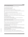
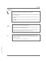
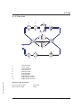
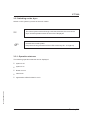
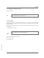
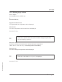
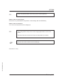
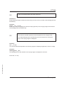
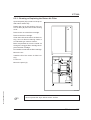
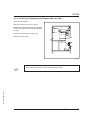
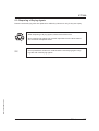
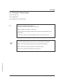
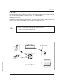
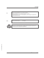
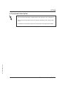
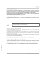
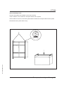
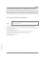
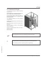
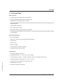
1
Operating Instructions
64.10-0260GB05 06/03
Dehumidified air dryer
CTT 250
with Siemens S7 control unit
Colortronic GmbH
CTT 250
Colortronic GmbH
Otto-Hahn-Straße 10-14
61381 Friedrichsdorf
USA
Colortronic North America Inc.
155 E. 9th Avenue
Runnemede, NJ 08078
Telephone (0 61 75) 7 92-0
Telefax (0 61 75) 7 92-1 79
Email [email protected]
Http://www.colortronic.com
Telephone (856) 312-9600
Telefax (856) 312-9696
Email [email protected]
Technical service:
Service department
Telephone: (0 61 75) 7 92-2 22
Telefax: (0 61 75) 7 92-1 19
Email [email protected]
Spare parts department
Telephone: (0 61 75) 7 92-3 33
Telefax: (0 61 75) 7 92-1 08
Edition: 06/03
Order-No: 64.10-0260GB05
These operating instructions are for*:
(* Please fill in personally)
Serial number:
Year of manufacture:
Date of delivery:
64.10-0260GB05 06/03
Number of delivery:
Date of commissioning:
Location:
Group of machines:
2
CTT 250
64.10-0260GB05 06/03
Colortronic GmbH retains all rights to change the information in these operating
instructions at any time without notice.
We assume no liability for any errors or direct or indirect damage resulting in context with these operating instructions.
Copying, translation or publication in any form except for personal use of purchaser requires approval from Colortronic GmbH.
All rights reserved.
3
CTT 250
Table of contents
1. General Information . . . . . . . . . . . . . . . . . . . . . . . . . . . . . . . . . . . . . . . . . . . . . . . . . . . . . . . 1-1
1.1.
1.2.
1.3.
1.4.
1.5.
Warnings and symbols . . . . . . . . . . . . . . . . . . . . . . . . . . . . . . . . . . . . . . . . . . . . 1-2
Explanations and information . . . . . . . . . . . . . . . . . . . . . . . . . . . . . . . . . . . . . . . 1-4
Legal basis . . . . . . . . . . . . . . . . . . . . . . . . . . . . . . . . . . . . . . . . . . . . . . . . . . . . . . 1-4
Fields of applications. . . . . . . . . . . . . . . . . . . . . . . . . . . . . . . . . . . . . . . . . . . . . . 1-4
Notes on Usage . . . . . . . . . . . . . . . . . . . . . . . . . . . . . . . . . . . . . . . . . . . . . . . . . . 1-4
2. Safety instructions. . . . . . . . . . . . . . . . . . . . . . . . . . . . . . . . . . . . . . . . . . . . . . . . . . . . . . . . 2-1
2.1. For your safety . . . . . . . . . . . . . . . . . . . . . . . . . . . . . . . . . . . . . . . . . . . . . . . . . . . 2-2
2.2. For the safety of the devices. . . . . . . . . . . . . . . . . . . . . . . . . . . . . . . . . . . . . . . . 2-5
64.10-0260GB05 06/03
3. Start-up . . . . . . . . . . . . . . . . . . . . . . . . . . . . . . . . . . . . . . . . . . . . . . . . . . . . . . . . . . . . . . . . . 3-1
3.1. Control system . . . . . . . . . . . . . . . . . . . . . . . . . . . . . . . . . . . . . . . . . . . . . . . . . . . 3-2
3.1.1. Key assignment . . . . . . . . . . . . . . . . . . . . . . . . . . . . . . . . . . . . . . . . . . . 3-2
3.1.2. Flow chart . . . . . . . . . . . . . . . . . . . . . . . . . . . . . . . . . . . . . . . . . . . . . . . . 3-3
3.2. Switching on the dryer. . . . . . . . . . . . . . . . . . . . . . . . . . . . . . . . . . . . . . . . . . . . . 3-4
3.2.1. Operation statuses . . . . . . . . . . . . . . . . . . . . . . . . . . . . . . . . . . . . . . . . . 3-4
3.3. Viewing the software-version . . . . . . . . . . . . . . . . . . . . . . . . . . . . . . . . . . . . . . . 3-5
3.4. Passwords . . . . . . . . . . . . . . . . . . . . . . . . . . . . . . . . . . . . . . . . . . . . . . . . . . . . . . 3-5
3.5. Basic parameters . . . . . . . . . . . . . . . . . . . . . . . . . . . . . . . . . . . . . . . . . . . . . . . . . 3-7
3.5.1. Turning the devices on/off . . . . . . . . . . . . . . . . . . . . . . . . . . . . . . . . . . . 3-7
3.5.2. Entering dryer values . . . . . . . . . . . . . . . . . . . . . . . . . . . . . . . . . . . . . . . 3-9
3.5.3. Entering hopper values . . . . . . . . . . . . . . . . . . . . . . . . . . . . . . . . . . . . 3-11
3.5.3.1. Entering drying hopper names . . . . . . . . . . . . . . . . . . . . . . . . 3-13
3.5.3.2. Entering dwelling time . . . . . . . . . . . . . . . . . . . . . . . . . . . . . . 3-14
3.5.4. Observing processing status . . . . . . . . . . . . . . . . . . . . . . . . . . . . . . . . 3-15
3.5.5. Setting date and time . . . . . . . . . . . . . . . . . . . . . . . . . . . . . . . . . . . . . . 3-16
3.5.6. Viewing/changing language and contrast . . . . . . . . . . . . . . . . . . . . . . 3-17
3.5.7. Changing parameters. . . . . . . . . . . . . . . . . . . . . . . . . . . . . . . . . . . . . . 3-18
3.5.8. Setting the timer . . . . . . . . . . . . . . . . . . . . . . . . . . . . . . . . . . . . . . . . . . 3-19
3.6. Starting continuous operation . . . . . . . . . . . . . . . . . . . . . . . . . . . . . . . . . . . . . . 3-20
3.7. Viewing system runtime . . . . . . . . . . . . . . . . . . . . . . . . . . . . . . . . . . . . . . . . . . 3-21
3.8. Switching the dryer off. . . . . . . . . . . . . . . . . . . . . . . . . . . . . . . . . . . . . . . . . . . . 3-22
4. Error and error correction . . . . . . . . . . . . . . . . . . . . . . . . . . . . . . . . . . . . . . . . . . . . . . . . . 4-1
4
CTT 250
5. Maintenance . . . . . . . . . . . . . . . . . . . . . . . . . . . . . . . . . . . . . . . . . . . . . . . . . . . . . . . . . . . . . 5-1
5.1. Maintenance schedule. . . . . . . . . . . . . . . . . . . . . . . . . . . . . . . . . . . . . . . . . . . . . 5-3
5.2. Cleaning or Replacing the Air Filters . . . . . . . . . . . . . . . . . . . . . . . . . . . . . . . . . 5-4
5.2.1. Cleaning or Replacing the Return Air Filter . . . . . . . . . . . . . . . . . . . . . 5-5
5.2.2. Cleaning or Replacing the Regeneration air filter . . . . . . . . . . . . . . . . 5-6
5.3. Disposing of Drying Agents. . . . . . . . . . . . . . . . . . . . . . . . . . . . . . . . . . . . . . . . . 5-7
5.4. Cleaning the Drying Hopper . . . . . . . . . . . . . . . . . . . . . . . . . . . . . . . . . . . . . . . . 5-8
5.5. Changing the battery of the control system . . . . . . . . . . . . . . . . . . . . . . . . . . . 5-11
5.5.1. Resetting the control values . . . . . . . . . . . . . . . . . . . . . . . . . . . . . . . . 5-13
6. Functional description . . . . . . . . . . . . . . . . . . . . . . . . . . . . . . . . . . . . . . . . . . . . . . . . . . . . 6-1
6.1. General Information . . . . . . . . . . . . . . . . . . . . . . . . . . . . . . . . . . . . . . . . . . . . . . . 6-2
6.2. Drying Hopper (Optional) . . . . . . . . . . . . . . . . . . . . . . . . . . . . . . . . . . . . . . . . . . 6-3
6.2.1. Hopper heaters (optional) . . . . . . . . . . . . . . . . . . . . . . . . . . . . . . . . . . . 6-3
6.3. Connection to a Pneumatic Conveying System (Optional) . . . . . . . . . . . . . . . . 6-4
6.4. Return Air Cooler (Optional) . . . . . . . . . . . . . . . . . . . . . . . . . . . . . . . . . . . . . . . . 6-4
7. Transport, Assembly and Storage. . . . . . . . . . . . . . . . . . . . . . . . . . . . . . . . . . . . . . . . . . . 7-1
7.1. Tansport and Packing . . . . . . . . . . . . . . . . . . . . . . . . . . . . . . . . . . . . . . . . . . . . . 7-2
7.2. Assembly . . . . . . . . . . . . . . . . . . . . . . . . . . . . . . . . . . . . . . . . . . . . . . . . . . . . . . . 7-4
7.3. Storage . . . . . . . . . . . . . . . . . . . . . . . . . . . . . . . . . . . . . . . . . . . . . . . . . . . . . . . . . 7-4
8. Assembly instructions . . . . . . . . . . . . . . . . . . . . . . . . . . . . . . . . . . . . . . . . . . . . . . . . . . . . 8-1
8.1.
8.2.
8.3.
8.4.
Installation of the exhauster fan for regeneration of exhaust air . . . . . . . . . . . 8-2
Connection of Return Air Cooler (Optional) . . . . . . . . . . . . . . . . . . . . . . . . . . . . 8-2
Electrical Connection. . . . . . . . . . . . . . . . . . . . . . . . . . . . . . . . . . . . . . . . . . . . . . 8-3
Compressed Air Supply. . . . . . . . . . . . . . . . . . . . . . . . . . . . . . . . . . . . . . . . . . . . 8-4
64.10-0260GB05 06/03
9. Technical Data . . . . . . . . . . . . . . . . . . . . . . . . . . . . . . . . . . . . . . . . . . . . . . . . . . . . . . . . . . . 9-1
5
CTT 250
10. Spare parts list . . . . . . . . . . . . . . . . . . . . . . . . . . . . . . . . . . . . . . . . . . . . . . . . . . . . . . . . . 10-1
10.1. Switching Cabinet and Operating Unit . . . . . . . . . . . . . . . . . . . . . . . . . . . . . . 10-4
10.2. Drying Hopper . . . . . . . . . . . . . . . . . . . . . . . . . . . . . . . . . . . . . . . . . . . . . . . . . 10-4
11. Electrical manual . . . . . . . . . . . . . . . . . . . . . . . . . . . . . . . . . . . . . . . . . . . . . . . . . . . . . . . 11-1
o Connection diagram no.: _ _ _ _ _ _ _ _ _ _ _ _ _ _ _ _
o Currently not available; will be delivered at a later date!
12. Accessories . . . . . . . . . . . . . . . . . . . . . . . . . . . . . . . . . . . . . . . . . . . . . . . . . . . . . . . . . . . 12-1
o Spare parts list Drying Hoppers TT 25 - TT 6400
o Entering values on the OP 7 / 17
o Flap control with Fuzzy-Logic
o _____________________________
64.10-0260GB05 06/03
o _____________________________
6
CTT 250
1. General Information
These operating instructions must be used by every person charged with
work on the unit.
64.10-0260GB05 06/03
»
These operating instructions are addressed to all users of the device.
General Information 1-1
CTT 250
1.1. Warnings and symbols
The following warnings and symbols are used in these operating instructions:
»
This symbol indicates danger to life! Fatal or serious injury is possible if the
corresponding instructions, regulations or warnings are not observed.
This symbol indicates that serious injury is possible if the corresponding
instructions, regulations or warnings are not observed.
F
This symbol indicates that extensive damage to equipment is possible if
the corresponding instructions, regulations or warnings are not observed.
&
This symbol indicates information important for becoming familiar with
the equipment, i.e. technical correlations.
$
This symbol indicates that a technical term is explained at this point.
64.10-0260GB05 06/03
L
General Information 1-2
CTT 250
When disposing of drying agents / batteries / oil, observe all official rules.
Caution: High noise pollution!
For all work on the equipment, hearing protection should be worn.
Avoids impairment of hearing!
Caution: Danger of crushing!
Disconnect the equipment from mains supply before starting mainenance procedures. All compressed air pipes on the equipment should be depressurised before starting maintenance work.
Caution: Danger of hot surface!
Before starting any work wait until all parts have been cooled down sufficiently. Avoid touching any of these parts!
64.10-0260GB05 06/03
Caution: Danger of skidding!
Remove any granules remaining on the ground.
Caution: Danger to life through electrical shock!
Observe that the control system is still under voltage even when the main
switch is switched off.
General Information 1-3
CTT 250
1.2. Explanations and information
Various terms and designations are used in these operating instructions to ensure clarity. Therefore please note that the terms used in the text stand for the corresponding explanations listed below.
•
Equipment
”Equipment” can mean an individual unit, a machine or an installation.
•
Operating personnel
The ”operating personnel” are persons operating the equipment on their own responsibility or according to instructions.
•
Operator
The ”operator” of the equipment (production manager, foreman, etc.) is the person responsible for
all production sequences. The operator instructs the operating personnel of what is to be done.
•
Operating instructions
The ”operating instructions” describe the interaction of the equipment, production sequences or
methods. The operating instructions must be compiled by the operator of the equipment.
•
Equipment foreman
When several operating personnel work on one machine, the ”equipment foreman” coordinates
the sequences. The equipment foreman must be appointed by the operator.
•
Trained personnel
”Trained personnel” are persons who, due to their training, are authorized to carry out the required
work.
1.3. Legal basis
See “Manufacturer’s Certificate” resp. “Certificate of Conformity”.
1.4. Fields of applications
For the drying of thermoplastic granules and regrind before processing in order to remove all remaining moisture from the granules both inside and out, independent of climate or ambient air
conditions.
64.10-0260GB05 06/03
1.5. Notes on Usage
•
Experienced operators can begin directly with the chapter on “Start-up” if the unit has been properly installed.
•
If the unit has not been installed yet, observe the instructions in the chapter on “Assembly Instructions” and “Transport, Assembly and Storage”.
General Information 1-4
CTT 250
2. Safety instructions
»
These safety instructions apply to all persons within the range of action of the
equipment.
Please inform all persons within the range of action of the equipment of the
direct and indirect hazards connected with the equipment.
These operating instructions are to be used by all persons assigned activities
connected with the equipment.
Knowledge of the English language is prerequisite.
64.10-0260GB05 06/03
Ensure in each case that the operating personnel are familiar with the operating instructions and the function of the equipment.
Safety instructions 2-1
CTT 250
2.1. For your safety
General
The operating personnel of this equipment must be at least 16 years old.
Please read these operating instructions carefully before taking into operation for the first time.
Contact us should questions arise. This avoids injury and damage to equipment!
These operating instructions must be kept available at all times at the place of operation of the
equipment. Improper operation results in danger of accidents!
Please note that, for reasons of clarity, not all conceivable cases regarding operation or maintenance of the equipment can be covered in these operating instructions.
Please observe all safety instructions and warnings on the equipment. This avoids injury and damage to equipment!
All work on the equipment is to be carried out by persons whose qualifications are specified in the
pertaining chapters of the operating instructions. Improper operation results in danger of accidents!
The proper working clothes are to be worn during any work on the equipment. This avoids injury!
The local regulations and requirements pertaining to this equipment must be observed.
Disconnect electrical components from the mains supply before work is carried out on these components Caution: Danger to life through electrical shock!
Compile detailed operating instructions based on these Operating instructions for the sequence
of procedures to be carried out on this equipment. Improper operation results in danger of accidents!
64.10-0260GB05 06/03
Observe that the control system is still under voltage even when the main switch is switched off.
Caution: Danger to life through electrical shock!
Safety instructions 2-2
CTT 250
Assembly
Compare the connected loads with those of the mains supply. Danger of injury through electrical
shock!
When using lifting gear, please observe the pertaining regulations. Caution: Danger of accidents!
Do not modify, add other equipment or change the design of the equipment without the approval
of the manufacturer. Caution: Danger of accidents!
Attachments not supplied by Colortronic must be manufactured in accordance with safety regulation EN 294. Danger of accidents!
The equipment may only be operated when all the associated components are properly connected up and in accordance with the relevant regulations. This avoids injury and damage to equipment!
Operate the device only if all its components are grounded. Danger: accident through electrical
shock!
Please note for installation that the equipment is top-heavy. Danger exists that it may topple over!
Take care that the device is not standing on the mains cable. This will prevent danger to people
and material!
Operation
Appoint an equipment foreman to be responsible for the equipment.
Ensure that the operating personnel are provided detailed instruction in the operation of the
equipment. Improper operation results in danger of accidents!
When the main switch is switched off for reasons pertaining to safety, it must be secured against
unauthorized activation. Caution: Danger of accidents!
Repair work may be carried out by trained personnel only. Caution: Danger of accidents!
Never operate the equipment when partially dismantled! Danger! Limbs may be caught in machinery! Electric shock!
In case of malfunction, shut down the equipment immediately. Have malfunctions corrected immediately. Danger of accidents!
The machine is intended only for the drying of granulated plastics. Any other or additional use is
contrary to specifications.
This equipment is not suitable for food processing.
64.10-0260GB05 06/03
The safety instructions of the connected machines must be followed.
Please note that sound levels exceeding 85 db(A) may in the long term damage your health. Use
the appropriate ear muffs. This avoids impairment of hearing!
Please note that the drying cells, drying hoppers and air pipings grow hot during use. Avoid touching any of these parts! Danger: Injury through burns!
Never operate the dryer without side panels. Danger: Limbs may be caught in machinery! Injury
through burns!
Safety instructions 2-3
CTT 250
When drying plastics which emit gases dangerous for human health, take care that the regeneration exhaust air is disposed of without polluting the environment. This will prevent danger to people and material!
Operate the dryer only if there is at least one drying hopper operating. This will prevent damage of
material!
Maintenance
Before starting maintenance work, appoint a supervisor.
Inform the responsible personnel before maintenance work on the system is started. Caution:
Danger of accidents!
Disconnect the equipment from mains supply before starting maintenance procedures to ensure
that it cannot be switched on unintentionally. Caution: Danger of accidents!
All pipes, hoses and screwed connections should be checked regularly for leaks and damage.
Any faults which arise should be corrected immediately. Danger of accidents!
Depressurise all compressed air piping before starting maintenance work. Danger of accidents!
The air filters should only be cleaned/replaced when the the main switch is off and the blower has
stopped. This avoids injury and damage to equipment!
Any maintenance work on the equipment should only be started when the the main switch is off
and the blower has stopped. This avoids injury and damage to equipment!
Check the v-belts of the blower only when the main switch is switched off and the blowers have
stopped. Caution: Danger of accidents!
Open drying hoppers only if they are completely empty. Danger of accidents!
Never open drying hoppers while the device is in operation. Danger: Iinjury through burns!
Open drying hoppers only if they have been cooled down sufficiently. Danger: Injury through
burns!
Before starting maintenance work wait until the drying cells, drying hoppers and air pipings have
been cooled down sufficiently. Avoid touching any of these parts! Danger: Injury through burns!
Remove any granules remaining on the ground. Danger of accidents!
64.10-0260GB05 06/03
Arrest the wheels after installation if the dryer is mounted on a movable frame. This will prevent
danger to people and material!
Safety instructions 2-4
CTT 250
2.2. For the safety of the devices
Never change settings without carefully assessing the consequences.
Use only original Colortronic spare parts.
Observe the maintenance instructions.
Keep a record of all maintenance works and repairs.
Please note that electronic components can be damaged by static discharge.
Before initial operation and in regular intervals, make sure that no electrical connections are loose.
Never readjust sensors without exactly knowing their functions.
Please ensure that the permitted storage temperature lies between -20 and +55 °C
(-4 to +131 °F).
Please ensure that the permitted operation temperature lies between 0 and +45 °C
(32 to +113 °F).
Check the direction of rotation of the blowers after the electrical connections have been made
(see rotational direction arrow).
Clean the drying hoppers before the first filling.
Note the instructions of the material manufacturer for the maximum drying temperature.
Note the drying instructions of the material manufacturer.
Take care that the drying hoppers are always completely filled and that the retention period is respected if continual removal is taking place.
Note that too large amounts taken from the drying hopper lead to insufficient drying of the material.
Close the air stop valves of drying hoppers which are empty or have not been used.
Note down all data which you have entered into the control system.
The password is to be entrusted to authorised personnel only.
Please note that the temperature of the dryer heating system must always be set lower than that of
the supplementary heaters.
When you dispose of drying agents, observe all official rules.
64.10-0260GB05 06/03
Note that drying cells are replaced or refilled by Colortronic only if they are empty.
The material level may not fall below 40 % in the drying hopper, when material is continuously removed from the drying hopper, but no material is continuously fed into the drying hopper (batch
drying). Close the throttle valves.
Read the operating manuals of the connected devices.
Please note that a compressed air supply is required for the operation of the unit.
Never set a higher operating pressure than 6 bar for the hopper loaders (system overpressure).
Safety instructions 2-5
CTT 250
3. Start-up
»
This chapter is directed at the operators of the equipment.
This chapter assumes general skills in dealing with drying systems and SPS
(PLC) control units.
This chapter assumes that the functional description has been read and understood.
It should be ensured in each and every case that the operators have the relevant skills.
F
Note down all set values of the control system.
Make sure that the cooling appliance is connected to the mains socket in
the electrical cabinet (if present, optional).
Make sure that any condensate penetrating from the cooling appliance
(optional) does not get inside the dryer or the control box.
&
If the inside temperature of the switch cabinet is above +50°C (122 °F),
the dryer is switched off after 30 minutes if it is operated with a cooling
appliance (optional).
64.10-0260GB05 06/03
If ordered temperature can be displayed in °F !
Start-up 3-1
CTT 250
3.1. Control system
The control system is switched on at the main switch. The control system is operated via a
”selection window” and the keyboard of the operator panel.
The facility’s control system is factory-programmed. Nevertheless, you have to set specific
values (basic parameters) which are dependent on the processed material, for instance.
The values entered are stored in the control system and remain so, even after the unit is switched
off or in the event of a power cut. All messages are displayed in plain text.
In describing this start-up, we have assumed that the various sub-menus are selected from the
”table of contents”.
This structure of the description has been selected since, in most cases, you will only work on one
item in the ”submenu”.
If you want to work on several ”submenu” items in succession, you can select the individual items
directly by means of the arrow keys.
64.10-0260GB05 06/03
3.1.1. Key assignment
F1-key:
Leads to the table of contents.
ENTER-key:
Confirms the entries.
ESC-key:
Goes back one step in the menu.
ACK-key:
Activates an alarm message; to unblock the control system.
Arrow keys:
Move the cursor bar;
switch the appliances on or off in combination with the SHIFT key;
for scrolling forward or backward in a menu.
SHIFT-key:
Switches on the secondary functions of the keys,
when the SHIFT-key has been pushed, the LED “SHIFT” is on.
HELP-key:
Viewing additional texts,
when additional texts can be viewed the LED “HELP” is on.
LED “ALARM”:
flashes in case of an error;
is on if the error has been acknowledged but not yet
eliminated; is off if there are no errors
&
LED = light emitting diode
An additional alarm device (horn or lamp) can be connected (optional).
Start-up 3-2
CTT 250
3.1.2. Flow chart
4
5
6
7
3
2
2
3
10
64.10-0260GB05 06/03
1
2
3
4
5
6
7
8
9
10
9
8
Indicator lamp
Valve system
Drying chamber
Drying blower
Return air filter
Drying hopper
Drying heater
Regeneration heater
Regeneration blower
Regeneration air filter
Indicator lamp messages:
Green continous light:
Red continous light:
in process
alarm
Start-up 3-3
CTT 250
3.2. Switching on the dryer
Switch on the system by means of the main switch.
&
F
The control system carries through a self-test; after that, the name of the
dryer and the operation status of the unit are displayed.
Unblock the control system:
Keep the ACK key pressed until the LEDs of the keys K1 - K4 light up.
3.2.1. Operation statuses
The following operation statuses can be displayed:
system is off
•
system is on
•
blower runs on
•
valve block
•
regeneration will be finished in x min.
64.10-0260GB05 06/03
•
Start-up 3-4
CTT 250
3.3. Viewing the software-version
Press the “±”-key.
&
The software-version will be displayed.
3.4. Passwords
The entry of a password prevents unauthorised persons from having access to the data entered
into the control system. Important data can then be entered or modified only after the password
has been entered.
If you make no entries for more than 10 minutes, the access is blocked and you have to re-enter
the password.
•
password level 6: 79 21 54
F
Tell the password only to authorised persons.
Press the ”Shift”-key and the ”K4”-key.
Press 3 x the “â” key.
64.10-0260GB05 06/03
Press the ”F3”-key.
Start-up 3-5
CTT 250
Login
Press the key “F2".
Enter the password.
Press the ENTER key.
&
If the password has been entered correctly, the corresponding password
level is displayed.
You can now enter data into the control system or modify data which have
already been entered.
Press the ESC key.
Logout
Press the key “F3".
&
Only data for which no password is necessary (= password level 0) can
now be entered into the control system or modified.
Press the “â“ key.
Edit
Press the key “F2".
64.10-0260GB05 06/03
&
This function is available only for password level 9.
Passwords and password levels can be modified or entered.
Confirm your entries by means of the ENTER key.
Press the ”F1"-key.
Start-up 3-6
CTT 250
3.5. Basic parameters
Press the ”F1"-key.
3.5.1. Turning the devices on/off
Select ”Main menu”.
Acknowledge with the ENTER-key.
or
Press the ”F2”-key.
Dryer on/off
”on” = turn dryer on, ”off” = turn dryer off.
Acknowledge with the ENTER-key.
Timer on/off
Press the SHIFT-key and choose with the arrow-keys the desired operation:
”internal” = operation with timer (operation at OP7, see chapter timer),
“external” = operation with timer (if present),
”off” = operation without timer.
Acknowledge with the ENTER-key.
&
The timer is only operating, when the dryer is switched on.
Press the “â” key.
64.10-0260GB05 06/03
&
If the unit operates with a return resp. pre air cooler (optional):
Return / Pre air cooler on/off
Press the SHIFT-key and choose with the arrow-keys the desired operation:
“on” = operation with pre air cooler, “off” = operation without pre air cooler. Acknowledge with the
ENTER-key.
Press the “â” key.
Start-up 3-7
CTT 250
Hopper #
on/off
#: Select the drying hopper that you wish to enable or disable. Press the ENTER key.
“on”/ “off”: Press the SHIFT key. Using the arrow-keys enter “ON” if you want to enable the drying hopper. Enter “OFF” if you want to disable the drying hopper. Press the ENTER key.
Hopper heater
on/off
Press the SHIFT key. Using the arrow-keys enter “ON” if you want to switch on hopper heater. Enter “OFF if you want to switch off hopper heater. Acknowledge with the ENTER-key.
64.10-0260GB05 06/03
Press the ”F1"-key.
Start-up 3-8
CTT 250
3.5.2. Entering dryer values
Select ”Dryer”.
Acknowledge with the ENTER-key.
or
Press the ”F3”-key.
Regeneration Heater Act.
The regenerated heat temperature will be displayed.
Used air Act.
The current temperature of the used air will be displayed.
Press the “â” key.
&
If the unit is operates with “dew point controlled changeover point with
dew point display” (optional):
Dew point max.
Enter the maximum permissible (worst allowed) dew point temperature
(-35 to -28 °C / -31 to -18.4 °F). Acknowledge with the ENTER-key.
Dew point Act.
The current dew point temperature will be displayed.
&
If there is a cable break “+0 °C (32 °F)” is displayed.
64.10-0260GB05 06/03
Press the “â” key.
Start-up 3-9
CTT 250
&
If the unit operates with a return resp. pre air cooler (optional):
Return / Pre air cooler Target
Enter the max. permissible air temperature. Acknowledge with the ENTER-key.
Return / Pre air cooler Act.
The current air temperature will be displayed.
&
The cooling effect of the pre air cooler is highly dependent on the cooler
circuit.
The lower the value chosen for the pre air temperature, the better.
F
Plan the size of the coolant circuit accordingly.
64.10-0260GB05 06/03
Press the ”F1"-key.
Start-up 3-10
CTT 250
3.5.3. Entering hopper values
Select ”Hopper”.
Acknowledge with the ENTER-key.
or
Press the ”F4”-key.
Hopper entry #
Enter the drying hopper number whoose value you want to view or modify. Acknowledge with the
ENTER-key.
Hopper entry Target
Enter the drying temperature for the drying hopper (when operating with supplementary heating).
Acknowledge with the ENTER-key.
Hopper entry Act.
The current temperature at the feed opening of hopper flap will be displayed.
&
F
If there is a cable break “+0 °C (32 °F)” is displayed.
The lowest drying temperature setting of the hopper flap must be the
same as or higher than the drying temperature.
Name TT: ########
Display of drying hopper (TT) name.
64.10-0260GB05 06/03
Press the “â” key.
Start-up 3-11
CTT 250
&
If the unit operates with motor flaps (optional):
Granules #
Enter the drying hopper number whoose value you want to view or modify. Acknowledge with the
ENTER-key.
Granules
target: _ % = _ °C (°F)
Enter the material temperature at which the flap (optional) on the drying hopper should close.
Acknowledge with the ENTER-key.
&
This value is entered in percent of the temperature on the hopper inlet.
The material temperature calculated by the control system for closing the
flap on the drying hopper is displayed.
Granules
act.: _ °C (°F)
The current material temperature in the drying hopper is displayed (optional, if there is a flap).
Granules
dwelling time: _ min
The dwelling time of the material in the drying hopper is displayed in minutes.
64.10-0260GB05 06/03
Press the ”F1"-key.
Start-up 3-12
CTT 250
3.5.3.1. Entering drying hopper names
&
This function is password protected.
Press the SHIFT-key and the ”F3”-key.
Enter the password if requested.
Hopper #
Enter the drying hopper number. Acknowledge with the ENTER-key.
Name TT: ########
Enter the drying hopper name. Acknowledge with the ENTER-key.
64.10-0260GB05 06/03
Press the ”F1"-key.
Start-up 3-13
CTT 250
3.5.3.2. Entering dwelling time
&
This function is password protected.
Press the SHIFT-key and the ”F3”-key.
Enter the password if requested.
Hopper #
Enter the drying hopper number. Acknowledge with the ENTER-key.
Dwelling time: _ min
Enter the dwelling time of the material within the drying hopper in minutes. Acknowledge with the
ENTER-key.
F
&
Observe the indicated dwelling time.
When the drying hopper is released, the dwelling time starts. The residual time is displayed (= current dwelling time).
If the drying hopper is blocked, the current dwelling time is reset to the
value of the dwelling time which has been entered before.
64.10-0260GB05 06/03
Press the ”F1"-key.
Start-up 3-14
CTT 250
3.5.4. Observing processing status
Select ”Status”.
Acknowledge with the ENTER-key.
or
Press the ”K1”-key.
&
The current operation status of individual assembly parts is displayed:
e.g.: valve block moved in/moved out/error
“moved in” = The upper drying cells are within the drying circuit; the lower
ones are regenerated.
“moved out” = The upper drying cells are regenerated; the lower ones are
within the drying circuit.
“error” = An error has occurred.
Other operation statuses:
“on” = in operation,
“off” = out of operation,
“open” = opened,
“shut” = closed.
64.10-0260GB05 06/03
Press the “F1"-key.
Start-up 3-15
CTT 250
3.5.5. Setting date and time
&
This function is password protected.
Press the “K3"-key.
Enter the password if requested.
Date
Press the SHIFT key.
By means of the arrow keys, select the desired week-day.
By means of the arrow keys, select the shown date.
Press the SHIFT key.
Enter the desired date.
Press the ENTER key.
Time
Enter the desired time.
Press the ENTER key.
64.10-0260GB05 06/03
Press the ”F1”-key.
Start-up 3-16
CTT 250
3.5.6. Viewing/changing language and contrast
&
This function is password protected.
Press the “K4"-key.
Enter the password if requested.
Contrast
Press the SHIFT key.
By means of the arrow keys, select the adjustment which suits you best. Press the ENTER key.
&
Depending on the outside temperature, the brightness of the screen may
vary.
Language
Press the SHIFT key.
By means of the arrow keys, select the desired language (if present). Press the ENTER key.
64.10-0260GB05 06/03
Press the “F1"-key.
Start-up 3-17
CTT 250
3.5.7. Changing parameters
Select ”Parameters”.
Acknowledge with the ENTER-key.
or
Press the SHIFT-key and the ”K1”-key.
Run on time
drying blower
-- 300 sec.
Standard setting: 300 seconds, changes only after contacting Colortronic Service.
Press the “â” key.
Parameters
F
The values in this menu may only be changed after contacting
Colortronic Service.
64.10-0260GB05 06/03
Press the ”F1"-key.
Start-up 3-18
CTT 250
3.5.8. Setting the timer
Select ”Timer”.
Acknowledge with the ENTER-key.
or
Press the SHIFT-key and the ”F1”-key.
XX ON 00:00 OFF 00:00 (XX = day Mo-Su)
Enter for each day the switching on time and the switching off time.
Acknowledge with the ENTER-key.
&
Example:
Timer
fr
sa
su
mo
ON
08:00
00:00
20:00
00:00
OFF
23:59
23:59
08:00
00:00
The dryer starts on Friday at 08:00 in the morning, runs through without
interruption until sunday at 08:00 and switches off. At 20:00 the dryer
starts again and switches off on Monday at 00:00.
64.10-0260GB05 06/03
Press the ”F1"-key.
Start-up 3-19
CTT 250
3.6. Starting continuous operation
When you have carried through all basic settings, you can start with continuous operation.
F
Make sure that hoppers which are not in use are separated from the dehumidified air supply.
Make sure that the set drying temperatures are suited for the materials in
the hoppers.
After first filling, do not process the material until after the dwelling time.
If a return air cooler (optional) is installed, switch on the coolant circuit .
If a pre air cooler (optional) is installed, switch on the coolant circuit.
Make sure that the cooling appliance is connected to the mains socket (if
present, optional).
Check setting of the timer.
Select ”Main menu”.
Acknowledge with the ENTER-key.
or
Press the ”F2”-key.
Select ”Dryer on”.
64.10-0260GB05 06/03
Acknowledge with the ENTER-key.
Start-up 3-20
CTT 250
3.7. Viewing system runtime
Select ”System runtime”.
Acknowledge with the ENTER-key.
or
Press the SHIFT-key and the ”F2”-key.
System runtime
PLC
#.## h
r.-blwr.
#.## h
m.-blwr.
#.## h
The runtime of the blowers and the PLC (SPS) is shown in hours.
64.10-0260GB05 06/03
&
Start-up 3-21
CTT 250
3.8. Switching the dryer off
Select ”Main menu”.
Acknowledge with the ENTER-key.
or
Press the ”F2”-key.
Select ”Dryer off”.
Acknowledge with the ENTER-key.
L
Wait until the regeneration phase is finished and the blower has come to
a standstill.
Switch off the dryer at the main switch.
Disconnect the power supply.
64.10-0260GB05 06/03
F
Never switch off the dryer directly at the main switch.
Start-up 3-22
CTT 250
4. Error and error correction
»
This chapter is directed at the operators of the equipment.
This chapter assumes general skills in dealing with drying systems and SPS
(PLC) control units.
This chapter assumes that the “start-up” description has been read and understood.
64.10-0260GB05 06/03
It should be ensured in each and every case that the operators have the relevant skills.
Error and error correction 4-1
CTT 250
&
Alarm messages are displayed in plain language on the screen of the
operator device.
The display of alarm messages in the operator device can only be erased
by pressing the ”ACK” key. The failure is not repaired.
A failure is given by flashing of the LED “alarm”. If the alarm message is
acknowledged by pressing of the “ACK” key, but the failure is not yet eliminated, the flashing changes to steady light.
If a cooling appliance is present: If the temperature inside the switch box
is higher than +50 °C, the lamp ”alarm - temperature inside switch box”
goes on. If the temperature is still too high after 30 minutes, the dryer is
switched off.
F
Failures must be repaired immediately.
LED “ALARM”:
flashes in case of an error;
is on if the error has been acknowledged but not yet eliminated;
is off if there are no errors
64.10-0260GB05 06/03
Press the ”K2"-key.
Error and error correction 4-2
CTT 250
View
Press the ”F2"-key.
All alarm messages with their numbers (see Texts), date, time and the supplement ”K”, ”G”, or ”Q”
are displayed.
&
”K” = coming (a failure occured)
Pressing the “à”-key displays the alarm message in plain text.
”G” = going (the resent for the failure has gone)
”Q” = reset (the display of the alarm message in the operator
device has been erased by pressing the ”ACK”-key)
Press the ESC-key.
Print (Optional)
&
F
This function is password protected.
Make sure that a printer is connected and switched on.
Press the ”F3"-key.
64.10-0260GB05 06/03
The alarm messages are printed.
Press the “â”-key.
Error and error correction 4-3
CTT 250
Number
Press the ”F2"-key.
Total messages
The number of all alarm messages is displayed.
Waiting messages
The number of current alarm messages is displayed.
Press the ESC-key.
Delete
Press the ”F3"-key.
&
This function is password protected (Colortronic service).
Press the ENTER-key for deleting the messages.
Press the ESC-key.
64.10-0260GB05 06/03
Press the “â”-key.
Error and error correction 4-4
CTT 250
Overflow
Press the ”F2"-key.
&
If there are more current alarm messages than can be saved, a warning
message (= residual buffer reached) may be given.
This function is password protected (Colortronic service).
Overflow warning On/Off
Press the SHIFT-key.
By means of the arrow keys, select ”on” if a warning message is to be given.
By means of the arrow keys, select ”off” if no warning message is to be given.
Press the ENTER-key.
F
If the overflow warning message is given, press the ACK-key. Delete the
alarm messages.
64.10-0260GB05 06/03
Press the ESC-key.
Error and error correction 4-5
CTT 250
Text
Press the ”F3"-key.
All possible alarm messages are displayed with their numbers (see Viewing).
For viewing the possible alarm messages, press the arrow keys:
PLC (= SPS) Battery is Empty
Replace the SPS battery.
Main Switch is Off
The main switch has been placed in the off position.
The safety temperature limiter of the drying or the regeneration heater, respectively, has been activated.
The safety temperature limiter of a hopper heater has been activated.
Error valve block.
Check the safety temperature limiter.
Check the position of the valve block.
A Safety Temperature Limiter has been Activated
Check the safety temperature limiter of the drying, regeneration, or hopper heater, respectively.
Filter Door is Open
The side panels to the air filters are open.
Assemble side panels.
The Safety Switch Regeneration Blower Has Been Actuated
Check the blower.
Check the fuses.
Short circuit check of the blower.
Vacuum Regeneration Blower
The regeneration blower does not produce sufficient pressure.
64.10-0260GB05 06/03
Check the blower.
Vacuum sensor defective.
The Safety Switch Drying Blower Has Been Actuated
Check the blower.
Check the fuses.
Short circuit check of the blower.
Vacuum Drying Blower
The drying blower does not produce sufficient pressure.
Check the blower.
Vacuum sensor defective.
Error and error correction 4-6
CTT 250
Temperature Measurement Regeneration Heater Defective
Check the cables and the sensor.
Check the power supply.
Short circuit check.
Excess Temperature Regeneration Heater
The regeneration temperature is too high.
Check the safety temperature limiter.
Colortronic Service.
Insufficient Temperature Regeneration Heater
The regeneration temperature is too low.
Check the regeneration heater.
The Safety Switch Regeneration Heater Has Been Actuated
Check the heater.
Check the fuses.
Short circuit check of the heater.
Error Bypass Flap
The bypass flap does not close or closes too slowly.
Check the bypass flap.
Error Valve Block
The valve block has not reached the proper position. The main switch is placed in the off position.
Check the position of the valve block. Press the “ACK” key and put the main switch in the on position immediately. If the valve block has not reached the correct position within 1 minute, the main
switch is again placed in the off position.
Colortronic Service.
Temperature Measurement Outgoing Air Defective
Check cables and sensor.
64.10-0260GB05 06/03
Temperature Measurement Return Air Defective
Check cables and sensor.
Excess Temperature Return Air
Check cables and sensor.
Check the return air cooler.
Error and error correction 4-7
CTT 250
Temperature Measurement Drying Heater Defective
Check cables and sensor.
Check the power supply.
Short circuit check.
Excess Temperature Drying Heater
The drying temperature is too high.
Check the safety temperature limiter.
Colortronic Service.
Insufficient Temperature Drying Heater
The drying temperature is too low.
Check the drying heater.
Safety Switch Drying Heater
Check the heater.
Check the fuses.
Short circuit check of the heater.
Temperature Measurement Heater Defective Hopper X
(X = number of the drying hopper)
Check cables and sensor.
Check the power supply.
Short circuit check.
Excess Temperature Heater Hopper X
(X = number of the drying hopper)
The temperature of the hopper heater is too high.
Check the safety temperature limiter.
Colortronic Service.
Insufficient Temperature Heater Hopper X
(X = number of the drying hopper)
The temperature of the hopper heater is too low.
64.10-0260GB05 06/03
Check the hopper heater.
Safety Switch Heater Hopper X
(X = number of the drying hopper)
Check the heater.
Check the fuses.
Short circuit check of the heater.
Error and error correction 4-8
CTT 250
Temperature Measurement Granules Defective Hopper X
(X = number of the drying hopper)
Check cables and sensor.
Check the power supply.
Short circuit check.
Excess Temperature Granules Hopper X
(X = number of the drying hopper)
The material temperature is too high.
Check the heater.
Check the throttle valve.
Valve Error Hopper X
(X = number of the drying hopper)
The throttle valve does not close or closes too slowly.
Check the throttle valve.
Temperature Measurement Pre Air Defective
Check cables and sensor.
Excess Temperature Pre Air
Check cables and sensor.
Check the pre air cooler.
64.10-0260GB05 06/03
Press the “F1"-key.
Error and error correction 4-9
CTT 250
5. Maintenance
»
This chapter is intended for persons with skills in electrical and mechanical
areas due to their training, experience and received instructions.
Personnel using the instructions in this chapter must be instructed of the regulations for the prevention of accidents, the operating conditions and safety
regulations and their implementation.
Ensure in each case that the personnel are informed.
For maintenance work taking place at theights of over approx. 6 feet, use
only ladders or similar equipment and working platforms intended for this
purpose. At greater heights, the proper equipment for protection against falling must be worn.
Use only suitable lifting gear which is in proper working order and load suspension devices with sufficient carrying capacity. Do not stand or work under
suspended loads!
Ensure that the electric motors/switch cabinets are sufficiently protected
against moisture.
Use suitable workshop equipment.
Before starting maintenance work, appoint a supervisor.
Inform the responsible personnel before maintenance work on the system is
started.
Never operate the equipment when partially dismantled.
Any maintenance and repair work NOT described here may only be carried
out by Colortronic service personnel or by specialised staff authorised by Colortronic.
64.10-0260GB05 06/03
L
Disconnect the equipment from mains supply before starting mainenance procedures to ensure that it cannot be switched on unintentionally.
All compressed air pipes on the equipment should be depressurised before starting maintenance work.
Maintenance 5-1
CTT 250
F
Please observe the maintenance schedule.
Before starting maintenance work, clean the equipment of oil, fuel or lubricant.
Ensure that materials and incidentals required for operation as well as
spare parts are disposed of properly and in an environmentally sound
manner.
Use only original Colortronic spare parts.
64.10-0260GB05 06/03
Keep record of all maintenance and repair procedures.
Maintenance 5-2
CTT 250
5.1. Maintenance schedule
Daily:
Check warning signs on equipment for good
legibility and completeness
Clean return air filters and casing (depending on dust build-up)
Weekly:
Check main switch for proper function
Check the signal lamps for proper functioning
Every three months:
Clean filter of the regeneration blower
(depending on amount of dust collected)
Every six months:
Change return air filter (depending on dust build-up)
Clean air filter of the suction box
All electrical and mechanical connections
should be checked to see if they fit securely
Annually:
Dewpoint should be checked (only by
Colortronic service personnel)
Change filter of the regeneration blower
(depending on amount of dust collected)
Whenever the
material is changed:
&
The service intervals refer to a 3-shift operation.
The given maintenance intervals are average values.
Check whether in your individual case the maintenance intervals must be
shortened.
64.10-0260GB05 06/03
F
The drying hopper and suction box must be cleaned
Maintenance 5-3
CTT 250
5.2. Cleaning or Replacing the Air Filters
Press the ”F2”-key.
Select ”Dryer off”.
Acknowledge with the ENTER-key.
L
Wait until the blower has stopped.
The run on time of the blower is 15 minutes.
Switch off the main switch of the dryer.
Interrupt the mains supply so that the device cannot be switched on unintentionally.
If there is a return air cooler installed, switch off its coolant circuit.
Clogged filters substantially reduce the amount of circulating air and lead
to a production lag of your dryer. Clogged filters may also damage the
heating elements.
Purchase order numbers return air filter
when operating without return air cooler:
when operating with return air cooler:
ID 86378
ID 88226
Purchase order number regeneration air filter:
ID 98171
64.10-0260GB05 06/03
&
Maintenance 5-4
CTT 250
5.2.1. Cleaning or Replacing the Return Air Filter
Open the panel (A) by means of the provided switch cabinet key.
Detach the nut on the housing of the return air filter (B) and remove the housing
cover.
A
Remove the nut of the filter cartridge.
Remove the filter cartridge.
Clean the inside of the return air filter housing. Use non-fibrous cleaning cloths or
an industrial type vacuum cleaner.
Blow compressed air from the inside out
through the clogged filter cartridge or replace the filter cartridge.
Re-install the cleaned/new filter cartridge.
Mount the nut.
Install the lid of the return air filter housing.
Fix the nut.
B
Mount the panel (A).
64.10-0260GB05 06/03
CTT 250
F
Never operate the dryer without return air filter.
Maintenance 5-5
CTT 250
5.2.2. Cleaning or Replacing the Regeneration air filter
Open the back panel.
Slide the air filter (A) off the nozzle.
Blow compressed air through the clogged
air filter from the inside out or replace the
air filter.
Install the cleaned/new air filter (A).
Mount the back panel.
A
CTT 250
64.10-0260GB05 06/03
F
Never operate the dryer without regeneration air filter.
Maintenance 5-6
CTT 250
5.3. Disposing of Drying Agents
Please note that drying cells are replaced or refilled by Colortronic only if they are empty.
When disposing of drying agents, observe all official rules.
Since used drying agents may contain impurities from the dried materials, treat them as special waste.
It is not possible for Colortronic to take back the used drying agent or drying cells with used drying agents.
64.10-0260GB05 06/03
&
Maintenance 5-7
CTT 250
5.4. Cleaning the Drying Hopper
Press the ”F2”-key.
Select ”Dryer off”.
Acknowledge with the ENTER-key.
L
Wait until the blower has stopped.
The run on time of the blower is 15 minutes.
Switch off the main switch of the dryer.
Interrupt the mains supply so that the device cannot be switched on unintentionally.
If there is a return air cooler installed, switch off its coolant circuit.
F
Clean the drying hopper each time you are changing the materials.
Make sure that the drying hopper has cooled down sufficiently.
Make sure that the drying hopper is completely empty.
64.10-0260GB05 06/03
Remove any granules remaining on the ground.
Maintenance 5-8
CTT 250
TT 25
Open the toggle-type fasteners (A) at the hopper lid
and fold the hopper lid upwards (if in use: remove before the single conveyor).
A
Clean the drying hopper.
Close the hopper lid and close the toggle-type fasteners (A) (if in use: re-mount the single conveyor).
TT 25
64.10-0260GB05 06/03
F
Remove any granules remaining in the cleaning opening.
Maintenance 5-9
CTT 250
TT 60 - 1600
Open the cleaning opening of the drying hopper: Lift and turn the handle (A) to open the lock, if in
use: remove before the single conveyor (TT 400 - TT 1600: 2 handles).
Clean the drying hopper.
Close the cleaning opening of the drying hopper: Turn the handle (A) until the cleaning opening is
locked and then close the handle (if in use: re-mount the single conveyor).
F
Remove any granules remaining in the cleaning opening.
TT 1200 and TT 1600: Clean the bead.
TT 1200 / TT 1600
64.10-0260GB05 06/03
A
TT 60 - TT 1600
Maintenance 5-10
CTT 250
5.5. Changing the battery of the control system
»
F
This work may be carried through only by qualified personnel trained in the
field of electrical engineering.
The battery may be changed only with the control system switched on.
Open the control box by means of the control box key which is part of the supply.
Open the front door of the CPU.
Pull the backup battery with cable out of the compartment.
Plug the connector of the new backup battery into the corresponding socket in the battery compartment of
the CPU.
&
The notch on the battery connector must point to the left!
Place the backup battery into the battery compartment on the CPU.
Close the front door of the CPU
64.10-0260GB05 06/03
Close the control box.
Maintenance 5-11
CTT 250
L
Store backup batteries in a dry and cool place.
Backup batteries can be stored for approx. 5 years.
If backup batteries are not treated properly, they can ignite, explode and
cause severe burning.
&
Order number battery:
ID 83809
64.10-0260GB05 06/03
Batteries must be disposed of in keeping with the relevant national environment protection regulations/guidelines.
Maintenance 5-12
CTT 250
5.5.1. Resetting the control values
»
&
This electrical work is intended to be carried out only by trained personnel.
After changing the battery or the PLC the control values should be resetted.
All control values are set back to the standard settings.
Open the control box with the switch box key which is part of the supply.
Turn the key to the STOP position.
Turn the key to the MRES position.
Hold the key in this position until the STOP-LED comes on for the second time and remains on
(this takes 3 seconds).
Turn the key to the STOP position.
Within 3 seconds you must turn the switch back to the MRES position.
Hold the key until the STOP-LED flashes.
&
When the CPU has completed the reset, the STOP-LED stops flashing
and remains lit.
64.10-0260GB05 06/03
Close the control box.
Maintenance 5-13
CTT 250
6. Functional description
»
This functional description is addressed to the operators of the equipment.
This functional description assumes general familiarity with drying equipment.
64.10-0260GB05 06/03
It should be verified that the operators do indeed have the appropriate skills.
Functional description 6-1
CTT 250
6.1. General Information
The dehumidified air dryers were developed for drying plastic granules. Due to their compact construction, they can be employed next to the processing machine (drying hopper on the processing
machine) or with one or more drying hoppers as a movable facility (compact facility).
The dryers work according to the dehumidified air principle, i.e., the air is not only heated but also
dehumidified before it flows through the drying hopper.
In this manner, plastic granules can be dried down to a very small residual moisture content.
The drying takes place continuously, i.e., there are no rest periods due to regeneration of the drying agent.
F
The dryer is rated for continuous operation.
All function sequences are fully automatic.
The dryer is equipped with two drying cells. One drying cell is part of the drying cycle; the other
drying cell is regenerated simultaneously.
If a malfunction occurs in the drying cycle during the program run, regeneration is not interrupted,
but continues until the program end has been reached. This guarantees that one regenerated
drying cell is always available.
The air inside the switch cabinet is cooled by a cooling appliance for the protection of temperature-sensitive components (if present, optional).
With the digital timer (optional) the dryer can be switched on and off at set times.
Dew point dependent regeneration switch (optional)
64.10-0260GB05 06/03
The dew point temperature is monitored continuously. The valve system switches to the freshly
regenerated drying cells only after the selected dew point temperature has been reached. The humid drying cells are then regenerated. After the cooling time the drying cells are ready for operation again. The valve system switches to the freshly regenerated drying cells only after the moisture content of the drying cells which are in the drying cycle have reached the setpoint value.
Functional description 6-2
CTT 250
6.2. Drying Hopper (Optional)
The material is dried in the drying hopper.
The dehumidified air is conducted through
the material in the drying hopper and takes
up moisture. Drying hoppers must have the
appropriate dimensions for their specific use
so that the desired final moisture content is
reached. When refilling a drying hopper, the
material must first be dried completely before
material can be taken out for the first time.
If material is taken out continuously, there
must also be a continual addition of material
into the drying hopper (continuous drying
process). New (moist) material is conducted
into the upper opening of the drying hopper
and slowly reaches the material outlet at the
lower end. On its way from the upper to the
lower end, the material is dried down to the final moisture content.
In order to guarantee a continuous drying
process, we recommend that you always
keep the drying hopper filled completely.
Drying hopper
6.2.1. Hopper heaters (optional)
64.10-0260GB05 06/03
If differing drying temperatures are required in the different drying hoppers, hopper heaters must
be installed on the drying hoppers. The drying temperature of each drying hopper can be set centrally at the dryer.
Functional description 6-3
CTT 250
6.3. Connection to a Pneumatic Conveying System (Optional)
Your drying facility works best in combination
with a pneumatic conveying system. In this
way, your drying hopper will always be supplied with sufficient material.
The facility will only take as much material as
is required by the processing machines. Therefore, the drying result will always be the
same.
Colortronic drying hoppers are equipped
with a suitable flange for adding a Colortronic
pneumatic conveyor.
Suction boxes with one or three suction tubes can be supplied as well (optional). These
suction boxes are developped specifically for
this type of hopper.
A
The loading of the conveying line with material is adjusted by closing or by opening of the
control cover (A).
Suction box
6.4. Return Air Cooler (Optional)
F
A return air cooler must be employed if the return air temperature is higher than +65 °C (149 °F).
64.10-0260GB05 06/03
A return air cooler improves the efficiency of the drying cells.
&
The lower the return air temperature, the better the efficiency of the drying cells.
The return air cooler can be connected to a coolant circuit or to the water mains network.
Functional description 6-4
CTT 250
7. Transport, Assembly and Storage
»
This chapter is intended for all operating personnel of the equipment.
Personnel using these instructions must be instructed in the regulations for
the prevention of accidents, the operating conditions and safety regulations
and their implementation.
Ensure in each case that the operating personnel are sufficiently informed.
Please inform all persons within the range of action of the equipment of the
direct and indirect hazards connected with the equipment.
64.10-0260GB05 06/03
Please observe all safety regulations for the operation of lifting equipment.
Transport, Assembly and Storage 7-1
CTT 250
7.1. Tansport and Packing
»
F
Please ensure adequate carrying capacity of the lifting equipment.
Note that the dryer system is top-heavy. Risc of toppling!
The machine must not be tilted or laid on its side.
The equipment pass a rigorous operating test in the factory and are packed carefully to avoid
transport damage.
Please check packing on delivery for transport damage.
The inlet and discharge flanges are sealed with plugs, so that no dirt can enter during transport.
Plugs must be removed before assembly.
Packing materials should be disposed of according to environmental laws or reused.
The dryer or the compact unit is delivered on a pallet.
The dryer should only be moved by means of the appropriate lifting equipment (e. g. a fork lift
truck or a workshop crane).
Fasten the transport cables to the eyelets of the control cabinets.
Transport must be shock-proofed and free from vibrations.
with a fork lift truck
Push the forks up to the dryer housing.
64.10-0260GB05 06/03
Check that the forks reach completely under the dryer housing.
Transport with a fork lift truck
Transport, Assembly and Storage 7-2
CTT 250
with a workshop crane
Check if the eyelets are installed on the dryer housing.
If this condition is met, fasten the transport cables to the eyelets.
If this condition is not met, mount the eyelets and then fasten the transport cables to the eyelets.
64.10-0260GB05 06/03
Disassemble the eyelets after set-up.
Transport with a workshop crane
Transport, Assembly and Storage 7-3
CTT 250
7.2. Assembly
»
Please ensure adequate carrying capacity of the lifting equipment.
Check the carrying capacity of the point of installation, particularly if installed
on a platform.
The place selected for installation should be as free of vibrations as possible.
The main switch must be freely accessible.
Ground the equipment against electrostatic charging.
F
The machine must not be tilted or laid on its side.
Because of its compact construction the dryer can be installed directly beside the processing machine (drying hopper on the processing machine) or with one or more drying hoppers as a movable facility (compact facility).
Special foundations are not necessary for installation.
The dryer must be installed on a level surface and must not be exposed to excessive humidity.
The maximum permissible ambient temperature is +45 °C (113 °F).
To facilitate servicing, the dryer should be installed in such a way that that it is accessible from
3 sides. Make sure that the air filters can be changed without problems.
To conserve energy, keep the distance between dryer, hopper and processing machine as small
as possible.
The wheels of the compact unit should be locked to ensure stable installation.
The foil should be removed from the drying hopper.
7.3. Storage
64.10-0260GB05 06/03
The control system may only be stored at temperatures from 0 to +55°C (32 to +131 °F).
Between delivery and machine commissioning the equipment should be stored in a dry, dust-free
and vibration-free room.
Transport, Assembly and Storage 7-4
CTT 250
8. Assembly instructions
»
These installation instructions are intended for persons with skills in electrical and mechanical areas due to their training, experience and received instructions.
Personnel using these installation instructions must be instructed in the regulations for the prevention of accidents, the operating conditions and safety
regulations and their implementation.
Ensure in each case that the personnel are informed.
The installation instructions provided in the corresponding operating instructions apply for all connected equipment.
Observe safety regulations with regard to lifting gear handling.
All installation work must be carried out with the equipment disconnected
from electrical power and compressed air supply.
L
For installation work taking place at heights of over approx. 6 feet, use
only ladders or similar equipment and working platforms intended for this
purpose. At greater heights, the proper equipment for protection against
falling must be worn.
Use only suitable lifting gear which is in proper working order and load
suspension devices with sufficient carrying capacity. Do not stand or
work under suspended loads!
64.10-0260GB05 06/03
Use suitable workshop equipment.
F
Install the equipment such that all parts are easily accessible; this facilitates maintenance and repair work
Assembly instructions 8-1
CTT 250
8.1. Installation of the exhauster fan for regeneration of exhaust air
When plastics are being dried that release harmful gases during the drying process, care must be
taken that the regeneration exhaust air is disposed of in an environmentally sound way. At the
same time the throughput of the regeneration blower must not be altered. It should be noted when
assembling a disposal system (e.g. an exhauster system) that the regeneration exhaust air is very
humid. Thus condensation may form, which must not under any circumstances return to the dryer.
8.2. Connection of Return Air Cooler (Optional)
F
A return air cooler must be employed if the return air temperature is higher than +65 °C (149 °F).
The return air cooler can be connected to a coolant circuit or the water mains network.
Observe the water flow with connection to water mains network. The coolant circuit must be dimensioned acccordingly.
Remove the side panel of the dryer.
Connect the coolant intake line and coolant return line to the return air cooler.
Obeserve the flow direction of the coolant through the return air cooler.
Check the connections for leaks.
64.10-0260GB05 06/03
Mount the side panel.
Assembly instructions 8-2
CTT 250
8.3. Electrical Connection
»
Observe the rules of the local electricity board.
Check that the supply voltage and the power frequency are in accordance
with the data on the name plate of the device.
The electrical connection may only be carried through or assigned by Colortronic service staff or by qualified staff authorized by Colortronic.
Other persons are not permitted to carry through the electrical connection.
The main switch must be freely accessible.
Ground the equipment against electrostatic charging.
F
Regularly make sure that none of the electrical or screw connections are
loose.
Make sure that the main switch is at “0" position before the electrical connection is carried out.
64.10-0260GB05 06/03
The operating voltage is 400 V/3 AC/50 Hz.
Special voltages can be supplied on request.
Assembly instructions 8-3
CTT 250
8.4. Compressed Air Supply
A compressed air supply is needed to operate
the valve stem.
Check whether the compressed air piping has
been installed and connected properly.
Check whether fittings, length and quality of
the hose assemblies are in accordance with
the requirements.
The operating pressure is 5-6 bar (system
overpressure).
Check the compressed air in the factory ductwork system.
Set the air pressure at 5-6 bar (system overpressure).
Open the panel by means of the provided
switch cabinet key.
Attach the compressed air main to the maintenance unit (A).
A
Mount the panel.
F
L
The compressed air has to be dewatered, dustfree and oilfree.
Depressurise the compressed air piping of the unit for all types of work.
64.10-0260GB05 06/03
The operating pressure is 5-6 bar (system overpressure).
Assembly instructions 8-4
CTT 250
9. Technical Data
Basic Version
• 2 drying cells for constant dry air production
• Time controlled change-over to the drying cell
• Maintenance-free pneumatic air valves
• Optimal regeneration time due to constant monitoring of the moisture level in the drying cells or
desiccant beds
• Optical alarm indication
• Dry contact alarm output
• Easy filter cleaning by opening the front panel
• 8 decentralized temperature controls max. for all heating elements; safety temperature limiter
for all heaters
Optional Equipment
• Dew point display
• Return air cooler for processing high temperatures
• Pre-air filter
• Special color
• Special voltage
• Condensation collection chamber
• Automatic alarm clock or timer
Performance
• Air drying capacity: 200 m3/hr
• Operates with 400 V +/-10%, 3AC, 50 Hz voltage
• Connected load 12 kW + 36 kW connection value of 8 hopper heaters max.
• Average dewpoint temperature of -50° C (- 60 °F)
64.10-0260GB05 06/03
• Compressed-air consumption valve stem: 3 l/h
• Weight approx. 455 kg
• Noise level: approx. 50 dB (A)
Technical Data 9-1
CTT 250
1830
2224
Dimension Sheet
1100
3152
64.10-0260GB05 06/03
Dimensions and data without obligation. Dimensions in mm. Specifications may be subject to alterations.
Technical Data 9-2
CTT 250
10. Spare parts list
»
Other persons are not permitted to modify or repair the equipment.
ID-numbers for units with special voltage, for ex. blowers, only on request.
64.10-0260GB05 06/03
&
This spare parts list is intended to be used only by trained personnel.
Spare parts list 10-1
CTT 250
Pos.
ID-number
Description
1
92241
Tension ring
2
94233
Sealing ring
3
95409
Hose clamp
4
96118
Flexible pipe
7
85651
Heating element 9 kW, 230/400 V
82354
Heating element 9 kW, 266/460 V
07340
Sealing
64.10-0260GB05 06/03
8
9
Blower only on request
10
Blower only on request
14
98171
Filter unit
15
86378
Filter cartridge
Spare parts list 10-2
CTT 250
ID-number
Description
5
S82966
Pneumatic thruster
6
S38457
Push-piston valve stem
11
S82962
Valve
12
85774
Maintenance unit
13
S82965
Approach switch
64.10-0260GB05 06/03
Pos.
Spare parts list 10-3
CTT 250
10.1. Switching Cabinet and Operating Unit
&
Observe spare parts list in the electrical manual.
10.2. Drying Hopper
Observe chapter accessories.
64.10-0260GB05 06/03
&
Spare parts list 10-4
CTT 250
11. Electrical manual
»
This electrical manual is intended to be used only by Colortronic service
personnel and trained personnel authorized by Colortronic.
Other persons are not permitted to modify or repair the equipment.
o Connection diagram no.: _ _ _ _ _ _ _ _ _ _ _ _ _ _ _ _
64.10-0260GB05 06/03
o Currently not available; will be delivered at a later date!
Electrical manual 11-1
CTT 250
12. Accessories
o Spare parts list Drying Hoppers TT 25 - TT 6400
o Entering values on the OP 7 / 17
o Flap control with Fuzzy-Logic
o _____________________________
64.10-0260GB05 06/03
o _____________________________
Accessories 12-1
Accessories
GB01 01/03
Spare parts list
Drying Hoppers
TT 25 - TT 6400
Colortronic GmbH
TT 25 - TT 6400
Colortronic GmbH
Otto-Hahn-Straße 10-14
61381 Friedrichsdorf
USA
Colortronic North America Inc.
155 E. 9th Avenue
Runnemede, NJ 08078
Telephone (0 61 75) 7 92-0
Telefax (0 61 75) 7 92-1 79
Email [email protected]
Http://www.colortronic.com
Telephone (856) 312-9600
Telefax (856) 312-9696
Email [email protected]
Technical service:
Service department
Telephone: (0 61 75) 7 92-2 22
Telefax: (0 61 75) 7 92-1 19
Email [email protected]
Spare parts department
Telephone: (0 61 75) 7 92-3 33
Telefax: (0 61 75) 7 92-1 08
Edition: 01/03
These operating instructions are for*:
(* Please fill in personally)
Serial number:
Year of manufacture:
Date of delivery:
Number of delivery:
GB01 01/03
Date of commissioning:
Location:
Group of machines:
2
TT 25 - TT 6400
Colortronic GmbH retains all rights to change the information in these operating
instructions at any time without notice.
GB01 01/03
We assume no liability for any errors or direct or indirect damage resulting in context with these operating instructions.
Copying, translation or publication in any form except for personal use of purchaser requires approval from Colortronic GmbH.
All rights reserved.
3
TT 25 - TT 6400
1 2 3 4 5 6, 7
16
PT 100
17
PT 100
8
A
13
B
C
14
9
10
11
12
18
GB01 01/03
15
D
4
TT 25 - TT 6400
Pos.
ID-number
Description
85343
85338
85363
85651
95828
87094
Radiator hopper heater
1.5 kW
3.0 kW
6.0 kW
9.0 kW
18.0 kW, 27.0 kW, 36.0 kW, 63.0 kW
27.0 kW, 48.0 kW, 63.0 kW
2
18232
92241
Hand flap Ø 80
Tension ring
2
16523
96099
94231
Hand flap Ø 150 (> TT 1200)
Tension ring
Dichtring
3
06925
92241
94233
Flow indicator Ø 80
Tension ring
Sealing ring (optional, if flap in use)
3
07418
96099
94231
Flow indicator Ø 150
Tension ring
Sealing ring (optional, if flap in use)
4
16517
92241
28923
Motor flap Ø 80
Tension ring
Cable set
4
16522
96099
28923
Motor flap Ø 150
Tension ring
Cable set
5
05646
Hose
6
96118
Pipe
7
95409
Hose clamp
8
84148
Hose clamp
9
84144
Hose clamp
10
30308
92241
94233
Flap
Tension ring
Sealing ring
11
30335
92241
94233
Material outlet
Tension ring
Sealing ring
12
28000
27985
92241
94233
Suction box with 1 suction tube
Suction box with 3 suction tubes
Tension ring
Sealing ring
GB01 01/03
1
5
TT 25 - TT 6400
Pos.
ID-number
Description
13
18232
92241
94233
Hand flap
Tension ring
Sealing ring
14
30306
Lid
15
16517
92241
84144
30309
96118
95409
Bypass flap
Tension ring
Hose clamp
Lid with hose
Pipe
Hose clampe
16
92241
Tension ring
17
94233
Sealing ring (optional, if flap in use)
18
30350
Grounding set
Multiplier PT 100:
86371
Pt 100 (3 m)
89846
Pt 100 (6 m)
93303
PT 100 (9 m)
86387
PT 100 (12 m)
83015
PT 100 (15 m)
GB01 01/03
Drying Hoppers, complete
Description
ID-number
TT 25
30301
TT 60
29767
TT 100
27976
TT 200
29768
TT 400
29769
TT 800
29770
TT 1200
32544
TT 1600
13924
TT 2400
13928
TT 3200
13939
TT 4800
13935
TT 6400
24425
6
Accessories
02/01GB
Entering values on the OP 7 / 17
Colortronic GmbH
General Operation
3.3
Entering Values
General procedure
In input fields, values can be entered on the OP and transferred to the PLC.
To do this, proceed as follows:
Step
Procedure
1
Branch initially to the screen you
require and then to the corresponding screen entry.
2
Using the arrow keys, select the input field you require within the
screen entry.
3
Then enter your value. Depending on how the field has been configured, values may be input as
S inputs of numerical values (refer to section 3.3.1),
S inputs of alphanumeric values (refer to section 3.3.2),
S inputs of symbolic values (refer to section 3.3.3).
4
Confirm your input with
ENTER
You can cancel any incorrect
input by pressing
ESC
The original value is then automatically reinserted in
the field. Insert the correct value and then enter the
corrected value by pressing
ENTER
5
Position the cursor in the next input field, insert the next value
etc.
You can also use the arrow keys to move the cursor to the left or
right to the previous input field to insert a different value in it.
6
ESC
02/01GB
Close the screen by pressing
OP7, OP17
09/96
1
General Operation
3.3.1
Entering Numerical Values
Input using numerical keypad
In fields that allow the operator to enter a numerical value, you enter the numerical value character by character using the keypad on the system keyboard.
Changing the
value
If there is a value in the field already, it is cleared completely from the field
when the first character is entered. Once input has been started, you cannot
exit from the field until the input has been entered or canceled.
Right-justified
input
In numerical fields, input initially is normally right-justified. Digits that have
already been entered are moved to the left (pocket-calculator format).
Exception:
Input fields for variables in KM format – for instance, when calling the PU
functions STATUS/FORCE VAR – are changed to left-justified . When input
begins, the old value does not disappear from the display completely but its
bit pattern is overwritten one character at a time. You move the cursor in this
type of field by pressing
or
with activated Shift Lock mode.
You can configure limit values for numerical input fields. In this type of
field, a limit-value check takes place, i.e. the entered values are applied only
if they lie within the configured limits. If a value outside these limits is entered, a system message is displayed and, after it has been canceled, the old
value is restored in the field.
Decimal places
If a numerical field has been configured with a certain number of decimal
places and too many have been entered, they are ignored; if too few have
been entered, the field is padded with zeroes.
09/00
Limit-value check
2
OP7, OP17
09/96
General Operation
3.3.2
Entering Alphanumeric Values
Mixed input of
digits and letters
With the input of alphanumeric values, digits and letters are mixed.
Entering A to F
characters
A to F characters can be entered directly with activated Shift Lock mode
using numeric keys 1 to 6. If you want to enter digits again after the letters,
Shift Lock mode must be de-activated. To enter the alphanumeric string
7FEB53, for example, proceed as follows:
For the numerical components of the input, proceed as described in section
3.3.1. If, however, you wish to enter a letter at the current cursor position,
you must enable the corresponding alphanumeric font. In this instance, you
move the cursor with activated Shift Lock mode with
and
.
Step
Procedure
Press
2
Press
Shift-LED is on.
3
Press in succession
4
Press
Shift-LED goes out.
5
Press in succession
6
Confirm by pressing
7
SHIFT
6
F
5
E
3
C
2
B
SHIFT
5
E
ENTER
02/01GB
1
OP7, OP17
09/96
3
General Operation
Extended character set
If the characters available on the keypad are not sufficient for the alphanumeric input, you can select additional letters and special characters from the
extended character set. The extended character set is available for all KC
type fields.
To enter the string 18OKT61, for example, proceed as follows:
Step
Procedure
1
Press in succession
2
Press
Shift-LED is on.
1
A
8
SHIFT
The extended character set is available.
3
Scroll with the arrow
keys through the extended
character set.
4
Select O and, using the
arrow key, move right
one position.
The character you selected is applied by moving the cursor.
Select K and, using the
arrow key, move right
one position.
6
Select T and, using the
arrow key, move right
one position.
7
Press
Shift-LED goes out.
8
Press in succession
9
Confirm by pressing
SHIFT
6
F
1
A
ENTER
02/01GB
5
4
OP7, OP17
09/96
General Operation
3.3.3
Entering Symbolic Values
Text instead of a
value
When you enter a symbolic value, text is displayed instead of the value. If a
field has to be filled by entering symbolic values, take the value from a list of
options. To do so, proceed as follows:
Step
1
Procedure
In the input field press
Shift LED is on.
SHIFT
The list of options with its configured symbolic inputs
is activated.
2
Select the value you require using the arrow keys.
3
Enter the value you
selected by pressing
ENTER
02/01GB
Shift Lock mode is de-activated automatically.
OP7, OP17
09/96
5
Accessories
10/00GB
Flap control
with Fuzzy-Logic
Colortronic GmbH
Flap control with Fuzzy-Logic
F
Observe that the hopper is not switched off after the flap has closed.
Turning hopper off: see chapter “start-up, turning the devices on/off”.
Control unit “flap”
Switch position:
0 = “Quick closing”
flap closes quick
1= “Slow closing”
flap closes controlled
2= “Automatic control”
flap operates pulsed
(opening/closing)
1
2
10/00GB
0
2