1
USER'S MANUAL
2-CHANNEL BRIDGEABLE POWER AMPLIFIERS
CXX502
I CXX1002 I CXX1602 I CXX2002 I CXX2502
4-CHANNEL BRIDGEABLE POW.ER AMPLIFIERS
CXX1204 I CXX1604 I CXX2004 .. l···CXX2404
5-CHANNEL BRIDGEABLE POWER AMPLIFIER
CXX2705
MONOBLOCK POWER AMPLIFIERS
CXXM1250
I CXXM1800 I CXXM2200
:IO~S
AUDIO SYSTEMS
IO~S
AUDIO SYSTEMS
CXX502
CXX1002
CXX1602
CXX2002
CXX2502
Two Channel
MOSFET Car Audio
Amplifiers
CXX1204
CXX1604
CXX2004
CXX2404
Four Channel
MOSFET Car Audio
Amplifiers
CXX2705
Five Channel
MOSFET Car Audio
Amplifier
CXXM1250
CXXM1800
CXXM2200
Mono Block
MOSFET Car Audio
Amplifiers
Congratulations on your
USER'S MANUAL
page
CONTENTS
2
Introduction
2
What is included?
3
Features
3
About 2 Q operation
4
General precautions
4
Installation precautions
4
Mounting the amplifier
5
Connecting the amplifier
6
Low level input wiring
9
High level input wiring
12 2CH Power and Speaker wiring
2CH and Bridged Modes
13 4CH Power and Speaker wiring
4CH and Bridged Modes
14 5CH Power and Speaker wiring
SCH and Bridged Modes
purchase of a !2~~
CHAOS EXXTREME II Amplifier.
15 MonoBiock Power and Speaker wiring
It has been designed, engineered
and manufactured to bring you
the highest level of performance
and quality, and will afford you
years of listening pleasure.
17 Specifications
16 Troubleshooting
Thank you for making !2~~
your choice for car audio
entertainment!
CHAOS EXXTREME II MOSFET Amplifier User's Manual - page 1
Introduction
What is included?
With the !2~~ CHAOS EXXTREME II
MOSFET amplifier series, we are
introducing thirteen new amplifiers, all
designed in the USA. This new series
includes three monoblock amps, five
2-channel, four 4-channel amplifiers
and a 5-channel amp.
When first unpacking your new
amplifier, please check first that the
package contains all of the items
below. If something is missing, contact
the store where you purchased the
amplifier.
• CHAOS EXXTREME II amplifier
All CHAOS EXXTREME II models feature
variable low pass and high pass
crossovers and variable input gain
controls.
• Remote subwoofer control
• High input cable with connector
• Four (4) mounting screws
For further flexibility in the use of a
subwoofer, 0-+ 18dB Bass Boost
control has been included on all
amplifiers. You can control the
subwoofer level with the remote level
control module.
!2~~ understands that amplifiers are
placed in many different kinds of
installations, so we incorporated a very
flexible system of controls in these
amplifiers in order to help you integrate
the amp into your system regardless
of the nature of your input source.
CHAOS EXXTREME II MOSFET Amplifier User's Manual - page 2
Features
About 2 0 operation
Your new CHAOS EXXTREME II amplifier
features the following:
Your CHAOS EXXTREME II amplifier
has been designed to operate
efficiently at loads down to 2 0.
This means that you can install four
8 0 speakers per channel, when
using parallel wiring.
• Class A-B operation
• Bridgeable outputs
(except CXXM1250 CXXM1800
and CXXM2200)
• MOSFET PWM (Pulse Width
Modulated) Power Supply
• 2 Q stable stereo operation
with output power increase
• Thermal and speaker short
protection
• Soft turn-on circuit
• Remote turn-on/turn-off circuit
• Variable input gain control
• Variable low pass crossover(s)
Increasing the number of woofers per
channel at low frequencies (below
1OOHz) produces an acoustic coupling
effect. This acoustic coupling effect
increases your power output by about
3dB per speaker, or the equivalent of
an additional 1 OW per speaker.
When operating at 2 0, the
amplifiers will increase their output
power by approximately 50%. The
current draw will also increase by
about the same amount, so be sure
you have enough current to run the
amplifiers into a 2 Q load.
If you lack adequate current, your
music reproduction will be distorted.
• Fixed high pass crossover(s)
• Variable 0 to +18dB Bass Boost
• Nickel-plated RCA low level and
high level inputs
• LED power and protection
indicators
• Silver anodized heatsink
• Remote subwoofer control
CHAOS EXXTREME II MOSFET Amplifier User's Manual - page 3
General precautions
Before installing and using your
new :IO~S amplifier, please become familiar with all the information contained in this manual.
AUDIO SYSTEMS
Please keep this manual in a safe
place for future reference.
• Do not open or attempt to repair
this unit yourself. Dangerous high
voltages are present which may result
in electric shock. Refer any repairs to
a qualified service technician.
• To avoid risk of electronic shock or
damage to the amplifier, do not permit
any of this equipment to become
damp or wet from water or drinks. If
this does occur, immediately unplug
the power wires and send the amplifier
to your local dealer or service center
as soon as possible.
• If there is smoke or any peculiar
odor present during use or if there is
damage to any of the component
enclosures, immediately unplug the
power wire and send the amplifier to
your local dealer or service center as
soon as possible .
Installation precautions
Before you drill or cut any holes,
investigate your earls layout very
carefully. Take special care when you
work near the gas tank, fuel lines,
hydraulic lines and electrical wiring.
Never operate the amplifier when it is
unmounted. Attach all audio system
components securely to prevent
damage, especially in an accident.
CHAOS EXXTREME II MOSFET Amplifier User's Manual - page 4
Before making or breaking power
connections in your system,
disconnect the vehicle battery. Confirm
that your head unit or other equipment
is turned off while connecting the input
jacks and speaker terminals.
If you need to replace the power fuse,
replace it only with a fuse identical to
that supplied with the amplifier. Using
a fuse of a different type or rating may
result in damage to your audio system
or your amplifier which is not covered
by the manufacturerls warranty.
Mounting the amplifier
1. Find a suitable location in the vehicle
in which to mount the amplifier.
2. Make sure there is sufficient air
circulation around the intended
mounting location.
3. Mark the location for the mounting
hole screws by positioning the amplifier
where you wish to install it. Use a
scribe or mounting screw, inserted
through each of the ampls mounting
holes, to mark the mounting surface.
If the mounting surface is carpeted,
measure the hole centers and mark
with a felt tip pen.
4. Drill pilot holes in the mounting
surface for the mounting screws. Place
the amplifier in position, and attach
the amplifier to the mounting surface
securely using screws.
SHOCK HAZARD! Do not open the case
of this product. There are dangerous
voltages present within the unit. There are
no user-serviceable parts within the unit.
Connecting the amplifier
Before doing any wiring, look through
this manual and identify the diagrams
to follow for power, input and speaker
connections for your particular
installation. Be sure you understand
all the connections before you proceed.
7. Insert fuse(s) into the battery fuse
holder(s).
8. Recheck all connections before
powering up the amplifier.
9. Set all level controls to minimum
1. Connect the power ground terminal
to the closest point on the chassis of
the car. Keep this ground wire to less
than 39" (1 00 em) in length. Use 8
gauge (or heavier) wire.
2. Connect the remote terminal to the
remote output of the head unit using
16 gauge (or heavier) wire.
position, and set all crossover
controls/switches to the desired
frequency points.
10. Power up the head unit and the
amplifier. Then set the volume control
on the head unit to about 3/4 volume,
and adjust the amplifier's input level
control(s) to just below the level of
distortion.
3. Connect an empty fuse holder within
18'' (45 em) of the car battery, and run
8 gauge (or heavier) cable from this
fuse to the amplifier location.
11. Further fine tuning of the various
controls may be necessary to obtain best
results.
4. Check that the fuse holder is empty.
Then connect the fuse holder to the
"BATT+" connection on the amplifier.
5. If multiple amplifiers are being used
in your system, either:
• Run a separate pair of cables from
the battery and a chassis ground point
to each amplifier. Each(+) cable must
have its own inline fuse.
-or• Run a #4 cable from the fuse holder
at the battery to a distribution block
at or near the amplifier's location. Then
run separate cables from the amplifier
to this distribution block and to
independent chassis ground points.
6. Connect all line inputs and outputs
(if used) using high-quality cables.
Connect all speakers, following the
diagrams in this manual. Be sure to
observe proper polarity to avoid audio
phase problems.
Don•t misuse the
level control!
Do not mistake the input level control
for a volume control! It is designed
ONLY to match the output level of
your audio source to the input level
of your amplifier.
Do not adjust this input level to
maximum unless your input level
requires it.
Ignoring these instructions will result
in an input overload to the amplifier,
and excessive audio distortion. It
can also cause the protection circuit
to engage.
CHAOS EXXTREME II MOSFET Amplifier User's Manual - page 5
Low Level Input Wiring
Low-level (RCA) input wiring is preferred for best audio performance. Always use
a high-quality RCA cable for best audio performance.
NOTE: Do not connect BOTH the high level and low level inputs from your
receiver to your amplifier at the same time!
Remote
Subwoofer Control
2-Channel Amplifiers
CXX502, CXX1 002, CXX1602,
CXX2002, and CXX2502
BASS
BOOST
~
0
130
.:~: ..
+18d8
LOW PASS
FREQ, Hz
TWO C
To Audio
Outputs of head
unit or signal
processor
NNEL MOSFET POWER AMPLIFIER
a 1o1
1T
Remote
Subwoofer Control
4-Channel Amplifiers
CXX1204, CXX1604, CXX2004,
~nd
CXX2404
To FRONT Audio Outputs of
head unit or
signal processor
101
1I
CJCJCJCJCJCJ
11
CJCJCJCJCJCJ
CHAOS EXXTREME II MOSFET Amplifier User's Manual- page 6
To REAR Audio Outputs of
head unit or
signal processor
Low Level Input Wiring
Low-level (RCA) input wiring is preferred for best audio performance. Always use
a high-quality RCA cable for best audio performance.
NOTE: Do not connect BOTH the high level and low level inputs from your
receiver to your amplifier at the same time!
5-Channel Amplifier
Remote
Subwoofer Control
CXX2705
To SUBWOOFER
Audio Outputs of
head unit or signal
processor (if
present)
To FRONT Audio
Outputs of head
unit or signal
processor
To REAR Audio
Outputs of head
unit or signal
processor
lo'
DDDDc::::JD1
1
CHAOS EXXTREME II MOSFET Amplifier User's Manual - page 7
Low Level Input Wiring
Low-level (RCA) input wiring is preferred for best audio performance. Always use
a high-quality RCA cable for best audio performance.
NOTE: Do not connect BOTH the high level and low level inputs from your
receiver to your amplifier at the same time!
MonoBiock Amplifier
CXXM1250
Remote
Subwoofer Control
BASS BOOST
CROSS OVER
INPUT
To Audio Outputs of head
unit or
signal processor
MonoBiock Amplifiers
CXXM 1800,CXXM2200
Remote
Subwoofer Control
INPUT
LEVEL
BASS
BOOST
CROSSOVER
FREQUENCY
~ ~ ~-
MIN
MAX
0
+12dB
40HZ
130HZ
MOSFET MONOBLOCK POWER AMPLIFIER
To Audio Outputs of head
unit or
signal processor
101
DDDDDD1
1
CHAOS EXXTREME II MOSFET Amplifier User's Manual - page 8
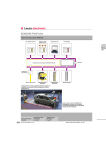
High Level Input Wiring
The high level input(s) should only be used when your head unit lacks RCA outputs.
If the RCA outputs are not present, connect the speaker outputs from the receiver
to the high level input connector of the amplifier. Be sure to observe polarity to
avoid audio phase problems.
NOTE: Do not connect BOTH the high level and low level inputs from your
receiver to your amplifier at the same time!
2-Channel Amplifiers
CXX502, CXX1002, CXX1602, CXX2002, and CXX2502
Remote
Subwoofer Control
INPUT
LEVEL
BASS
BOOST
130
.~~: ..
M~X ~..
LOW PASS
FREQ, Hz
TWO CHANNEL MOSFET POWER AMPLIFIER
L+
L- R-
R+
101
11
DDDDDD
To Speaker Terminals
of head unit
4-Channel Amplifiers
Remote
Subwoofer Control
CXX1204, CXX1604, CXX2004 and CXX2404
101
I
CJCJCJCJCJCJ
I
CH
CH
CH
3+
3-
4- 4+
CH
To Speaker
Terminals
of head unit
CHAOS EXXTREME II MOSFET Amplifier User's Manual- page 9
High Level Input Wiring
The high level input(s) should only be used when your head unit lacks RCA outputs.
If the RCA outputs are not present, connect the speaker outputs from the receiver
to the high level input connector of the amplifier. Be sure to observe polarity to
avoid audio phase problems.
NOTE: Do not connect BOTH the high level and low level inputs from your
receiver to your amplifier at the same time!
5-Channel Amplifier
CXX2705
CH1 +
CH1- CH2- CH2+
Remote
Subwoofer Control
1o1
11
DDDDDD
To Speaker Terminals
of head unit
CH3+ CH3- CH4- CH4+
101
11
DDDDDD
To Speaker Terminals
of head unit
CHAOS EXXTREME II MOSFET Amplifier User's Manual - page 10
High Level Input Wiring
The high level input(s) should only be used when your head unit lacks RCA outputs.
If the RCA outputs are not present, connect the speaker outputs from the receiver
to the high level input connector of the amplifier. Be sure to observe polarity to
avoid audio phase problems.
NOTE: Do not connect BOTH the high level and low level inputs from your
receiver to your amplifier at the same time!
MonoBiock Amplifier
CXXM1250
LOW PASS
FREQUENCY
SENSITIVITY
LEVEL
~D J @. Lo~'••s~l @.
0
35Hz
+18dB
BASS BOOST
160Hz
FULLRANGE
MIN
MAX
w 0
2- 8V
1DOmV- 2V
INPUT CONTROLS
CROSS OVER
@
0
MOSFET MONOBLOCK POWER AMPLIFIER
L+
To Speaker Terminals
of head unit
101
L-
R- R+
I I
DODD DO
MonoBiock Amplifiers
CXXM 1800,CXXM2200
INPUT
LEVEL
BASS
BOOST
CROSSOVER
FREQUENCY
MOSFET MONOBLOCK POWER AMPLIFIER
lol
L+
To Speaker Terminal_s
Of head Unit
L-
R- R+
I
Remote
Subwoofer Control
DDDDDD
CHAOS EXXTREME II MOSFET Amplifier User's Manual - page 11
Power and Speaker Wiring
2-Channel Amplifiers
CXX502, CXX1002, CXX1602,
CXX2002, and CXX2502
~--------------~+
RIGHT
Speaker
Two
Channel
Mode
LEFT
Speaker
SPEAKER
IMPEDANCE
2-80
FUSES
TWO CHANNEL MOSFET POWER AMPLIFIER
_Chassis
ground
point
to REMOTE TURN-ON
terminal of head unit
............._-++_
FUSE
Subwoofer
Bridged
Mode
0CJ
I
CJ
Battery
I
SPEAKER
IMPEDANCE
4-8 Q
FUSES
TWO CHANNEL MOSFET POWER AMPLIFIER
Chassis
ground
point
Connect the Positive (+) terminal of the
subwoofer to the L (+)amplifier terminal.
to REMOTE TURN-ON
terminal of head unit
Connect the Negative(-) terminal of the
subwoofer to the R (-) amplifier terminal.
0CJ
FUSE
CHAOS EXXTREME II MOSFET Amplifier User's Manual - page 12
I
CJ
Battery
I
Power and Speaker Wiring
4-Channel Amplifiers
CXX1204,CXX1604,CXX2004 and CXX2404
CH2
SPEAKER
IMPEDANCE
2-8 Q
Speaker
CH1
Speaker
Four
Channel
Mode
ER AMPLIFIER
_ _ Chassis
ground
point
SPEAKER
IMPEDANCE
2-80
to REMOTE TURN-ON
terminal of head unit
0CJ
FUSE
I
CJ
Battery
I
SPEAKER
IMPEDANCE
4-80
Connect the Negative (-) terminal of the LEFT sub woofer to
the CH2 (-) amplifier terminal.
LEFT
Sub woofer
Connect the Positive(+) terminal of the LEFT subwoofer to
the CH1 (+)amplifier terminal.
Bridged
Mode
Chassis
ground
point
RIGHT
Subwoofer
to REMOTE TURN-ON
terminal of head unit
SPEAKER
IMPEDANCE
4-80
Connect the Negative(-)
terminal of the RIGHT
subwoofer to the CH4 (-)
amplifier terminal.
0
CJ
FUSE
I
CJ
Battery
Connect the Positive(+)
terminal of the RIGHT
subwoofer to the CH3 (+)
amplifier terminal.
CHAOS EXXTREME II MOSFET Amplifier User's Manual - page 13
Power and Speaker Wiring
Five
Channel
Mode
CH5
Subwoofer
5-Channel Amplifier
CXX2705
CH1
~--------------~+
Speaker
SPEAKER
IMPEDANCE
CH2
Speaker
SPEAKER
IMPEDANCE
2-8 0
2-8 0
FIVE CHANNEL MOSFET POWER AMPLIFI R
SPEAKER
IMPEDANCE
2-80
CH3
to REMOTE TURN-ON
terminal of head unit
Speaker
CH4
0Cl
+~------
Speaker
Cl
Battery
Connect the Negative (-) terminal of the LEFT
subwoofer to the CH2 (-) amplifier terminal.
CHS
Subwoofer
Connect the Positive(+) terminal of the LEFT
subwoofer to the CH1 (+)amplifier terminal.
SPEAKER
IMPEDANCE
~------------~+
2-80
I
FUSE
LEFT
Subwoofer
SPEAKER
IMPEDANCE
4-8 0
Bridged
Mode
CH 3/4 BRIDGED
FIVE CHANNEL MOSFET POWER AMPLIFI
to REMOTE TURN-ON
SPEAKER
IMPEDANCE
terminal of head unit
RIGHT
0Cl
Subwoofer
4-8 0
FUSE
I
Cl
Battery
I
Connect the Negative(-) terminal of the RIGHT
subwoofer to the CH4 (-) amplifier terminal.
Connect the Positive(+) terminal of the RIGHT
subwoofer to the CH3 (+)amplifier terminal.
CHAOS EXXTREME II MOSFET Amplifier User's Manual- page 14
Power and Speaker Wiring
Monoblock Amplifiers
CXXM1250 CXXM1800 and CXXM2200
~--------------~+
Speaker
SPEAKER
IMPEDANCE
2-8 Q
MonoBiock
Mode
FUSES
MOSFET MONOBLOCK POWER AMPLIFIER
_Chassis
-:- ground
point
to REMOTE TURN-ON
terminal of head unit
0D
FUSE
I
D
Battery
I
CHAOS EXXTREME II MOSFET Amplifier User's Manual- page 15
Troubleshooting
If you experience operation or performance problems with this product, compare your
installation with the electrical wiring diagram on the previous pages. If problems persist,
read the following troubleshooting tips which may help eliminate the problems.
SYMPTOM
Amplifier will not
power up.
POSSIBLE REMEDY
Check to make sure you have a good ground connection.
Check that the Remote Input (Turn-On) has at least 3VDC.
Check that there is battery power on the(+) terminal.
Check that there is at least 12v.
Check all fuses, replace if necessary.
Make sure that the Protection LED is not illuminated. If it is lit, shut off
the amplifier briefly, and then repower it.
Protection LED
comes on when
amplifier is
powered up.
Remove speaker leads, and reset the amplifier. If the Protection LED still
comes on, then the amplifier is faulty and needs servicing.
No output.
Check that all fuses are OK.
Check for short circuits on speaker leads.
Turn down the volume control on the head unit to prevent overdriving.
Check that amplifier is properly grounded.
Check that the Remote Input (Turn-On) has at least 3VDC.
Check that the RCA audio cables are plugged into the proper inputs.
Check all speaker wiring.
Low output.
Reset the Level Control.
Check the Crossover Control settings.
Audio present in
only one channel.
Check the RCA interconnect cables.
High hiss in the
speakers.
Disconnect all RCA inputs to the amplifiers. If the hiss disappears, then
plug in the component driving the amplifier and unplug its inputs. If the
hiss disappears at this point, go on until the faulty/noisy component is
found.
It is best to set the amplifierls input level control as low as possible. The
best subjective signal-to-noise ratio is achieved in this manner. Try to set
the head unit as high as possible (without distortion) and the amp input
level as low as possible.
Squealing noise
from speakers.
Check for improperly grounded RCA interconnects.
Distorted sound.
Check that the Input Level Control is set to match the signal/eve/ of the
head unit. Always try to set the Input Level as low as possible.
Check all speaker wiring.
Check that all crossover frequencies are properly set.
Check for short circuits on the speaker leads.
Amplifier gets
very hot.
Check that the minimum speaker impedance for the amp model is correct.
Check that there is good air circulation around the amp. In some
applications, it may be necessary to add external cooling fan(s).
Engine noise
(static type)
This is usually caused by poor quality RCA cables, which can pick up
radiated noise. Use only the best quality cables, and route them away
from power cables.
Engine noise
{alternator
whine)
Check that speaker leads are not shorted to the vehicle chassis.
Check that the RCA grounds are not shorted to the vehicle chassis.
Check that the head unit is properly grounded.
CHAOS EXXTREME II MOSFET Amplifier User's Manual- page 16
IO~S
Specifications
AUDIO SYSTEMS
2-Channe/ MOSFET Amplifiers
MODEL
CXX502
CXX1002
CXX1602
CXX2002
CXX2502
RMSPower
into 40
100 W X 2
175 W X 2
240 Wx 2
300 W X 2
500 W X 2
MAX Power
into 2 0
Bridged Power
into 4 0
250Wx 2
500 W X 2
800 W X 2
1000 W X 2
1250W X2
500 W X 1
1000 W X 1
1600 W X 1
2000 W X 1
2500 W X 1
Min. Speaker
Impedance
2 0 Stereo
4 0 Mono Bridged
THD+N
:s;0.01%
25Ax2
30Ax2
40Ax2
13. 78"(L)
15.75"(L)
19.69"(L)
Frequency Response 9Hz- 50 KHz
5/N Ratio
103dB
Channel Separation 90dB
Low Pass Filter
35Hz-160Hz
High Pass Filter
Fixed, 80Hz
Bass Boost
Variable 0 -
Fuse Rating
30A
+ 18 dB
40A
12.20" (L)
Dimensions (Length) : 8.27"(L)
(W X H)(11.00" X 2.87")
MODEL
CXX1204 CXX1604 CXX2004 CXX2404
RMS Power
100 W X 4
into 4 0
MAX Power
150 W X4
MonoBiock
MOSFET
Amplifiers
S-Channe/
MOSFET
Amplifier
4-Channel
MOSFET Amplifiers
200 W x4
300 W x4
CXX2705
CXXM1250 CXXM1800 CXXM2200
150 W X 4 + 500 W X 1
600 W X 1
into20
300W X 4 400W X 4 500W X4 600W X 4 450Wx4 + 1250W X1
900 W X 1
Bridged Power
600W X 2 800Wx2 1000 W X 2 1200 W X 2 600 W X 2
2 0 Stereo
4 0 Mono Bridged
THD+N
:s;0.01%
2200 W X 1
n/a
n/a
20
20
20
9 Hz -130 Hz 9 Hz - 130 Hz
103 dB
n/a
Channel Separation 90dB
Low Pass Filter
1800W X 1
n/a
Frequency Response 9 Hz- 50 KHz
5/N Ratio
900 W X 1
+(600W@40
or 900W@ 20)
into 4 0
Min. Speaker
Impedance
700 W X 1
35Hz-160Hz
High Pass Filter
Fixed, 80Hz
Bass Boost
Variable 0 - + 18 dB
Switchable 0 I+ 18 dB
n/a
n/a
n/a
n/a
30A
25Ax2
30Ax2
1 0.63"(L)
13.78"(L)
16.93"(L)
30Ax 3
30Ax3
35Ax2
25Ax 2 30Ax2
Fuse Rating
Dimensions (Length) : 12.99" (L} 13.78"(L} 16.93"(L) 23.23"(L) 20.28" (L)
(W X H) (11.00" X 2.87"")
n/a
n/a
0- +12dB
4CH/5CH
n/a
n/a
0- +12dB
0/+18dB
n/a
n/a
40Hz-130Hz 40Hz-130Hz
45Hz-90Hz
0/+18dB
Input Mode Selector n/a
n/a
All specifications subject to change without notice.
CHAOS EXXTREME II MOSFET Amplifier User's Manual - page 17
IO~S
AUDIO SYSTEMS
F 0 R
POWER
AMPLIFIERS
THIS CERTIFICATE EXTENDS BOSS AUDIO SYSTEM'S ONE YEAR
ORIGINAL FACTORY WARRANTY TO A TOTAL OF SIX YEARS ON
THIS AMPLIFIER WHEN INSTALLED BY AN AUTHORIZED BOSS
AUDIO SYSTEMS DEALER. THE ADDITIONAL FIVE YEAR WARRANTY
PERIOD COVERS PARTS AND LABOR. ALL OTHER CONDITIONS OF THE
ORIGINAL WARRANTY APPLY.
PLEASE RETAIN YOUR DATED PURCHASE RECEIPT TO VALIDATE THIS
WARRANTY. IF YOU SHOULD NEED TO RETURN ANY BOSS AUDIO
SYSTEMS PRODUCT TO THE FACTORY FOR SERVICE, PLEASE INCLUDE
A CHECK OR MONEY ORDER (MADE PAYABLE TO BOSS AUDIO
SYSTEMS) FOR $20.00 PER PRODUCT RETURNED IN THE CONTINENTAL
U.S. AND $35.00 PER PRODUCT RETURNED FROM HAWAII, ALASKA,
CANADA AND PUERTO RICO TO COVER RETURN SHIPPING AND
HANDLING.
PLACE
POSTAGE
HERE
:IO~S
AUDIO SYSTEMS
THIS PRODUCT IS WARRANTED FOR A PERIOD OF ONE YEAR FROM THE DATE OF PURCHASE AGAINST
DEFECTS IN MATERIALS AND WORKMANSHIP. THE WARRANTY IS FOR REPAIR OR REPLACEMENT AT THE SOLE
DISCRETION OF THE SELLING DEALER. IF WE CHOOSE TO REPLACE YOUR PRODUCT, WE MAY REPLACE IT WITH
A NEW OR RECONDITIONED ONE OF THE SAME OR SIMILAR DESIGN. CUSTOMER WILL BE RESPONSIBLE FOR
FREIGHT CHARGES INCURRED TO RETURN THE PRODUCT AND WILL INCLUDE A CASHIER'S CHECK OR MONEY
ORDER IN THE AMOUNT OF $20.00 FOR CONTINENTAL U.S. OR $35 FOR HAWAII, ALASKA, CANADA AND
PUERTO RICO, PAYABLE TO BOSS AUDIO SYSTEMS TO COVER RETURN SHIPPING AND HANDLING. YOU MUST
SEND A COPY OF THE ORIGINAL INVOICE WITH DATE OF PURCHASE. PLEASE ENCLOSE A LETTER STATING THE
PROBLEM YOU ARE HAVING WITH THE PRODUCT, YOUR DAYTIME PHONE NUMBER, AND YOUR RETURN
SHIPPING ADDRESS (NO P.O. BOXES, PLEASE). PLEASE CONTACT US TO RECEIVE A RETURN AUTHORIZATION
NUMBER (RA#) BEFORE SENDING YOUR DEFECTIVE ITEM.
THIS WARRANTY DOES NOT COVER ANY UNIT SUBJECTED TO ABUSE, NEGLECT, INCORRECT WIRING, WATER
DAMAGE, OR ANY REPAIR OR MODIFICATION PERFORMED BY SOMEONE OTHER THAN A BOSS AUDIO SYSTEMS
REPAIR TECHNICIAN. ANY DAMAGES RESULTING FROM LEGAL ACTION FOR BREACH OF EXPRESSED OR IMPLIED
WARRANTIES SHALL BE LIMITED TO THE COST OF THE ORIGINAL PURCHASE PRICE OF THE UNIT. AS A
CONDITION OF THIS WARRANTY, IT IS AGREED THAT THE REMEDY PROVIDED IN THIS DOCUMENT IS THE SOLE
REMEDY UNDER THIS WARRANTY. ALL LIABILITY FOR COINCIDENTAL DAMAGES IS EXCLUDED. THE PURCHASER
AGREES TO RETAIN THE ORIGINAL PROOF-OF-PURCHASE FOR ESTABLISHING THE EFFECTIVE DATE OF THIS
WARRANTY. SHOULD BOSS AUDIO SYSTEMS OR AN AUTHORIZED DEALER REPLACE YOUR PRODUCT UNDER
WARRANTY, THIS REPLACEMENT SHALL BE CONSIDERED A TRANSACTION UNDER THE ORIGINAL WARRANTY,
AND DOES NOT EXTEND THE ORIGINAL WARRANTY PERIOD. THIS WARRANTY IS NON-TRANSFERABLE.
PLEASE FILL IN THE INFORMATION REQUESTED AND MAIL THIS CARD
TO THE ADDRESS ON THE REVERSE SIDE.
NAME
AGE
ADDRESS
CITY
STATE
BOSS AUDIO DEALER NAME
VEHICLE INFORMATION
WHO INSTALLED THE SYSTEM?
TOTAL COST OF AUDIO SYSTEM?
DATE OF PURCHASE
SERIAL NUMBER
ZIP
USER'S MANUAL
MANUAL DEL USUARIO
CXX12
12" (305mm) 4 0 SUBWOOFER
12" (305mm) 4 0 DE SUBWOOFER
iiO~S
AUDIO SYSTEMS
B()~S
AUDIO SYSTEMS
Congratulations on your purchase of the Boss Audio "CER" Series
Subwoofer. Boss Audio takes great pride in producing products that
Look great, sound great, and stand up to the daily rigors applied by
audio enthusiasts around the world.
1
!10~5
AUDIO SYSTEMS
il\)~5
AUDIO SYSTEMS
CXX12 12"(30.5cm)Subwoofer
• Single 4D Voice Coil
• 1000 W Peak Power Handling
• Polypropylene Cone
• Rubber Surround
BO~~
AUDIO SYSTEMS
2
EIQ~~
AUDIO SYSTEMS
Product Specifications
Impedance
Resonant Frequency
Qts
Qms
Qes
Vas
X max
Sensitivity(1 W/1 m)
Peak Power Handling
Mounting Depth
Cutout Diameter
3
40
32Hz
0.61
2.24
0.83
3.768 cu ft. (106.71iters)
9mm
85 dB
1000 w
4-7/8(124mm)
11-1/32 (280 mm)
510~5
AUDIO SYSTEMS
·AUDIO
ao~s
SYSTEMS
Wiring your Subwoofer
40
II
Multiple Subwoofers
Parallel
Series
20
80
i
:IO~S
AUDIO SYSTEMS
4
510~5
AUDIO SYSTEMS
Enclosures
The CXX12 is designed to work in a medium sized sealed or ported
enclosure . Since the woofer has pole-vent, it needs a minimum
clearance from the rear wall of the enclosure of 0.75 (19 mm). Below you will find the dimensions to make the enclosure to suit the
subwoofers needs, it has been designed for maximum output while
retaining great sound quality.
The dimensions have already accounted for the volume displacement
of the subwoofer, and using 3/4 (19mm) MDF. All dimensions are
external.
Enclosure Dimensions
H
Sealed Dimensions:
Ported Dimensions:
Length(L): 18 (457. 2mm)
Width(W): 12 (304.8mm)
Height(H): 13 (330.2mm)
Cutout Diameter: 11-1/32 (280mm)
Length(L): 24 (609.6mm)
Width(W): 12 (304.8mm)
Height(H): 14 (355.6mm)
Port Diameter: 4 (1 01.6mm)
Port Length: 12 (304.8mm)
Port Freq: 34Hz
Cutout Diameter: 11-1/32 (280mm)
5
510~5
AUDIO SYSTEMS
B()~~
AUDIO SYSTEMS
Technical Support
If you need technical support with your Boss Audio product or have
questions about its use, please contact us:
805.751.4853
www.BossAudio.com
Due to ongoing product development, specifications are subject to change without notice.
B0~5
AUDIO SYSTEMS
6
PLACE
POSTAGE
HERE
THIS PRODUCT IS WARRANTED FOR A PERIOD OF ONE YEAR FROM THE DATE OF PURCHASE AGAINST DEFECTS IN MATERIALS
AND WORKMANSHIP THE WARRANTY IS FOR REPAIR OR REPLACEMENT AT THE SOLE DISCRETION OF SELLING DEALER. IF WE
CHOOSE TO REPLACE YOUR PRODUCT, WE MAY REPLACE IT WITH A NEW OR RECONDITIONED ONE OF THE SAME OR SIMILAR
DESIGN. CUSTOMER WILL BE RESPONSIBLE FOR FREIGHT CHARGES INCURRED TO RETURN THE PRODUCT AND WILL INCLUDE A
CASHIER'S CHECK OR MONEY ORDER IN THE AMOUNT OF $20.00 FOR CONTINENTAL U.S. OR $35.00 FOR HAWAII, ALASKA,
CANADA AND PUERTO RICO, PAYABLE TO BOSS AUDIO SYSTEMS TO COVER RETURN SHIPPING AND HANDLING. YOU MUST
SEND A COPY OF THE ORIGINAL INVOICE WITH DATE OF PURCHASE. PLEASE ENCLOSE A LETTER STATING THE PROBLEM YOU ARE
HAVING WITH THE PRODUCT, YOUR DAYTIME PHONE NUMBER, AND YOUR RETURN SHIPPING ADDRESS (NO PO. BOXES, PLEASE).
PLEASE CONTACT US TO RECEIVE A RETURN AUTHORIZATION NUMBER (RA#) BEFORE SENDING YOUR DEFECTIVE ITEM.
THIS WARRANTY DOES NOT COVER ANY UNIT SUBJECT TO ABUSE, NEGLECT, INCORRECT WIRING, WATER DAMAGE, OR ANY
REPAIR OR MODIFICATION PERFORMED BY SOMEONE OTHER THAN A BOSS AUDIO SYSTEMS REPAIR TECHNICIAN. ANY DAMAGES
RESULTING FROM LEGAL ACTION FOR BREACH OF EXPRESSED OR IMPLIED WARRANTIES SHALL BE LIMITED TO THE COST OF THE
ORIGINAL PURCHASE PRICE OF THE UNIT AS A CONDITION OF THIS WARRANTY, IT IS AGREED THAT THE REMEDY PROVIDED IN
THIS DOCUMENT IS THE SOLE REMEDY UNDER THIS WARRANTY. ALL LIABILITY FOR COINCIDENTAL DAMAGES IS EXCLUDED. THE
PURCHASER AGREES TO RETAIN THE ORIGINAL PROOF-OF-PURCHASE FOR ESTABLISHING THE EFFECTIVE DATE OF THIS
WARRANTY. SHOULD BOSS AUDIO SYSTEMS OR AN AUTHORIZED DEALER REPLACE YOUR PRODUCT UNDER WARRANTY, THIS
REPLACEMENT SHALL BE CONSIDERED A TRANSACTION UNDER THE ORIGINAL WARRANTY, AND DOES NOT EXTEND THE
ORIGINAL WARRANTY PERIOD. THIS WARRANTY IS NON-TRANSFERABLE.
PLEASE FILL IN THE INFORMATION REQUESTED AND MAIL THIS CARD
TO THE ADDRESS ON THE REVERSE SIDE.
NAME
AGE
ADDRESS
CITY
STATE
BOSS AUDIO DEALER NAME
VEHICLE INFORMATION
WHO INSTALLED THE SYSTEM?
TOTAL COST OF AUDIO SYSTEM
DATE OF PURCHASE
SERIAL NUMBER
MODEL NUMBER
ZIP
Boss Audio Systems Free Extended Warranty Program When you purchase directly from BossAudio.com, one of our “Authorized Platinum Online Dealers” or have your product installed at an authorized Boss Audio dealer at the time of purchase, you qualify a free extended warranty on the product you purchased as shown below. Mobile Video & CD and DVD Receivers: 3 Years Total Boss Audio will extend the warranty for an additional two years, 3 years total, directly to the original consumer. Woofers, Speakers, ATV/UTV and Motorcycle Sound Systems: 3 Years Total Boss Audio will extend the warranty for an additional two years, 3 years total, directly to the original consumer. Amplifiers: 6 Years Total Boss Audio will extend the warranty for an additional five years, 6 years total, directly to the original consumer. Other Electronics and Accessories: There is No extended warranty available. Terms and Conditions: Purchases made online from dealers other than Bossaudio.com or an Authorized Platinum Online Dealer listed on this site do not qualify for the free extended warranty program. The online extended warranty program cannot be combined with the Installation Extended Warranty program. The extended warranty is valid only on purchases made and shipped within the US and covers parts and labor to repair only. This program is effective as of 3/1/2015. Any purchase made prior to this date will not qualify for this program. All other conditions of original warranty apply. To see a list of Authorized Platinum online Dealers, please click here. To get service on any product that falls under the Extended Warranty (800)999‐1236 ext. 2239 or email to: http://bossaudio.com/support/, an original or copy of dated purchase receipt is required to validate the warranty and a statement of the problem with the product is needed.