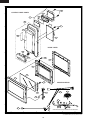
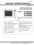
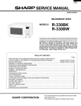
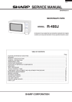
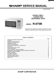
1
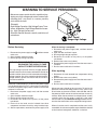
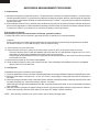
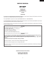
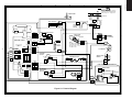
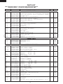
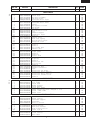
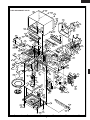
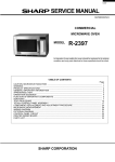
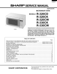
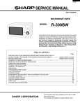
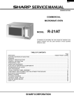
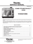
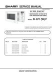
R-820BC
SUPPLEMENTAL SERVICE MANUAL
S2401R820BPW/
DOUBLE GRILL
CONVECTION
MICROWAVE OVEN
MODEL
R-820BC
In the interest of user-safety the oven should be restored to its original
condition and only parts identical to those specified should be used.
GRILL
WARNING TO SERVICE PERSONNEL: Microwave ovens contain circuitry capable of producing very high voltage and
current, contact with following parts may result in a severe,
possibly fatal, electrical shock. (High Voltage Capacitor, High
Voltage Power Transformer, Magnetron, High Voltage Rectifier Assembly, High Voltage Harness etc..)
2 CONVECTIO
N
This is a supplemental Service Manual for Model R-820BC. This model is quite similar to base model R-820BW. Use
this supplemental manual together with the Base Model Service Manual (Refer No. is S5812R820BPW/) for complete
operation, service information, etc..
TABLE OF CONTENTS
Page
PRECAUTIONS TO BE OBSERVED BEFORE AND DURING SERVICING TO
AVOID POSSIBLE EXPOSURE TO EXCESSIVE MICROWAVE ENERGY ................... INSIDE FRONT COVER
BEFORE SERVICING ...................................................................................................... INSIDE FRONT COVER
WARNING TO SERVICE PERSONNEL ................................................................................................................ 1
MICROWAVE MEASUREMENT PROCEDURE ................................................................................................... 2
FOREWORD AND WARNING ............................................................................................................................... 3
PICTORIAL DIAGRAM .......................................................................................................................................... 4
POWER UNIT CIRCUIT ........................................................................................................................................ 5
PARTS LIST .......................................................................................................................................................... 6
PACKING AND ACCESSORIES ........................................................................................................................... 8
SHARP CORPORATION
This document has been published to be used for after
sales service only.
The contents are subject to change without notice.
R-820BC
PRECAUTIONS TO BE OBSERVED BEFORE AND
DURING SERVICING TO AVOID POSSIBLE
EXPOSURE TO EXCESSIVE MICROWAVE ENERGY
(a) Do not operate or allow the oven to be operated with the door open.
(b) Make the following safety checks on all ovens to be serviced before activating the magnetron or other
microwave source, and make repairs as necessary: (1) interlock operation, (2) proper door closing, (3)
seal and sealing surfaces (arcing, wear, and other damage), (4) damage to or loosening of hinges and
latches, (5) evidence of dropping or abuse.
(c) Before turning on microwave power for any service test or inspection within the microwave generating
compartments, check the magnetron, wave guide or transmission line, and cavity for proper alignment,
integrity, and connections.
(d) Any defective or misadjusted components in the interlock, monitor, door seal, and microwave
generation and transmission systems shall be repaired, replaced, or adjusted by procedures described
in this manual before the oven is released to the owner.
(e) A microwave leakage check to verify compliance with the Federal Performance Standard should be
performed on each oven prior to release to the owner.
BEFORE SERVICING
Before servicing an operative unit, perform a microwave emission check as per the Microwave
Measurement Procedure outlined in this service manual.
If microwave emissions level is in excess of the specified limit, contact SHARP ELECTRONICS
CORPORATION immediately @1-800-237-4277.
If the unit operates with the door open, service person should 1) tell the user not to operate the oven
and 2) contact SHARP ELECTRONICS CORPORATION and Food and Drug Administration's
Center for Devices and Radiological Health immediately.
Service personnel should inform SHARP ELECTRONICS CORPORATION of any certified unit found
with emissions in excess of 4mW/cm2. The owner of the unit should be instructed not to use the unit
until the oven has been brought into compliance.
R-820BC
WARNING TO SERVICE PERSONNEL
Microwave ovens contain circuitry capable of producing very high voltage and current, contact with
following parts may result in a severe, possibly
fatal, electrical shock.
(Example)
High Voltage Capacitor, High Voltage Power Transformer, Magnetron, High Voltage Rectifier Assembly, High Voltage Harness etc..
Read the Service Manual carefully and follow all
instructions.
Don't Touch !
Danger High Voltage
When the testing is completed,
1. Disconnect the power supply cord, and then remove
outer case.
2. Open the door and block it open.
3. Discharge high voltage capacitor.
4. Reconnect the leads to the primary of the power
transformer.
5. Reinstall the outer case (cabinet).
6. Reconnect the power supply cord after the outer case is
installed.
7. Run the oven and check all functions.
Before Servicing
1. Disconnect the power supply cord,
outer case.
2. Open the door and block it open.
3. Discharge high voltage capacitor.
and then remove
WARNING:RISK OF ELECTRIC SHOCK.
DISCHARGE THE HIGH-VOLTAGE
CAPACITOR BEFORE SERVICING.
The high-voltage capacitor remains charged about 60
seconds after the oven has been switched off. Wait for 60
seconds and then short-circuit the connection of the highvoltage capacitor (that is the connecting lead of the highvoltage rectifier) against the chassis with the use of an
insulated screwdriver.
After repairing
1. Reconnect all leads removed from components during
testing.
2. Reinstall the outer case (cabinet).
3. Reconnect the power supply cord after the outer case is
installed.
4. Run the oven and check all functions.
Whenever troubleshooting is performed the power supply
must be disconnected. It may in, some cases, be necessary
to connect the power supply after the outer case has been
removed, in this event,
1. Disconnect the power supply cord, and then remove
outer case.
2. Open the door and block it open.
3. Discharge high voltage capacitor.
4. Disconnect the leads to the primary of the power
transformer.
5. Ensure that the leads remain isolated from other
components and oven chassis by using insulation tape.
6. After that procedure, reconnect the power supply cord.
Microwave ovens should not be run empty. To test for the
presence of microwave energy within a cavity, place a cup
of cold water on the oven turntable, close the door and set
the power to HIGH and set the microwave timer for two (2)
minutes. When the two minutes has elapsed (timer at zero)
carefully check that the water is now hot. If the water
remains cold carry out Before Servicing procedure and reexamine the connections to the component being tested.
When all service work is completed and the oven is fully
assembled, the microwave power output should be checked
and microwave leakage test should be carried out.
1
R-820BC
MICROWAVE MEASUREMENT PROCEDURE
A. Requirements:
1) Microwave leakage limit (Power density limit): The power density of microwave radiation emitted by a microwave oven
should not exceed 1mW/cm2 at any point 5cm or more from the external surface of the oven, measured prior to acquisition
by a purchaser, and thereafter (through the useful life of the oven), 5 mW/cm2 at any point 5cm or more from the external
surface of the oven.
2) Safety interlock switches Primary interlock relay and door sensing switch shall prevent microwave radiation emission in
excess of the requirement as above mentioned, secondary interlock switch shall prevent microwave radiation emission
in excess of 5 mW/cm2 at any point 5cm or more from the external surface of the oven.
B. Preparation for testing:
Before beginning the actual measurement of leakage, proceed as follows:
1) Make sure that the actual instrument is operating normally as specified in its instruction booklet.
Important:
Survey instruments that comply with the requirement for instrumentation as prescribed by the performance standard
for microwave ovens, 21 CFR 1030.10(c)(3)(i), must be used for testing.
2) Place the oven tray in the oven cavity.
3) Place the load of 275±15 ml (9.8 oz) of tap water initially at 20±5˚C (68˚F) in the center of the oven cavity.
The water container shall be a low form of 600 ml (20 oz) beaker with an inside diameter of approx. 8.5 cm (3-1/2 in.)
and made of an electrically nonconductive material such as glass or plastic.
The placing of this standard load in the oven is important not only to protect the oven, but also to insure that any leakage
is measured accurately.
4) Set the cooking control on Full Power Cooking Mode
5) Close the door and select a cook cycle of several minutes. If the water begins to boil before the survey is completed,
replace it with 275 ml of cool water.
C. Leakage test:
Closed-door leakage test (microwave measurement)
1) Grasp the probe of the survey instrument and hold it perpendicular to the gap between the door and the body of the oven.
2) Move the probe slowly, not faster than 1 in./sec. (2.5 cm/sec.) along the gap, watching for the maximum indication on
the meter.
3) Check for leakage at the door screen, sheet metal seams and other accessible positions where the continuity of the metal
has been breached (eg., around the switches, indicator, and vents).
While testing for leakage around the door pull the door away from the front of the oven as far as is permitted by the closed
latch assembly.
4) Measure carefully at the point of highest leakage and make sure that the highest leakage is no greater than 4mW/cm2,
and that the secondary interlock switch does turn the oven OFF before any door movement.
NOTE: After servicing, record data on service invoice and microwave leakage report.
2
R-820BC
SERVICE MANUAL
DOUBLE GRILL
CONVECTION
MICROWAVE OVEN
R-820BC
FOREWORD
This Manual has been prepared to provide Sharp Electronics Corp. Service Personnel with Operation and Service
Information for the SHARP MICROWAVE OVEN, R-820BC.
The model R-820BC is quite similar to base model R-820BW (Refer No. is S5812R820BPW/).
It is recommended that service personnel carefully study the entire text of this manual and the based model's manual so that
they will be qualified to render satisfactory customer service.
Check the interlock switches and the door seal carefully. Special attention should be given to avoid electrical shock and
microwave radiation hazard.
WARNING
Never operate the oven until the following points are ensured.
(A) The door is tightly closed.
(B) The door brackets and hinges are not defective.
(C) The door packing is not damaged.
(D) The door is not deformed or warped.
(E) There is no other visible damage with the oven.
Servicing and repair work must be carried out only by trained service personnel.
DANGER
Certain initial parts are intentionally not grounded and present a risk of electrical shock only during servicing.
Service personnel - Do not contact the following parts while the appliance is energized;
High Voltage Capacitor, Power Transformer, Magnetron, High Voltage Rectifier Assembly, High Voltage
Harness;
If provided, Vent Hood, Fan assembly, Cooling Fan Motor.
All the parts marked “*” on parts list are used at voltages more than 250V.
Removal of the outer wrap gives access to voltage above 250V.
All the parts marked “∆” on parts list may cause undue microwave exposure, by themselves, or when they are damaged,
loosened or removed.
SHARP ELECTRONICS CORPORATION
SHARP PLAZA, MAHWAH,
NEW JERSEY 07430-2135
3
BLK BLK
2
2
CN-C
CONTROL PANEL
CN-D
3
SP1
RY6
DOOR SENSING SWITCH
WHT
N.O.
GRY
COM.
OVEN LAMP
& SOCKET
GRN
WHT
BLUE MARK
CN-B
2 GRY
1 GRN
BLK
WHT
WHT
RED
NOTE:
Hot (RED) wire must be
connected to the terminal
with blue mark on the
oven light socket.
FUSE &
HOLDER
THERMAL
CUT-OUT
125°C(MAG.)
3
3
1
CN-B
2
WHT
WHT
ORG
4
BRN
RY3
FAN MOTOR
BLK
ORG
BLK
ORG
BRN
MONITOR
SWITCH
RY4
RED
N.C.
RED
PRIMARY
RY2 INTERLOCK
RELAY
1
CN-A
5
RY1
RY5
ORG
1 GRY
2
3 ORG
4
5 RED
RED
COM
WHT
HIGH VOLTAGE COMPONENTS
MAGNETRON
SECONDARY
INTERLOCK
SWITCH
N.O.
GRY
TURNTABLE
MOTOR
WHT
BRN
COM.
H.V.WIRE A
H.V.
CAPACITOR
WHT
WHT
WHT
WHT
BLK
WHT
H.V.
RECTIFIER
GRY
RED
BRN
5
5
ORG
CN-A
RED
WHT
WHT
T1
CONVECTION
MOTOR
BOTTOM HEATER
WHT
4
4
RED
ORG
WHT WHT
CN-C
CN-D
3 BLK
2
1 BLK
BLK
ORG
THERMAL
CUT-OUT
(OVEN)
BLK
CN-G
GRN
NEUTRAL
BLK
WHT
POWER SUPPLY
CORD
HOT
EARTH
GRY
1
THERMISTOR
GRILL HEATER
R-820BC
A
B
C
D
E
F
G
H
1
NOTE:
The neutral (WHT) wire must be
connected to the terminal with "N"
mark on the power supply cord.
POWER
TRANSFORMER
H.V. WIRE B
6
6
Figure S-1. Pictorial Diagram
A
B
C
D
E
F
G
H
R-820BC
2
1
4
3
6
5
A
A
Q2 2SB1238
R4 27
D1-4
1N4002
GND
C3
VC
C1
VA
C9
VR
C4
INT
C5
BUZZER
C15
FAN MOTOR
C16
CONVECTION
MOTOR
C6
OVEN LAMP
TURNTABLE
MOTOR
C14
BOTTOM
HEATER
+
B
R3 510 1/2w
R2 510 1/2w
c
C
C2
C4 10µ/35v
–
(J1)
C3 0.1µ/50v
D2
D4
b
+
6
d 1
a
LED
D1
D3
–
4
C10
R5 4.7k
C2 470µ/50v
B
10G471K
8
A1
VRS1
AC120V
60Hz
D6
D5
C1 0.1µ/50v
T1
SP1
C
D12
RY5
FAN MOTOR
R6 3.3k
A3
RY1
D
D7
D
RY6
N.O.
Q3
KRC243M
COM
–
+
OVEN LAMP
TURNTABLE
MOTOR
A5
D11
CONVECTION
MOTOR
C5
10µ/35v
RY4
BOTTOM
HEATER
N.O.
D10
E
E
COM
RY3
C8
TOP
HEATER
TOP
HEATER
D9
N.O.
COM
C11
N.C.
C7
MICRO
C17
OVEN
THERMISTOR
C13
N.C.
C12
DOOR
SWITCH
RY2
F
F
D8
N.O.
MICRO
COM
D3
D1
B2
B1
G
G
DOOR SWITCH
OVEN THERMISTOR
NOTE
: IF NOT SPECIFIED, 1/4w ± 5%
: IF NOT SPECIFIED, 1SS270A
H
H
Figure S-2. Power Unit Circuit
1
2
4
3
5
5
6
R-820BC
PARTS LIST
Note: The parts marked “∆” may cause undue microwave exposure.
The parts marked “*” are used in voltage more than 250V.
REF. NO.
PART NO.
DESCRIPTION
Q'TY
CODE
2
2
1
1
1
1
1
1
1
1
1
1
1
1
1
1
2
1
1
1
1
1
1
1
1
AH
AG
AL
AV
AR
AS
AN
AX
AV
AX
AG
AD
AW
AP
AX
AD
AV
BA
AE
AG
AM
AK
BP
BN
BL
1
1
1
2
AW
BE
AX
AC
1
1
1
2
1
1
1
1
2
4
3
5
1
1
2
1
1
1
1
3
1
1
1
1
1
1
1
1
1
1
1
1
1
BD
AC
AB
AK
AB
AA
AE
AA
AA
AD
AA
AA
AA
AB
AB
AB
AA
AA
AG
AK
AG
AK
AG
AQ
AE
BC
BB
AN
AB
AX
AB
AL
AF
ELECTRIC PARTS
*
*
*
*
∆*
∆*
1- 1
1- 1
1- 2
1- 3
1- 3
1- 3
1- 4
1- 5
1- 5
1- 6
1- 7
1- 7
1- 8
1- 9
1-10
1-11
1-12
1-13
1-14
1-15
1-16
1-17
1-18
1-19
1-19
QSW-MA110WRE0
QSW-MA131WRE0
FFS-BA021WRK0
RMOTDA140WRE0
RMOTDA231WRE0
RMOTDA188WRE0
FH-DZA025WRK0
RC-QZA173WRE0
RC-QZA211WRE0
RMOTEA370WRE0
QFSHDA009WRE0
QFSHDA010WRE0
FACCDA074WRE0
FH-HZA063WRE0
RMOTEA372WRE0
QTANNA017WRW0
RHET-A223WRE0
RHET-A209WRE0
RLMPTA030WRE0
QSOCLA021WRE0
RTHM-A109WRE0
RTHM-A078WRE0
RTRN-A568WRE0
RV-MZA222WRE0
RV-MZA267WRE0
Secondary interlock switch / door sensing switch
Secondary interlock switch / door sensing switch (Interchangeable)
Monitor fuse and monitor switch (V-16G-2C25(R)) assembly
Turntable motor
Turntable motor (Interchangeable)
Turntable motor (Interchangeable)
High voltage rectifier assembly
High voltage capacitor (Interchangeable)
High voltage capacitor
Fan motor
Fuse holder
Fuse holder (Interchangeable)
Power supply cord
Thremistor
Convection motor
Short terminal
Grill heater (Top heater)
Bottom heater
Oven lamp
Oven lamp socket
Thermal cut-out 170 deg.
Thermal cut-out 125 deg.
Power transformer
Magnetron
Magnetron (Interchangeable)
2222-
GCABDA097WRW0
GCABUA886WRPZ
GDAI-A305WRW0
GLEGPA074WRE0
Back plate
Outer case cabinet
Base plate
Leg
DPWBFB795WRK0
QCNCMA234DRE0
QCNCMA275DRE0
FW-VZA238DRE0
QCNCMA410DRE0
RC-KZA087DRE0
VCEAB31HW477M
RC-KZA087DRE0
VCEAB31VW106M
RH-DZA006PRE0
VHD1SS270A/-1
VHD1SS270A/-1
VS2SB1238//-3
VSKRC243M//-3
VRD-B12HF511J
VRD-B12EF270J
VRD-B12EF472J
VRD-B12EF332J
RRLY-A080DRE0
RRLY-A076DRE0
RRLY-A080DRE0
RRLY-A076DRE0
RALM-A014DRE0
RTRNPA124DRE0
RH-VZA032DRE0
DPWBFB794WRK0
DPNLCB893WRKZ
JBTN-B267WRTZ
MSPRCA050WRE0
FUNTKB149WREZ
TCAUAA076WRR0
LHLD-A185WRF0
PSHEPA626WRE0
*************
Power unit
3-pin connector (CN-A)
2-pin connector (CN-B)
9pin wire harness (WH-1, WH-2)
2-pin connector (CN-D)
Capacitor
0.1 uF
50V
Capacitor
470 uF
50V
Capacitor
0.1 uF
50V
Capacitor
10 uF
35V
Diode (1N4002)
Diode (1SS270A)
Diode (1SS270A)
Transistor (2SB1238)
Transistor (KRC243M)
Resistor
510 ohm
1/2W
Resistor
27 ohm
1/4W
Resistor
4.7k ohm
1/4W
Resistor
3.3k ohm
1/4W
Relay (OJ-SH-124LM)
Relay (OMIF-S-124LM)
Relay (OJ-SH-124LM)
Relay (OMIF-S-124LM)
Buzzer (PKM22EPT-THAI)
Transformer
Varistor (10G471K)
CPU unit
Control panel frame with key unit
Open button
Open button spring
Key unit
User caution label
LCD holder
LED sheet
This user caution label has been changed to 3-3-4.
CABINET PARTS
1
2
3
4
CONTROL PANEL PARTS
3- 1
3- 1A
3- 1B
3- 1C
3- 1D
C1
C2
C3
C4-5
D1-4
D5-7
D8-12
Q2
Q3
R2-3
R4
R5
R6
RY1
RY2-4
RY5
RY6
SP1
T1
VRS1
3- 2
3- 3
3- 3-1
3- 3-2
3- 3-3
3- 3-4
3- 4
3- 5
3- 6
6
R-820BC
REF. NO.
3- 7
PART NO.
XEPSD30P08XS0
DESCRIPTION
Screw; 3mm x 8mm
Q'TY
CODE
4
AA
1
1
1
1
1
1
1
1
1
1
1
1
1
1
1
1
1
2
2
1
1
1
1
1
1
1
1
1
1
1
1
2
1
1
1
1
1
1
1
2
1
1
1
1
-AL
BH
AQ
AP
AE
AN
AB
AQ
AF
AM
AF
AG
AN
AW
AM
AF
AF
AM
AF
AH
AC
AC
AG
AS
AP
AZ
AE
BE
AA
AY
AC
AE
AX
AX
AC
AR
AM
AK
AX
AU
AR
AQ
AG
1
1
1
1
1
1
0
6
1
BB
AZ
AN
AF
AC
AV
1
2
1
1
1
1
1
1
1
1
1
1
1
AQ
AG
AK
BB
AB
AM
AG
BB
AF
AB
AC
AC
AL
OVEN PARTS
∆ 4- 1
∆
4- 2
4- 3
4- 4
4- 5
4- 6
4- 7
4- 8
4- 9
4-10
4-11
4-12
4-13
4-14
4-15
4-16
4-17
4-18
4-19
4-20
4-21
4-22
4-23
4-24
4-25
4-26
4-27
4-28
4-29
4-30
4-31
4-32
4-33
4-34
4-35
4-36
4-37
4-38
4-39
4-40
4-41
4-42
4-43
4-44
*************
PHOK-A106WRF0
FDUC-A337WRK0
PCOVPA340WRW0
LANGQA478WRP0
MSPRTA186WRE0
NCPL-A051WRE0
PSPA-A109WRE0
LBNDKA136WRP0
NFANJA041WRE0
PDUC-A697WRF0
GCOVHA388WRW0
GLEGPA071WRF0
LANGFA191WRW0
LANGQA489WRP0
LFLG-A030WREZ
MLEVPA226WRF0
MSPR-A004WRE0
PCOV-A011WRP0
PCOVPA339WRE0
PCUSGA385WRP0
PCUSUA190WRP0
PCUSUA191WRP0
PDUC-A691WRF0
PDUC-A692WRP0
PDUC-A784WRWZ
PGLSPA518WRE0
PPACGA050WRE0
PREFHA061WRW0
PSHEPA487WRE0
PSKR-A331WRP0
MSPRCA113WRE0
PCUSGA420WRP0
NFANMA047WRP0
NFANMA048WRP0
PCUSUA499WRP0
PDUC-A707WRW0
PFPF-A210WRE0
PPIPFA030WRE0
PSKR-A339WRP0
PSKR-A345WRW0
PSKR-A346WRW0
PSLDHA140WRW0
PCUSGA389WRP0
Oven cavity (Not a replaceable part)
Latch hook
Air duct assembly
Sub back plate
Turntable motor angle
Plate spring
Turntable motor shaft
Spacer
HV capacitor holder
Fan blade
Fan duct
Bottom heater cover
Leg
Chassis support
Thermistor angle
Bearing
Switch lever
Heat seal spring
Bottom heater angle
Waveguide cover
Cushion
Cushion
Cushion
Air intake duct
Exhaust duct
Air guide
Light glass
Cushion
Reflector
Heater film
Air separate angle
H-spring
Cushion
Convection fan
Cooling fan
Cushion
Convection duct
Thermal insulation
Pipe
Convection air angle
Convection motor angle A
Convection motor angle B
Convection thermal cover
Cushion
555555555-
1
2
3
4
5
6
7
8
9
DDORFA857WRK0
GWAKPA948WRRZ
LSTPPA176WRF0
LSTPPA177WRF0
MSPRTA187WRE0
PGLSPA513WRE0
*************
XCPSD40P08000
GCOVHA387WRF0
Door panel assembly
Door frame
Latch head
Glass stopper
Latch spring
Front door glass
These screws have been changed to 5-8.
Screw : 4mm x 8mm
Choke cover
6- 1
6- 2
6- 3
6- 4
6- 5
6- 6
6- 7
6- 8
6- 9
6-10
6-11
6-12
6-13
FAMI-A104WRM0
TCAUAA145WRR0
FSRAHA063WRYZ
NTNT-A097WRE0
TCAUAA200WRR0
TINSEB034WRRZ
FW-VZB045WRE0
FW-VZB872WREZ
QW-QZA213WRE0
LHLDWA011WRE0
TCAUAA201WRR0
TCAUAA240WRR0
TLABMA978WRRZ
Rack
Earth caution
Turntable support
Turntable
Monitor caution
Instruction book
Switch harness
Main wire harness
High voltage wire B
Purse lock M
DHHS caution label
Screw caution
Menu label
DOOR PARTS
∆
∆
∆
AA
AS
MISCELLANEOUS
*
7
R-820BC
REF. NO.
6-14
PART NO.
TLABNB032WRRZ
Touch guide
DESCRIPTION
7- 1
7- 2
7- 3
7- 4
7- 5
7- 6
7- 7
7- 8
7- 9
7-10
7-11
7-12
7-13
7-14
7-15
7-16
7-17
7-18
7-19
7-20
XFPSD40P08K00
XEPSD40P25000
LX-EZA042WRE0
LX-NZ0061WRE0
XBPWW30P05K00
XCTWW40P08000
XHPSD30P06000
XHTSD40P08RV0
XOTSD40P12RV0
XOTSD40P12000
*************
XOTSF40P08000
XBTSD40P05000
XNEUW40-32000
XRESE40-06000
XWHUW40-08000
XWHUW48-08120
XWSUW40-10000
LX-CZA070WRE0
XCPSD40P08000
Screw : 4mm x 8mm
Screw : 4mm x 25mm
Special screw
Flange nut
Screw : 3mm x 5mm
Screw : 4mm x 8mm
Screw : 3mm x 6mm
Screw : 4mm x 8mm
Screw : 4mm x 12mm
Screw : 4mm x 12mm
These line head screws have been changed to 7-9.
Screw : 4mm x 8mm
Screw : 4mm x 5mm
Nut : 4mm x 3.2mm
Ring : 4mm x 0.6mm
Washer : 4mm x 0.8mm
Washer : 4.8mm x 0.8mm
Washer : 4mm x 1.0mm
Special screw (Torx tamper proof screw)
Screw : 4mm x 8mm
Q'TY
1
CODE
AK
13
2
2
4
2
8
1
3
13
10
0
1
2
1
1
1
1
1
2
1
AA
AA
AB
AA
AA
AB
AA
AA
AA
AA
-AA
AA
AA
AA
AA
AA
AA
AC
AA
SCREWS,NUTS AND WASHERS
HOW TO ORDER REPLACEMENT PARTS
To have your order filled promptly and correctly, please furnish the following information.
1. MODEL NUMBER
2. REF. NO.
3. PART NO.
4. DESCRIPTION
Order Parts from the authorized SHARP parts Distributor for your area.
Defective parts requiring return should be returned as indicated in the Service Policy.
PACKING AND ACCESSORIES
TOP PAD ASSEMBLY
(FPADBA381WRK0)
WRAP COVER
TRAY HOLDER
(SSAKHA034WRE0)
(SPADFA424WRE0)
PLASTIC SHEET
TURNTABLE TRAY
(SPADPA616WREZ)
RACK
DOOR PROTECTION SHEET
(SPADPA204WRE0)
CABINET COVER
(SPAKHA009WRE0)
LAMP CAUTION
TOUCH GUIDE
INSTRUCTION BOOK
TURNTABLE SUPPORT
BOTTOM PAD ASSEMBLY
FOAM SHEET
TRAY PAD
(FPADBA382WRK0)
(SPAKHA012WREZ)
(SPADPA577WRE0)
PACKING CASE
Not Replaceable Items.
8
FPAK-A505WRKZ
R-820BC
2
1
4
3
6
5
7-9
OVEN AND CABINET PARTS
2-2
7-19
7-9
A
A
6-11
7-9
7-8
2-1
7-19
4-33
6-2
4-4
B
B
7-10
4-25
7-9
7-12
4-29
7-5
4-36
7-10
4-23
4-44
4-3
1-11
4-26
4-41
C
1-12
7-10
7-17
4-27
7-4
7-10
1-16
4-30
D
4-39
1-9
C
4-42
4-38
7-1
1-14
4-18
7-10
1-15
1-8
4-35
4-40
6-13
7-10
7-13
7-10
4-31
4-19
4-32
7-15 1-10
4-15
4-43
7-6
4-34 x3
A
D
7-13
6-12
4-1
7-8
4-37
7-16
7-6
6-5
6-7
7-6
4-24
7-1
4-16
7-1
4-7
4-8
4-20
4-6
1-17
E
4-14
7-10
4-18
4-32
4-21
4-19
4-11
7-4
7-20
4-2
4-5
6-4
A
4-40
7-7
7-9
1-13
E
7-18
7-14
7-8
7-10
7-6
1-5
1-6
7-2
1-4
4-10
1-1
1-3
F
7-1
F
1-7
7-1
7-1
4-12
4-9
7-1
6-3
1-2
4-22
6-2
1-1
7-3
1-18
1-19
4-17
7-1
G
G
4-28
2-3
4-13
7-9
2-4
H
H
7-9
2-4
1
2
7-9
4
3
9
5
6
R-820BC
2
1
4
3
6
5
3-7
CONTROL PANEL PARTS
3-4
A
A
3-5
3-2
3-3
3-7
B
B
3-3-3
3-3-4
3-1
C
C
DOOR PARTS
3-3-1
D
D
5-8
3-3-2
5-9
E
E
5-1
5-6
5-2
F
F
5-8
G
MISCELLANEOUS
6-1
6-7
5-3
5-4
G
5-5
6-8
H
H
6-10
6-9
Actual wire harness may be different from illustration.
1
2
4
3
5
6
2004 SHARP CORP. (2S1.700E) Printed in U.S.A
10