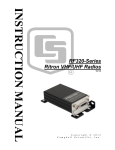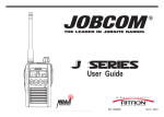
1
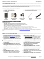
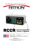
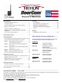
Owner’s Manual
Basic Operation
RDC-SERIES DOORCOM™ MODELS ............................................ i
SYSTEM COMPONENTS ............................................................ 1
OPTIONAL AND REPLACEMENT ACCESSORY EQUIPMENT............... 1
BRIEF FEATURE OVERVIEW ....................................................... 1
CONTROLS, CONNECTORS AND BUTTONS ................................... 2
Figure-1: RDC-1 and R-Series Radio, Controls and
Connectors ............................................................................ 2
INITIAL SET-UP AND PROGRAMMING ........................................... 2
Licensing
FCC Licensing ..................................................................... 13
How to Obtain an FCC Radio License ................................. 13
INDUSTRY CANADA Regulations....................................... 13
INDUSTRY CANADA License Application ........................... 13
Service ................................................................................. 13
Warranty
RITRON, INC. LIMITED WARRANTY ......................................... 14
Programmable Features ......................................................... 3
Field Programming
HOW TO READOUT CURRENT RADIO FREQUENCY & TONE CODES. 4
HOW TO FIELD PROGRAM FREQUENCY & TONE CODES ................ 5
TABLE 1: PROGRAMMABLE FREQUENCY CODES....................... 6
CANADIAN FREQUENCY CODES ................................ 6
TABLE 2: INTERFERENCE ELIMINATOR PROGRAMMABLE QC
TONE CODES ......................................................... 7
TABLE 3: INTERFERENCE ELIMINATOR PROGRAMMABLE DQC
TONE CODES ......................................................... 7
TABLE 4: ADVANCED FEATURE CODES ................................... 7
TABLE 5: SINGLE DIGIT RADIO FEATURE CODES ...................... 8
HOW TO FIELD PROGRAM RADIO FEATURE CODES ...................... 8
Installation Instructions
RDC-1 SPEAKER INTERCOM BOX INSTALLATION INSTRUCTIONS .... 9
Figure -2: RDC-1 INSTALLATION ............................................. 9
R-SERIES RADIO INSTALLATION INSTRUCTIONS ......................... 10
Figure -3: R-Series Radio Installation ................................. 10
RDC-SERIES DOORCOM™ MODELS ........
The radio transceiver’s model number appears on the serial label located on the bottom-side of the metal enclosure.
VHF Models
RDC-146
VHF Wireless Intercom
2 Watts, 150 - 165 MHz
RDC-146M
VHF MURS License-Free,
Wireless Intercom,
2 Watts, 7 MURS Frequencies Only
RDC-146-BC
VHF Wireless Intercom
2 Watts, 150-165MHz
(British Columbia)
RDC-146-Canada
VHF Wireless Intercom
2 Watts, 150-165MHz
UHF MODELS
RDC-446
UHF Wireless Intercom
2 Watts, 450-470MHz
RDC-446-Canada
Operating Instructions
UHF Wireless Intercom
2 Watts, 450-470MHz
OPERATING THE DOORCOM™ WIRELESS INTERCOM ................... 11
EXPOSURE TO RADIO FREQUENCY ENERGY .............................. 12
SAFETY STANDARDS .................................................................. 12
___________________________________________________________________________________________________________
Ritron Publication 14500083
Rev. A 06-12
®
© 2012 Ritron, Inc. All rights reserved. Ritron, Patriot, Jobcom, OutPost, GateGuard, Quick Assist and RadioNexus are registered trademarks of Ritron, Inc.
DoorCom, Quick Talk and Liberty are trademarks of Ritron, Inc.
Call 800-USA-1-USA for the right Wireless Solutions to your communication needs.
P.O. Box 1998 • Carmel, Indiana 46082-1998 • USA
Phone: 317-846-1201; 800-USA-1-USA (800-872-1872) • Fax: 317-846-4978
Email: [email protected] • Website: www.ritron.com
RDC-Series DoorComTM Wireless Intercom
Basic Operation
SYSTEM COMPONENTS .........................................................................
The DoorCom™ Wireless Intercom System provides 2-way, voice communication from delivery doors or other fixed locations to radioequipped personnel in or around the facility. The rugged, all-metal, weather-resistant speaker intercom box can be mounted outdoors
and is connected to the AC powered radio transceiver (indoors) with the 20ft connecting cable.
The DoorCom™ wireless intercom consists of 6 components.
1. The R-Series Radio Transceiver
2. RPS-1B - 110VAC AC Power Adaptor
3. AFB-1545 - BNC Flexible Antenna
4. T-25 TORX bit
R-Series
Transceiver
RDC-1 w/20 ft Cable
PN#60201121
5.
6.
RDC-1, Stainless Steel, Speaker Intercom Box with 20 ft
Connecting Cable attached (connects RDC-1 to radio)
Wall Mount Bracket for radio transceiver
RPS-1B, 110VAC
AC Adapter
AFB-1545
Antenna
Mounting Bracket
OPTIONAL AND REPLACEMENT ACCESSORY EQUIPMENT
Available options include:
•
AFB-1545 – Replacement, Molded Flex, Dual-Band Replacement Antenna
•
RAM - 1545 – Optional, Magnet Mounted, Dual-Band Antenna w/BNC Connector
•
RPS-1B – Replacement, 110VAC to 12VDC Power Supply.
•
JBS-MMK – Replacement, Mobile Mounting Kit.(Does not include screws to mount bracket to the wall)
•
RDC-1 – Replacement, RDC-1, metal speaker intercom box. Includes PN#60201121 20ft cable, connects to radio.
• PN# 60201121 – 20ft Cable (RDC-1 to R-Series Transceiver) 2.5mm/3.5mm plug to spade lugs.
For additional information and pictures of these items go to http://www.ritron.com/doorcom.html and download pdf of the product brochure.
BRIEF FEATURE OVERVIEW ..................................................................
•
License-Free VHF MURS Model. The VHF RDC-146M
model can be programmed from a list of 7 VHF MURS
frequencies. These FCC frequencies are for business-only
use and license-free.
Mode of Operation. The DoorCom™ Wireless Intercom can
operate in one of two possible modes.
o “Automatic Turn-Off” Mode (Factory Default). The radio
and speaker are OFF until the Call Button is pressed.
Radio and speaker remain ON subject to activity on the
channel and the reset timer setting (Default 10 seconds).
o “Intercom” Mode. The radio and speaker are always ON.
•
Licensed VHF and UHF Models. These models contain
table frequencies that require an FCC license. They can also
be PC programmed to “custom” frequencies making the
DoorCom™ system compatible with an existing radio system
or even radio repeaters.
DoorCom™ Time-Out Tone – A double tone alerts the visitor
when the speaker has turned OFF. The same tone is
transmitted to radio-equipped personnel to signal that the
RDC-1 speaker has turned off and internal radio
communication can now continue.
•
Choose From Two Distinct Call Tones – “Door Bell” or
“Ringing Tone”.
•
Interference Eliminator Codes - Quiet Call (QC) and Digital
Quiet Call (DQC) codes can be programmed to eliminate
other radio users not in your workgroup. For compatibility,
new radios must be programmed with the same codes.
•
Manager Lock - Prevents radio controls from being changed
by unauthorized personnel.
DTMF Signaling - 1-9 digit DTMF codes can be transmitted
at the beginning of each message for radio identification.
•
Narrow Band FCC Compliant. The radio is compliant with
the Federal Commuinication Commission’s 2013 Narrow
Band Mandate – go to www.ritron.com for more information.
•
Field-Programming. Field-programming allows you to
program specific features of the radio without a PC or special
software.
•
•
•
Speaker Volume. Field-settable in pre-set levels 0-9.
•
Multi-Channel Pre-Sets – Up to 10 different pre-set
channels
•
Auto-ON When AC Power Applied – If AC power is
removed from the radio i.e. a power failure, the radio will
automatically turn ON, whenever AC power is restored.
•
Have questions? Call 800-USA-1-USA (800-872-1872) or visit our website at www.ritron.com
page 1
RDC-Series DoorComTM Wireless Intercom
Basic Operation
CONTROLS, CONNECTORS & BUTTONS .................................................
1
Multi-Function LED Display
The LED display will indicate the current Operating
Channel, the Speaker Volume setting (0-9), the Manager
Lock condition and Field-Programming Information.
2
Channel Select Button
Press the Channel Button to advance to the next
programmed channel.
3
Speaker Volume-Up/Down Buttons
Press the Volume Up Button to increase the volume, and
press the Volume Down Button to decrease the volume.
The volume level will be displayed momentarily in the
channel display.
4
8
6
7
8
3
1
2
Speaker/Microphone Connection
The RDC-1 Speaker Intercom Box is connected to the
radio here using the 2-PIN Connecting Cable PN#
9
7
60201121.
5
6
5
10
P ow e r C o n n e c t o r
The Power Connector on the top of the radio is used to
connect power to the unit. Use the included 110VAC,
RPS-1B AC Adapter.
B N C An t e n n a
The antenna radiates and receives radio signals. The
included AFB-1545 Antenna connects to the BNC
Connector on the top of the radio.
Radio Program Button
When the radio is in PTT Programming Mode, the
Program Button is used to change channel information.
The channel display will display the programming
information as it is entered.
RDC-1, Rugged, Stainless Steel Intercom Box
Tough, weather-resistant, all-metal enclosure protects
against damage from weather and vandalism. Includes
mutliple mounting options without brackets.
4
11
Figure 1: RDC-1 and R-Series Radio, Controls and Connectors
9
Weather-Resistant Speaker (RDC-1)
Weather-resistant speaker is protected from vandalism by metal
speaker/mic guard. Speaker allows you to hear radio
transmissions on your radio frequency.
10 Weather-Protected Electret Microphone (RDC-1)
Weather-protected mic is also protected from damage by metal
speaker/mic guard. Allows your voice to be heard in
transmissions to other radios.
11 Weather-Proof, Vandal-Resistant PTT Button (RDC-1)
Rugged metal PTT Button protects against damage from
vandals. Press and Hold to talk, release to listen.
INITIAL SET-UP & PROGRAMMING .........................................................
IMPORTANT - BEFORE permanently installing the DoorCom™ wireless intercom, you will need to review how you would like the DoorCom™ to operate. You will then need to temporarily set-up the system and apply power to the radio. This is necessary to program the
radio and then test the system to confirm you have programmed it correctly.
For example:
•
You will need to decide which DoorCom™ radio frequency and interference eliminator codes you intend to use.
•
You will need to decide which of the two possible Modes of Operation you intend to use.
•
You will need to decide where you intend to install the R-Series radio transceiver (INDOOR only mounting).
•
Keep in mind, you will need to provide 110VAC to within a few feet of the radio.
•
You will need to decide where you intend to install the RDC-1 speaker intercom box (INDOOR/OUTDOOR).
•
The RDC-1 to radio connecting cable is 20ft. in length.
•
The location of the antenna will also need to be clear of any metal objects and power lines.
•
Keep clearance at least 3 feet in all directions.
Have questions? Call 800-USA-1-USA (800-872-1872) or visit our website at www.ritron.com
page 2
RDC-Series DoorComTM Wireless Intercom
Programmable Features
PROGRAMMABLE FEATURES ................................................................
Review the features below to determine how your system will
operate. Certain features have been pre-configured as the
Factory Default setting and do not require reprogramming.
Some of the features listed can be Field-Programmed (FP)
without additional tools, and other features require a computer
and programming software (PC). Please call Ritron if you have
any questions or require special programming.
Glossary of Terms
FP = Field-Programmable Feature– no PC & software
required.
PC = PC Programmable Feature with PC & Software
Automatic Turn-Off Mode – Speaker and radio both
automatically turn off after programmable period of inactivity.
Intercom Mode – Automatic Turn-Off feature has been
disabled, the radio is able to receive calls at any time.
Inactivity Time – A continuous period of time where the radio
transceiver is not sending or receiving a call.
1. Field-Programming Enable..................... (PC)
This feature is ENABLED as the Factory Default setting.
If Field-Programming is enabled, the radio can be fieldprogrammed from a list pre-determined Table Frequencies,
Interference Eliminator codes and other FP features.
If DISABLED, all features must be programmed using special
Ritron PC Programming software and a computer.
2. Mode of Operation - A or B ............ (PC or FP)
A) . Au t o m a t i c T u r n - O f f M o d e
Feature is ENABLED as Factory Default setting.
The speaker and the radio will turn OFF when the Reset Time
has expired. The Reset Time is a pre-programmed amount of
time of “inactivity” (no calls transmitted, no calls received)
before the speaker and radio turns off. The speaker and radio
are turned ON when the PTT button is pressed.
B). Intercom Mode
If Automatic Turn-Off is NOT enabled, the speaker and the
radio are always on… i.e. Intercom mode. This mode allows
the speaker to hear radio calls all the time.
3. Send A Call Tone ......................... .(PC or FP)
Feature is ENABLED as Factory Default setting.
Choose from 2 call tones – Door Bell sound (Factory Default)
or Ringing sound.
The radio can be programmed to transmit of the 2 Call Tones
upon the initial press of the PTT button. This will signal radioequipped personnel that the call is originating from the
DoorCom™ wireless intercom.
4. Send DoorCom™ Time-Out Tone . . . . . . . . . . . . . . ( P C o r F P )
Feature is ENABLED as Factory Default setting.
A HI/Low double-tone alerts the visitor that the speaker has
turned OFF. The same tone is transmitted to radio-equipped
personnel to signal that the RDC-1 speaker is now off and
internal radio communication can continue.
5. Manager Lock ................................................................ (FP)
Factory Default setting is: “UNLOCKED”.
When radio controls are “Locked”, the operating channel and
speaker volume settings cannot be changed.
Press the VOL Up AND VOL Dwn buttons simultaneously for 5
seconds. The display will show the current setting:
“U” = Unlocked
“L” = Locked.
Repeat the above step to toggle between “U” and “L” condition.
6 . I n a c t i vi t y R e s e t T i m e . . . . . . . . . . . . . . . . . . . . ( P C o r F P )
Factory Default setting: 10 seconds.
The Reset Time can be Field-Programmed to 9 different times
ranging from 5 seconds to 4 minutes, or PC programmed for
5 to 255 seconds. In Automatic Turn-Off mode a longer Reset
Time will allow more time for a response before the speaker
and the radio turn off.
7. Busy Channel TX Inhibit................ (PC or FP)
Feature is DISABLED as Factory Default setting.
With this feature enabled the radio cannot transmit when there
is a received signal on the frequency. When a received signal
is present and the PTT buton is pressed, a “busy signal” will be
heard in the RDC-1 speaker.
8 . T r a n s m i t B e e p E n a b l e . . . . . . . . . . . . . . . . . . . . . . . . . . . . . ( PC)
Feature is ENABLED as Factory Default setting.
A short beep will sound in the RDC-1 speaker any time the
PTT button is pressed. This indicates to the user that the
intercom is ready to transmit their message.
9 . R X C o u r t e s y B e e p E n a b l e . . . . . . . . . . . . . . . . . . . . . . . . ( PC)
Feature is DISABLED as Factory Default setting.
In high noise environments it is sometimes difficult to
determine when a received message has ended. With the RX
Courtesy Beep enabled the radio will sound a short beep on
the speaker at the end of each received transmission.
1 0 . D T M F AN I . . . . . . . . . . . . . . . . . . . . . . . . . . . . . . . . . . . . . . . . . . . . ( P C )
The radio can be programmed to send a 1-9 digit DTMF ANI
code at the beginning of each transmission. Allows Caller ID in
only those radio systems equipped with DTMF Decode.
11. TX Time Out Time ................................ (PC)
Factory Default setting is 60 seconds.
The TX Time Out Time can be programmed for 1-255 seconds.
This sets the length of time the radio can transmit continuously.
If the PTT button is held down longer then the TX Time Out
Time, the radio will stop transmitting and a “Busy Signal” will
be heard in the speaker until the button is released.
1 2 . C u s t o m F r e q u e n c y P r o g r a m m i n g . . . . . . . . . . . ( PC)
The radio can be PC programmed with Ritron R-Series
software to operate on custom narrow band frequencies within
the radios specific operating band. MURS model cannot be
custom programmed to other frequencies.
Have questions? Call 800-USA-1-USA (800-872-1872) or visit our website at www.ritron.com
page 3
RDC-Series DoorComTM Wireless Intercom
HOW
TO
Field Programming
READOUT CURRENT RADIO FREQUENCY & TONE CODES ..........
1.
Connect the RDC-1 and 20 ft cable to the R-Series radio.
2.
Attach the antenna to the radio.
3.
Locate the RPS-1B AC adapter (do not connect it to the radio yet).
4.
Press and HOLD the Program Button (See Figure 1 on page 2 for location) and now connect power to the radio using the RPS-1B
AC adapter, the radio will now turn ON. A "P" will appear on the program display and the speaker will beep rapidly.
5.
When the beeping stops, release the Program Button. The radio will display a series of six characters for Radio Identification, with
each character separated by a hyphen. The 1st two characters indicate the Model Number, the 3rd and 4th characters indicate the
radio type, and the 5th and 6th characters indicate the firmware revision.
For this example:
MODEL
Model:
Radio Type:
Firmware Revision:
RADIO TYPE
01
31
51
FIRMWARE REVISION
6.
After the Radio Identification has been displayed, the digit 1 will appear, followed by a hyphen and the speaker will sound a triple
beep indicating that the radio is in Program Mode and Channel 1 is selected.
7.
Press the Channel selector to select the channel to be read out. The channel number will appear briefly on the display as you step
through the channels. When you have settled on a channel a hyphen will appear across the center of the display to indicate that it
is ready for readout.
8.
Press and RELEASE the Volume Up Button (See FIG-1 on page 2 for location). The radio will immediately begin to display a
series of four digits; with each digit separated by a hyphen.
9.
The first two digits indicate the frequency code and the last two digits the tone code; see Table 1 and Table 2 on pages 6 and 7.
In this example an R-446 is programmed to operate on the “Brown Dot” frequency of 464.500 MHz (Frequency code “04”) with
100.0 Hz tone (Tone code “12”).
FREQUENCY CODE
TONE CODE
th
10. If a 5 digit is displayed, the channel has been programmed for DQC and the last three digits indicate the DQC code; see Table 3
on page 7. In this example an R-446 was programmed to operate on the “Brown Dot” frequency of 464.500 MHz (Frequency code
“04”) with a DQC code of “723”.
FREQUENCY CODE
DQC CODE
11. If the channel is PC programmed with any frequency or tone not listed in Table 1, Table 2 or Table 3 on pages 6 and 7, the radio
will sound the ERROR TONE on contents read out and display an "E". The PC programmer will be required to readout the radios
frequency and tone programming.
12. To return the radio to normal operation:
1)
2)
Disconnect the AC adapter from the radio.
THEN reconnect the AC adapter to the radio.
Have questions? Call 800-USA-1-USA (800-872-1872) or visit our website at www.ritron.com
page 4
RDC-Series DoorComTM Wireless Intercom
HOW
TO
Field Programming
FIELD PROGRAM FREQUENCY & TONE CODES ..........................
To match other radios, the owner can select Frequency, Tone and DQC Codes from Table 1, Table 2 and Table 3 on pages 6 and 7. In
our example, we will program an R-446 to operate on the "Brown Dot" frequency of 464.500 MHz with 100.0 Hz tone.
04
12
1.
Connect the RDC-1 and 20 ft cable to the R-Series radio.
2.
Attach the antenna to the radio.
3.
Locate the RPS-1B AC adapter (do not connect it to the radio yet).
4.
Refer to Table 1 on page 6 to determine the two-digit frequency code for 464.500 MHz and write it down.
5.
Refer to Table 2 on page 7 to determine the two-digit tone code for 100.0 Hz and write it down.
6.
Press and HOLD the Program Button (See Figure 1 on page 2 for location) and now connect power to the radio
using the RPS-1B AC adapter, the radio will now turn ON. A "P" will appear on the program display and the
speaker will beep rapidly.
7.
When the beeping stops, release the Program Button. The radio will display a series of six characters for Radio
Identification, with each character separated by a hyphen. The 1st two characters indicate the Model Number,
the 3rd and 4th characters indicate the radio type, and the 5th and 6th characters indicate the firmware revision.
For this example:
MODEL
Model:
Radio Type:
Firmware Revision:
RADIO TYPE
01
31
51
FIRMWARE REVISION
8.
After the Radio Identification has been displayed, the digit 1 will appear, followed by a hyphen and the speaker
will sound a triple beep indicating that the radio is in Program Mode and Channel 1 is selected.
9.
Press the Channel selector to select the channel to be programmed. The channel number will appear briefly on
the display as you step through the channels. When you have settled on a channel a hyphen will appear across
the center of the display to indicate that it is ready for programming.
10. Enter the 1st digit of the frequency code by pressing the Program button until the display shows the desired
number. Pause—the speaker will sound a low tone and the radio will show a hyphen across the center of the
display to indicate that it is ready to accept the next digit.
11. Enter the 2nd digit of the frequency code by pressing the Program button until the display shows the desired
number. Pause—the speaker will sound a low tone and the radio will show a hyphen across the center of the
display to indicate that it is ready to accept the next digit.
12. Enter the 1st digit of the tone code (or 1st digit of the DQC code) by pressing the Program button until the display
shows the desired number. Pause—the speaker will sound a low tone and the radio will show a hyphen across
the center of the display to indicate that it is ready to accept the next digit.
13. Enter the 2nd digit of the tone code (or 2nd digit of the DQC code) by pressing the Program button until the display
shows the desired number. Pause—the speaker will sound a low tone and the radio will show a hyphen across
the center of the display to indicate that it is ready to accept the next digit.
rd
14. FOR DQC CODES ONLY – Enter the 3 digit of the DQC code by pressing the Program button until the display
shows the desired number. Pause—the speaker will sound a low tone and the radio will show a hyphen across
the center of the display to indicate that it is ready to accept the next digit.
15. Press and release the Volume Up button to SAVE your programming. A triple beep will sound to indicate that
programming was successful and a hyphen will appear on the program display. The radio is now ready for
another program entry.
NOTE: An error tone will sound if you attempt to save an incorrect code, an "E" will appear on the display.
Check the digits you are attempting to enter, then re-enter.
16. To return the radio to normal operation:
1) Disconnect the AC adapter from the radio.
2) THEN reconnect the AC adapter to the radio.
Have questions? Call 800-USA-1-USA (800-872-1872) or visit our website at www.ritron.com
page 5
RDC-Series DoorComTM Wireless Intercom
Field Programming
TABLE 1: PROGRAMMABLE FREQUENCY CODES .........................................................
UHF Business Band
Code
01
02
03
04
05
06
07
08
09
10
11
12
13
14
15
16
17
18
19
20
21
22
23
24
25
26
27
28
29
30
31
32
33
34
35
36
37
38
39
Frequency
467.7625
467.8125
464.5500
464.5000
467.8500
467.8750
467.9000
467.9250
469.2625
462.5750
462.6250
462.6750
464.3250
464.8250
469.5000
469.5500
463.2625
464.9125
464.6000
464.7000
462.7250
464.5000
464.5500
467.7625
467.8125
467.8500
467.8750
467.9000
467.9250
461.0375
461.0625
461.0875
461.1125
461.1375
461.1625
461.1875
461.2125
461.2375
461.2625
Color Dot
J
K
Yellow Dot
Brown Dot
Silver Star
Gold Star
Red Star
Blue Star
White Dot
Black Dot
Orange Dot
UHF Business Band
BW
12.5
12.5
12.5
12.5
12.5
12.5
12.5
12.5
12.5
12.5
12.5
12.5
12.5
12.5
12.5
12.5
12.5
12.5
12.5
12.5
12.5
12.5
12.5
12.5
12.5
12.5
12.5
12.5
12.5
12.5
12.5
12.5
12.5
12.5
12.5
12.5
12.5
12.5
12.5
Code
40
41
42
43
44
45
46
47
48
49
50
51
52
53
54
55
56
57
58
59
60
61
62
63
64
65
66
67
68
69
70
71
72
73
74
75
76
77
99
Frequency
461.2875
461.3125
461.3375
461.3625
462.7625
462.7875
462.8125
462.8375
462.8625
462.8875
462.9125
464.4875
464.5125
464.5375
464.5625
466.0375
466.0625
466.0875
466.1125
466.1375
466.1625
466.1875
466.2125
466.2375
466.2625
466.2875
466.3125
466.3375
466.3625
467.7875
467.8375
467.8625
467.8875
467.9125
469.4875
469.5125
469.5375
469.5625
No change
Color Dot
VHF Business Band
BW
12.5
12.5
12.5
12.5
12.5
12.5
12.5
12.5
12.5
12.5
12.5
12.5
12.5
12.5
12.5
12.5
12.5
12.5
12.5
12.5
12.5
12.5
12.5
12.5
12.5
12.5
12.5
12.5
12.5
12.5
12.5
12.5
12.5
12.5
12.5
12.5
12.5
12.5
---
Code
03
04
05
06
07
08
09
10
11
12
13
14
15
16
17
18
24
25
26
99
Frequency
151.625
151.955
151.925
154.540
154.515
154.655
151.685
151.715
151.775
151.805
151.835
151.895
154.490
151.655
151.745
151.865
151.700
151.760
152.700
No change
Code
01
02
19
20
21
22
23
Frequency
154.600
154.570
151.820
151.880
151.940
154.600
154.570
Color Dot
Red Dot
Purple Dot
BW
12.5
12.5
12.5
12.5
12.5
12.5
12.5
12.5
12.5
12.5
12.5
12.5
12.5
12.5
12.5
12.5
12.5
12.5
12.5
---
VHF MURS**
Color Dot
Green Dot
Blue Dot
MURS
MURS
MURS
MURS
MURS
BW
25
25
12.5
12.5
12.5
12.5
12.5
Notes
** MURS frequencies do not require an
FCC license. All other frequencies require an FCC license.
• BW is the bandwidth in kHz.
• 12.5 kHz indicates a narrow band
channel. 25kHz indicates a wide band
channel.
Notes: 1. If the R-Series Radio has been PC programmed to a non-table frequency it cannot be changed via field programming. You
can, however, change the QC or DQC Tone Code via field programming by using the “No Change” Frequency Code “99”
followed by the desired QC or DQC Tone Code.
2. For the VHF Model R-146, only VHF Business Band Frequency Codes 03-18, and 24-26 are available.
3. For the VHF MURS Model R-146M, only VHF MURS Frequency Codes 01, 02, 19-23 are available.
CANADIAN FREQUENCY CODES..................................................................................
Canada Models
UHF Business Band
Code Frequency
01
458.6625
02
469.2625
Color Dot
Canada Models
VHF Business Band
BW
25
25
Code Frequency
01
151.055
02
151.115
Color Dot
British Columbia Models
VHF Business Band
BW
25
25
Code Frequency
01
154.100
02
158.940
Color Dot
Have questions? Call 800-USA-1-USA (800-872-1872) or visit our website at www.ritron.com
BW
25
25
page 6
RDC-Series DoorComTM Wireless Intercom
Field Programming
TABLE 2: INTERFERENCE ELIMINATOR PROGRAMMABLE QC TONE CODES ...................
Code
01
02
03
04
05
06
07
08
09
10
11
12
13
Frequency
67.0
71.9
74.4
77.0
79.7
82.5
85.4
88.5
91.5
94.8
97.4
100.0
103.5
Code
14
15
16
17
18
19
20
21
22
23
24
25
26
Frequency
107.2
110.9
114.8
118.8
123.0
127.3
131.8
136.5
141.3
146.2
151.4
156.7
162.2
Code
27
28
29
30
31
32
33
34
35
36
37
38
39
Frequency
167.9
173.8
179.9
186.2
192.8
203.5
210.7
218.1
225.7
233.6
241.8
250.3
69.4
Code
40
41
42
43
44
45
46
47
48
49
50
51
00
Frequency
159.8
165.5
171.3
177.3
No Tone
183.5
189.9
196.6
199.5
206.5
229.1
254.1
No Tone
TABLE 3: DIGITAL INTERFERENCE ELIMINATOR PROGRAMMABLE DQC TONE CODES ...
Code
023
025
026
031
032
036
043
047
051
053
054
065
071
Code
072
073
074
114
115
116
122
125
131
132
134
143
145
Code
152
155
156
162
165
172
174
205
212
223
225
226
243
Code
244
245
246
251
252
255
261
263
265
266
271
274
306
Code
311
315
325
331
332
343
346
351
356
364
365
371
411
Code
412
413
423
431
432
445
446
452
454
455
462
464
465
Code
466
503
506
516
523
532
546
565
606
662
612
624
627
Code
631
632
645
654
664
703
712
723
731
732
734
743
754
TABLE 4: ADVANCED FEATURE CODES......................................................................
Code
Feature
Default
801
802
803
804
805
806
807
808
809
Inactivity Reset Time
5 seconds
10 seconds
20 seconds
30 seconds
45 seconds
1 minute
2 minutes
3 minutes
4 minutes
825
Special Features
Enable Auto Turn-Off
828
Disable Auto Turn-Off
827
Enable Busy Channel TX Inhibit
828
831
832
Disable Busy Channel TX Inhibit
Enable “Ring” Call Tone
Enable “Doorbell” Call Tone
√
833
Enable Time-Out Tone
√
834
Disable Time-Out Tone
√
√
√
√
Description
Inactivity Reset Time is the length of time the radio can remain
inactive (not receiving or transmitting) before the audio is muted.
Radio’s audio will automatically mute when the radio has not been used(transmit or
receive) for a period of time longer than the Reset Time. Callbox Mode
Radio’s audio will not mute when the radio has not been used(transmit or receive) for a
period of time longer than the Reset Time. Intercom Mode.
Radio cannot transmit when there is a received signal. A “busy signal” will be heard on the
RDC-1 speaker when the PTT is pressed and a received signal is present.
Radio will transmit whenever the PTT is pressed, regardless of any received signal.
Radio will transmit Ringing Call Tone when PTT is pressed and no return call is received.
Radio will transmit simulated Doorbell Call Tone when PTT is pressed and no return call is
received.
At the end of the Activity Reset Time, the radio will transmit a hi/low tone to other
receiving radios.
At the end of the Activity Reset Time, the radio will not transmit a hi/low tone to other
receiving radios.
Denotes the R-Series transceiver factory default settings.
Have questions? Call 800-USA-1-USA (800-872-1872) or visit our website at www.ritron.com
page 7
RDC-Series DoorComTM Wireless Intercom
Field Programming
TABLE 5: SINGLE DIGIT RADIO FEATURE CODES ........................................................
Code
1-8
9
0
HOW
Feature
Unused
Call Tone ON
Call Tone OFF
TO
Default
√
Description
When PTT button is initially pressed a Call Tone will be transmitted.
FIELD PROGRAM FEATURE CODES ...........................................
The RDC-Series Radio can be field programmed for a number of simple and advanced features. Refer to Table 5 below for the simple,
single digit codes available for field programming. Refer to Table 4 for the advanced three digit codes available for field programming.
In our example we will program an R-146 for an Inactivity Reset Time of 30 seconds.
804
1.
Refer to Table 5 to determine the three-digit feature code and write it down.
2.
Press and HOLD the Program Button (See FIG-1 on page 2 for location) and now connect power to the radio
using the RPS-1B AC adapter, the radio will now turn ON. A "P" will appear on the program display and the
radio will beep rapidly.
3.
When the beeping stops, release the PTT Button. The radio will display a series of six characters for Radio
Identification, with each character separated by a hyphen. The 1st two characters indicate the Model Number,
the 3rd and 4th characters indicate the radio type, and the 5th and 6th characters indicate the firmware revision.
For this example:
4.
Model:
Radio Type:
Firmware Revision:
01
31
51
MODEL
RADIO TYPE
FIRMWARE REVISION
After the Radio Identification has been displayed, the digit 1 will appear, followed by a hyphen and the speaker
will sound a triple beep indicating that the radio is in Program Mode and Channel 1 is selected.
5.
Press the Channel selector to select the channel to be programmed. The channel number will appear briefly on
the display as you step through the channels. When you have settled on a channel a hyphen will appear across
the center of the display to indicate that it is ready for programming.
6.
Enter the 1st digit of the feature code by pressing the Program button until the display shows the desired number.
Pause—the speaker will sound a low tone and the radio will show a hyphen across the center of the display to
indicate that it is ready to accept the next digit.
NOTE: If entering a simple, single digit code skip to step 10.
7.
Enter the 2nd digit of the feature code by pressing the Program button until the display shows the desired
number. Pause—the speaker will sound a low tone and the radio will show a hyphen across the center of the
display to indicate that it is ready to accept the next digit.
8.
Enter the 3rd digit of the feature code by pressing the Program button until the display shows the desired number.
Pause—the speaker will sound a low tone and the radio will show a hyphen across the center of the display to
indicate that it is ready to accept the next digit.
Press and release the Volume Up button to SAVE your programming. A triple beep will sound to indicate that
programming was successful and a hyphen will appear on the program display. The radio is now ready for
another program entry.
9.
NOTE: An error tone will sound if you attempt to save an incorrect code, an "E" will appear on the display.
Check the digits you are attempting to enter, then re-enter.
10. When you have made your final program entry and to return the radio to normal operation:
1) Disconnect the AC adapter from the radio.
2) THEN reconnect the AC adapter to the radio.
Have questions? Call 800-USA-1-USA (800-872-1872) or visit our website at www.ritron.com
page 8
RDC-Series DoorComTM Wireless Intercom
Installation Instructions
RDC-1 SPEAKER INTERCOM BOX INSTALLATION INSTRUCTIONS .............
If you intend to mount the metal RDC-1 speaker intercom box on
an outside wall, it will be necessary to route the special
connecting cable through a hole in the exterior wall.
To make the routing process easier and the required hole
smaller, we suggest routing the end of the cable that contains
the 3 spade lugs. You will need to spearate the front of the RDC1 from the back and disconnect the three spade lugs from the
screw terminals.
When ready to pass the cable through the hole, attach a “pull
line” BELOW the crimp attachment point of the spade lugs and
gentely pull the cable through the hole (refer to Figure-2).
4.
5.
6.
7.
8.
The RDC-1 Speaker Intercom Box can be secured to virtually to
any surface (INDOOR/OUTDOOR) using up to four (4) screws
(not included).
9.
Installation of RDC-1: (Refer to Figure-2)
10.
1.
2.
3.
Determine the method of securing the RDC-1.
a. Use the holes in the mounting tabs on the sides of the
RDC-1.
b. OR Use the mounting holes located directly on the back
of the RDC-1.
Determine the routing of the RDC-1 Cable.
a. Through the back of the RDC-1.
b. OR Through the bottom of the RDC-1.
Choose a size, type of screw thread and screw length which
will hold firmly in the surface to which the unit will be
mounted.
11.
12.
13.
If required, drill the (2) holes to secure the RDC-1 into the
wall mounting surface.
If required, drill the hole to route the RDC-1 Cable through
the mounting surface. The hole must be large enough to
pass the cable end containing the (3) spade lugs. We
suggest a 0.5”(1/2”)minimum diameter size hole.
Route the RDC-1 Cable through the drilled hole.
Using the included Torx bit, remove the (2) T-25 TORX
screws securing the front and rear panels of the RDC-1.
Secure the rear panel of the RDC-1 to the mounting surface
using the (2) screws selected in Step 3.
If routing RDC-1 Cable through the bottom of the rear panel,
remove the conduit plug, install the require length of conduit,
and route the RDC-1 Cable through the conduit into the
RDC-1 box.
CAREFULLY re-connect the (3) spade lugs of the RDC-1
Cable to the (3) correct screw terminals located on the
inside of the front panel.
Take care to match the name on the spade lug label to
the same name printed near the screw terminal (refer to
Figure-2).
Secure the RDC-1 Cable to the RDC-1 rear panel tab using
the small cable tie (refer to Figure-2).
Place the RDC-1 front panel over the rear panel and secure
with the (2) T-25 TORX screws.
You may want to consider routing the connecting cable
through conduit and attaching the conduit to the RDC-1
(back or bottom hole). The hole size in the RDC-1 is
0.875”(7/8”).
Attach “Pull Line” Here
Secure RDC-1 Cable with Cable Tie Here
Figure-2; RDC-1 Installation
Have questions? Call 800-USA-1-USA (800-872-1872) or visit our website at www.ritron.com
page 9
RDC-Series DoorComTM Wireless Intercom
Installation Instructions
R-SERIES RADIO INSTALLATION INSTRUCTIONS .....................................
The R-Series Radio can be placed INDOORS only, on any flat surface or
secured to virtually any surface with the JBS-MMK Mounting Kit using only two
(2) screws(not included). Observe CAUTIONS listed below when mounting.
Installation of the R-Series radio: (Refer to Figure-3)
If required, the RDC-1 Cable was routed in the previous instructions. The RDC-1
Cable end with the 2.5mm/3.5mm plug should be available for installation.
Determine the location for the R-Series radio. The length of the RDC-1 Cable is
20’, the R-Series radio must be located within that distance from the RDC-1. The
R-Series radio also requires 110VAC (see included RPS-1B power supply) or
external 12VDC power supply within close proximity.
If using the JBS-MMK Mounting Kit, use the following instructions.
1.
2.
3.
4.
5.
6.
7.
8.
9.
Choose a size, type of screw thread and screw length which will hold firmly in the surface to which the unit will be mounted.
If required, drill the (2) holes to secure the mounting bracket to the mounting surface.
Secure the mounting bracket to the mounting surface with the screws selected in Step 1.
Using the (2) screws, (2)rubber washers, nylon cable clamp, and (2) small cable ties provided in the mounting kit, secure the RSeries radio to the mounting bracket as shown in Figure-3.
Attach AFB-1545 antenna to the antenna connector and place antenna in the VERTICAL position. If greater coverage is required,
use the remote mount Ritron remote mount magnetic mount antenna RAM-1545.
Plug the RPS-1B power supply into the 110VAC wall socket, and plug the other end into the DC Power Connector located on the
top of the R-Series radio. The radio will automatically power-up.
Plug the 2.5/3.5mm plug of the connecting cable attached to the RDC-1 into the 2.5/3.5mm jack on the bottom of the R-Series
Transceiver.
If required, program the radio. Refer to the programming section of this manual for details.
Select the correct channel with the Channel Button and set the correct audio level with the Volume Buttons.
The R-Series Transceiver can be powered as follows:
•
(INDOOR USE ONLY) Use only the included RPS-1B 110VAC AC adapter to power the radio transceiver.
CAUTIONS
•
•
•
•
•
Antenna MUST be connected to radio BEFORE transmitting.
Position antenna in VERTICAL position.
Keep antenna AWAY from all metal objects and power lines. Maintain at least 3ft of clearance on all sides.
DO NOT route AC cord along-side or near the antenna.
Route power and AC Cord AWAY from Radio.
Figure-3: R-Series Radio Installation
Have questions? Call 800-USA-1-USA (800-872-1872) or visit our website at www.ritron.com
page 10
RDC-Series DoorComTM Wireless Intercom
Operating Instructions
OPERATING THE DOORCOM™ WIRELESS INTERCOM .....................................
INITIATING A CALL (Default is Automatic Turn-Off)
RADIO ALERT TONES
•
The radio responds to certain instructions by sounding a
beep or series of tones. These tones can tell you that the
radio is working as you expect.
Press and HOLD the PTT button to talk.
A unique Call Tone will be sent to radio-equipped personnel when the
PTT button is pressed. The Call Tone is also heard on the speaker at
the RDC-1.
•
Begin speaking after the beep.
The caller should be 3 feet or less from the microphone.
•
Release PTT button to listen.
RECEIVING A CALL
•
Any return call from a radio will then be heard on the RDC-1 speaker.
NOTES:
•
•
•
If a return call is not received within 10 seconds of releasing the PTT
button AND, there is no additional radio activity on the channel (the
Inactivity Rest Time Default is 10 seconds), the speaker on the RDC1 will sound a hi/low double-tone and then the speaker will turn off
automatically.
If ENABLED (DoorCom™ Time-Out Tone), the same distinct tones will
be transmitted to radio-equipped personnel to signal that the speaker
has turned off and internal communications can continue.
No calls from radio-equipped personnel will be heard on the RDC-1
speaker. Pressing the PTT button on the RDC-1 again will turn the
speaker on and will resend the Call Tone.
The Automatic Turn-Off feature is designed to prevent eavesdropping at
the RDC-1 speaker.
System Range and Coverage
The typical range of the DoorCom™ system is defined as: 1 floor,
350,000sq. ft.. Coverage depends on building structure and/or
surrounding typography. Concrete walls, steel, metal shelving, racks, etc.
can further reduce your coverage.
Site Survey: Before permanently installing the DoorCom™ system, we
recommend that you conduct a site survey to determine the actual radio
coverage in your facility.
1.
You will need two people to conduct the site survey: One person to
operate the DoorCom™ system, the other person to walk the facility
with a compatible portable 2-way radio.
2.
Temporarily position the DoorCom™ system in or near the location it
will be mounted. Note: Locating the radio transceiver with antenna as
close as possible to the desired mounting location is critical to an
accurate site survey.
3.
Apply power to the DoorCom™ system and initiate a call to the other
2-way radio. Continue the conversation while the person with the
portable radio moves to a variety of locations in the facility.
4.
If you are unable to achieve the desired coverage:
A. Try mounting the radio with the included antenna slightly higher.
Keep in mind the included connecting cable that connects the
radio to the external speaker intercom box is only 20ft in length.
B. If this is not successful, we offer the optional RAM-1545
magnetic mount antenna with a 25ft cable. This will allow you to
locate the antenna separately from the radio.
Power on/Self Check “OK”
When power is applied to the radio, the radio will run a
quick “self test” to confirm basic functions. When
complete the radio will sound the Channel Beep and the
Channel Display will show the operating channel. The
radio is now ready for use.
Error Tones
If the “self test” detects a diagnostic error, an error tone
sounds. The error tone indicates the radio frequency
synthesizer is malfunctioning. Turn off the radio and try
again. The error tone will also sound if a channel has
been programmed with an invalid frequency.
A long, low pitched tone means the supply voltage is too
low to operate the radio. If you cannot correct the
problem, consult an authorized Ritron service center or
Ritron directly.
Transmit Time-Out Timer – (Default is 60 seconds)
If the PTT is pressed longer than the programmed
Transmit Time Out Timer time period, a low-tone
followed by a higher-pitched tone sounds and the
transmitter automatically shuts off.
OPTIONAL PROGRAMMABLE RADIO ALERT TONES
DoorCom™ Time-Out Tone – Default is Enabled (FP)
If ENABLED, a distinct hi/low double-tone will be heard
on the speaker of the receiving portable radios. This
tone alerts radio-equipped staff that the DoorCom™
speaker has turned OFF and internal communication
can now continue.
Courtesy Beep – Default is Not Enabled – Requires PC
At the end of each received transmission, a short tone
will sound only on the RDC-1 speaker. This indicates
that the channel is clear and you may now transmit.
Busy Channel TX Inhibit – Default is Not Enabled –
Requires PC
When the PTT is pressed and another radio is
simultaneously transmitting on your radio frequency
without your tone, the radio will beep a series of long,
low tones (like a telephone busy signal) and you will not
be allowed to transmit.
Transmit Clear To Talk Beep – Default is Not Enabled - Requires PC
After the PTT has been pressed a short tone sounds on
the RDC-1 speaker. This indicates that the radio is ready
for you to begin talking.
Have questions? Call 800-USA-1-USA (800-872-1872) or visit our website at www.ritron.com
page 11
RDC-Series DoorComTM Wireless Intercom
EXPOSURE
TO
Operating Instructions
RADIO FREQUENCY ENERGY ...........................................
These products generate radio frequency (RF) energy when the
ON/PTT button on the front of the unit is depressed. These
products have been evaluated for compliance with the maximum
permissible exposure limits for RF energy at the maximum power
rating of the unit when using antennas available from RITRON.
These products are not to be used by the general public in an
uncontrolled environment unless compliance with the Uncontrolled / General Population limits for RF exposure can be assured.
Antennas other than those available from RITRON listed below
have not been tested for compliance and may or may not meet
the exposure limits at the distances given. Higher gain antennas
are capable of generating higher fields in the strongest part of
their field and would, therefore, require a greater separation from
the antenna.
R-446 Models: To comply with the General Population / Uncontrolled limits, all persons must be at least 8.7 inches (22 cm) from
the AFB-1545 antenna which is supplied by RITRON to be attached directly to the rear of the unit. For the RITRON RAM1545 magnet mount antenna, which can be located away from
the unit, all persons must be at least 7.9 inches (20 cm) from the
antenna.
R-146 Models: To comply with the General Population / Uncontrolled limits, all persons must be at least 7.9 inches (20 cm) from
the AFB-1545 antenna which is supplied by RITRON to be attached directly to the top of the unit. For the RITRON RAM-1545
magnet mount antenna, which can be located away from the
unit, all persons must be at least 10.8 inches (28 cm) from the
antenna. To limit exposure to RF energy to levels below the limit,
please observe the following:
•
Use only the antenna(s) available from RITRON for these
models. DO NOT operate the radio without an antenna.
•
Keep talk times as short and infrequent as possible. DO
NOT depress the ON/PTT button when not actually wishing
to transmit. These radios are equipped with an internal timer
to limit continuous transmit times.
•
When transmitting, make certain that the distance limits for
the particular model in use are observed.
•
DO NOT allow children to operate the radio. When used as
directed, this series of radios is designed to comply
with the FCC’s RF exposure limits for “Uncontrolled /
General Population”. In addition, they are designed to
comply with the following Standards and Guidelines:
•
FCC OET Bulletin 65, Edition 97-01, Supplement C, Evaluating Compliance with FCC Guidelines for Human Exposure
to Radio Frequency Electromagnetic Fields.
•
American National Standards Institute (C95.1-1992),
IEEE Standard for Safety Levels with Respect to Human
Exposure to Radio Frequency Electromagnetic Fields, 3
kHz to 300 GHz.
•
American National Standards Institute (C95.3-1992), IEEE
Recommended Practice for the Measurement of Potentially
Hazardous Electromagnetic Fields-RF and Microwave
Safety Standards
The FCC (with its action in General Docket 79-144, March 13,
1985) has adopted a safety standard for human exposure to
radio frequency electromagnetic energy emitted by FCC
regulated equipment. Ritron observes these guidelines and
recommends that you do also:
• DO NOT hold the radio so that the antenna is very close to
or touching exposed parts of the body, especially the face
or eyes, while transmitting. Keep the radio vertical, eight
inches away while talking into the front panel.
• DO NOT press the Push-To-Talk except when you intend to
transmit.
• DO NOT operate radio equipment near electrical blasting
caps or in an explosive atmosphere.
• DO NOT allow children to play with any radio equipment
that contains a transmitting device.
• Repair of Ritron products should be performed only by
Ritron authorized personnel.
Have questions? Call 800-USA-1-USA (800-872-1872) or visit our website at www.ritron.com
page 12
RDC-Series DoorComTM Wireless Intercom
Licensing
FCC LICENSING ..................................................................................
Except for the five (5) MURS frequencies listed on page 11, the
FCC requires the owners of radios operating on these
frequencies to obtain a station license before using them.
The station licensee is responsible for ensuring that transmitter
power, frequency and deviation are within the limits specified by
the station license. The station licensee is also responsible for
proper operation and maintenance of the radio equipment. This
includes checking the transmitter frequency and deviation
periodically, using appropriate methods.
To get an FCC license for VHF or UHF frequencies, submit FCC
application Form 601. Your Ritron dealer can help you with this
process.
H ow t o Obt ai n a n FCC R a d io L ic en se
Because your Ritron radio operates on Private Land Mobile
frequencies, it is subject to the Rules and Regulations of the
FCC, which requires all operators of these frequencies to obtain
a station license before operating their equipment. Make
application for your FCC license on FCC Forms 601, Schedules
D and H, and Fee Remittance Form 159.
To have forms and instructions faxed to you by the FCC, call the
FCC Fax-On-Demand system at 202-418-0177 from your fax
machine; request Document numbers 3000159, 3060001,
3060003, and 3060006.
To have Document numbers 3000159, 3060001, 3060003, and
3060006 mailed to you, call the FCC Forms Hotline at 800-418FORM (800-418-3676).
For help with questions concerning the license application,
contact the FCC at 888-CALL-FCC (888-225-5322) or log on at
www.fcc.gov
You must decide which radio frequency(ies) you can operate on
before filling out your application.
For help determining your frequencies, call Ritron at 800USA-1-USA (800-872-1872).
INDUSTRY CANADA LICENSING .............................................................
I N D U S T R Y C AN AD A R e g u l a t i o n s
Industry Canada requires the owners of the radios to obtain a
radio license before using them.
Application forms can be obtained from the nearest Industry
Canada District office.
5. Mail the completed application, along with your check or
money order, to the closest Industry Canada District Office.
Month of
Application
Initial
Fee
Month of
Application
Initial
Fee
April.............................$52
October......................$33
May.............................$50
November.................$29
June............................$46
December.................$26
July..............................$43
January......................$23
2. Use a typewriter or print legibly.
August........................$40
February....................$20
3. Make a copy for your files.
September................$36
March.........................$16
I N D U S T R Y C AN AD A L i c e n s e Ap p l i c a t i o n
1. Fill in the items per the instructions. If you need additional
space for any item, use the reverse side of the application.
4. Prepare a check or money order to “Receiver General for
Canada”, for the amount listed on the following schedule for
each radio purchased. (Licenses are renewed annually on
April 1st. Refer to the following schedule for application fees
for each month.)
Notes:
Fees are subject to change without notice.
The annual renewal fee is $41
SERVICE .............................................................................................
Federal law prohibits you from making any internal adjustments to the transmitter, and/ or from changing transmit frequencies unless
you are specifically designated by the licensee.
If your radio equipment fails to operate properly, or you wish to have the radio programmed, contact your authorized dealer or Ritron.
U.S. Manufacturer:
RITRON, INC.
Repair Department
505 West Carmel Drive
Carmel, IN 46032 USA
Phone: 317-846-1201
FAX:
317-846-4978
Have questions? Call 800-USA-1-USA (800-872-1872) or visit our website at www.ritron.com
page 13
RDC-Series DoorComTM Wireless Intercom
Warranty
RITRON, INC. LIMITED WARRANTY .....................................................
WHAT THIS WARRANTY COVERS:
RITRON, INC. ("RITRON") provides the following warranty against defects in materials and/or workmanship in RITRON Radios and
Accessories under normal use and service during the applicable warranty period (as stated below). "Accessories" means antennas,
holsters, chargers, earphones, speaker/microphones and items contained in the programming and programming/service kits.
WHAT IS COVERED
FOR HOW LONG
WHAT RITRON WILL DO
DoorCom Intercom
1 year*
During the first year after date of purchase, RITRON will repair or replace the
defective product, at RITRON's option, parts and labor included at no charge.
Accessories
90 days*
*After date of purchase
™
WHAT THIS WARRANTY DOES NOT COVER:
• Any technical information provided with the covered product or any other RITRON products;
• Installation, maintenance or service of the product, unless this is covered by a separate written agreement with RITRON;
• Any products not furnished by RITRON which are attached or used with the covered product, or defects or damage from the use of
the covered product with equipment that is not covered (such as defects or damage from the charging or use of batteries other than
with covered product);
• Defects or damage, including broken antennas, resulting from:
-
misuse, abuse, improper maintenance, alteration, modification, neglect, accident or act of God,
-
the use of covered products other than in normal and customary manner or,
-
improper testing or installation;
• Defects or damages from unauthorized disassembly, repair or modification, or where unauthorized disassembly, repair or
modification prevents inspection and testing necessary to validate warranty claims;
• Defects or damages in which the serial number has been removed, altered or defaced.
• Batteries if any of the seals are not intact.
IMPORTANT: This warranty sets forth the full extent of RITRON’s express responsibilities regarding the covered products, and is given
in lieu of all other express warranties. What RITRON has agreed to do above is your sole and exclusive remedy. No person is
authorized to make any other warranty to you on behalf of RITRON. Warranties implied by state law, such as implied warranties of
merchantability and fitness for a particular purpose, are limited to the duration of this limited warranty as it applies to the covered
product. Incidental and consequential damages are not recoverable under this warranty (this includes loss of use or time,
inconvenience, business interruption, commercial loss, lost profits or savings). Some states do not allow the exclusion or limitation of
incidental or consequential damages, or limitation on how long an implied warranty lasts, so the above limitations or exclusions may not
apply to you. Because each covered product system is unique, RITRON disclaims liability for range, coverage, or operation of the
system as a whole under this warranty.
WHO IS COVERED BY THIS WARRANTY: This warranty is given only to the purchaser or lessee of covered products when acquired
for use, not resale. This warranty is not assignable or transferable.
HOW TO GET WARRANTY SERVICE: To receive warranty service, you must deliver or send the defective product, delivery costs and
insurance prepaid, within the applicable warranty period, to RITRON, INC., 505 West Carmel Drive, Carmel, Indiana 46032,
Attention: Warranty Department. Please point out the nature of the defect in as much detail as you can. You must retain your sales
or lease receipt (or other written evidence of the date of purchase) and deliver it along with the product. If RITRON chooses to repair or
replace a defective product, RITRON may replace the product or any part or component with reconditioned product, parts or
components. Replacements are covered for the balance of the original applicable warranty period. All replaced covered products, parts
or components become RITRON’s property.
RIGHTS TO SOFTWARE RETAINED : Title and all rights or licenses to patents, copyrights, trademarks and trade secrets in any
RITRON software contained in covered products are and shall remain in RITRON. RITRON nevertheless grants you a limited nonexclusive, transferable right to use the RITRON software only in conjunction with covered products. No other license or right to the
RITRON software is granted or permitted.
YOUR RIGHTS UNDER STATE LAW: This warranty gives you specific legal rights, and you may also have other rights which vary
from state to state.
WHERE THIS WARRANTY IS VALID: This warranty is valid only within the United States, the District of Columbia and Puerto Rico.
Have questions? Call 800-USA-1-USA (800-872-1872) or visit our website at www.ritron.com
page 14