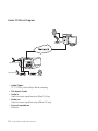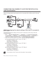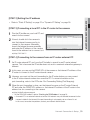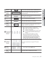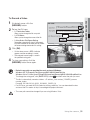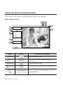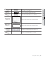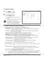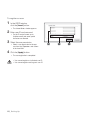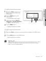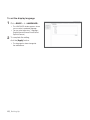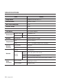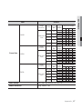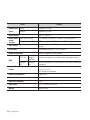
1
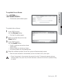
SNC-M300 ENG FRA GER SNC-M300 user manual SPA ITA imagine the possibilities Thank you for purchasing this Samsung product. To receive more complete service, please register your product at www.samsung.com/global/register safety precautions CAUTION RISK OF ELECTRIC SHOCK. DO NOT OPEN CAUTION: TO REDUCE THE RISK OF ELECTRIC SHOCK, DO NOT REMOVE COVER (OR BACK)NO USER-SERVICEABLE PARTS INSIDEREFER SERVICING TO QUALIFIED SERVICE PERSONNEL This symbol indicates that dangerous voltage consisting a risk of electric shock is present within this unit. This symbol indicates that there are important operating and maintenance instructions in the literature accompanying this unit. WARNING • To reduce the risk of fire or electric shock, do not expose this appliance to rain or moisture. • The camera is to be only connected to PoE networks without routing to the outside plant. WARNING 1. Be sure to use only the standard adapter that is specified in the specification sheet. Using any other adapter could cause fire, electrical shock, or damage to the product. 2. Incorrectly connecting the power supply or replacing battery may cause explosion, fire, electric shock, or damage to the product. 3. Do not connect multiple cameras to a single adapter. Exceeding the capacity may cause abnormal heat generation or fire. 4. Securely plug the power cord into the power receptacle. Insecure connection may cause fire. 5. When installing the camera, fasten it securely and firmly. A falling camera may cause personal injury. 6. Do not place conductive objects (e.g. screwdrivers, coins, metal things, etc.) or containers filled with water on top of the camera. Doing so may cause personal injury due to fire, electric shock, or falling objects. 7. Do not install the unit in humid, dusty, or sooty locations. Doing so may cause fire or electric shock. 8. If any unusual smells or smoke come from the unit, stop using the product. In such case, immediately disconnect the power source and contact the service center. Continued use in such a condition may cause fire or electric shock. 9. If this product fails to operate normally, contact the nearest service center. Never disassemble or modify this product in any way. (SAMSUNG is not liable for problems caused by unauthorized modifications or attempted repair.) 10. When cleaning, do not spray water directly onto parts of the product. Doing so may cause fire or electric shock. CAUTION 1. Do not drop objects on the product or apply strong shock to it. Keep away from a location subject to excessive vibration or magnetic interference. 2. Do not install in a location subject to high temperature (over 122°F), low temperature (below 14°F), or high humidity. Doing so may cause fire or electric shock. 3. If you want to relocate the already installed product, be sure to turn off the power and then move or reinstall it. 4. Remove the power plug from the outlet when then there is a lightning. Neglecting to do so may cause fire or damage to the product. 5. Keep out of direct sunlight and heat radiation sources. It may cause fire. 6. Install it in a place with good ventilation. 7. Avoid aiming the camera directly towards extremely bright objects such as sun, as this may damage the CCD image sensor. 8. Apparatus shall not be exposed to dripping or splashing and no objects filled with liquids, such as vases, shall be placed on the apparatus. 9. The Mains plug is used as a disconnect device and shall stay readily operable at any time. important safety instructions 1. 2. 3. 4. 5. 6. 7. Read these instructions. Keep these instructions. Heed all warnings. Follow all instructions. Do not use this apparatus near water. Clean only with dry cloth. Do not block any ventilation openings. Install in accordance with the manufacturer’s instructions. 8. Do not install near any heat sources such as radiators, heat registers, or other apparatus (including amplifiers) that produce heat. 9. Do not defeat the safety purpose of the polarized or grounding-type plug. A polarized plug has two blades with one wider than the other. A grounding type plug has two blades and a third grounding prong. The wide blade or the third prong is provided for your safety. If the provided plug does not fit into your outlet, consult an electrician for replacement of the obsolete outlet. 10. Protect the power cord from being walked on or pinched particularly at plugs, convenience receptacles, and the point where they exit from the apparatus. 11. Only use attachments/accessories specified by the manufacturer. 12. Use only with cart, stand, tripod, bracket, or table specified by the manufacturer, or sold with the apparatus. 13. Unplug this apparatus. When a cart is used, use caution when moving the cart/apparatus combination to avoid injury from tip-over. 14. Refer all servicing to qualified service personnel. Servicing is required when the apparatus has been damaged in any way, such as powersupply cord or plug is damaged, liquid has been spilled or objects have fallen into the apparatus, the apparatus has been exposed to rain or moisture, does not operate normally, or been dropped. contents Preparation 03 Installation and Connection 08 Network Connection & Setup 17 Setting Static IP 03 03 04 04 04 04 05 Features Precautions – Installation and Use Recommended PC Specifications Compatible IP Routers Compatible PoE Switches Checking the components in the package Names of each part 08 12 Installing the Camera Connecting 18 21 Connecting the camera to an IP router with local area networking Connecting the camera directly to local area networking Searching for the camera 22 25 Manual Network Setting Automatic Network Setting 26 27 Dynamic IP Setting Port Forwarding (Port Mapping) Setting 20 22 Setting Dynamic IP 26 Contents _01 Using the Camera 28 Setting Up 41 Appendix 64 02_ Contents 28 30 32 36 Connecting to the camera Installing ActiveX Using the Viewer Screen Using the Search Viewer Screen 41 43 49 54 55 62 Setting the camera Basic Configuration System configuration Layout Configuration Event Configuration Network Configuration 64 66 Troubleshooting Specifications preparation FEATURES Monitoring Through Web Browser Monitoring Through Web Browser This product enables watching a video through an Internet web browser so that you can watch a video through the Internet as you can within the local network. Automatic Local IP Setting Function This function offers an easy way of configuring the network settings with a minimal key input for those who are not familiar with it. Alarm Function If this product is connected with a motion sensor and the sensor detects a motion, a recorded video clip is sent through the FTP/Email(SMTP) registered by the user or saved on the SDHC memory card and a signal is sent to an alarm output port. Motion Detection Function If the user specifies a target area to monitor and the motion sensor detects a motion within that area, a still image is sent to the FTP/Email(SMTP) server designated by the user or saved on the SDHC memory card, and signals are sent to the alarm output terminal. PRECAUTIONS – INSTALLATION AND USE 䭓 Do not disassemble your camera. 䭓 Always be cautious when handling your camera. 䭓 Do not subject the camera to impact or vibration and always be cautious of damaging the camera 䭓 䭓 䭓 䭓 䭓 䭓 䭓 䭓 䭓 due to neglectful storage and/or operation. Do not install the camera at a location where it would become exposed to rain or humidity and do not operate the camera in a wet environment. Do not clean the camera’s main body using harsh abrasives or similar substances. If dirty, use a dry piece of cloth to clean instead. Install the camera in a shaded area or environment, protected from direct sunlight. Direct sunlight exposure has a negative effect on the camera. Do not bend or throw the SDHC memory card. Do not store or use the SDHC memory card in a hot, humid, or dusty environment. Protect the contacts of the SDHC memory card from foreign substance buildup. If foreign substances have been built up on the contacts, remove using a soft piece of cloth. When removing the SDHC memory card, disable SD Card Recording to protect against data loss (refer to page 57 for instruction on disabling SD Card Recording). Data cannot be stored on SDHC memory cards whose service life has expired. Please purchase a new SDHC memory card if you experience this. The manufacturer will not be held responsible for data loss incurred by the customer due to improper use. Using non-recommended PoE device may cause malfunction of either the camera or PoE device itself. (Refer to page 4 for the compatible PoE Switch) Preparation _03 01 PREPARATION Various Communication Protocol Support This product supports various communication protocols such as ARP, HTTP and DHCP as well as TCP/IP, UDP, SMTP for Email transmission and FTP protocol. RECOMMENDED PC SPECIFICATIONS 䭓 CPU: Pentium4/2.4GHz or higher 䭓 Operating System: Windows XP(Service Pack2) / Windows Vista 䭓 Resolution: 1024X768 pixels or higher 䭓 RAM: 512MB or higher 䭓 Web Browser: Internet Explorer 6.0 or higher 䭓 Video Card: Radeon, Nvidia 䭓 Video Memory: 128MB 䭓 DirectX 8.1 or higher COMPATIBLE IP ROUTERS 䭓 Linksys 䭓 D-Link 䭓 Netgear COMPATIBLE POE SWITCHES 䭓 Linksys SRW224G4P 䭓 D-Link DES-1316 䭓 SMC SMCPWR-INJ3 CHECKING THE COMPONENTS IN THE PACKAGE Make sure that the following items are included in the package. Camera User's Manual C Mount Adapter Auto Iris Lens Connector Options Software CD 04_ Preparation CS Lens C Lens NAMES OF EACH PART 01 PREPARATION Front 1 1 Back Focus Adjustment Bar Adjust Back Focus by moving this bar up or down. 䭓When the camera lens becomes dirty, softly clean it with a lens tissue or a cloth soaked in pure ethanol. Preparation _05 Rear 1 3 2 4 6 7 8 5 1 Audio Out For outgoing audio signals. 2 Audio In For incoming audio signals. 3 SDHC Memory Card Slot This is where you insert your SDHC memory card. 4 System, SD, and Power Indicators These indicators provide system, SD, and power status information. Used to connect the camera to an external device. 5 6 I/O Port Reset Button 䭓 䭓 䭓 䭓 A_IN 1 and 2: These are alarm in ports. GND: This is the GND port. A_OUT 1 and 2: These are alarm out ports. NOT USED: This port is not used. Reverts all camera settings to their default. When it is pressed for 3 seconds, the system indicator goes out and the system reboots. When the camera is reset, connection is possible only after the basic network settings (IP address, subnet mask, gateway, etc.) have been configured again using the IP installer program. 06_ Preparation 7 Ethernet Port Ethernet cable port. LED Status Turns on SYSTEM Flashes Turns off 8 Power Port Turns on SD Flashes Turns off PWR Turns on Turns off Description When the power is switched on and the network connection is normal. When the DDNS setting fails. When the DDNS is being set. When the network connection is not stable. When the power is switched off. When the camera is rebooting. When the memory card is inserted and the system is in normal operation. When recording fails. When the memory card is short of capacity. When the memory card is not inserted normally. When the power is switched off. When the camera is rebooting. When the memory cared is removed. When the power is switched on. When the power is switched off. Preparation _07 01 PREPARATION Connect the power cable to this port. installation and connection INSTALLING THE CAMERA Disconnect the power cord before installation or relocation. Mounting the lens When using the CS lens CS lens Mount the CS lens by rotating it clockwise as shown in the picture. When using the C lens C lens After mounting the C-mount adapter by rotating it clockwise, turn the C lens clockwise until it is fixed as shown in the picture. 08_ Installation and Connection Adjusting the back focus In case of the lens with no zooming function 1 After exposing the camera to an object with high resolution (like a dart-patterned image) at a distance of more than 10m, set the lens focus ring to infinite (). 2 Adjust the Back Focus Control Bar until the object is of best quality. 3 Fix the screw of the Back Focus Control Bar. In case of the lens with zooming function 1 After exposing the camera to an object with high resolution (like a dart-patterned image) at a distance of 3 to 5m, fully rotate the lens zoom to the TELE direction. Then adjust the lens focus ring until the object is of best quality. 2 Fully rotate the lens zoom to the WIDE direction and adjust the Back Focus Control Bar until the object is of best quality. 3 Repeat step 1 and 2 two or three times until the focuses of Zoom TELE and Zoom WIDE are clear enough. Installation and Connection _09 02 INSTALLATION AND CONNECTION The back focus of the camera is adjusted at the factory before delivery but some lenses can be out of focus depending on the lens type. In this case, you have to adjust the back focus. The following describes how to adjust the back focus of the lenses. Inserting/Removing an SDHC Memory Card Inserting an SDHC Memory Card Push the SDHC memory card in the direction of the arrow shown in the diagram. 䭓Do not force the memory card in. If you can’t insert the memory card into the slot with ease, you might be inserting the card in the wrong direction. Forcibly inserting a memory card could lead to its damage. Removing an SDHC Memory Card Gently press down on the exposed end of the memory card as shown in the diagram to eject the memory card from the slot. 䭓Pressing too hard on the SDHC memory card can cause the card to shoot out uncontrollably from the slot when released. 䭓 When removing the SDHC memory card, disable the SD Card Recording feature (refer to page 57 for instructions on disabling SD Card Recording). Removing the SDHC memory card while recording is in progress can damage the data. 10_ Installation and Connection Memory Card Information (not included) The memory card is an external data storage device that has been developed to offer an entirely new way to record and share video, audio, and text data using digital devices. Selecting a memory card that’s suitable for you Your camera supports SDHC memory cards. You may, however, experience compatibility issues depending on the model and make of the memory card. Your camera supports SD memory cards. However, the maximum supported SD memory card capacity is 2GB and ver 1.1, 4GB or above SD memory cards are incompatible. For your camera, we recommend you use a memory card from the following manufacturers: SDHC/SD Memory Card: Panasonic®, SanDisk®, and Toshiba® Your camera supports 128MB to 16GB of memory card capacity. Playback performance can be affected depending on the read/write speed of the memory card, so use a high-speed memory card. We recommend you use a memory card with a read/write speed of at least 10Mbps and Class 6 specifications. Memory Card Use SD and SDHC memory cards feature a switch that disables writing data on to the media. Having this switch to the Lock position will prevent accidental deletion of data stored in the memory card but at the same time will also prevent you from writing data on to the media. Memory Card Components Contacts Lock Switch SDHC Installation and Connection _11 02 INSTALLATION AND CONNECTION What is a memory card? CONNECTING Connecting Ethernet Cable Connect the Ethernet cable to the network port as shown. 12_ Installation and Connection Connecting Power 02 INSTALLATION AND CONNECTION 1 2 Connect the power adapter to the camera’s power port. 3 4 Connect the power cord to the power adapter unit. Using a flathead screwdriver, connect the two lines leading from the power adapter to the camera’s power port. Connect the power plug to a power outlet. 䭓Beware of DC 12V’s polarity charges when making the connection. 䭓If you are using a PoE (Power over Ethernet) supporting router, you do not need a separate power source. Installation and Connection _13 To connect input and output ports: Connect alarm lines to the input and output ports on the rear. A_IN 1, A_IN 2 : These are alarm in ports. GND : This is the GND port. A_OUT 1, A_OUT 2 : These are alarm out ports. Alarm In/Out Connection Diagram A_IN1 1 A_IN2 2 GND 3 External Relay A_OUT1 4 External Relay A_OUT2 5 Not Used 14_ Installation and Connection 6 Connecting to Audio Input/Output 02 INSTALLATION AND CONNECTION Microphone LINE-IN LINE-OUT Speaker Microphone 1 Pre-Amp Pre-Amp Connect the AUDIO IN port of the camera with the microphone directly or LINE OUT port of the amplifier that the microphone is connected to. Direct Mic Connection: Set Audio Input Gain high (10). (Refer to page 43) Line Out Connection: Set Audio Input Gain low (1). (Refer to page 43) 2 Connect the AUDIO OUT port of the camera with the LINE IN port of the speaker. Installation and Connection _15 Audio I/O Block Diagram PC Microphone Microphone Pre-Amp Pre-Amp Speaker 䭓 Audio Codec G.711 PCM, μ-law 64kbps 8kHz sampling 䭓 Full duplex Audio 䭓 Audio in Used for mono signal line input (Max.2.4 Vpp) 䭓 Audio out Used for mono signal line output (Max.2.4 Vpp) 䭓 Line out impedance 600ohm 16_ Installation and Connection network connection & setup You can set up the network settings according to your network configurations. 䭓 Connect the camera to an IP router with local area networking Page 18~19 䭓 Connect the camera directly to local area networking Page 20 䭓Compliant IP routers are as listed below. - Linksys - D-Link - Netgear 䭓Compliant PoE Switches are as listed below. - Linksys SRW224G4P - D-Link DES-1316 - SMC SMCPWR-INJ3 䭓Using non-recommended IP router may cause the network connection error. 䭓Depending on the performance of the PC (Viewer installed) or the network, the video transmission can be delayed or even disconnected. For soft video transmission, you can set the bandwidth in <NETWORK> ´ <STREAMING SETUP> in the setup menu. 䭓The IP and MAC addresses used in this manual are for illustrative purposes only. Therefore, you must refer to Notice the network settings of your PC and do not enter the addresses presented in this manual. Network Connection & Setup _17 03 NETWORK CONNECTION & SETUP Network connection and setup processes are given as follows. CONNECTING THE CAMERA TO AN IP ROUTER WITH LOCAL AREA NETWORKING This is for a large network environment such as corporate office, building, public office and factory. SNC-M300 SNC-M300 IP Router External Remote PC Firewall Local PC Local PC DDNS Server (Data Center, KOREA) [STEP 1] Configuring the network settings of the local PC connected to an IP router Configuring the network settings of the local PC connected to an IP router, follow the instructions below. 䭓 Select : <Network Neighborhood> ´ <Properties> ´ <Local Area Connection> ´ <Properties> ´ <General> ´ <Internet Protocol (TCP/IP)> ´ <Properties> ´ <Obtain an IP address automatically> or <Use the following IP address> 䭓 Follow the instructions below if you select <Use the following IP address>: ex1) If the address (LAN IP) of the IP router is 192.168.1.1 IP address: 192.168.1.100 Subnet Mask: 255.255.255.0 Default Gateway: 192.168.1.1 ex2) If the address (LAN IP) of the IP router is 192.168.0.1 IP address: 192.168.0.100 Subnet Mask: 255.255.255.0 Default Gateway: 192.168.0.1 ex3) If the address (LAN IP) of the IP router is 192.168.xxx.1 IP address: 192.168.xxx.100 Subnet Mask: 255.255.255.0 Default Gateway: 192.168.xxx.1 䭓For the address of the IP router, refer to the product’s documentation. 18_ Network Connection & Setup [STEP 2] Setting the IP address [STEP 3] Connecting a local PC in the IP router to the camera 1 Run the IP Installer on your local PC and search for the camera. 2 If found, double-click the camera to start the Internet browser and try to connect to the camera. Alternately, launch the Internet browser manually and enter the IP address of the camera found in the address bar to connect to it. ex) http://192.168.1.2 [STEP 4] Connecting to the camera from an IP router external PC 1 An IP router external PC can’t use the IP Installer to search for an IP router internal camera. This is because the IP Installer does not work in a network where the gateway is different. 2 In this case, you can use the DDNS URL of the camera or the Internet IP address of the IP router to connect to the IP router internal camera. 3 However, you must set the port-forwarding for the IP router before you can connect to the IP router internal camera from a remote PC. For more information on the port-forwarding, refer to Use IP Router: Port Forwarding Setting (Port Mapping). 4 When the port forwarding is done, run the Internet browser on the IP router External PC and enter the DDNS URL address or, the Internet IP address of the IP router in the address bar for connecting to the camera. ex) http://mfffe42.websamsung.net 䭓 For the DDNS URL address, refer to “Checking the DDNS address” on page 29. 䭓A remote PC in an external Internet out of the LAN network may not be able to connect to the camera installed in the intranet if the port-forwarding is not properly set or a firewall is set. In this case, to resolve the problem, contact your network administrator. Network Connection & Setup _19 03 NETWORK CONNECTION & SETUP 䭓 Refer to "Static IP Setting" on page 22 or "Dynamic IP Setting" on page 26. CONNECTING THE CAMERA DIRECTLY TO LOCAL AREA NETWORKING SNC-M300 External Remote PC SNC-M300 Firewall Local PC DDNS Server (Data Center, KOREA) Connecting to the camera from a local PC in the LAN 1 Launch an Internet browser on the local PC. 2 Enter the IP address of the camera in the address bar of the browser. 䭓A remote PC in an external Internet out of the LAN network may not be able to connect to the camera installed in the intranet if the port-forwarding is not properly set or a firewall is set. In this case, to resolve the problem, contact your network administrator. 20_ Network Connection & Setup SEARCHING FOR THE CAMERA 03 NETWORK CONNECTION & SETUP IP Installer screen layout 1 2 3 4 7 5 8 6 9 10 1 Device Name : Model name of the connected device. 2 Mode : Shows the current selection between <Static>and <Dynamic>. 3 Mac Address : The Mac address of the network interface of the camera that is printed on the rear panel. 4 IP Address : The IP address of the camera. (Default setting is '192.168.1.200'.) 5 UPnP Status : This is unavailable for this camera. 6 URL : This is DDNS address that can be used to connect from an external Internet. However, if the DDNS update fails, it will be displayed as an IP address of the camera. 7 Search Button : Searches for the camera connected to the current network. 8 Auto Set Button : Sets up the camera network settings automatically using the <IP Installer>. 9 Manual Set Button : Allows the user to set up the camera network settings manually. 10 Exit Button : Exits the IP Installer program. 䭓On Windows Vista, the settings should be configured by the Administrator to use the IP installer normally. Network Connection & Setup _21 setting static ip MANUAL NETWORK SETTING Run the <IP Installer.exe> program and display the camera list found on the screen. For the initial run, the [Auto Set] and [Manual Set] button are all disabled. 1 Select a camera you want from the camera list. 1 䭓 Confirm the MAC Address of the camera on its rear panel. 䭓 The [Auto Set] and [Manual Set] button are activated. 2 Click the [Manual Set] button. 2 䭓 The Manual Set window appears. 䭓 The <IP Address>, <Subnet Mask>, <Gateway> and <HTTP Port> values of the camera are displayed in their default values. 䭓 The password is set to “4321” by factory default. 3 Set up the IP related settings in the <ADDRESS>field. 䭓 <MAC Address>: The MAC Address printed on the camera rear penal is automatically displayed. No additional setting is required. 3 <If using an IP router> 䭓 <IP Address>: Set it according to the private IP address range provided by the IP Router. ex) 192.168.1.2~254, 192.168.0.2~254, or 192.168.XXX.2~254 䭓 <Subnet Mask>: The IP Router’s <Subnet Mask> becomes camera’s <Subnet Mask>value. 䭓 <Gateway>: The IP Router’s <LAN IP Address> becomes camera’s <Gateway>value. <If not using an IP router> 䭓 For the <IP Address>, <Gateway> and <Subnet Mask> settings, contact your network administrator. 3 22_ Setting Static IP 4 4 In the <PORT>fields, set up port numbers. 䭓 <HTTP Port>: A HTTP port used to connect to a camera using the Internet browser. The default value is 80. The HPPT port value can be changed by using the up/down button to the right. The HTTP port number starts 5 6 with 80 and increases/decreases to 10000, 10006, 10012… 䭓 <Device Port>: A port used to control video transmission. The default value is 60001(TCP). 䭓 <TCP Port>: A port used to transfer video using TCP protocol. The default value is 60002(TCP). 䭓 <UDP Port>: A port used to transfer video using UDP protocol. The default value is 60003(UDP). 䭓 <Upload Port>: A port used to upgrade software. The default value is 60004(TCP). 䭓 <Multicast Port>: Shows UDP port set for video transmission using UDP Multicast. The default value is 60005(UDP). 5 Enter your password. 6 Click the [OK] button. 䭓 The default password is “4321”. 䭓 The password is the camera login password of the root user. 䭓 The manual network setting is finished. 7 The camera is set to the manually entered IP and is restarted. Setting Static IP _23 04 SETTING STATIC IP 䭓You can’t change the port numbers of Device, TCP, UDP, Upload and Multicast, which are automatically changed according to the increase/decrease of the port number of HTTP. If more than one camera are connected to an IP Router Set the IP and port settings for camera differently. Items 1st Camera 2nd Camera IP Related Items IP Address Subnet Mask Gateway 192.168.1.200 255.255.255.0 192.168.1.1 192.168.1.201 255.255.255.0 192.168.1.1 Port Related Items HTTP Port Device Port TCP Port UDP Port Upload Port Multicast Port 80 60001 60002 60003 60004 60005 10000 10001 10002 10003 10004 10005 䭓If <HTTP Port>is not set to 80,the user must specify the port number as well as the IP address in the Address input box of an Internet browser to connect to the camera. Example) http://IP Address: HTTP Port e.g.) http://192.168.1.201: 10000 24_ Setting Static IP AUTOMATIC NETWORK SETTING 04 SETTING STATIC IP Run the <IP Installer.exe> program and display the camera list found on the screen. For the initial run, the [Auto Set] and [Manual Set] button are all disabled. 1 Select a camera you want from the camera list. 1 䭓 Confirm the MAC Address of the camera on its rear panel. 䭓 The [Auto Set] and [Manual Set] button are activated. 2 Click the [Auto Set] button. 2 䭓 The Auto Set window appears. 䭓 The automatically found <IP Address>, <Subnet Mask>and <Gate Way> are displayed. 3 Enter your password. 䭓 The password is the camera login password of the root user. 䭓 The default password is “4321”. 4 Click the [OK] button. 䭓 The automatic network setting is finished. 5 The camera automatically restarts when the network setting is complete. 4 3 Setting Static IP _25 setting dynamic ip DYNAMIC IP SETTING Examples of using Dynamic IP 䭓 If the camera is installed on an IP router and obtains an IP using DHCP 䭓 If the camera is connected directly to a xDSL/Cable modem using DHCP 䭓 If an IP is allocated by the internal DHCP server in local area networking Dynamic IP Check 1 2 1 When you run the IP Installer on your local PC, the camera with a dynamic IP allocated is listed. 2 Select the camera in the list and click the [Manual Set] button to check the camera for the current dynamic IP. 䭓 In this case, the ADDRESS field is automatically filled and you can’t change it. However, you can still change the port settings. 26_ Setting Dynamic IP PORT FORWARDING (PORT MAPPING) SETTING Manual Port Forwarding 1 1 Click <Applications &Gaming> ´ <Port Range Forward> from the Settings menu of the IP Router. 䭓 For the menu location and the setting of Port Forwarding, refer to the IP router’s documentation. 2 Select the <TCP> and <UDP Port> for each camera connected to the IP Router. 䭓 Each of the port numbers for the IP Router must be according to those presented in <BASIC> ´ <IP> of the SETUP screen of the camera. 3 If the setting is complete, click the [Save Settings] button. 2 3 䭓 The changes are saved. Setting Dynamic IP _27 05 SETTING DYNAMIC IP With the camera installed on an IP router, you must set the port forwarding for the IP router before an IP router external remote PC can connect to the IP router internal camera. _]SXQ ^RO MKWO\K CONNECTING TO THE CAMERA Connecting to the camera General 䭓 Run an Internet browser. 䭓 Enter the IP address for the camera in the Address input box. Example) IP Address: 192.168.1.200 ´ http://192.168.1.200 - The Login screen appears. If the HTTP port number is not 80 䭓 Run an Internet browser. 䭓 Enter the IP address and the HTTP port number for the camera in the Address input box. Example) IP Address: 192.168.1.200:Port Number(10000) ´ http://192.168.1.200:10000 - The Login screen appears. Connection using URL 䭓 Run an Internet browser. 䭓 Enter the DDNS URL for the camera in the Address input box. Example) URL Address: http://mfffe42.websamsung.net - The Login screen appears. Connection using URL (If the HTTP port number is not 80) 䭓 Run an Internet browser. 䭓 Enter the DDNS URL and the HTTP port number for the camera in the Address input box. Example) URL Address: http://mfffe42.websamsung.net:Port Number(10000) ´ http://mfffe42.websamsung.net:10000 - The Login screen appears. 28_ Using the camera Checking the DDNS address Example) - If the MAC address of the camera is 00 : 00 : f0 : ff : fe : 42 : c + fffe42 + websamsung.net = cfffe42.websamsung.net - If the MAC address of a camera is 00 : 16 : 6c : ff : fe : 42 : m + fffe42 + websamsung.net = mfffe42.websamsung.net - If the MAC address of a camera is 00 : 68 : 36 : ff : fe : 42 : p + fffe42 + websamsung.net = pfffe42.websamsung.net 䭓The IP and MAC addresses are used in this manual for illustrative purposes only. Therefore, you must not enter Notice the addresses presented in this manual when you setting your equipment. Connecting to the camera using the IP Installer program Double-click a camera you want from the search result screen. 䭓 The Login screen appears. 䭓 If the ActiveX window appears, install it referring to the next page. Using the camera _29 06 USING THE CAMERA 䭓 A DDNS address consists of <One among from lower-case alphabet characters of c, m and p> + <Last 6 digits of the MAC address> + <websamsung.net>. 䭓 The lower-case alphabet letter is represented as <c>if the first 6 digits of the MAC address is <00:00:f0>, <m> if <00:16:6c>, and <p> if <00:68:36>. INSTALLING ACTIVEX If you connect the camera to the Internet and configure the network settings, you can monitor the picture of the connected camera in real-time. For Windows XP Service Pack 2 1 If the following screen appears, click the Install button. 2 Click the <Install ActiveX Control>. 3 If the Security Warning window appears, click the [Install] button. 1 3 䭓For successful installation, disable the pop-up blocker by going to the option below. Internet Explorer p Tools p Pop-up blocker p Always Allow Pop-ups from This Site 30_ Using the camera Logging to the camera 06 USING THE CAMERA For the first login, the user ID is “root” and password is “4321”. 1 Type root in the <User ID>input box. 2 Type 4321 in the <Password> input box. 䭓 If you have changed the old password, type the new password here. 3 Click the [Log In] button. 1 2 3 䭓 When the login is complete, the camera Viewer screen appears. 䭓For the security purposes, make sure to change the password by clicking <BASIC> ´ <USER> in the SETUP screen. The administrator ID, root is fixed and cannot be changed. 䭓If you select the <Save ID> check box, the user ID is saved and will be entered automatically in the following logins. 䭓You are required to install DirectX 8.1 or later on your Windows-based PC. 䭓You can download DirectX for free at http://www.microsoft.com/download Using the camera _31 USING THE VIEWER SCREEN If you connect to the camera, the following Viewer screen appears. Main Screen Layout 1 2 3 4 5 6 13 8 7 9 10 11 12 Name 1 LIVE Button Function and Description Moves to the main screen. You can search stored video data using date parameters. 䭓 The date can be adjusted from the calendar 2 SEARCH window. 䭓 Recording image can be searched using the timeline. 䭓 Available commands include Play, Pause, Fast Forward, and Rewind. 3 SETUP 32_ Using the camera Moves to the setup screen. 4 ABOUT Status window 6 Capture button Displays the model name and the address of the connected device. Captures the current picture on the screen and saves it as a .jpeg or .bmp image file. 7 Print button Prints the current picture on the screen. 8 Record Saves the current video as a .avi video file. button 9 Video Channel Selection 10 Screen Size & Partition Buttons 11 Camera function buttons 12 Audio buttons 13 View Screen Displays the information of the current video channel between <MJPEG> and <MPEG4>. 䭓 You can select a screen size as shown below. 䭓 : Displays the video in its original size. 䭓 : Zooms-out the video size to its 1/4 and displays it in the center. 䭓 : Displays the video fitting to the viewer screen size. The aspect ratio of the video may be different. 䭓 : You can see the image in full screen. 䭓 Pressing the ESC key from full screen mode restores the display back to split screen mode. If the display does not switch over to normal split screen, alt+tab and then select Active Movie. From here, press the ESC key to make the switch. This camera model does not support PTZ control functions. 䭓 Listen, Speak, Volume ST button The current video is displayed on live screen. Using the camera _33 06 USING THE CAMERA 5 Connection You can view information, version, manufacturer, etc. To Capture a Video 1 At a desired scene, click the [CAPTURE] button. 䭓 The capture confirmation window appears. 2 Click [OK]. 䭓 The captured screen image is saved in the specified folder path. 䭓Default save paths are provided for each version of Windows. Windows XP: C:\Program Files\Samsung\SNC-M300\SnapShot\Live Windows Vista: C:\users\[user ID]\AppData\LocalLow\Samsung\SNC-M300\SnapShot\Live To change the saving path, click [SAVE PATH] button( ) and then select the path you want. 䭓The file is automatically named as follows: <IP address_Port number_YYMMDD_camera number_index> Example) 192.168.130.40_60001_20080601_203523_00 䭓The save path cannot be changed if you are using Windows Vista. To Print a Video 1 At a desired scene, click the [PRINT] button. 䭓 The print setup window appears. 2 Click [OK]. The captured screen image is printed. 34_ Using the camera To Record a Video At desired scene, click the [RECORD] button. 2-1 2 3 4 Set up the AVI save. 2-2 䭓 2-1 Destination Folder: Allows you to change the file save path. 䭓 2-2 File Name: Allows you to change the name of the file. 䭓 2-3 Insufficient Disk Space Setting: Recording automatically stops if the amount of space available on the hard disk falls below the amount designated under this setting. 2-3 3 REC Click [OK]. 䭓 On the viewer screen, <REC> indicator appears and the recording is started. 䭓 The captured screen image is saved in the specified saving path. To stop a recording, click the [RECORD] button once again. 䭓Default save paths are provided for each version of Windows. Windows XP: C:\Program Files\Samsung\SNC-M300\VidedClip\Live Windows Vista: C:\users\[user ID]\AppData\LocalLow\Samsung\SNC-M300\SnapShot\Live To change the saving path, click [SAVE PATH] button( ) and then select the path you want. 䭓The file is automatically named as follows: <IP address_Port number_YYMMDD_camera number_index> Example) 192.168.130.40_60001_20080601_203523_00 䭓For AVI Save, you need the DivX codec for playing saved files. You can download the free version of the Divx codec at http://sourceforge.net/projects/ffdshow/. 䭓The save path cannot be changed if you are using Windows Vista. Using the camera _35 06 USING THE CAMERA 1 USING THE SEARCH VIEWER SCREEN If you connect to the camera, the following Search Viewer screen appears. Main Screen Layout 1 2 3 4 5 6 12 8 7 9 10 11 Name Button Function and Description 1 Live tab Moves to the main screen. 2 Search You can search stored video data using date parameters. tab 3 Setup tab Moves to the setup screen. 4 About tab You can view information, version, manufacturer, etc. 5 Connection Status window 36_ Using the camera Displays the model name and the address of the connected device. 6 Capture 9 Calendar Selection 10 Timeline Display Prints the recorded image on the screen. Saves the recorded video as a .avi video file. Searches the recorded video using the calendar. Searches the recorded video using the timeline. 11 Playback function buttons 12 View Screen Playbacks the recorded video with various way. Displays the recorded video on live screen. Using the camera _37 06 USING THE CAMERA button 7 Print button 8 Record button Captures the recorded image on the screen and saves it as a .jpeg or .bmp image file. To Capture a Video 1 At a desired scene, click the [CAPTURE] button. 䭓 The capture confirmation window appears. 2 Click [OK]. 䭓 The captured screen image is saved in the specified folder path. 䭓Default save paths are provided for each version of Windows. Windows XP: C:\Program Files\Samsung\SNC-M300\SnapShot\Search Windows Vista: C:\users\[user ID]\AppData\LocalLow\Samsung\SNC-M300\SnapShot\Search To change the saving path, click [SAVE PATH] button( ) and then select the path you want. 䭓The file is automatically named as follows: <IP address_Port number_YYMMDD_camera number_index> Example) 192.168.130.40_60001_20080601_203523_00 䭓The save path cannot be changed if you are using Windows Vista. To Print a Video 1 At a desired scene, click the [PRINT] button. 䭓 The print setup window appears. 2 Click [OK]. The captured screen image is printed. 38_ Using the camera To Record a Video At desired scene, click the [RECORD] button. 2 Click [OK]. 3 06 USING THE CAMERA 1 䭓 On the viewer screen, <REC> indicator appears and the recording is started. 䭓 The captured screen image is saved in the specified saving path. To stop a recording, click the [RECORD] button once again. REC 䭓Default save paths are provided for each version of Windows. Windows XP: C:\Program Files\Samsung\SNC-M300\SnapShot\Search Windows Vista: C:\users\[user ID]\AppData\LocalLow\Samsung\SNC-M300\SnapShot\Search To change the saving path, click [SAVE PATH] button( ) and then select the path you want. 䭓The file is automatically named as follows: <IP address_Port number_YYMMDD_camera number_index> Example) 192.168.130.40_60001_20080601_203523_00 䭓For AVI Save, you need the DivX codec for playing saved files. You can download the free version of the Divx codec at http://sourceforge.net/projects/ffdshow/. 䭓The save path cannot be changed if you are using Windows Vista. Using the camera _39 To Search the Video Data 1 From the calendar, select the date you wish to search. 䭓 Video data associated with that date will than appear. 2 Select the timeframe you wish to search, using the timeline. 䭓Clicking on the [Today] button applies today’s date. 䭓 䭓 : Displays a two-hour zone and enables search in five-minute intervals. : Displays a 24-hour zone and enables search in one-hour intervals. To Control Playback Button Function Description Reverse-plays faster (2x, 4x, 8x). Performs Reverse Play. Performs playback. Plays faster (2x, 4x, 8x). Moves the beginning time of recorded video in the time line. Performs one step reverse play by one frame. Pauses playback. Performs one step forward by one frame. Moves the last time of recorded video in the time line. 40_ Using the camera setting up SETTING THE CAMERA 07 SETTING UP You can set various functions such as Basic Setting, System, Layout, etc. In the viewer screen, click the [SETUP] tab. The SETUP screen appears. Setting Up _41 SETUP Screen Layout SETUP BASIC VIDEO & AUDIO IP USER LANGUAGE SYSTEM DATE/TIME LOG SOFTWARE UPDATE RESET CAMERA OVERLAY OVERLAY TEXT EVENT TRANSFER SETUP RECORD SETUP ALARM IMAGE ALARM INPUT1 ALARM INPUT2 MOTION SCHEDULE NETWORK STREAMING SETUP DDNS 42_ Setting Up BASIC CONFIGURATION 07 SETTING UP To setup Video/Audio You can set the video resolution, quality, frames per second, and input gain. 1 Click <BASIC> ´ <VIDEO & AUDIO>. 䭓 The VIDEO & AUDIO window appears. 2 To complete the video setting, click the [Apply] button. 䭓 The settings are saved. 䭓You will not be able to hear the audio data if the audio input gain is at zero. 䭓<Resolution>: Select a video size from the options shown below. MJPEG: QXGA(2048x1536), UXGA(1600x1200), SXGA(1280x1024) MPEG: VGA(640x480) 䭓<Quality>: Select a video quality from <Very High>, <High>, <Normal>, <Low> and <Very Low>. 䭓<Frame Rate>: Select a frame rate. MJPEG: QXGA(12ips, 6ips, 3ips, 1ips, Auto), UXGA(19ips, 10ips, 5ips, 1ips, Auto), SXGA(25ips, 13ips, 6ips, 1ips, Auto) MPEG: QXGA(12ips, 6ips, 3ips, 1ips, Auto), UXGA(19ips, 10ips, 3ips, 1ips, Auto), SXGA(25ips, 13ips, 3ips, 1ips, Auto) 䭓<Input Gain>: Select the audio amplification level between 0 and 10 䭓If the frame rate of MJPEG is at its maximum value, the frame rate of MPEG can only be set to 3 ips or 1 ips. Setting Up _43 To Setup IP settings 1 Click <BASIC> ´ <IP>. 2 To complete the setting, click the [Apply] button. 䭓 IP Setting window appears. 䭓 The settings are saved and the system is restarted. 䭓 The currently opened web browser is closed. 䭓When two or more cameras are connected to a single IP sharing device, IP-related settings and port-related settings should be configured differently. 䭓<IP Type>: Shows the current camera IP setting type. - Select the IP setting type from <Static IP> or <Dynamic IP>. 䭓<IP Configuration>: Allows setting the camera and port related settings. - <MAC Address>: Shows the Ethernet MAC address. Since this value is used to create a DDNS address, confirm the value. - <IP Address>: Shows the currently configured IP address. If the <IP Type> is set to <Static IP>, you can change the IP address. - <Subnet Mask>: Shows the <Subnet Mask> for the configured IP address. - <Gateway>: Shows the <Gateway> address for the configured IP address. - <DNS Server>: Shows the IP address of the DNS (Domain Name Service) server. - <HTTP Webserver Port>: Shows the HTTP port used to connect to the camera using the web browser. The default port number is 80(TCP). - <Device Port(TCP)>: A port used to control video transmission. The default value is 60001(TCP). - <TCP Streaming Port>: A port used to transfer video using the TCP protocols. The default value is 60002(TCP). - <UDP Streaming Port>: A port used to transfer video using the UDP multicast protocols. The default value is 60003(UDP). - <Upload Port(TCP)>: A port used to upgrade software. Default value is 60004(TCP). 䭓<Multicast Settings>: To transmit a video using UDP Multicast, you can set the IP address, port and TTL. - <Multicast Address>: Shows IP address set for video transmission using UDP Multicast. The default value is 225.128.1.128. It is recommended to set it to between 224.0.0.0 and 239.255.255.255. - <Multicast Port>: Shows UDP port set for video transmission using UDP Multicast. The default value is 60005(UDP). - <TTL>: TTL stands for “Time To Live” that allows you to set the number of routers so that the packet can pass through. Each router decrease the TTL value one by one when a packet passes it through. If the TTL value reaches 0, the packet cannot pass through a router. The default value is 63. It is recommended to set it to between 0 and 255. 44_ Setting Up To Setup Users Click <BASIC> ´ <USER>. 2 To complete the setting, click the [Apply] button. 07 SETTING UP 1 䭓 The USER window appears. 䭓 The settings are saved and the system is restarted. 䭓 The currently opened web browser is closed. 䭓<Login Authentication>: You can determine whether to require login authentication for users. - If it is set to <Enable>, the users can connect to the system through login authentication, while it is set to <Disable>, the users can connect to the system without login authentication. However, users connected to the system without login have USER permission. - When the setting is complete, click the [Apply] button. 䭓<User Login ID/Password List>: Shows user ID, password and level (permissions) in a list. - You can register up to 10 users. - The default administrator ID is root. - <Administrator> cannot be deleted or added and you can change the password only. Setting Up _45 To register an user 1 In the USER window, click the [Insert] button. 䭓 The <Insert User> window appears. 2 Enter user ID and password. 䭓 For the ID and password, up to 9 alphanumeric and some special characters are allowed. 3 Select the user permission. 䭓 Select a user permission for the new user from the <Operator> and <User> in the Level field. 4 Click the [Apply] button. 䭓 The user registration is completed. 䭓You cannot register a duplicated user ID. 䭓You cannot register root or guest user ID. 46_ Setting Up 2 3 4 To modify a registered user account Select the <Select> check box of a user account to be modified in the USER window. 2 Click the [Modify] button in the USER window. 07 SETTING UP 1 䭓 The <Modify User> window appears. 3 In the window, modify <User ID>, <Password>, <Confirm Password> or <Level> of the user account. 4 Click the [Apply] button. 3 4 䭓 Modifying a registered user is complete. To delete a registered user account 1 Select the <Select> check box of a user account to be deleted in the USER window. 2 Click the [Delete] button in the USER window. 䭓 Deleting a registered user is complete. 䭓About User Level <Administrator>: The Administrator can use all functions and change the setup or search. <Operator>: The Operator can use all functions except setup and playback functions. <User>: The User can monitor video only. Setting Up _47 To set the display language 1 Click <BASIC> ´ <LANGUAGE>. 䭓 The LANGUAGE window appears where you can select a preferred language. 䭓 You can select once from 7 languages (English/Korean/Chinese/French/Italian/ Spanish/German). 2 To complete the setting, click the [Apply] button. 䭓 The language has been changed to the selected one. 48_ Setting Up SYSTEM CONFIGURATION You can get the current system time from a NTP server or a PC and set the system time. 1 Click <SYSTEM> ´ <DATE/TIME>. 䭓 The DATE/TIME window appears. 2 To complete the setting, click the [Apply] button. 䭓 The settings are saved. 䭓The date can be configured between 1 January 2000 and 31 December 2037. 䭓<Current System Time>: Shows the time according to the setting of System Time Setup. 䭓<System Time Setup>: You can set the time synchronized with NTP server (time server) or PC, or manually setup. Setting Up _49 07 SETTING UP To set date/time To setup the system time 1 Select one of the NTP server addresses of the <Address> list, or click <Syncronize with PC Viewer>. 2 Set the date and time directly if you select <Manual>. 3 Click the [Apply] button. 䭓 The setting time is applied. 䭓NTP Server IPs are provided by a public agency and their list is therefore subject to change. 䭓In a local network, a separate NTP server must be manually defined. 䭓The current time can vary depending on the computers regional (GMT and DST) and country (PC time configuration) settings. To view the log information Click <SYSTEM> ´ <LOG>. 䭓 The Log window appears showing log information. 䭓<System Log List>: Shows the log information about the system changes along with time and IP address. - <User Log In>: Shows current camera login user. - <Video Configuration Change>: Shows video setting changes. - <System Time Change>: Shows time changes. - <System Start>: Shows time when the camera is turned on. 䭓The maximum number of logs that can be recorded is 2,000. 䭓If the number goes over 2,000, new logs are added and the bottom-most logs are deleted. 50_ Setting Up To update the software 07 SETTING UP Click <SYSTEM> ´ <SOFTWARE UPDATE>. 䭓 The Software Update window appears. To update the software 1 In the USER window, click the [Browse] button. 䭓 The Open File window appears. 2 Select an update file and click the [Open] button. 3 In the USER window, click the [Install] button. 䭓 The file is uncompressed and the software update begins. 䭓 Software update may take tens of minutes. 䭓 To cancel an update, click the [Cancel] button. 4 When the software update is done, the system will automatically restart. 䭓 Since the current connection is disconnected, you have to connect to the system again. 䭓Since, if the network is disconnected, the power fails or the PC abnormally operates during a software update, the system may not work afterwards, take care not to cause a problem during an update. Setting Up _51 To reset the system If the system abnormally operates or a problem occurs, you can restart or reset the system. Click <SYSTEM> ´ <RESET>. 䭓 The Reset window appears. 䭓<Restart>: The Reset window appears. 䭓<Factory Default>: Initializes the system settings to the factory settings and then restarts the system. - <Except Network Parameter>: Initializes the system settings except network settings. - <All>: Initializes all the system settings. Selecting this option is the same as pressing the [FACTORY RESET] button on the rear panel of the main body. 䭓After reset and restart, you have to connect to the system again. 䭓It takes a few minutes until the system booting is completed. You cannot connect to the system until the system booting is complete. 䭓After running <Factory Default> ´ <All>, you have to run <IP Installer.exe> program and setup network settings such as IP address, Subnet mask, Gateway, etc., to connect to the Internet. 52_ Setting Up To setup the camera 07 SETTING UP 1 Click <SYSTEM> ´ <CAMERA>. 䭓 You can select one from <Image Flip>, <Image>, <White Balance>, <Exposure Mode>, <Adaptive Lighting Mode>, <Power Line>, <Saturation> and <Detail>. 2 To complete the setting, click the [Apply] button. 䭓<Image Flip>: Images can be flipped horizontally or vertically. 䭓<Image>: Images can be set to color or black and-white. 䭓<White Balance>: Color casts can be adjusted so that images in white can normally be seen at any color temperature. <Auto>: The camera can automatically adjust the color temperature in real time according to changes in surroundings. The range of color temperature that can be adjusted is approx. 2000K – 8000K. <Daylight>: A mode set to a color temperature of 6500K. <Tungsten>: A mode set to a color temperature of 2800K. <Office fluorescent>: A mode set to a color temperature of 4000K. <Fluorescent>: A mode set to a color temperature of 4500K. <Horizontal>: A mode set to a color temperature of 2000K. 䭓<Exposure Mode>: The level of exposure can be adjusted by selecting Auto or Manual. (Settings: Auto, Manual (0,1,2,3,4)) <Auto>: Supports the optimum exposure level. <Manual>: A desired exposure level (0 – 4) can be set according to surroundings. 䭓<Adaptive Lighting Mode>: It can improve the lighting effect by increasing the intensity of the light. <Off>: A mode in which the backlight function is turned off. <Normal>: A mode in which both the dark and bright areas are adjusted according to the surroundings. <Backlit>: A mode in which the backlight adjustment function is enhanced. 䭓<Power Line>: The power frequency can be set to 50 Hz or 60 Hz. 䭓<Saturation>: The screen image can be adjusted to desired saturation. (Settings: 0,1,2,3,4,5,6,7,8,9) 䭓<Detail>: Horizontal and vertical sharpness can be adjusted. (Settings: 0,1,2,3,4,5,6,7,8,9) Setting Up _53 LAYOUT CONFIGURATION You can display text on the screen. To Set text 1 Click <OVERLAY> ´ <OVERLAY TEXT>. 䭓 The Overlay Text window appears. 2 To complete the setting, click the [Apply] button. 䭓 The settings are saved. 䭓<Overlay Text Settings>: The <Disable> option hides an overlay text while <Enable> shows it on the screen. 䭓<Show date>: Determines whether to display date on the bottom screen. - <Display format>: Select a date display format. YYYY-MM-DD: Year-Month-Day / MM-DD-YYYY: Month-Day-Year / DD-MM-YYYY: Day-MonthYear 䭓<Show time>: Determines whether to display time on the bottom screen. - <Display format>: Select a date time format. 24hr: Time notation in 24 hours / 12hr: Time notation in 12 hours with AM/PM. 䭓<Text color>: Determines text color. You can select either <White> or <Black>. 䭓<Background color>: Determines text background color. You can select one from <White>, <Black> and <Transparent>. 54_ Setting Up EVENT CONFIGURATION You can set an FTP/Email(SMTP) server to send the prior/posterior alarm image saved in the camera when an alarm is generated. Click <EVENT> ´ <TRANSFER SETUP>. 䭓 The TRNASFER SETUP window appears. 䭓If a commercial SMTP service is used, ask the SMTP service provider for detailed settings. 䭓<FTP Transfer>: You can transfer an alarm image to an FTP server. When the initial FTP server setting and connection are not verified, the <Not verified> message appears. - <Use Passive Mode>: Select this option when the passive mode connection is necessary due to firewall or FTP server setting. - <FTP Server Address>: Enter the IP address of an FTP server to which an alarm image will be sent. - <Upload Path>: You can set the path of the FTP account to transfer an alarm image. You can set a path by just typing </directory name> or <directory name> in this field. If you do not specify a path, alarm files are sent to the root directory of the FTP account. - <Port>: Although FTP server port is 21 as a default, you can change the port number according to the FTP server settings. - <User ID>: Enter a user account ID to connect to login the FTP server. - <Password>: Enter a user account password to login the FTP server. To test FTP transmission Click the [Test] button. 䭓 Connect to the configured FTP server and conduct image transmission test automatically. 䭓 When the FTP server connection and transmission tests are complete, the <Verified> message will be displayed. 䭓 If the test fails, an error message appears. In this case, check the FTP server status and the configured settings once again. Setting Up _55 07 SETTING UP To set the image transmission function 䭓<E-mail(SMTP) Transfer> : You can transfer an alarm image through Email. This function supports SMTP Email server only. When the initial SMTP server setting and connection are not verified, the <Not verified> message appears. - <SMTP Server Address>: Enter the IP address of an SMTP server to be used to send an Email. Example) smtp.hotmail.com - <User ID>: Enter a user account ID to connect to connect the SMTP server. - <Password>: Enter a user account password to the SMTP server. - <E-mail Sender>: Enter the address of the Email sender. If the sender address is incorrect, the Email from the sender may be classified into SPAM mail by the SMTP server and may not be sent. - <E-mail Receiver>: Enter the address of the Email recipient. - <Title>: Enter the title of the Email. - <Message>: Enter the contents of the Email. An alarm image is attached to the Email as an attached file. To test Email transmission Click the [Test] button. 䭓 䭓 䭓 Connect to the configured SMTP server and conduct image transmission test automatically. When the SMTP server connection and transmission tests are complete, the <Verified> message will be displayed. If the test fails, an error message appears. In this case, check the SMTP server status and the configured settings once again. To setup the record 1 Click <EVENT> ´ <RECORD SETUP>. 䭓 The RECORD SETUP window appears. 2 To complete the setting, click the [Apply] button. 䭓 The settings are saved. 䭓 <SD Card>: Enables you to verify data saved on the SDHC memory card and format the memory card itself. It is possible to set to automatically delete movie clips recorded before a certain period of time (e.g. 1 week, 1 month, or 1 year). 䭓 <Options>: Determine whether or not you wish to receive Email notification of insufficient capacity warnings. 56_ Setting Up To set an alarm image 1 Click <EVENT> ´ <ALARM IMAGE>. 䭓 The ALARM IMAGE SETUP window appears. 2 To complete the setting, click the [Apply] button. 1 2 䭓 The settings are saved. 3 1. <Transfer Mode>: You can select a method to send an alarm image from the <FTP>, <E-Mail> and <SD Card Record>. - <FTP Transfer>: The image is sent to the specified FTP address. - <E-Mail Transfer>: The image is sent to the specified Email address. - SD Card Recording X Insert an SDHC memory card. X Configure the SDHC memory card (refer to page 56 for details). X Check the SD Card Recording option and then click on the [Apply] button. The SD indicator will then turn on and recording will commence. X To remove the SDHC memory card, first uncheck the SD Card Recording option and then click on the [Apply] button. Removing the SDHC memory card while recording is in progress can damage the data. 2. <Transferred Image Naming Setup>: You can set the file name of an alarm image to be sent when an alarm is generated or during the scheduled transfer. 3. <Pre/Post Alarm Image>: You can determine which of previous or posterior image is to be sent. - <Number of Image>: Determines number of images to be sent per second. You can select 1 or 2 images per second. - <Pre-Alarm Duration>: Determines time of prior images to be sent. You can select <1 sec> or <3 sec>. You can send a prior image of up to 3 seconds after an alarm is generated. (The maximum time is determined by the number of images to be sent per second.) - <Post-Alarm Duration>: Determines time of posterior images to be sent. You can select <1 sec> or <3 sec>. You can send a posterior image of up to 3 seconds after an alarm is generated. (The maximum time is determined by the number of images to be sent per second.) Setting Up _57 07 SETTING UP You can set an image to be sent through FTP/Email(SMTP) or saved on the SDHC memory card when an alarm is generated or during the scheduled transfer. To set an alarm input 1 Click <EVENT> ´ <ALARM INPUT 1> or <ALARM INPUT 2>. 䭓 The ALARM INPUT window appears. 2 To complete the setting, click the [Apply] button. 䭓 The settings are saved. 䭓<Input Device Setup>: Select an input type from the <OFF>, <NO> and <NC>. - <NO>(Normal Open): It is normally open, but if it is close, an alarm will be generated. - <NC>(Normal Close): It is normally close, but if it is open, an alarm will be generated. 䭓<Activation Time>: You can set time to accept an alarm to take an action. - <Always>: Always conducts the <Action> setting when an alarm is generated. - <Only Scheduled Time>: Conducts the <Action> setting for an alarm only when it occurs during the specified time period on the specified day of the week. The Start Time must prior to and must differ from the End Time. 䭓<Action>: You can set an operation to be conducted when an alarm is generated. - <Alarm Output>: Determines alarm output port to which the alarm signal is to be sent. - <Output Duration>: Determines the period of time to output alarm signal to the specified alarm output port when an alarm is generated. If another alarm event is generated during the alarm output, the delay time is recalculated on the basis of the most recently generated an alarm. - <Alarm Image Transfer>: If <On> is selected, a JPG image is transmitted through FTP or Email (SMTP) or saved on the SDHC memory card according to the <EVENT> ´ <TRANSFER SETUP> settings. 58_ Setting Up To set the motion detection function 07 SETTING UP 1 Click <EVENT> ´ <MOTION>. 䭓 The MOTION window appears. 2 To complete the setting, click the [Apply] button. 䭓 The settings are saved. 䭓<M.D. Function>: <Enable> activates the motion detection function, while <Disable> disables the function. 䭓<M.D. Configuration>: You can set motion detection performance parameters. - <Motion Sensitivity>: Select a motion detection function sensitivity from <High>, <Medium> and <Low>. The <High> option provides high sensitivity of motion detection and generates motion detection event if a small motion is detected. - <Motion Area>: You can set an area to detect motion. 䭓<Activation Time>: You can set time to accept a motion detection to take an action. - <Always>: Always conducts the <Action> setting when a motion is detected. - <Only Scheduled Time>: Conducts the <Action> setting for a motion detection only when it occurs during the specified time period on the specified day of the week. The Start Time must prior to and must differ from the End Time. 䭓<Action>: You can set an operation to be conducted when a motion is detected. - <Alarm Output>: Determines a motion detection output port to which the alarm signal is to be sent. - <Output Duration>: Determines the period of time to output the alarm signal to the specified alarm output port when a motion is detected. If another detection event is generated during the alarm output, the delay time is recalculated on the basis of the most recently generated motion detection. - <Alarm Image Transfer>: If <On> is selected, a JPG image is transmitted through FTP or Email (SMTP) or saved on the SDHC memory card according to the <EVENT> ´ <TRANSFER SETUP> settings. Setting Up _59 To set a motion detection target area You can set a specific area to detect a motion in. 1 In the MOTION window, click the [Motion Area] button. 䭓 The Motion Area window appears. 䭓 You can set a specific area to detect a motion in. 2 Click over square boxes corresponding to your desired motion detection target area. 䭓 The selected area is colored in yellow. 3 To cancel a selection, click over the square box once again. 䭓 The square box returns to its original color. 4 To complete the setting, click the [Apply] button. 䭓 The settings are saved. 䭓 The motions in the selected area will be detected. 60_ Setting Up To set scheduled transmission 1 Click <EVENT> ´ <SCHEDULE>. 䭓 The SCHEDULE window appears. 2 To complete the setting, click the [Apply] button. 䭓 The settings are saved. 䭓<Schedule Transfer Function>: <Enable> activates the scheduled transmission function, while <Disable> disables the function. 䭓<Transfer Interval>: You can set the time interval to transmit images. You can select a unit of time from <SECONDS> or <MINUTES>. You can set the time interval so that an image is transmitted every 5/15/30/45/60 seconds or minutes. 䭓<Activation Time>: You can set the time to execute the scheduled transmission function. - <Always>: Always transmits images according to the specified interval. - <Only Scheduled Time>: Transmits images according to the specified interval during the specified time period on the specified day of the week. 䭓The Start Time must be prior to and must differ from the End Time. Setting Up _61 07 SETTING UP You can have a JPEG image sent through FTP and Email or recorded on the SDHC card periodically. NETWORK CONFIGURATION To set video streaming You can control the data transfer rate according to the camera video streaming type and network bandwidth. 1 Click <NETWORK> ´ <STREAMING SETUP>. 䭓 The STREAMING SETUP window appears. 2 To complete the setting, click the [Apply] button. 䭓 The settings are saved. 䭓<Streaming Type>: You can select a protocol for video transmission from the <TCP>, <UDP(Unicast)> and <UDP(Multicast)>. - <TCP>: It is a general purpose protocol used for a transmission that requires reliability. Since it provides a connection based communication between the sender and recipient, it provides high reliability against transmission data loss. However, it is inappropriate to transmit a large amount of data in real-time because of its transmission overhead. It enables reliable data transmission over xDSL and cable network at a relatively slow speed. - <UDP(Unicast)>: It refers to transmitting data to only one receiver (1:1). - <UDP(Multicast)>: It refers to the data transfer protocol in one-to-many (1:N) between the transmitting and receiving terminals. Although it alleviates the network load, it requires <Multicast> router. For more information such as whether the network over which the camera is installed supports <Multicast>, ask your network administrator. 䭓UDP: It is a protocol appropriate to transmit a large amount of data such as multimedia data in short time. However, it provides higher transmission efficiency than TCP especially over high speed connections faster than 100Mbps. 䭓With multicast activated, it is not possible to perform video recording search. 䭓Audio cannot be transmitted to the camera through the microphone. 䭓Multicast backbone (MBone) is not supported, and the camera can only be used in a LANbased multicast environment. 䭓<Streaming Control>: You need to set the bandwidth to an appropriate value according to the data rate of your network for smooth video streaming. - You can set the <Bandwidth> by selecting one from <Unlimited/5Mbps/3Mbps/1Mbps/ 600Kbps/300kbps/150Kbps>. - If your network provides data rate equal to or higher than 100Mbps, it is recommended to set the <Bandwidth> to <Unlimited> or <5Mbps>. If you are using a broadband Internet connection, set the <Bandwidth> to <3Mbps> or <1Mbps>. - If you are using low speed xDSL network, set the <Bandwidth> to <600Kbps> or lower for smooth video streaming. - The maximum number of images per second in the video setting menu is automatically determined depending on the selected <Bandwidth> value. 62_ Setting Up To set DDNS 1 Click <NETWORK> ´ <DDNS>. 䭓 The DDNS window appears. 2 To complete the setting, click the [Apply] button. 䭓 The settings are saved. 䭓If Samsung’s DDNS service is selected, the Host Name is automatically generated using the camera MAC address. 䭓A camera MAC address consists of <One among from lower-case alphabet characters of c, m and p> + <Last 6 digits of the MAC address> + <websamsung.net>. 䭓The lower-case alphabet letter becomes <c> if the first 6 digits of the MAC address is <00:00:f0>, <m> if <00:16:6c>, and <p> if <00:68:36>. Example) - If the MAC address of a camera is 00 : 00 : f0 : ff : fe : 42, c + fffe42 + websamsung.net = cfffe42.websamsung.net - If the MAC address of a camera is 00 : 16 : 6c : ff : fe : 42, m + fffe42 + websamsung.net = mfffe42.websamsung.net - If the MAC address of a camera is 00 : 68 : 36 : ff : fe : 42, p + fffe42 + websamsung.net = pfffe42.websamsung.net 䭓To use another DDNS service, sign up a DDNS site that is supported by a camera and use it with the user ID and password you have specified when you sign up the site. 䭓For information about how to sign up another DDNS and setup Host Name, please visit the corresponding DDNS service website and ask about that. Setting Up _63 07 SETTING UP DDNS is an abbreviation of Dynamic Domain Name Service that converts the IP address of a camera into a general Host Name so that the user can easily remember it and enables connecting a camera with a fixed Host Name even if the IP address of the camera may be dynamically changed. KZZOXNSb TROUBLESHOOTING PROBLEM SOLUTION 䭓 Check to make sure that the camera’s Network settings 䭓 䭓 I can’t access the camera from a web browser. 䭓 䭓 䭓 are appropriate. Check to make sure that all network cables have been connected properly. If connected using DHCP, verify that the camera is able to acquire dynamic IP addresses without any problem. If connected using a DDNS URL, verify that the MAC address has been properly entered. If the camera is connected to an xDSL network, ensure that Bandwidth is set to less than 600Kbps. Because xDSL offers slow connection speed, setting Bandwidth high results in network load and hinder network connection. If the camera is connected to a router, verify that port forwarding is properly configured. 䭓 Connected Viewers become disconnected upon any change Viewer got disconnected during monitoring. I cannot connect to the system using a tab browser of Internet Explorer 7.0. The camera connected to the network is not detected in the IP installer program. to camera or network configurations. 䭓 Check all network connections. 䭓 If the camera is connected over an xDSL network, it’s possible for Viewer to disconnect under poor network conditions. 䭓 When you try to connect to the system using a tab browser, the same cookie information is shared, resulting in errors when connected. Therefore, instead of using a tab browser, open a new browser window to connect to the system. 䭓 Turn off the firewall settings on your PC and then search the camera again. 䭓 Check whether two or more cameras are set to a single multicast Images overlap. 64_ Appendix address instead of different addresses. If a single address is used for multiple cameras, the images may overlap. SOLUTION 䭓 If the transmission method is set to multicast, check whether No image appears. I enabled Motion Detection Feature under Motion Detection, but .jpg files are not getting sent over FTP/ SMTP even after motion detection occurs at the FT camera. Is it possible to configure Motion Zone with Motion Detection Feature disabled? A motion event took place but didn’t trigger an alarm. Data is not getting recorded on the SDHC memory card. SD Indicator will not turn on after inserting an SDHC memory card. there is a router that supports multicast in the LAN the camera is connected to. 䭓 Verify the settings in the following sequence: A. NTP must be properly configured. B. Motion Detection Feature must be enabled. C. Alarm Video Transmission must be enabled. D. Check for scheduling conflict. 䭓 Yes. Motion Zone can be configured independently of whether or not Motion Detection Feature is in use. 䭓 Check alarm output port settings. 䭓 Make sure that the memory card is not defective. 䭓 Verify that the Lock switch on the memory card is not enabled. 䭓 Make sure that the memory card is not defective. 䭓 Go to Configurations ´ Events ´ Alarm Image Settings and verify that SD Card Recording option is checked. 䭓 Make sure that the memory card has been inserted correctly I inserted an SDHC memory card, but the camera isn’t working properly. The SDHC memory card is not getting formatted. in the right direction. With memory cards that have been formatted from a different device, their performance cannot be guaranteed when used in the camera. Go to Configurations ´ Events ´ Recording Settings and format the memory card again. 䭓 Verify that the memory card’s Lock function is not enabled. Appendix _65 08 APPENDIX PROBLEM SPECIFICATIONS Item Details Image Device Progressive SCAN CMOS 1/2" Effective Pixels 2048(H) x 1536(V) Min. Scene Illumination 2 Lux Dynamic Range 60dB Lens Manual Iris Lens Mount CS/C (Mount adaptor) Network Board OS Embedded Linux Client Windows XP , VISTA Environment Browser OS Web Browser Internet explorer 6.0 higher Video MPEG4 ,MJPEG Audio G.711 : Full Duplex, 64Kbps, 8KHz sampling Flash Memory 16M byte SDRAM 128M byte Ethernet 10/100BASE-T Compression Network Hardware Network Video Resolution 66_ Appendix Network Protocol Network Protocol TCP, UDP, NTP, HTTP, DHCP Streaming TCP, UDP(Unicast, Multicast) DDNS Samsung DDNS and Public DDNS servers support MJPEG Codec QXGA(2048 x 1536), UXGA(1600 x 1200), SXGA(1280 x 1024) MPEG4 Codec VGA(640 x 480) Details Image Resolution QXGA Frame Rate UXGA SXGA MPEG JPEG Quality Image Size Frame Rate(fps) (KB) 3 Very High 300 1 3 High 200 1 QXGA (2048 x 3 Normal 170 1536) 1 3 Low 140 1 3 Very Low 112 1 MPEG JPEG Image Quality Image Size Frame Resolution Rate(fps) (KB) 3 Very High 190 1 3 High 135 1 UXGA (1600 x 3 Normal 110 1200) 1 3 Low 95 1 3 Very Low 77 1 MPEG JPEG Image Quality Image Size Frame Resolution Rate(fps) (KB) 3 Very High 140 1 3 High 100 1 SXGA (1280 x 3 Normal 85 1 1024) 3 Low 73 1 3 Very Low 56 1 Video Quality Very High, High, Normal, Low, Very Low Motion Detection High, Medium, Low JPEG Frame Rate(fps) 12 6 7 8 8 8 9 9 10 10 11 6 4 4 4 5 5 5 5 5 5 6 3 2 2 2 2 2 3 2 3 3 3 1 1 1 1 1 1 1 1 1 1 1 JPEG Frame Rate(fps) 19 11 12 15 16 16 18 17 18 17 18 10 6 7 8 9 8 9 9 9 9 9 5 4 4 4 4 5 5 5 5 5 5 1 1 1 1 1 1 1 1 1 1 1 JPEG Frame Rate(fps) 25 18 19 20 21 21 23 23 24 24 25 13 10 11 12 12 12 12 12 13 12 13 6 5 6 6 6 6 6 6 6 6 6 1 1 1 1 1 1 1 1 1 1 1 Appendix _67 08 APPENDIX Item Item Details Connection Unicast Users Multicast Maximum 10 Users Alarm IN/OUT Input: 2, Output: 2 Maximum 20 Users Alarm Event Alarm Input Transfer FTP Transfer / Email(SMTP) Transfer / SD Card Record Image Motion Detection Transfer FTP Transfer / Email(SMTP) Transfer / SD Card Record Transfer Synchronization with NTP, Synchronization with PC, Manual Time Setup setting IP installer IP installation function( XP, VISTA support ) Software Upgrade Firmware upgrade by web browser HTTP API SDK Windows API Power Application program interface Windows API Provides functionality to set/retrieve internal parameter values. ActiveX components for viewing streams from video camera and controlling. AC24V±10%(60Hz±0.3Hz) DC12V+10%/-5% PoE (Power over Ethernet) Power Consumption Approx. 6W Operation Temperature 0˚C~50˚C Operation Humidity ~90% Dimension W147.4 X D60.9 X H83 mm Weight Approx. 382g 68_ Appendix GPL/LGPL SOFTWARE LICENSE And you can visit at www.samsungsecurity.com to get the source codes of the following GPL and LGPL software used for this product. 䭓 GPL S/W - Base Kernel, Busybox, Sysvinit, dosfstools 䭓 LGPL S/W - gLibc, Inetutils Appendix _69 08 APPENDIX This product uses open-source software distributed under the terms of GPL and LGPL. 70_ Appendix 08 APPENDIX Appendix _71 72_ Appendix 08 APPENDIX Appendix _73 74_ Appendix 08 APPENDIX Appendix _75 76_ Appendix 08 APPENDIX Appendix _77 78_ Appendix 08 APPENDIX Appendix _79 80_ Appendix 08 APPENDIX Appendix _81 Correct Disposal of This Product (Waste Electrical & Electronic Equipment) (Applicable in the European Union and other European countries with separate collection systems) This marking shown on the product or its literature, indicates that it should not be disposed with other household wastes at the end of its working life. To prevent possible harm to the environment or human health from uncontrolled waste disposal, please separate this from other types of wastes and recycle it responsibly to promote the sustainable reuse of material resources. Household users should contact either the retailer where they purchased this product, RUWKHLUORFDOJRYHUQPHQWRI¿FHIRUGHWDLOVRIZKHUHDQGKRZWKH\FDQWDNHWKLVLWHPIRU environmentally safe recycling. Business users should contact their supplier and check the terms and conditions of the purchase contract. This product should not be mixed with other commercial wastes for disposal.