1
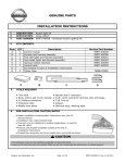
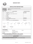
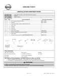
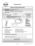
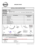
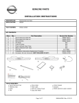
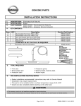
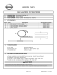
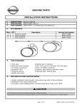
GENUINE PARTS INSTALLATION INSTRUCTIONS DESCRIPTION: APPLICATION: Stainless Steel Illuminated Kick Plate (IKP) INFINITI Q50 PART NUMBER(S) REQUIRED FOR INSTALLATION: 999G6 J2000 (Kick Plate kit) 999G6 J2550 (Harness kit) - Not Included in 999G6 J2000 (Kick Plate kit) 24271-ZW40A (Foam Patch) - Not Included in 999G6 J2000 (Kick Plate kit) 999Q9-J2002 (Accessory Service Connector) - Not Included in 999G6 J2000 (Kick Plate kit) KIT CONTENTS: 999G6 J2000 (Kick Plate Kit) Item Qty. Part Description A 1 Stainless Steel Illuminated Kick Plate FR RH B 1 Stainless Steel Illuminated Kick Plate FR LH C 1 Stainless Steel Illuminated Kick Plate RR RH D 1 Stainless Steel Illuminated Kick Plate RR LH E 10 Location Clips F 4 Black Urethane Foam Tape G 1 Installation Instructions Replacement Template A B C D Service Part Number 999G6 J2010 999G6 J2020 999G6 J2030 999G6 J2040 15-53 08911 N/A 999V2 AW000 E F G ADDITIONAL SERVICE PARTS NEEDED NOT INCLUDED IN ILLUMINATED KICK PLATE KIT: 999G6 J2550 (HARNESS KIT) - SERVICE PART Item Qty. Part Description Service Part Number AA 1 Wire Harness 999G6 J2500 BB 9 Tie Wrap N/A CC 2 Gray Urethane Foam Tape N/A DD 3 Posi Tap 999M1 VT000 EE 8 Black Urethane Foam Tape N/A AA BB CC DD EE 24271-ZW40A (FOAM PATCH) - SERVICE PART Item Qty. Part Description AAA 1 Black Foam Patch, 150mm x 230mm (NOT INCLUDED IN KIT) Service Part Number 24271-ZW40A AAA 999Q9 J2002 (ACCESSORY SERVICE CONNECTOR) - SERVICE PART Item Qty. Part Description AAAA 1 Accessory Service Connector (NOT INCLUDED IN KIT) Service Part Number 999Q9-J2002 AAAA TOOLS REQUIRED: ● Nylon Trim Removal Tool ● Flashlight ● 50/50 alcohol/water solution ● Wire Cutting Pliers ● Scissors Page 1 of 23 ● Phillips Screwdriver ● Soft Non-linting Towel 999G6-J2000 II 04/17/2014 INSTALLATION PROCEDURE: PRE-INSTALLATION CAUTIONS / NOTES CAUTION ● Dealer Installation Recommended. Instructions refer to Service Manual. ● Please read this instruction carefully before installing this product for correct installation. ● Please DO NOT use or install the part in ways other than what is described in this instruction manual. ● If problem occurs during installation, please contact Nissan dealer where you purchased the product. 1) Apply parking brake 2) Confirm the vehicle is no longer in the default shipping state (Extended Storage Switch Pulled Up and BCM in Transit Mode). Failure to confirm the vehicle has been removed from this state will result in the loss of normal vehicle operation. The confirmation requires two checks: 2a) Locate the Extended Storage Switch in the cabin fuse block. Once located, check that it is in the "Customer" position. See below for reference. 2b) To remove transit mode is by doing as follows: 1. Remove fuse cover lid 2. Push down shorting pin 3. Ign On 2 times to ACCY position To put transit mode back is by doing as follows: 1. Ign Off 2. Remove fuse cover lid 3. Pull up shorting pin 4. Assemble fuse cover lid 5. Ign On 2 times to ACCY position 6. Confirm transit mode condition on meter NOTE: Typical vehicle condition shown above. Switch is easily identifiable by the permanent, push-pull fuse holder. Actual position on the fuse block may vary, vehicle to vehicle. CAUTION ● Make sure the ignition is "OFF" before changing the switch position. Condition Switch Position Vehicle is delivered to the dealer Inventory Condition Technician performs PDI Customer Delivery Return switch to Inventory position after PDI. Customer test drives the vehicle Customer Delivery Return switch to Inventory position after test drive. Vehicle is being stored at the dealer Inventory Condition Vehicle is sold and delivered to customer Customer Delivery Note NOTE: The Extended Storage Switch is only an aid to improve battery life during vehicle storage at the dealer. If the Extended Storage Switch fuse ever needs service after vehicle delivery, discard the Extended Storage Switch and install the correct fuse in its place. 3) 4) 5) 6) Turn ignition switch to "ON" position Record the customer radio presets and other presets as required Preset 1 2 3 4 5 6 Put shift lever in "P" position for A/T and CVT or "1st" for M/T Turn ignition switch to "OFF" position Page 2 of 23 999G6-J2000 II 04/17/2014 INSTALLATION PROCEDURE: PRE-INSTALLATION CAUTIONS / NOTES Fig. 1 7) Disconnect the negative battery terminal. 8) Use seat and floor protection. 9) This part is to be installed at surface temperature of 65-100° F. INSTALLATION OVERVIEW: CAUTION ● Take care not to scratch or damage any component during the removal or re-installation process. ● Trim pieces found to have witness marks or broken clips are not to be reinstalled. 1a) Remove the following vehicle parts in the sequence shown below. Store these re-usable parts in a safe and protected manner. Fig. 2 8 11 10 12 13 9 34 5 32 86 43 1 2 1 11 10 Removal Sequence 1. Outer Kick Plate, RR LH 2. Inner Kick Trim, FR LH 3. Outer Kick Plate, FR LH 4. Dashboard Side Lower Panel LH 5. Outer Kick Plate, RR RH 6. Inner Kick Trim, FR RH 7. Outer Kick Plate, FR RH 8. Instrument Side Finisher RH 9. Cover Instrument Lower RH 10. Glove Box 11. Dashboard Side Lower Panel RH Page 3 of 23 97 6 5 7 999G6-J2000 II 04/17/2014 INSTALLATION OVERVIEW: 1b) Installation Outline Fig. 3 Connect to Accessory Service Connector Wire Harness (AA) Long harness to driver side Short harness to passenger side CAUTION ● Vehicle wiring color description is just for reference. Please refer to vehicle wiring diagram for details. 1c) Mechanization Fig. 4 Connector Page 4 of 23 999G6-J2000 II 04/17/2014 INSTALLATION PROCEDURE: VEHICLE PARTS REMOVAL Fig. 5 FRONT OF VEHICLE Nylon removal tool Outer Kick plate RR LH (1) 2) Outer Kick Plate RR LH (1) removal a) Remove Outer Kick Plate RR LH (1) by pulling straight up to disconnect clips as shown in Fig.5 3) Inner Kick Trim FR LH (2) removal a) Remove Inner Kick Plate FR LH (2) by pulling straight up to disconnect clips as shown in Fig.6 and Fig.7 : Clip Fig. 6 1 A FRONT OF VEHICLE B C D Nylon removal tool 2 Inner Kick Trim FR LH (2) 1 13-16 N-m : Clips Reference 2 to Fig. 6 (Underside of Inner Kick Plate FR LH shown) A B C FRONT OF VEHICLE D Fig. 7 Important: Clips are located at locations labeled; 1, 2, and A thru D in Fig.6 and Fig.7. Note locations and orientations to avoid damage. -PULL CAREFULLY- Remove trim by pulling vertically 4) Outer Kick Plate FR LH (3) removal a) Remove Outer Kick Plate FR LH (3) by pulling straight up to disconnect clips as shown in Fig.8 5) Repeat steps 2) through 4) for RH side of vehicle. Fig. 8 13-16 N-m Outer Kick Plate RR RH (5) Inner Kick Plate FR RH (6) Outer Kick Plate FR RH (7) Nylon removal tool Outer Kick plate FR LH (3) : Clip Page 5 of 23 999G6-J2000 II 04/17/2014 INSTALLATION PROCEDURE: VEHICLE PARTS REMOVAL Fig. 9 6) Instrument Side Finisher RH (8) removal a) Insert a nylon remover tool into lower space. b) Pull the Instrument Side Finisher RH (8) straight out as shown in Fig.9. FRONT OF Nylon Instrument Side 13-16 N-m : Clip Fig. 10 13-16 N-m 7) Cover Instrument Lower RH (9) removal. Pull edge under glove box downward, disengage 3 clips identified in Fig.10 b) Slide the Cover Instrument Lower RH (9) rearward to disengage forward locators c) Remove Cover Instrument Lower Cover (9) as shown Fig.10. a) I-Key Antenna 13-16 N-m Front Sonar Controller NOTE: DO NOT DISCONNECT THE CONNECTORS TO EITHER THE KEY FOB SENSOR OR THE FRONT SONAR CONTROLLER. BOTH UNITS MUST BE REMOVED WITHOUT BEING DISCONNECTED FROM THE HARNESS. : Clip Cover Instrument Lower RH(9) Front Sonar Controller I-Key Antenna Fig. 11 8) a) B A b) B A I-Key Antenna removal. Remove two Philips head screws as shown at (A) in Fig. 11. 9) Leave the connector attached Front Sonar Controller removal. a) Remove two Philips head screws as shown at (B) b) The screws at (B) attach through the other side of the Cover Instrument Lower RH (9) c) Leave the connector attached Cover Instrument Lower RH(9) NOTE: Harness Not Shown for Clarity Page 6 of 23 999G6-J2000 II 04/17/2014 INSTALLATION PROCEDURE: VEHICLE PARTS REMOVAL NOTE: On the passenger side of the vehicle the glove box must be removed before the Dashboard Side Lower Panel is removed. 10) Glove Box (10) removal Fig. 12 a) Remove (7) mounting screws from glove box as shown in Fig.12. b) Pull and remove the glove box. c) Disconnect vehicle connectors as shown in Fig.12. 13-16 N-m Glove box (10) Accessory Service Connector taped to harness : Screw Deck lid release switch connector Glove Box Lamp Connector Glove box upper side Fig. 13 11) FRONT OF VEHICLE 12) : Clip Dashboard Side Lower Panel LH (4) Position "A" Clip Dashboard Side Lower Panel LH (4) removal a) Remove the clip at "Position "A" by unscrewing by hand. b) Remove Dashboard Side Lower panel LH (4) by pulling horizontally to disconnect at clips as shown in Fig.13. Repeat for RH side of vehicle. NOTE: DO NOT TRY TO REMOVE THE DASHBOARD SIDE LOWER PANEL RH (11) BEFORE REMOVING THE GLOVE BOX (10). DOING SO IS LIKELY TO DAMAGE THE ATTACHMENT CLIPS. Driver's Side Shown, Passenger Side the Same Page 7 of 23 999G6-J2000 II 04/17/2014 INSTALLATION PROCEDURE: ACCESSORY SERVICE CONNECTOR (IF NEEDED) Fig. 14 13) Inside the glove box cavity, locate the Pre-Wire Connector on the glove box lamp harness. Carefully cut the tape holding the connector and pull it out away from the harness. NOTE: A previously installed accessory may be present. If so, carefully remove the accessory connector harness from the accessory connector plug before posi-tapping. It is recommended that all posi-tapping be completed before reattaching the accessory connector harness to the plug. 13-16 N-m Fig. 15 14) The Accessory Connector Harness needs to be inserted into a path from Point (A) to Point (C) as shown. A two-step process is recommended to install the harness. 1) Tape the loose wire end of the Accessory Connector Harness to keep the wires rigid. Feed the harness over the Cross Car IP Support Beam so that it comes out at the gap (B) between the HVAC and the Steering Controller. 2) Against the Front-of-Dash, tuck the end of the accessory harness up and over Steering Controller. The taped end of the harness should come out at (C) below. Remove the tape from Step 1. Fig. 16 Tie Wraps (BB) Tie Wraps (BB) NOTE: Some vehicles configuration do not have as many obstacles as shown here. 15) Accessory Service Connector (GG) Page 8 of 23 Plug the Accessory Connector Harness into the vehicle Pre-wire connector on the glove box lamp harness. Secure the Accessory Connector harness to existing vehicle harness locations with two tie wraps (BB) as shown in Fig16. 999G6-J2000 II 04/17/2014 INSTALLATION PROCEDURE: WIRING HARNESS INSTALLATION CAUTION This Accessory Service Connector is for use only with Genuine Nissan (or Infiniti) or Nissan (or Infiniti) approved accessories. Use of this connector with non Genuine Nissan (or Infiniti) or Nissan (or Infiniti) approved accessories or failure to follow the installation instructions for the connector contained in this package may result in damage to the accessory and/or your vehicle. Nissan (or Infiniti) is not liable for loss or damage due to improper installation or the installation of non Genuine or non approved accessories. Fig. 17 IGN 7 8 9 1 2 3 10 11 12 4 5 6 Pin location is referenced looking into the face of connector BATSVR IGN Pin 1 2 3 4 5 6 7 8 9 10 11 12 Refer to the Mechanical Drawing on page 23 for wiring Schematic 999Q9 J2002 Label Color IGN BAT TL_LMP RM_LMP BATSVR WHITE RED PURPLE YELLOW PINK RR_DR_RH RR_DR_LH DR_LK_DR_FL_AS FR_DR_SW_RH FR_DR_SW_LH ACC GND DK BLUE LT BLUE GREY DK GRN LT GRN ORANGE BLACK Note: A previously installed accessory may be present. If so, carefully remove the black foam patch (AAA) then Accessory Service Connector from the vehicle harness before posi-tapping. It is recommended that all posi-tapping be completed before reattaching the Accessory Service Connector to the vehicle harness. Note: Be sure to grab the connector and not the harness when separating the plug from the foam tape. Page 9 of 23 999G6-J2000 II 04/17/2014 POSI-TAP for the Accessory Service Connector ONLY. Fig. 19 1) Tap Accessory service wire. a) Identify and confirm correct wire in the Accessory Service Connector to be tapped. b) Remove cap (slot side) from tap body. c) Slide cap around single accessory wire. d) Position cap 6.35mm(0.25in) away from the heat shrink end of Accessory Service Connector (measurement for first posi-tap installed on the circuit). e) Tighten the tap TIGHT with finger pressure. f) Tighten by another quarter turn. NOTE: Figures are not to scale. 2) Inspect the tap to ensure correct installation. a) Pull on the wire lightly to ensure connection. b) Inspect the tap to ensure correct installation. c) Test the signal to ensure that it is working properly. e) d) c) b) Accessory Service Connector Fig. 20 NOTE: Avoid putting pressure on the vehicle wire and tap for the remainder of the installation. i. Straight and evenly spaced all the way around ii. Tighten and minimize gap (wire jacket should be crushed) Fig. 21 3) e) Insert wire to here c) a) d) f) Tighten Tap accessory wire. a) Remove tap (non-pierce) side from tap. b) Remove the protective stub from the wire. c) Insert wire through the non-pierce side opening. d) Spread the individual strands into fan shape. e) Insert wire into the tap body and ensure that it is all the way in. f) g) Fig. 22 Tighten the tap TIGHT with finger pressure. Tighten by another quarter turn. 4) Confirm the tapped accessory wire. a) Pull on the wire lightly to ensure connection. b) Inspect the tap to ensure correct installation. c) Test the signal to ensure that it is working. 5) Forming strain relief loop (always required) i. Straight and evenly spaced all around ii. Tight and no gap and test the signal Service Connector Harness a) Fig. 23 b) b1) b2) b3) Accessory Harness 50.8mm v c) a) c) Page 10 of 23 Gently bend the end of the pierced wire (where it exits the cap) down towards body of Posi-tap. On the tapped wire of the non-pierce side; starting at point b1), measure 50.8mm (2in) to point b3). Make the first bend of the loop b2), half the distance measured 25.1mm (1in), and up towards the body of the posi-tap, make the second bend of the loop b3) in towards the posi-tap so it can be secured with electrical tape. Secure the pierced wire on the heat shrink side and the tapped wire on the non pierce side to the body of the tap with electrical tape (≥ 2 revolutions). 999G6-J2000 II 04/17/2014 IF securing multiple posi-taps on a single circuit. Fig. 24 b) NOTE: If securing multiple taps to single circuit continue to Step 6, if tapping different circuits repeat steps 1-5 as required, then proceed to step 10 6) Multiple posi-taps on the same wire; first tap a) The first accessory is tapped, relieved and secured as shown in Fig 1 thru 5 (these steps are always the same). b) Measure 25.4mm(1in) from point b) to point c) on the pierced wire. c) At points b) & c), bend the pierced wire gently to form the "staircase" shape. 7) Multiple posi-taps; second accessory. a) Tap second accessory at point b), making sure to preserve "staircase shape". b) After tapping second accessory, form a strain relief loop for the tapped wire on the non-pierce side as shown in Fig c) and detailed in step 5b. 25.4mm c) a) Accessory Fig. 25 a) b) NOTE: Do not secure before reading step 8. Repeat as necessary. Fig.26 a) 8) ≥6.35mm Securing multiple posi-taps on the same circuit a) Secure the pierced and tapped wires from the first posi-tap, along with the tapped wire from the non pierce side of the 2nd posi-tap to the body of the 2nd tap with electrical tape (≥ 2 revolutions). b) Note: Repeat as required Note: No single wire should be posi-tapped more than 4 times to maintain integrity. b) Fig. 27 b) a) c) Secure the tapped wires from the non-pierced sides of each tap to each other with electrical tape (≥ 2 revolutions)at a distance of ≥6.35mm(0.25in) from the head of last posi-tap shown in Fig b). 9) Multiple accessory taps on the same circuit secured. a) The first accessory is tapped, relieved and has the pierced wire on the heat shrink side and the tapped wire on the non-pierce side secured to the first tap as shown in Fig a). b) The second accessory is tapped, relieved and has the pierced wire, the tapped wire on the non-pierce side and the tapped wire from the non-pierce side of the first posi-tap secured to the second tap as shown in Fig b). c) Page 11 of 23 Finally the tapped wires on the non-pierce side of the first and subsequent posi-taps are secured to each other as shown in Fig c). 999G6-J2000 II 04/17/2014 Securing multiple tapped wires together. Fig. 28 Service Connector Harness 10) Multiple accessory taps on different circuits secured together. a) The tapped accessories (with wires already secured to tap bodies) are stacked slightly staggered on top of each other as shown in Fig a). a) 6.35mm b) The tapped wires on the non-pierce side of all the posi-taps are secured to each other with electrical tape (≥ 2 revolutions) at a distance of ≥6.35mm(0.25in) as shown in Fig b). c) The pierced wires of the first and subsequent positaps are secured to each other with electrical tape (≥ 2 revolutions) at a distance of ≥6.35mm(0.25in) as shown in Fig c). 6.35mm a) b) c) Posi-Tap Bundle Fig. 29 11) Place secured Posi-tap bundle on sticky side of black urethane foam patch (AAA), then fold in half as shown in Fig29. 12) Location of Completed Posi-Tap Bundle on the Cover Instrument Lower a) Locate Posi-Tap Bundle as shown in Fig.30 b) Critical requirements: - Maximum Thickness of PosiTap Bundle not to exceed 25mm thick. Black Urethane Foam Patch (AAA) Fig. 30 Front of Vehicle 10mm Minimum Posi-Tap Bundle - Do not install Posi-Tap Bundle rearward of the radius of the Cover Instrument Lower RH (9) Fig.30. Approximate Radius Start Do not install Posi-Tap Cover Instrument Lower (RH) - Bundle closer than 10mm from edge of the Cover Instrument Lower (RH) Fig.30. Page 12 of 23 999G6-J2000 II 04/17/2014 INSTALLATION PROCEDURE: To Accessory Service Connector. WIRING HARNESS INSTALLATION Fig. 31 16) Route wire harness (AA) as shown in Fig.31. 17) Align the connector for right side at about 100mm in front of the first harness protector of vehicle as shown in Fig.32. 18) Secure the separate point of wire harness (AA) to vehicle harness by tie wrap (BB) as shown Fig.33. (1 place) 19) Secure the excessive harness of wire harness (AA) to vehicle harness by tie wrap (BB) as shown Fig.33. (1 place) 20) Route wire harness (AA) and secure to vehicle harness by tie wrap (BB) as shown Fig.34. (1 place) FRONT OF To Driver's side Connector for right Wire harness (AA) FRONT OF VEHICLE Connector for right side Fig. 32 The first harness protector Fig. 33 FRONT OF VEHICLE Tie wrap (BB) Excessive harness Wire harness (AA) Fig. 34 FRONT OF VEHICLE Wire harness (AA) CAUTION Tie wrap (BB) ● Do not attach the harness to sharp metal edge. Page 13 of 23 999G6-J2000 II 04/17/2014 INSTALLATION PROCEDURE: WIRING HARNESS INSTALLATION FRONT OF VEHICLE Fig. 35 21) Route wire harness (AA) on the vehicle floor. Then secure wire harness (AA) to floor by black urethane foam tape (F or EE) as shown in Fig.35 (4 places) . Fig. 36 22) Route wire harness (AA) along vehicle parking brake cable as shown in Fig.36. Secure wire harness (AA) to vehicle brake cable using black urethane tape (F or EE) (3 places), then secure wire harness (AA) to vehicle floor by using black urethane foam tape (F or EE), (1 place) as shown in Fig.36. 23) Route wire harness (AA) along vehicle harness and the connector of wire harness (AA) in front of the first harness protector of vehicle as shown in Fig.37. Then secure wire harness (AA) to vehicle harness by tie wrap (BB) (2 places) . Wire harness (AA) Black urethane foam tape (F or EE) FRONT OF VEHICLE Wire harness (AA) Black urethane foam tape (F or EE) Black urethane foam tape (F or EE) Wire harness (AA) FRONT OF VEHICLE Fig. 37 The first harness protector of vehicle CAUTION Tie wrap (BB) ● Do not attach the harness to sharp metal edge. Page 14 of 23 999G6-J2000 II 04/17/2014 INSTALLATION PROCEDURE: WIRING HARNESS INSTALLATION NOTE: The procedure below show the installation for LH side. Repeat procedure for RH side. Fig. 38 24) Function check a) Connect wire harness (AA) to Illuminated Kick Plate FR LH (B) LED unit wire as shown in Fig.38 (RH side is "A") . Wire harness (AA) b) Connect battery. c) Check function. Confirm RH/LH "INFINITI" text is lit when RH/LH front door is in the open position. Manually engage door switch to verify Illuminated Kick Plate turns OFF as shown in Fig.38. LED unit wire d) If OK, disconnect wire harness (AA) from the lamp unit harness of Illuminated Kick Plate FR LH (B). (RH side is "A"). Illuminated Kick Plate FR LH (B) opposite RH side is (A) e) If NG, check harness routing, connections and LED unit to identify root cause. Repeat steps a) to c) until unit is working properly. f) Disconnect battery as shown in Fig.39. Fig. 39 Page 15 of 23 999G6-J2000 II 04/17/2014 INSTALLATION PROCEDURE: ILLUMINATED KICK PLATE FRONT and REAR INSTALLATION NOTE: The procedure below show the installation for LH side. Repeat procedure for RH side. Fig. 40 25) Remove the front door weather strip as shown in Fig.40. Fig. 41 26) Clean the Illuminated Kick Plate attachment area as shown in Fig.41 with 50/50 alcohol/ water, let dry for 30 seconds. 27) Slide Location Clip (E) into the clip seat of backside of Illuminated Kick Plate FR LH (B) as shown in Fig.42. 28) Remove tape liners from backside of Illuminated Kick Plate FR LH (B) as shown in Fig.42. 29) Align Location Clips (E) on Illuminated Kick Plate FR LH (B) to vehicle holes (first, second & fourth) as shown Weather strip 13-16 N-m FRONT OF VEHICLE FRONT OF VEHICLE 13-16 N-m Illuminated Kick Plate attachment area Fig. 42 13-16 N-m Location Clips (E) Tape's liner Illuminated Kick Plate FR LH (B) FRONT OF VEHICLE Fig. 43 Illuminated Kick Plate FR LH (B) in Fig.43. Vehicle holes for clips Page 16 of 23 999G6-J2000 II 04/17/2014 INSTALLATION PROCEDURE: ILLUMINATED KICK PLATE FRONT and REAR INSTALLATION NOTE: The procedure below shows the installation for LH side. Repeat procedure for RH side. FRONT OF VEHICLE Fig. 44 13-16 N-m 30) Insert clips to vehicle holes and push down to lock clips. 31) Apply minimum 11lb (49N) of pressure along the part to attach tape to body as shown in Fig.44. CAUTION ● Use caution when applying pressure as the surface may dent. ● During installation, be careful not to allow the harness to get stuck between the vehicle and the kick plate. Illuminated Kick Plate FR LH (B) 13-16 N-m FRONT OF VEHICLE Fig.45 32) Clean the Illuminated Kick Plate attachment area as shown in Fig.45 with 50/50 alcohol/ water, let dry for 30 seconds. 33) Slide Location Clip (E) into the clip seat of backside of Illuminated Kick Plate RR LH (D) as shown in Fig.46. Illuminated Kick Plate attachment area 13-16 N-m Fig. 46 Location Clips (E) 13-16 N-m Illuminated Kick Plate RR LH (D) Page 17 of 23 999G6-J2000 II 04/17/2014 INSTALLATION PROCEDURE: ILLUMINATED KICK PLATE FRONT and REAR INSTALLATION NOTE: The procedure below show the installation for LH side. Repeat procedure for RH side. FRONT OF VEHICLE Fig. 47 34) Align Location Clips on part to first and second holes on vehicle from front side as shown in Fig.47. Fig. 48 35) Insert Location Clips to vehicle hole and push down to lock clips as shown in Fig.48. Illuminated Kick Plate RR LH (D) 13-16 N-m Vehicle holes for clips FRONT OF VEHICLE CAUTION Illuminated Kick Plate RR LH (D) 13-16 N-m ● Use caution when applying pressure as the surface may dent. ` 13-16 N-m Page 18 of 23 999G6-J2000 II 04/17/2014 INSTALLATION PROCEDURE: HARNESS CONNECTION INSTALLATION NOTE: The procedure below show the installation for LH side. Repeat procedure for RH side. Fig. 49 Black urethane foam tape (F or EE) attachment area 36) 1cm min. ref. Clean both sides of the attachment area for the black urethane foam tape (F or EE) with 50/50 alcohol & water, let dry for 30 seconds as shown in Fig.49. NOTE: Confirm the LED unit wire is a minimum of 1cm from the vehicle harness protector on both sides of the vehicle as shown in Fig.49 Illuminated Kick Plate FR LH (B) Fig. 50 37) LED unit wire 13-16 N-m Black urethane foam tape (F or EE) Place black urethane foam tape (F or EE) over flange, then place the LED unit wire on top of the black urethane foam tape (F or EE) as shown in Fig.50. Apply second black urethane foam tape (F or EE) on top of the LED unit wire as shown in Fig.50. Black urethane foam tape (F or EE) VIEW A LED Unit Wire Vehicle Panel of Flange VIEW A OK LED Unit Wire Not Good CAUTION: BE CAREFUL NOT TO LET THE IKP WIRING INTERFERE WITH THE INNER KICK TRIM ATTACHMENT FEATURE ON ANY OF THE HARNESS PROTECTORS. DOING SO COULD RESULT IN DAMAGED CLIPS, IMPROPER ATTACHMENT AND POSSIBLE BUZZ, SQUEAK, AND RATTLE ISSUES FOR THE CUSTOMER. Vehicle harness protector Page 19 of 23 999G6-J2000 II 04/17/2014 INSTALLATION PROCEDURE: HARNESS CONNECTION INSTALLATION NOTE: The procedure below show the installation for LH side. Repeat procedure for RH side. Fig. 51 FRONT OF VEHICLE 38) Harness protector Route LED unit wire of Illuminated Kick Plate FR LH (B) into harness protector as shown in Fig.51. CAUTION LED unit wire ● Do not attach the harness to sharp metal edge. Illuminated Kick Plate FR LH (B) Fig. 52 39) Connect LED unit wire (B) to wire harness (AA) then cut one piece of gray urethane foam tape (CC) in half, apply one half around connecting section as shown in Fig.52. Use other half piece of gray urethane foam tape (CC) for RH side. 40) Secure the connector of wire harness (AA) and LED unit wire (A) & (B) Wire Harness (AA) Gray urethane foam tape (CC) Fig. 53 Connector 13-16 N-m and Excessive harness FRONT OF VEHICLE excessive harness to vehicle harness with tie wrap (BB) as shown in Fig.53. CAUTION ● Do not attach the harness to sharp metal edge. Tie wrap (BB) Wire harness (AA) Page 20 of 23 999G6-J2000 II 04/17/2014 ACCESSORY CHECK: (Must for any accessory that uses the vehicle battery for power) Connect the battery negative terminal and tighten the nut to 5.4 N-m (47.8 lb-in) Check all Critical Installation Steps. Check all torque values. (Reference related steps and figures) Verify all wiring is secure and not exposed. Trim all excess tie wraps flush. Check function. Confirm RH/LH "INFINITI" text is Illuminated when RH/LH front door is in the open position. Manually engage door switch to verify Illuminated Kick Plate turns OFF when door closes. Check all vehicle electrical systems that the accessory interfaces with. Vehicle electrical system 1 (Must for pre-wiring, overlay harness, and Posi-Tap) Vehicle electrical system 2 (Electrical system(s) that the accessory connects to) RE-INSTALLATION OF REMOVED PARTS: CAUTION Use caution when re-installing interior components to avoid damage, scratches, or breaking of mounting clips. Refer to the vehicle service manual for more information. Re-install all removed vehicle parts. Refer to the vehicle service manual as necessary. IMPORTANT : Do not reinstall the Glove Box (10) until after the Dashboard Side Lower Panel RH (11) has been installed Reinstall the Dashboard Side Lower Panel LH (4) and RH (11). Be very careful not to damage the clips while inserting in the A-Pillar. (See Fig.A below) Reinstall both the Inner (2 & (6) Kick Trim being very careful that the vertical oriented tabs are aligned with the clips on the wire harness retainers. (See Fig.6 & Fig.7, pg 5) Reinstall the Glove Box (10) Make sure that all four of the U-clips along the top of the glove box opening are present. Reconnect the Deck Lid Release Switch, Glove Box Lamp and seat the harness clip to the top of the glove box. Reinstall the glove box, being careful not to trap any wiring. Reinstall Sill Kick Trim vertically being very careful that all clips engage correctly. Harness Protector (Typ.) 3 clips on each side Clip Locations Dashboard Side Lower Panel LH Fig. A Fig. B LH A-Pillar Lower Shown Page 21 of 23 999G6-J2000 II 04/17/2014 FINAL INSPECTION: Clean interior of vehicle. Verify re-installed trim parts for proper flush fit (no gap, no waviness, etc.). Verify all clips are fully engaged and locked. Verify re-installed trim parts are free from cracks, scratches or stress marks. Verify vehicle headliner, seat, steering wheel, center console, floor carpets, etc. are not soiled. Verify interior and exterior is not damaged. Turn ignition switch to "ON" and confirm proper operation of vehicle systems If equipped, verify all window and sunroof one touch operation and perform the reset procedure if necessary. Refer to the vehicle service manual for more details. Trunk Release Connector - Turn on the car, push and note if trunk opens. Glove Box Lamp - Turn on headlamps; open glove box and note whether light goes on. Room Lamp - Open door and note whether light goes on. (Be sure that room lamp switch for on when door open is "on") Key FOB Sensor - Place key FOB as shown below. And start vehicle. Note whether vehicle starts. Dashboard Side Lower Panel RH (10) Glove Box Lower Cover (12) Front Sonar Module Connector - Turn on vehicle, put vehicle in 'Drive'. Move slowly towards a large object in front of the vehicle. Note whether alarm sounds. Start engine and verify that there are no new Diagnostic Trouble Codes. Turn ignition switch to "OFF". Place the Owner Manual, Quick Reference Guide, and/or other Manuals in the glove box. If this vehicle will be returned to a dealer lot or showroom, always place the extended storage switch in the "inventory" position. Refer to the Extended Storage Switch verbiage at the beginning of the 'INSTALLATION PROCEDURE' section. Re-program radio presets and other vehicle settings to the recorded settings. No need to do this step if the extended storage switch is placed in the "inventory" position. CAUTION ● Do NOT step on kick plate or wash vehicle for 24 hours after installing to prevent the double-sided tape from peeling. NOTE: Posi-TapTM is protected by patent # 5,228,875 5,695,369 5,868,589 6,692,313 Jap 2881414 Aus 708700 Tia 103534 Can 2204826 Mex 200626 Korea 477279 China Z197105562.9 & others pending. Page 22 of 23 999G6-J2000 II 04/17/2014 Mech Drawing ILLUMINATED KICK PLATE KIT ACCY_SER_CONN RED WHT IGN 1 RED BAT 2 PURP TAIL_LAMP 3 YEL ROOM_LAMP 4 PNK 5 BAT_SAVER BLU RR_DOOR_RH 6 LT_BLU RR_DOOR_LH 7 GRY DR_LK_DR_FL_AS 8 GRN FR_DOOR_SW_RH 9 LT_GRN FR_DOOR_SW_LH 10 ORG 11 ACC BLK GND 12 PASSENGER SIDE CONNECTOR TH12MW-NH 4 5 6 7 8 9 10 11 12 Note: Pin location is referenced looking into wire side of connector. BLK 3 WHT 2 RED 1 ILLUMINATED KICK PLATE RH RED BLK ILLUMINATED KICK PLATE LH RED BLK Legend Posi tap Gray Red Page 23 of 23 999G6-J2000 II 04/17/2014


![Hospice Technical Questions & Answers [PDF 114 KB]](http://vs1.manualzilla.com/store/data/005731144_1-513883a519d0031f5bbd9acf18f18865-150x150.png)