1
D3, D5 and A10 User guide
TM
TM
TM
DOMESTIC AND
INDUSTRIAL
SLIDING GATE
OPERATORS
Product Guarantee D3 and D5
The CENTSYS D3 and D5 Version 3 sliding gate operators are manufactured with extreme care,
thoroughly inspected and tested. The operators are only guaranteed against faulty materials or
workmanship for a period of 24 months from the invoice date of the operator, or 26 months from the
manufacturing date (as shown on the serial number label of the operator), whichever expires first.
The guarantee will cover the repair or replacement at our discretion of such faulty materials or parts
free of charge, provided that the equipment is returned to our workshop.
The guarantee only applies to the gearbox, motor, controller and other components specific to the
operator. Peripheral components such as the charger, battery and other ancillary devices connected
to the operator carry the guarantee provided for these components.
This guarantee will not apply to any operator which:
a. Has been subject to misuse or which has been used for any purpose other than
designed for by Centurion Systems (Pty) Ltd
b. Has not been installed in accordance with the installation instructions provided.
c. Has damage caused as a result of handling during transit, atmospheric conditions,
insect infestation, power surges or other forces outside of our control
d. Has been repaired by any workshop and/or person NOT previously authorised by
Centurion Systems (Pty) Ltd
e. Has been repaired with components not previously tested, passed or authorised by
Centurion Systems (Pty) Ltd
Product Guarantee A10
All CENTSYS products are manufactured with extreme care, thoroughly inspected and tested. The
products are only guaranteed against faulty materials or workmanship for a period of 12 months
from the invoice date of the product, or 14 months from the manufacturing date (as shown on the
serial number label of the operator), whichever expires first.
The guarantee will cover the repair or replacement at our discretion of such faulty materials or parts
free of charge provided that the equipment is returned to our workshop.
This guarantee will not apply to any equipment which:
a. Has been subject to misuse or which has been used for any purpose other than
designed for by the manufacturers.
b. Has not been installed in accordance with the installation instructions provided.
c. Has damage caused as a result of handling during transit, atmospheric conditions,
insect infestation, power surges or other forces outside our control.
d. Has been repaired by any workshop and/or person NOT previously authorised by
Centurion Systems (Pty) Ltd
e. Has been repaired with components not previously tested, passed or authorised by
Centurion Systems (Pty) Ltd
Page 2
Company Profile
Centurion Systems (Pty) Ltd, South Africa, has been manufacturing automatic gate systems since 1986,
and is committed to providing reliable, cost effective solutions in the field of gate and access
automation.
We offer a diverse range of products including gate motors, GSM-based products, garage door motors,
remote controls, keypads, traffic barriers, proximity access control and intercom systems.
Our products are developed by an in-house team of talented engineers that are constantly researching
new and innovative technologies to improve our existing products and expand our product range.
Our production facility in Johannesburg is ISO:9001 quality assurance certified, and all our products are
manufactured to the highest level of quality with a 100% test to specification.
Through a team of dedicated technicians and sales personnel, together with a fully fledged in-house
training facility, we are committed to providing unmatched service to our customers and support for our
products.
A worldwide network of distributors and installers ensure that our products remain The Automatic
Choice in access automation .
Further information is available on our website www.centsys.com.au
© CENTURION SYSTEMS (PTY) LTD 2005
Centurion Systems (Pty) Ltd reserves the right to make changes to the products described in this document without notice and without
obligation of Centurion Systems (Pty) Ltd to notify any persons of any such revisions or changes. Additionally, Centurion Systems (Pty) Ltd
makes no representations or warranties with respect to this document.
No part of this document may be copied, stored in a retrieval system or transmitted in any form or by any means electronic, mechanical,
optical or photographic, without the express prior written consent of Centurion Systems (Pty) Ltd.
Page 3
Table of Contents
Introduction ...........................................................................................................................................
6
6
Models covered ....................................................................................................................................
6
6
Main features ........................................................................................................................................
6
6
Normal operation ..................................................................................................................................
8
8
Radio transmitter .....................................................................................
8
8
Intercom pushbutton ...............................................................................
8
8
Pedestrian keyswitch ...............................................................................
9
9
Controller features and functions ..........................................................................................................
10 10
Introduction ..............................................................................................
10 10
Anti-crushing device ..............................................................................
10 10
Automatic alignment ...............................................................................
11 11
Automatic closing ....................................................................................11
11
Autoclose override .................................................................................11
11
Mains failure detection ..........................................................................
12 12
Battery low protection ...........................................................................
12 12
Thermal overload ...................................................................................
12 12
Origin sensor fail ...................................................................................
13 13
Lightning protection ...............................................................................
13 13
Ancillary equipment ..............................................................................................................................
13 13
Protection beam ......................................................................................
13 13
Holiday lockout ......................................................................................
14 14
Courtesy light timer ..............................................................................
14 14
Pre-flashing .............................................................................................
14 14
Gate status indication .............................................................................
15 15
Solar panel ...............................................................................................
15 15
DC Converter module ..............................................................................
16 16
Reversing mode .......................................................................................
18 18
Condominium ..........................................................................................
18 18
Passive infraRed Autoclose (PIRAC) ...................................................1818
Manual release .....................................................................................................................................
19 19
Re-engaging the manual release ..........................................................
20 20
Page 4
20
Basic maintenance .................................................................................................................................
20
20
General .....................................................................................................
20
21
Battery .......................................................................................................
21
21
Gearbox oil level ......................................................................................21
21
Power supply ............................................................................................
21
22
A10 Inverter module ..................................................................................
22
23
Specifications .........................................................................................................................................
23
D3/D5 Operator ........................................................................................23
23
A10 Operator .............................................................................................24
24
A10 DC Converter .....................................................................................
24
24
Optional extras ......................................................................................................................................
25
25
Declaration of Conformity .......................................................................................................................26
26
Commissioning check sheet ........................................................................................................
27 & 28
Page 5
Introduction
This guide highlights the features and operation of CENTSYS SLIDING GATE
OPERATORS to ensure that you, the user, get the most from your system. Basic
maintenance is also described, but in the event of product malfunction, you are
advised to contact your installer, or your local Centurion Systems (Pty) Ltd outlet
(refer to back page).
Models covered
!
!
!
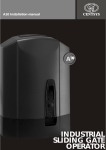
CENTSYS D3 sliding gate operator
CENTSYS D5 sliding gate operator
CENTSYS A10 sliding gate operator
Main features
D3 and D5
A key feature of these products is the chassis/gearbox which is moulded from a
high-tech engineering polymer. The user benefits from this material in terms of its
aesthetics, and corrosion-free properties. Due to the self-locking action of the
internal gearset, the unit is resistant to forced entry.
An optional theft-resistant cage is available to give additional peace of mind.
A revolutionary aspect of the CENTSYS range of operators is the limit switch
mechanism. Mounted internally, and therefore tamper proof, the limit switch
monitors the speed and location of the gate, ensuring reliable and safe anti-crushing
protection and accurate position control.
Precise control of the gate stopping position is achieved by a high resolution
encoder wheel and opto-electronic sensor built into the unit.
The electronic controller has many advanced features including variable sensitivity
collision detection, adjustable delay Autoclose, pedestrian opening, etc.
Advanced lightning protection is built into the controller as standard. On the D3 and
D5 domestic models, a 12V battery is the primary power source, thus providing a
limited number of operations in the event of a mains power failure.
This battery is normally charged by an internal 220V* charger. For sites where a 220240V mains supply is unavailable, an external 220-12V adaptor, or solar panel is
Page 6
optional (see SOLAR PANEL, page 17 for more details about solar charging).
In multi-user applications the D5 operator is available with a transformer rectifier unit
(power-pack), which replaces the battery and charger. The power pack operates
directly off a 220V* mains supply only. Battery backup is available by simply adding
an externally mounted battery.
*Alternative voltage ratings are available on request
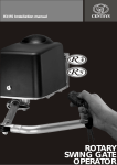
A10
Engineered for industrial and high-duty sites, the A10 is built around a precisionmachined, die-cast aluminium chassis/gearbox incorporating a self-locking gearset.
Accordingly, the unit is resistant to forced entry.
The integral electronic controller has similar functions to those of the D3 or D5 and
uses the same technology in terms of origin and encoder signal inputs. Unique to the
A10 is the high speed mode, enabling adjustable opening and closing speeds up to
30 metres per minute.
The key to the A10’s outstanding torque and duty cycle lies in the three-phase
induction motor and electronic inverter that form the heart of the system. Singlephase 220-240V AC power is converted into variable frequency three-phase power,
allowing electronically controlled soft starting and stopping of the motor.
An optional DC converter is available, containing 12V batteries and UPS type backup
circuits. This enables the A10 to continue operating for a limited period in the event of
a power failure. Another option is the theft-resistant cage, to give additional peace of
mind.
“Endurance” and “Heavy Duty” derivatives of the A10 are available to suit high duty,
and high gate mass sites respectively.
Page 7
Normal operation
The gates can be opened or closed in the following way:
Radio transmitter
A handheld radio transmitter, carried in the motor car, sends a coded signal to the
receiver mounted in the control enclosure to open or close the gate.
A10
Press once for approximately one second to initiate gate motion.
If the transmitter is pressed while the gate is either opening or closing the gate will
immediately stop. Pressing the button again will cause the gate to reverse.
If the automatic closing feature (see Controller Features and Functions) has been
selected and the gate is closing automatically when the transmitter is pressed, the
gate will stop and stay in that position. Pressing the button again will cause the gate to
re-open. If the gate is opening with the automatic closing facility selected, and the
transmitter is then pressed, the gate will stop. The gate will close automatically after
the Autoclose delay time.
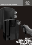
Intercom pushbutton
PRESS TO
OPEN GATE
Visitor outside gate requests entrance.
Gate opened from intercom
pushbutton inside house.
Page 8
Most automatic gate installations are fitted with an intercom which provides for
communication between the house and the gate.
The intercom handset is usually provided with a “Gate" or "Door Release”
pushbutton which, when pressed, sends a signal to the gate controller to open the
gate.
The sequence of operation of this pushbutton is identical to the radio transmitter
described under “Radio Transmitter”.
Pedestrian keyswitch (optional)
The pedestrian keyswitch is fitted to the gate pillar. It’s purpose is to open the gate a
limited amount for pedestrians.
! Fit the key into the keyswitch and
turn the key clockwise as though
starting a motor car.
! Let key spring back to rest position
and remove key immediately.
To allow time for removal of the key,
there is a five second delay before the
gate begins to open. If the courtesy light
is connected to the control card it will
flash five times, indicating that the
signal has been accepted.
The gate will open approximately one metre and then stop. After five seconds the
gate will automatically close.
The gate can be held open by keeping the key turned in the keyswitch. As soon as
the key is released back to its normal rest position, the gate will close after the five
second delay. (The opening distance and the time that the gate remains open can be
adjusted to suit. Default values are described above).
If a protection beam has been fitted (refer section “Protection Beams”) and the beam
is broken while the gate is closing, the gate will stop. The gate will remain in that
position while the beam is broken and only close five seconds after the beam has
been cleared.
Page 9
Controller features and functions
Introduction
The electronic controller synchronizes the functions of the gate operator. Although
the controllers for each operator are marginally different, the functions and safety
features which are described below are similar.
Anti-crushing device
Gate closing
Gate closing into an obstruction
Gate automatically reverses and re-opens
Gate opening
STOP
Gate opening
Gate stops on hitting the obstruction
If the gate is obstructed repeatedly four times, either opening or closing, often referred
to as multiple collision, the gate will stop and will not respond to trigger inputs for two
minutes.
After this time the gate will once again respond to command signals. This function is a
warning to the user that the obstruction must be removed. (The number of obstructions before the system will shut down can be adjusted to suit, default is four).
Page 10
Automatic alignment
CENTSYS operators are fitted with a manual override mechanism. This is to allow the
gate to be operated in the event of a total malfunction of the equipment. It is also
required if the mains power has failed in the case of the 220V operators ( A10 models).
When a command signal is given after the gate has been moved manually and then reengaged, the gate will drive to either it’s fully open, or closed, position. Referred to as
automatic alignment, the gate can only be stopped, but not reversed until the alignment cycle is complete. The system will then revert to normal operation.
Automatic closing (optional)
The system has the facility to automatically close the gate after it has been opened.
The default setting is that this facility is disabled. The time that the gate remains open
can be adjusted up to four minutes where the default is 15 seconds.
Autoclose override
The Autoclose function can be temporarily overridden by holding down the remote
control pushbutton or intercom gate release when opening the gate, until the gate
stops. (Default setting is three seconds. It can be changed to suit.) This confirms
that the Autoclose has been overridden. On releasing the button, the gate will
continue to open fully, and remain open as long as required.
INTERCOM PUSHBUTTON or REMOTE
PRESS and HOLD GATE RELEASE
FOR THREE SECONDS TO
OVERRIDE AUTOCLOSE
Closing the gate by using either the transmitter or intercom gate release button
resets the system back to Autoclose.
Page 11
If a gate status indicator (LED) has been fitted inside the house, an additional
confirmation of the functioning of the override is provided. The status LED will
stop flashing and remain ON when the Autoclose has been overridden.
Mains failure detection (D3/D5 only)
Although these systems will continue to operate in the event of a mains power failure
due to the built-in battery, it is important to register that there is a problem before the
battery is run flat.
The controller (CP80) monitors whether mains voltage (via the charger transformer)
is present. If not, the gate status LED, will flash twice every two seconds to indicate
mains loss.
Battery low protection (D3/D5 only)
The controller has circuitry that monitors the state of the battery. During a power
failure energy is drawn from the battery, but not replaced. To prevent the battery
running flat and being damaged, the protection circuitry shuts off the gate system
when the battery voltage drops below 10.6V.
NOTE: - LED WILL FLASH THREE TIMES
EVERY TWO SECONDS TO INDICATE
BATTERY VOLTAGE IS LOW
- D3/D5 OPERATOR PCB SHOWN
RED LED
If the gate status
indicator has not been
fitted inside the house,
there is an equivalent LED
mounted on the controller
marked “STATUS”
STATUS
Thermal overload (A10 only)
In the event of the A10 operator being used excessively and the duty cycle rating of
the unit exceeded, the unit will shut down due to thermal overload in order to protect
the system from abuse.
The unit cannot be re-operated until the unit has cooled. To provide indication to the
user that this is the cause of the fault the status LED will flash twice every two seconds.
Page 12
Origin sensor fail (A10 only)
The A10 operator uses an origin switch to ensure it stops in the correct open and
closed positions. If this switch fails for any reason, the operator will shut down. To
provide indication to the user that there has been an origin sensor failure, the
status LED will flash three times every two seconds.
This condition is treated as serious and the unit cannot be activated again until the
gate has been moved manually either fully-open or fully-closed, ensuring that the
gate magnet has passed the sensor. If the sensor registers correctly, the unit will
reset, and can be operated again. If the sensor does not re-register, the unit will
remain in the locked state.
If the system cannot be reset by following the procedure above, it is a clear
indication that the SENSOR is faulty or not switching reliably. It is important that
the operation of the SENSOR is checked by a qualified technician.
Lightning protection
All CENTSYS controllers have onboard lightning protection. The protection circuitry
was designed in conjunction with the CSIR. Provided that the system has been
properly earthed the protection will significantly improve the resistance of the
system against lightning strikes.
Ancillary equipment
Protection beams (optional, but recommended)
An infrared beam, or underground loop across the gate entrance may be connected
to the controller as an additional safety feature. When a motor vehicle activates the
loop or beam the following occurs:
! If the gate is closing, it will immediately stop and reopen
! If the transmitter or intercom gate release pushbutton is pressed while the beam
is broken, or the loop activated, the gate will remain open. The Autoclose time will
restart its countdown
Page 13
Holiday lockout (optional)
A keyswitch can be connected to the gate system that will allow the system to be
totally immobilised. The keyswitch is mounted with access from the outside of the
property. When the keyswitch is OFF, the gate system will shut down and it will not
be possible to operate the gate. When the keyswitch is ON, the gate system will
operate normally.
This is an added security feature should the property be unattended for an
extended length of time.
The Holiday Lock out facility could also be activated using a keypad, radio receiver
with a latching output or an ON/OFF toggle switch.
Courtesy light timer (optional)
If a 220V power supply is available at the gate, timed courtesy lights can be
connected through the controller. Each time the gate is opened, the lights will
switch on for a period of time and switch off. The time can be adjusted up to forty
minutes in ten second increments.
A courtesy light pushbutton can be mounted inside the house (typically on the
intercom) allowing convenient control of the lights. By pressing the pushbutton.
By pressing the courtesy light pushbutton (if fitted), momentarily the light will switch
on for the light timer period and automatically switch off. By pressing and holding
the pushbutton down for three seconds the lights will switch on and remain on. The
status LED (if fitted) will flash once every two seconds to confirm this. To switch off
the lights, press the pushbutton momentarily. If courtesy lights are fitted to the
controller, and the pedestrian keyswitch is operated, the courtesy lights will flash for
five seconds before the gate opens. This warns the pedestrian that the gate will
open within five seconds allowing time to remove the key and stand back from the
gate.
Pre-flashing
The courtesy light can be programmed to flash for a period of time before the gate
starts to open or close. The courtesy light timer will function as normal. (Pre-flash
time can be adjusted to suit, from 1 to 250 seconds, where the default is five
seconds). By default pre-flashing is off.
Page 14
Gate status indication (optional)
The controller can provide visual indication inside the house of the position of the
gate and the condition of the battery and power supply. An LED is typically mounted
on the intercom inside the house. The different signals of the LED are shown in the
following table:
LED STATUS
INDICATION
Slow regular flash
Gate is opening
Quick regular flash
Gate is closing
Off
Gate is closed
On
Gate is open
1 Flash/2 seconds
Courtesy light switched on (see
Courtesy Light Timer, page 15)
2 Flashes/2 seconds Mains failure (D3/D5 only. See Mains
Failure Detection, page 13)
Or:
Over temperature (A10 only. See
Thermal Overload, page 14)
3 Flashes/2 seconds Battery low (D3/D5 only. See Battery
LowProtection, page 13)
Or:
Missed origin (A10 only. See
Origin Sensor Fail, page 14)
4 Flashes/2 seconds Collision shutdown
(See Anti-crushing Device, page 11)
Page 15
Solar panel (optional on
D3/D5 systems only)
The battery of the 12V DC operator may be
charged using a solar panel in place of the
conventional charging circuit. A 12 Watt
panel will provide on average 10 - 12
operations of an average gate without
causing the battery to discharge over a
period of time.
SOLAR
PANEL
It is necessary to have at least a 35Ah deep cycle low-maintenance battery fitted, in
order to provide sufficient backup capacity during days of poor weather.
For further details contact your local CENTSYS agent.
DC Converter module (optional for A10 only)
The DC converter module allows the A10 gate operator to function from a 12V battery
in the absence of AC mains. The converter module steps up the 12V battery supply to
310V DC. The inverter drive on the A10 operator then switches the high voltage DC
supply to run the three-phase induction motor.
WARNING The 310V DC supply is hazardous and potentially lethal.
The A10 DC converter module should be installed and
maintained by a qualified installer.
The following features are of interest:
The converter module includes battery protection circuitry. This circuitry prevents the
converter module from being damaged in the event of reverse polarity connection. In
addition the circuitry automatically disconnects the battery when the battery drops
into a low-voltage state. This prevents the converter module from running the battery
flat and potentially damaging the battery.
There is a pushbutton on the converter module that manually reconnects the battery
in the event of a power failure and low battery voltage state.
Upon activation, and if the battery voltage exceeds the low-voltage parameter, the
protection circuitry will automatically keep the battery connected to the converter. If,
on the other hand, the battery voltage is below the low-voltage parameter, the
Page 16
protection circuitry will not connect the battery to the converter.
The DC Converter module has three status LEDs. These LEDs indicate battery
status, AC mains status, and lastly the temperature of the converter. The LEDs
operate in the following manner:
LED
When ON,
it indicates:
Logic
When OFF,
it indicates:
Battery
status
Battery is
fully charged
Voltage
low
AC Mains
Mains
present
Mains
failure
Converter
temperature
Overheated
DC converter will
shut down until it
has cooled to
normal operating
temperature range
Logic
DC converter will
shut down until
battery reaches
normal operating
voltage.
DC converter will
power A10 until
mains restored or
battery voltage <
threshold.
Converter
temperature
normal
The converter module has a current limiting fuse on the high-voltage supply. Caution
must be exercised when checking this fuse.
The procedure to replace the fuse is outlined below:
1. Disconnect the mains from the entire system. This includes the A10, and
the converter module
2. Disconnect the battery
3. Disconnect the six-way header that connects the converter module to the
A10. The converter module is now off, and the board is safe to handle
4. Remove the fuse protection housing (If the housing is still in place)
5. Remove the fuse and replace it with a 5A, 250V, fast-blow fuse. (Dimensions
5mm x 20mm)
6. Reconnect the six-way header
7. Reconnect the battery
8. Reconnect the mains
Upon reconnecting, if the converter module fails to function correctly in the event of
a power failure, refer to an installer or service technician.
Page 17
Special Functions
Reversing Mode
Apart from the Standard Mode of Operation as described in the section Normal
Operation, the system offers another Mode of Operation. Referred to as Reversing
Mode, if the transmitter is pressed while the gate is moving, the gate will automatically reverse direction. The gate can never be left in mid position with this mode
selected.
Other Modes of Operation which can be selected and operated using a radio
transmitter are CONDOMINIUM and PIRAC, which are described below.
Condominium
The system can be programmed for “Condominium” operation. This Mode of
Operation will override the normal Mode of Operation described under the section
“Normal Operation”. This facility is designed for greater safety and security in
applications where there will be a number of users, such as the gate at a townhouse
estate, factory or office park the “Autoclose” facility described earlier.
In “Condominium” mode “Autoclose” cannot be overridden. If the remote control or
intercom pushbutton is pressed while the gate is open the “Autoclose” will restart its
countdown. If the gate is activated while the gate is closing the gate will reopen. The
gate cannot be stopped in a midway position and will therefore always close.
A protection beam should be used in conjunction with this facility to prevent the
“Autoclose” from closing the gate onto a vehicle passing through.
Passive Infrared Autoclose (PIRAC)
This facility is an extension of the Condominium facility described above. It is
designed for applications requiring greater security as the gate closes immediately
behind the vehicle or person passing through.
PIRAC will operate only if a protection beam or other type of vehicle detection system
(e.g. Inductive loop) has been fitted.
The remote control or intercom pushbutton will only open the gate. As a vehicle
drives through the entrance it activates the protection beam and as soon as the
vehicle clears the beam the gate will close immediately, even before it is fully open. If
the gate reaches the fully open position without the beam being activated the gate
will close immediately.
In this mode and for a particular application should the gate start to close too quickly
Page 18
the "Autoclose" facility described earlier can be enabled.
The gate will now remain in the open position until either the "Autoclose" facility has
timed out, or a vehicle has driven through the entrance, in which case the gate will
start to close immediately the vehicle has passed.
Manual release
All operators are fitted with a manual release mechanism. This is to allow the gate to
be operated in the event of a total malfunction of the equipment. It is also required if
the mains power has failed in the case of the A10 (without DC converter) operator.
CENTSYS D3 and D5
Open manual override
Rotate thumbwheel clockwise
until gate is free to move
CENTSYS A10
A10
Manual release
handle in closed position.
A10
Open lock cover and insert key.
Turn key ¼ turn counter
clockwise to unlock.
Page 19
Pull manual release handle
down to disengage manual
release
Re-engaging the manual release (A10 only)
It is strongly recommended that the gate is first pushed to the fully open
position, and then to the fully closed position before the release handle is reengaged. This is to ensure that no untoward behavior occurs due to the
system having lost its position information.
Basic maintenance
CENTSYS operators are designed to be maintenance-free. However, there are
some basic checks that should be carried out regularly (every six months). These
will increase the long term reliability of the system, and obviate false triggering of the
protection systems leading to erratic operation of the gate.
Isolate mains supply to system before cleaning or working on the equipment.
General
! Keep the track clear of stones, dirt and
obstructions.
! Ensure that all rollers are free.
! In manual mode check that the gate runs
freely on its rail and does not catch or foul
against the walls or pillars.
! Ensure that the gate wheels and guide
rollers are rotating freely and are not worn. In
high volume applications it will be necessary
to replace these components regularly.
! Ensure that the rack is properly secured
to the gate and that it does not press down
onto the operator pinion at any point along its travel.
! Keep shrubs and vegetation clear of the motor, rack or chain.
! Check that the key still operates the manual override access door or flap. Spray
with oil if necessary.
! Keep the inside of the motor housing clear of insects and dust.
! On operators fitted with a cooling fan, check that the air inlet ducts in the cover
and the outlet ducts in the gearbox are clear.
Page 20
The battery (D3/D5 Operators only)
CENTSYS systems that are fitted with maintenance-free lead-acid batteries, should
provide at least three years of normal service life.
For sites utilizing an external 35Ah battery, ensure that the level of liquid (electrolyte
level) is correct. Check for corrosion of the battery terminals. Clean and apply copper
based grease as necessary.
WARNING Ensure that the enclosure which houses the 35Ah
battery can adequately vent any battery gases
generated.
Gearbox oil level
Check the oil level as described in the section, Lubrication, of the Installation Manual.
Should the installation manual be unavailable, please refer to the Online Manuals on
our website, www.centsys.com.au. Alternatively, please contact your CENTSYS
installer.
Power Supply
All Centurion Systems (Pty) Ltd operators have power supplies separate to the
controllers. In the case of product malfunction, the power supply fuses should be
checked.
GREEN LED
CHARGE/POWER
Depress and
twist to remove
fuse holder
NOTE: D5/D3 OPERATOR PCB SHOWN
Red LED indicate
the mains supply
is switched on.
Page 21
A10 Inverter module
WARNING The 310V DC supply is hazardous and potentially lethal.
The A10 inverter module should be installed and
maintained by a qualified installer.
A10 models are supplied with spare fuses housed in the controller card cover.
Be careful to replace A10 fuses with those of the correct rating (see diagram below).
The small green light (LED) on the controller marked - “POWER” - indicates if the
card is active. Each power supply has a red light (LED) to indicate mains supply.
FUSE (1) 5A FAST BLOW
FUSE (2) 50mA SLOW BLOW
FUSE (3) 3A FAST BLOW
TIMER CONTROLLED
SWITCH FOR
COURTESY LIGHT
{
{
L
N
E
MAINS IN
POWER ON INDICATOR
Page 22
Specifications
CENTSYS D3 and D5
SPECIFICATIONS
D3
Power supply voltage
(Depending on power supply used)
D5
220-240V AC ± 10% 50Hz 220-240V AC ± 10% 50Hz
110V AC ± 10% 50Hz
110V AC ± 10% 50Hz
19V AC ± 10% 50Hz
19V AC ± 10% 50Hz
12V DC
12V DC
60mA
170mA
15A
15A
73rpm
91rpm
Motor Voltage
AC Current draw @ 220V
DC Current draw (Max)
Output shaft rotational speed
Rated Gate Speed (With gate pull force <5kg)
Starting pull force
Rated pull force
Maximum gate mass
Maximum gate length
Maximum number of operations per day (Average)
Mains Present:
Battery driven (1A charger, 7Ah battery)
Battery driven (2A charger, 7Ah battery)
Power pack (10A power pack, no battery)
Standby;
With 7Ah Battery (Half day)
16m/min
20kgF
12kgF
300kg
20m/min
30kgF
20kgF
500kg
11m
11m
20
N/A
N/A
50
150
100
20
61
N/A
150
10
N/A
N/A
10
30
20
16 seconds
13 seconds
Sealed optical counter
with origin switch
Sealed optical counter
with origin switch
Collision sensitivity
Electronic, adjustable
Electronic, adjustable
Temperature range
-10° to +50°C
-10° to +50°C
Housing protection
IP55
IP55
Control card *
CP80
CP80
Galvanized
Galvanized
12kg
13.5kg
With 40Ah Battery (One day)
Maximum number of continuous operations per hour
Mains Present:
Battery driven (1A charge, 7Ah battery)
Battery driven (2A charger, 7Ah battery
Power pack (10A power pack, no battery)
Typical time to open/close a 4m gate
(With gate pull force <5kg)
End of travel control
Corrosion protection (baseplate)
Mass of unit (packed) including 7.5Ah Battery
* D3 and D5 have different micro-controller versions
Page 23
CENTSYS A10
SPECIFICATIONS
A10 ENDURANCE
6A
6A
220-240V three-phase
220-240V three-phase
20 Tooth Mod 4
17 Tooth Mod 4
Maximum absorbed current
Motor voltage
Output pinion
Starting thrust
40kgF*
30kgF**
Rated thrust
30kgF*
22.5KgF**
Operating speed @ rated thrust
16m/min
Motor cooling
Duty cycle (continuous)
A10
220-240V +/- 10%, 50Hz - Single-phase 220-240V +/- 10%, 50Hz - Single-phase
Power Supply
2
35kgF
13.6m/min
High Efficiency Fan (2300 RPM)
High Efficiency Fan (2300 RPM)
90%
90%
1
Duty cycle (½ hr endurance)
Adj. Up to 30m/min
47kgF
1
95%
95%
O
O
-20 C to +50 C
-20OC to +50OC
Anti-crushing sensing
Electronic
Electronic
Motor thermal protection
Electronic
Electronic
20m
17m
Ambient temperature range
Maximum gate length
IP rating
44
44
Optional battery backup
Yes
Yes
Maximum gate mass
15.6kg
15.7kg
Shipping mass of unit
1 000kg*
600kg**
(1) At rated thrust and 25OC maximum ambient temperature, unit in full shade.
(2) Refer to RATED THRUST values.
CENTSYS A10 DC converter
SPECIFICATIONS
DC CONVERTER
Input voltage
12V DC
Input current @ rated thrust
30A
Rated output voltage
310V DC
3
Battery charger
1A
Maximum duty cycle
20%
Electronic
Thermal protection
Enclosure
Dimensions
Maximum battery size
Open and close cycles4
Shipping mass
IP65 External Plastic Enclosure
310mm x 240mm x 110mm
12V 7Ah (External 35Ah optional)
7 - 12 (7Ah battery) 40 - 70 (40Ah battery)
10kg (Inc 7Ah battery)
(3) Upgradable on request.
(4) Dependant on site / environmental conditions.
Page 24
2 000kg
Optional extras
Safety beams
Access control proximity unit
Efg
3
abc
2
1
nop
6
klm
5
Hij
wxvz
9
4
tuv
8
#
qrs
7
*
Intercom
10
Access control keypad
A10
Theft-resistant cage
D3/D5
Theft-resistant cage
Page 25
Declaration of Conformity
Manufacturer:
Centurion Systems (Pty) Ltd
Unit 13 Northlands Production Park
Epsom Avenue
North Riding
Gauteng
South Africa
Declares that the product:
Product Name:
D3 / D5 Sliding Gate Operator
Product Options: All variants
Conforms with the following specifications:
Safety:
IEC 60355-1:1991 & Am1:1994 & Am2:1999
For D3:
EN 12453:2000 EN 12978:2003 when fitted with CE chip and a P36 Passive
Sensitive Edge according to instructions.
Emissions:
CISPR 14: 2nd edition 1985
CISPR 22 CLASS B: RADIATED EMISSIONS - 30MHZ TO 1000MHZ
CISPR 22 CLASS B: CONDUCTED EMISSIONS - 150MHZ TO 30MHZ
Immunity:
IEC 801-2: 2nd edition 1991 - 4kV CD, 8kV AD
IEC 801-3: 1st edition 1984 - 10V/m
IEC 801-4: 1st edition 1988 - 1.0kC Power Lines
IEC 1000-3-2: 1997
IEC 1000-3-3: 1997
IEC 1000-4-5: 1997
IEC 61000-4-2 - ELECTROSTATIC DISCHARGE
IEC 61000-4-3 - RADIATED IMMUNITY - 80MHZ TO 1000MHZ
IEC 61000-4-4 - ELECTRICAL FAST TRANSIENTS / BURST
IEC 61000-4-5 - SURGE IMMUNITY TEST
IEC 61000-4-6 - CONDUCTED IMMUNITY - 150KHZ TO 80MHZ
IEC 61000-4-11 - VOLTAGE DIPS AND INTERRUPTION
Supply Information: The product herewith complies with the requirements fo the following directives
and carries the CE-marking accordingly.
- the Low Voltage Directive 73/23/EEC
- the EMC Directive 89/336/EEC (inclusive 93/68/EEC)]
This product was tested in a typical configuration with simulated gate load.
Standard to which conformity is declared:
IEC 60355-1:1991 & Am1: 1994 & Am2: 1999
IEC 1000-6-3 & IEC 1000-6-1: Generic Emission and Immunity
Signed at North Riding, South Africa on 15 August, 2005
Ian Rozowsky
Research & Development Director
Page 26
General commissioning
check sheet
Fill in data for later reference
Model:
All
AUTOCLOSE ON
L.E.D.
Quick Ref.
Actual
Default
ON
OFF
OFF
2/1
2/2
15 Secs
3/Time
Standard
4/1
4/2
4/3
4/4
4/5
All
AUTOCLOSE TIME
All
MODE
All
PED. AUTOCLOSE TIME
5 Secs
5/Time
All
COURTESY LIGHT TIME
120 Secs
6/Time
All
COLLISION SENSITIVITY
Medium
7/1
7/2
7/3
3 Secs
8/Time
NO
9/1
9/2
OFF
10/1
10/2
10/3
10/4
5 Secs
11/Time
4
12/Count
350mm
13/Count
Standard
13/1
13/2
13/3
13/4
All
AUTOCLOSE OVER-RIDE
All
POSITIVE CLOSE MODE
All
PRE-FLASH TIME
All
COLLISION COUNT
A10
High
Medium
Low
YES
NO
PRE-FLASHING MODE
All
D3/D5
Standard
Condominium
PIRAC
Reversing
PLC (A10 only)
1
2
3
OFF
CRAWL DISTANCE (1 FLASH = 350mm)
OPENING SPRINT MODE SELECT: Standard speed
Standard speed + 30%
Standard speed + 60%
Standard speed + 90%
Page 27
Fill in data for later reference
Model:
A10
Actual
CLOSING SPRINT MODE SELECT: Standard speed
Default
L.E.D.
Quick Ref.
Standard
14/1
14/2
14/3
14/4
60 Secs
15/Time
Above
16/1
16/2
Standard speed + 30%
Standard speed + 60%
Standard speed + 90%
A10
MOTOR CUTOUT TIME
A10
INVERTED RACK
Rack below pinion
Rack above pinion
CE Compliance
The following checks must be made in addition to the above checks to ensure a CE
compliant installation:
P36 PASSIVE EDGES FITTED TO ALL HAZARDOUS EDGES
YES
D3/D5 OPERATORS INSTALLED, WITH CE CHIP FITTED TO CONTROLLER
YES
COLLISION SENSITIVITY (see above) SET TO HIGH OR MEDIUM
YES
Page 28
Notes
Notes
Notes
0.07.B.0031 D3 D5 and A10
User guide-10Jul2012
www.centsys.com.au