1
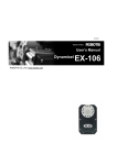
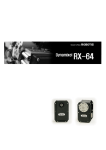
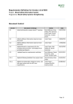
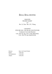
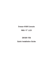
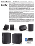
ROBOTIS e-Manual v1.05.01
EX-106+
Parts Photo
[EX-106+]
The Specification of EX-106+
•
•
•
Weight : 154g
Dimension : 40.1mm x 65.3mm x 50.1mm
Resolution : 0.06°
•
•
•
•
Gear Reduction Ratio : 184:1
Stall Torque : 107kgf.cm(at 18.5V 7A)
No load speed : 91rpm (at 18.5V)
Running Degree
0° ~ 251°
Endless Turn
•
•
•
•
•
•
•
•
•
•
Running Temperature : -5 ~ +80
Voltage : 12 ~ 18.5V (Recommended Voltage 14.8V)
Command Signal : Digital Packet
Protocol Type : RS485 Asynchronous Serial Communication (8bit,1stop, No Parity)
Link (Physical) : RS485 Multi Drop Bus
ID : 254 ID (0~253)
Communication Speed : 7343bps ~ 1 Mbps
Feedback : Position, Temperature, Load, Input Voltage, etc.
Material : Full Metal Gear, Aluminium Front Case, Engineering Plastic Body
Standby current : 55 mA
Control Table
Control Table consists of data regarding the current status and operation, which exists inside of Dynamixel. The user can control Dynamixel by changing data of Control Table via
Instruction Packet.
EEPROM and RAM
Data in RAM area is reset to the initial value whenever the power is turned on while data in EEPROM area is kept once the value is set even if the power is turned off.
Address
It represents the location of data. To read from or write data to Control Table, the user should assign the correct address in the Instruction Packet.
Access
Dynamixel has two kinds of data: Read-only data, which is mainly used for sensing, and Read-and-Write data, which is used for driving.
Initial Value
In case of data in the EEPROM Area, the initial values on the right side of the below Control Table are the factory default settings. In case of data in the RAM Area, the
initial values on the right side of the above Control Tables are the ones when the power is turned on.
Highest/Lowest Byte
In the Control table, some data share the same name, but they are attached with (L) or (H) at the end of each name to distinguish the address. This data requires 16bit, but it
is divided into 8bit each for the addresses (low) and (high). These two addresses should be written with one Instruction Packet at the same time.
Initial Value
Address
(Hexadecimal)
Name
0 (0X00)
1 (0X01)
Model Number(L)
Model Number(H)
2 (0X02)
Version of Firmware
R
3 (0X03)
4 (0X04)
5 (0X05)
ID
Baud Rate
Return Delay Time
O
6 (0X06)
CW Angle Limit(L)
7 (0X07)
CW Angle Limit(H)
8 (0X08)
CCW Angle Limit(L)
9 (0X09)
CCW Angle Limit(H)
10 (0X0A)
Drive Mode
the Highest Limit
Temperature
the Lowest Limit
Voltage
the Highest Limit
Voltage
Max Torque(L)
Area
E
E
P
M
11 (0X0B)
12 (0X0C)
13 (0X0D)
14 (0X0E)
Description
Access
R
R
(Hexadecimal)
107 (0X6B)
0 (0X00)
R
-
RW
RW
RW
1 (0X01)
34 (0X22)
0 (0X0)
RW
0 (0X00)
RW
0 (0X00)
RW
255 (0XFF)
RW
15 (0X0F)
RW
0(0X00)
Internal Limit Temperature
RW
80 (0X50)
Lowest Limit Voltage
RW
60 (0X3C)
Highest Limit Voltage
RW
240 (0XF0)
Lowest byte of Max. Torque
RW
255 (0XFF)
Lowest byte of model number
Highest byte of model number
Information on the version of
firmware
ID of Dynamixel
Baud Rate of Dynamixel
Return Delay Time
Lowest byte of clockwise Angle
Limit
Highest byte of clockwise Angle
Limit
Lowest byte of counterclockwise
Angle Limit
Highest byte of counterclockwise
Angle Limit
Dual Mode Setting
R
15 (0X0F)
16 (0X10)
17 (0X11)
18 (0X12)
24 (0X18)
25 (0X19)
A
26 (0X1A)
M
27 (0X1B)
28 (0X1C)
29 (0X1D)
30 (0X1E)
31 (0X1F)
32 (0X20)
33 (0X21)
34 (0X22)
35 (0X23)
36 (0X24)
37 (0X25)
38 (0X26)
39 (0X27)
40 (0X28)
41 (0X29)
42 (0X2A)
43 (0X2B)
Max Torque(H)
Status Return Level
Alarm LED
Alarm Shutdown
Torque Enable
LED
CW Compliance
Margin
CCW Compliance
Margin
CW Compliance Slope
CCW Compliance
Slope
Goal Position(L)
Goal Position(H)
Moving Speed(L)
Moving Speed(H)
Torque Limit(L)
Torque Limit(H)
Present Position(L)
Present Position(H)
Present Speed(L)
Present Speed(H)
Present Load(L)
Present Load(H)
Present Voltage
Present Temperature
Highest byte of Max. Torque
Status Return Level
LED for Alarm
Shutdown for Alarm
Torque On/Off
LED On/Off
RW
RW
RW
RW
RW
RW
3 (0X03)
2 (0X02)
36 (0X24)
36 (0X24)
0 (0X00)
0 (0X00)
CW Compliance margin
RW
1 (0X01)
CCW Compliance margin
RW
1 (0X01)
CW Compliance slope
RW
32 (0X20)
CCW Compliance slope
RW
32 (0X20)
Lowest byte of Goal Position
Highest byte of Goal Position
Lowest byte of Moving Speed
Highest byte of Moving Speed
Lowest byte of Torque Limit
Highest byte of Torque Limit
Lowest byte of Current Position
Highest byte of Current Position
Lowest byte of Current Speed
Highest byte of Current Speed
Lowest byte of Current Load
Highest byte of Current Load
Current Voltage
Current Temperature
RW
RW
RW
RW
RW
RW
R
R
R
R
R
R
R
R
ADD14
ADD15
-
44 (0X2C)
46 (0X2E)
47 (0X2F)
48 (0X30)
49 (0X31)
Registered
Moving
Lock
Punch(L)
Punch(H)
56(0X38)
Sensed Current(L)
57(0X39)
Sensed Current(H)
Address Function Help
EEPROM Area
Model Number
It represents the Model Number.
Firmware Version
It represents the firmware version.
ID
Means if Instruction is registered
Means if there is any movement
Locking EEPROM
Lowest byte of Punch
Highest byte of Punch
Lowest byte of Consuming
Current
Highest byte of Consuming
Current
R
R
RW
RW
RW
0 (0X00)
0 (0X00)
0 (0X00)
0 (0X0)
0 (0X00)
R
-
R
-
It is a unique number to identify Dynamixel.
The range from 0 to 253 (0xFD) can be used, and, especially, 254(0xFE) is used as the Broadcast ID.
If the Broadcast ID is used to transmit Instruction Packet, we can command to all Dynamixels.
Please be careful not to duplicate the ID of connected Dynamixel.
In slave mode, it is recommended the ID of slave motor be designated in the area other than ID areas(0~26).
Baud Rate
Address 0x04
It represents the communication speed. 0 to 254 (0xFE) can be used for it. This speed is calculated by using the below formula.
Speed(BPS) = 2000000/(Data+1)
Data
1
3
4
7
9
16
34
Set BPS
1000000.0
500000.0
400000.0
250000.0
200000.0
117647.1
57142.9
Target BPS
1000000.0
500000.0
400000.0
250000.0
200000.0
115200.0
57600.0
Tolerance
0.000 %
0.000 %
0.000 %
0.000 %
0.000 %
-2.124 %
0.794 %
103
207
19230.8
9615.4
19200.0
9600.0
-0.160 %
-0.160 %
Note : maximum Baud Rate error of 3% is within the tolerance of UART
communication.
Caution : The initial value of Baudrate is set to 1(1000000bps)
Drive Mode
Drive mode is set for Dynamixel.
Bit
Bit
7
Bit
6
Bit
5
Bit
4
Bit
Name
Contents
N/A
-
N/A
-
N/A
-
N/A
-
N/A
-
3
Bit
2
Bit
1
Bit
0
•
•
•
•
N/A
-
Master/Slave Mode
In case of 0: Master mode, In case of 1 : Slave mode
Normal/Reverse
Mode
In case of 0: Normal mode, In case of 1: Reverse
mode
Master Mode
In case of being used as dual joints, it is set to designate as master.
Slave Mode
In case of being used as dual joints, it is set to designate as slave.
General Mode
It is valid if it is master mode.
It is set if it uses the same rotation direction.
Reverse Mode
It is valid if it is master mode.
It is set if uses the rotation direction reversely.
Notes : Reverse mode is to change the actual rotation direction reversely. It can be used conveniently
when the robot with symmetrical joints layout is built.
Dual Joints
Dual joints are used as 1 joint by controlling 2 motors simultaneously.
To use the dual joints, 1 unit of motor set in master mode and 1 unit of motor set in slave mode are needed.
Next, the motors must be connected to each other using synchronization cable.
Notes : Slave is synchronized by directly receiving the control command through synchronization
cable from Master. Slave Mode unit responds to communication through command packets, but data
related to motor drive are processed only through the synchronization.
Return Delay Time
It is the delay time per data value that takes from the transmission of Instruction Packet until the return of Status Packet.
0 to 254 (0xFE) can be used, and the delay time per data value is 2 usec.
That is to say, if the data value is 10, 20 usec is delayed. The initial value is 250 (0xFA) (i.e., 0.5 msec).
CW/CCW Angle Limit
The angle limit allows the motion to be restrained.
The range and the unit of the value is the same as Goal Position(Address 30, 31).
•
•
CW Angle Limit: the minimum value of Goal Position(Address 30, 31)
CCW Angle Limit: the maximum value of Goal Position(Address 30, 31)
The following two modes can be set pursuant to the value of CW and CCW.
Operation Type
CW / CCW
Wheel Mode
the value of the both are 0
Joint Mode the value of the both are not 0
The wheel mode can be used to wheel-type operation robots since motors of the robots spin infinitely.
The joint mode can be used to multi-joints robot since the robots can be controlled with specific angles.
The Highest Limit Temperature
It is the highest limit of operating temperature.
The range for use is 10 to 99 (0x10~0x63). The unit is Celsius.
For example, if the value is 80, it is 80 .
If the internal temperature of Dynamixel exceeds this range, Over Heating Error Bit (Bit2) of Status Packet is returned as ‘1’ and
Alarm is triggered as set in the addresses 17 and 18.
Caution : Do not set The Highest Limit Temperature of Dynamixel above the initial value of
80 .
If Dynamixel is used at the temperature of 80
or higher, it may be damaged
The Lowest (Highest) Limit Voltage
It is the operation range of voltage.
50 to 250 (0x32 ~ 0x96) can be used. The unit is 0.1V.
For example, if the value is 80, it is 8V.
If Present Voltage (Address42) is out of the range, Voltage Range Error Bit (Bit0) of Status Packet is returned as ‘1’ and Alarm is triggered as set in the addresses
17 and 18.
Max Torque
It is the torque value of maximum output. 0 to 1023 (0x3FF) can be used, and the unit is about 0.1%.
For example, Data 1023 (0x3FF) means that Dynamixel will use 100% of the maximum torque it can produce while Data 512 (0x200)
means that Dynamixel will use 50% of the maximum torque. When the power is turned on, Torque Limit (Addresses 34 and 35) uses
the value as the initial value.
Status Return Level
It decides how to return Status Packet. There are three ways like the below table.
Value
0
1
2
Return of Status Packet
No return against all commands (Except PING Command)
Return only for the READ command
Return for all commands
When Instruction Packet is Broadcast ID, Status Packet is not returned regardless of Status Return Level.
Alarm LED
Alarm Shutdown
Dynamixel can protect itself by detecting errors occur during the operation.
The errors can be set are as the table below.
Bit
Bit
7
Bit
6
Name
Contents
0
-
Instruction Error
When undefined Instruction is transmitted or the Action command is delivered
without
the reg_write command
Bit
5
Bit
4
Bit
3
Overload Error
When the current load cannot be controlled with the set maximum torque
CheckSum Error
When the Checksum of the transmitted Instruction Packet is invalid
Range Error
When the command is given beyond the range of usage
When the internal temperature is out of the range of operating temperature set in
Bit
2
OverHeating Error
Bit
1
Angle Limit Error
Bit Input Voltage
0 Error
the Control Table
When Goal Position is written with the value that is not between CW Angle
Limit and CCW
Angle Limit
When the applied voltage is out of the range of operating voltage set in the
Control Table
It is possible to make duplicate set since the function of each bit is run by the logic of ‘OR’. That is, if 0X05 (binary 00000101) is set,
both Input Voltage Error and Overheating Error can be detected.
If errors occur, in case of Alarm LED, the LED blinks; in case of Alarm Shutdown, the motor output becomes 0 % by making the
value of Torque Limit(Address 34, 35) as 0.
RAM Area
Torque Enable
Value
0
1
Meaning
Keeps Torque from generating by interrupting the power
of motor.
Generates Torque by impressing the power to the motor.
LED
Value
0
1
Meaning
Turn OFF the LED.
Turn ON the LED.
Compliance
Compliance is to set the control flexibility of the motor.
The following diagram shows the relationship between output torque and position of the motor.
Compliance Margin
It exists in each direction of CW/CCW and means the error between goal position and present position.
The range of the value is 0~255, and the unit is the same as Goal Position.(Address 30,31)
The greater the value, the more difference occurs.
Compliance Slope
It exists in each direction of CW/CCW and sets the level of Torque near the goal position.
Compliance Slope is set in 7 steps, the higher the value, the more flexibility is obtained.
Data representative value is actually used value. That is, even if the value is set to 25, 16 is used internally as the representative value.
Step
1
2
3
4
5
6
7
Data Value
Data Representative Value
0 (0x00) ~ 3(0x03)
2 (0x02)
4(0x04) ~ 7(0x07)
4 (0x04)
8(0x08)~15(0x0F)
8 (0x08)
16(0x10)~31(0x1F)
16 (0x10)
32(0x20)~63(0x3F)
32 (0x20)
64(0x40)~127(0x7F)
64 (0x40)
128(0x80)~254(0xFE)
128 (0x80)
Punch
Currently this value is not used.
Goal Position
It is a position value of destination.
0~4095 (0xFFF) is available, and the unit is 0.06 degreee.
If Goal Position is out of the range, Angle Limit Error Bit (Bit1) of Status Packet is returned as ‘1’ and Alarm is triggered as
set in Alarm LED/Shutdown.
<The picture above is based on the front of relevant model.>
If it is set to Wheel Mode, this value is not used.
Moving Speed
It is a moving speed to Goal Position.
The range and the unit of the value may vary depending on the operation mode.
•
Join Mode
0~1023 (0X3FF) can be used, and the unit is about 0.111rpm.
If it is set to 0, it means the maximum rpm of the motor is used without controlling the speed.
If it is 1023, it is about 114rpm.
For example, if it is set to 300, it is about 33.3 rpm.
Notes: Please check the maximum rpm of relevant model in Joint Mode. Even if the motor is set to more
than maximum rpm, it cannot generate the torque more than the maximum rpm.
•
Wheel Mode
0~2047( 0X7FF) can be used, the unit is about 0.1%.
If a value in the range of 0~1023 is used, it is stopped by setting to 0 while rotating to CCW direction.
If a value in the range of 1024~2047 is used, it is stopped by setting to 1024 while rotating to CW direction.
That is, the 10th bit becomes the direction bit to control the direction.
In Wheel Mode, only the Torque control is possible, not speed.
For example, if it is set to 512, it means the torque is controlled by 50% of the maximum torque.
Torque Limit
It is the value of the maximum torque limit.
0 to 1023 (0x3FF) is available, and the unit is about 0.1%.
For example, if the value is 512, it is about 50%; that means only 50% of the maximum torque will be used.
If the power is turned on, the value of Max Torque (Address 14, 15) is used as the initial value.
Notes: If the function of Alarm Shutdown is triggered, the motor loses its torque because the value becomes
0. At this moment, if the value is changed to the value other than 0, the motor can be used again.
Present Position
It is the current position of Dynamixel.
The range and the unit of the value may vary depending on the operation mode.
•
Joint Mode
The range of the value is 0~4095 (0xFFF), and the unit is 0.06 degree.
•
<The picture above is based on the front of relevant model>
Wheel Mode
The range of the value is 0~65535(0XFFFF), and the unit is 0.06 degree.
In case of Wheel Mode, only the moving distance can be measured since the present location outputs the value of Encoder.
It is increased or decreased by 1 depending on the moving direction of wheel.
If it is decreased when the value is 0, it becomes 65535; if it is increased when it is 65535, the value becomes 0.
Total Moved Angle = (The value currently measured - The value measured in the past) x 0.06
According to the formula above, if the total moved angle is greater than 0, it is turned to the direction of CCW; if it is less than
0, it is turned to the direction of CW.
For example, The value is changed from 5000 to 10000, (10000 - 5000) x 0.06 = 300, and the total moved angle becomes 300
degrees.
Present Speed
It is the current moving speed.
0~2047 (0X7FF) can be used.
If a value is in the rage of 0~1023, it means that the motor rotates to the CCW direction.
If a value is in the rage of 1024~2047, it means that the motor rotates to the CW direction.
That is, the 10th bit becomes the direction bit to control the direction, and 0 and 1024 are equal.
The unit of this value varies depending on operation mode.
•
•
Joint Mode
The unit is about 0.111rpm.
For example, if it is set to 300, it means that the motor is moving to the CCW direction at a rate of about 33.3rpm.
Wheel Mode
The unit is about 0.1%.
For example, if it is set to 512, it means that the torque is controlled by 50% of the maximum torque to the CCW direction.
Present Load
It means currently applied load.
The range of the value is 0~2047, and the unit is about 0.1%.
If the value is 0~1023, it means the load works to the CCW direction.
If the value is 1024~2047, it means the load works to the CW direction.
That is, the 10th bit becomes the direction bit to control the direction, and 1024 is equal to 0.
For example, the value is 512, it means the load is detected in the direction of CCW about 50% of the maximum torque.
Notes: Current load is inferred from the internal torque value, not from Torque sensor etc.
For that reason, it cannot be used to measure weight or torque; however, it must be used only to detect
which direction the force works.
Present Voltage
It is the size of the current voltage supplied.
This value is 10 times larger than the actual voltage. For example, when 10V is supplied, the data value is 100 (0x64)
Present Temperature
It is the internal temperature of Dynamixel in Celsius.
Data value is identical to the actual temperature in Celsius. For example, if the data value is 85 (0x55), the current internal temperature
is 85 .
Registered Instruction
Value
0
1
Meaning
There are no commands transmitted by
REG_WRITE
There are commands transmitted by
REG_WRITE.
Notes: If ACTION command is executed, the value is changed into 0.
Moving
Value
0
1
Meaning
Goal position command execution is
completed.
Goal position command execution is in
progress.
Lock
Value
Meaning
0
EEPROM area can be modified.
1
EEPROM area cannot be modified.
Caution: If Lock is set to 1, the power must be turned off and then turned on again
to change into 0.
Sensed Current
It is the amount of current in use.
The range from 0 to 1023 is used, and the unit is 10mA.
The value less than 512 means the motor consumes the current and torques to the direction of CCW.
The value greater than 512 means the motor consumes the current and torques to the direction of CW.
512 is equal to 0mA, and it means there is no torque from the motor.
For example, if the value is 612, the motor torques to the direction of CW and consumes 1000mA(612-512=100 => 100x10mA =
1,000mA).
If the value is 312, the motor torques to the direction of CW and consumes 2000mA(512-312= -200 => 200x10mA=2,000mA).
Option Frame
The types of EX-106+ option frame are as follows.
FR05-F101_FR05-X101
FR05-S101
FR08-B101
FR08-H101
FR08-H110_FR08-D101
Horn
The types of EX-106+ Horn are as follows.
HN05-N101
HN05-T101
Combination
The following example shows the combination structure of option frames and horns.