1
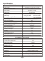
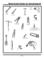
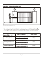
A10 Installation manual
INDUSTRIAL
SLIDING GATE
OPERATOR
Company Profile
Centurion Systems (Pty) Ltd, South Africa, has been manufacturing automatic gate systems since 1986,
and is committed to providing reliable, cost effective solutions in the field of gate and access
automation.
We offer a diverse range of products including gate motors, GSM-based products, garage door motors,
remote controls, keypads, traffic barriers, proximity access control and intercom systems.
Our products are developed by an in-house team of talented engineers that are constantly researching
new and innovative technologies to improve our existing products and expand our product range.
Our production facility in Johannesburg is ISO:9001 quality assurance certified, and all our products are
manufactured to the highest level of quality with a 100% test to specification.
Through a team of dedicated technicians and sales personnel, together with a fully fledged in-house
training facility, we are committed to providing unmatched service to our customers and support for our
products.
A worldwide network of distributors and installers ensure that our products remain The Automatic
Choice in access automation .
Further information is available on our website www.centsys.com.au
Centurion Systems (Pty) Ltd reserves the right to make changes to the products described in this document without notice and without
obligation of Centurion Systems (Pty) Ltd to notify any persons of any such revisions or changes. Additionally, Centurion Systems (Pty) Ltd
makes no representations or warranties with respect to this document.
No part of this document may be copied, stored in a retrieval system or transmitted in any form or by any means electronic, mechanical,
optical or photographic, without the express prior written consent of Centurion Systems (Pty) Ltd.
Page 2
Important Safety Instructions
ATTENTION
To ensure the safety of people, it is important that you read all the
following instructions. Incorrect installation or incorrect use of
the product could cause serious harm to people.
The installer, being either professional or DIY, is the last person on the site that can ensure that the
operator is safely installed, and that the whole system can be operated safely.
WARNINGS FOR THE INSTALLER
1.
CAREFULLY READ AND FOLLOW ALL INSTRUCTIONS
before beginning to install the product.
supplied with the product, or by Centurion Systems (Pty)
Ltd.
2.
This appliance is not intended for use by persons
(including children) with reduced physical, sensory or
mental capabilities, or lack of experience and knowledge,
unless they have been given supervision or instruction
concerning use of the appliance* by a person responsible
for their safety.
14. Make sure that the earthing system is correctly
constructed, and that all metal parts of the system are
suitably earthed.
15. Safety devices must be fitted to the installation to guard
against mechanical movement risks such as crushing,
dragging and shearing.
3.
All installation, repair, and service work to this product
must be done by a suitably qualified person.
16. It is recommended that at least one warning indicator light
be fitted to every system.
4.
Do not activate your gate opener unless you can see it and
can determine that its area of travel is clear of people, pets,
or other obstructions.
17. Always fit the warning signs visibly to the inside and
outside of the gate.
5.
NO ONE MAY CROSS THE PATH OF A MOVING GATE.
Always keep people and objects away from the gate and
its area of travel.
6.
NEVER LET CHILDREN OPERATE OR PLAY WITH THE
GATE CONTROLS, and do not allow children or pets near
the gate area.
7.
Secure all easily accessed gate opener controls in order to
prevent unauthorized use of the gate.
20. Do not leave packing materials (plastic, polystyrene, etc.)
within reach of children as such materials are potential
sources of danger.
8.
Do not in any way modify the components of the
automated system.
21. Dispose of all waste products like packaging materials,
worn out batteries, etc, according to local regulations.
9.
Do not install the equipment in an explosive atmosphere:
the presence of inflammable gas or fumes is a serious
danger to safety.
22. Always check the obstruction detection system, and
safety devices for correct operation.
10. Before attempting any work on the system, cut electrical
power and disconnect the batteries.
11. The mains power supply of the automated system must be
fitted with an all-pole switch with contact opening distance
of 3mm or greater. Use of a 5A thermal breaker with allpole circuit break is recommended.
12. Make sure that an earth leakage circuit breaker with a
threshold of 30mA is fitted upstream of the system.
13. Never short circuit the battery and do not try to recharge
the batteries with power supply units other than that
18. The installer must explain and demonstrate the manual
operation of the gate in case of an emergency, and must
hand the User/Warnings guide over to the user.
19. Explain these safety instructions to all persons authorized
to use this gate, and be sure that they understand the
hazards associated with automated gates.
23. Centurion Systems (Pty) Ltd does not accept any liability
caused by improper use of the product, or for use other
than that for which the automated system was intended.
24. This product was designed and built strictly for the use
indicated in this documentation. Any other use, not
expressly indicated here, could compromise the good
condition/operation of the product and/or be a source of
danger.
24. Everything not expressly specified in these instructions is
not permitted.
* Appliance should be product described in manual
WARNING
MOVING GATE CAN CAUSE
SERIOUS INJURY OR DEATH
KEEP CLEAR. GATE MAY MOVE AT
ANY TIME. DO NOT ALLOW
CHILDREN TO PLAY IN AREA OR
OPERATE GATE .
Page 3
Fast Track
These abbreviated instructions are for the experienced installer who needs a checklist to get a
standard installation up and running in the minimum of time.
Detailed installation features and functions are referred to later in this manual.
Mechanical Setup
Action
Step 1
Gather required tools and equipment
Page 13
Step 2
Heed necessary site considerations
Page 14-17
Step 3
Check cabling requirements
Page 18
Step 4
Secure foundation plate
Page 19-21
Step 5
Introduce oil
Page 22
Step 6
Mount gearbox
Page 23
Step 6 (chain)
Step 7
Mount chain drive hardware (Optional)
Mount rack
Step 7
6 (chain)
Page 26
Page 24
Mount chain (Optional)
Page 27
Step 8
Mount origin marker
Page 28
Step 9
Test endstops
Page 15
Page 4
Fast Track
Electrical Setup
Action
Step 1
Connect all wiring:
Page 30
Step 2
Get into programming mode:
Page 30
Fit the SET link.
Briefly depress the reset button.
Step 3
Set the gate limits:
Page 30
Press and hold TEST, release after one flash of L1.
Press and hold TEST, release after one or two
flashes of STATUS. (one flash = gate opens to the RIGHT.
two flashes = gate opens to the LEFT).
Step 4
Set additional features: (If required)
Step 5
Exit programming mode:
Page 32
Remove the SET link.
Step 6
Perform installation hand over
Page 5
Page 48
General Description
The A10 is a heavy duty sliding gate operator designed to open and close sliding gates.
In cases where chain, (as opposed to toothed rack) drive is required, an optional chain drive kit is
available.
The key to the A10's outstanding torque and duty cycle lies in the 3-phase induction motor and electronic
inverter that form the heart of the system. Single-phase 220-240VAC power is converted into variable
frequency 3-phase power, allowing electronically controlled soft starting and stopping of the motor.
An optional DC converter is available, containing back up batteries and UPS type backup circuits. This
enables the A10 to continue operating for a limited period in the event of a power failure.
In order to cater for high duty cycle installations, the A10 Endurance model is offered. This model utilizes a
continuously powered cooling fan, whilst the basic model utilizes the motor's standard shaft driven
cooling fan. The A10 heavyweight model is similar to the Endurance model with the exception of the 17
tooth output pinion. It is suitable for sites with a gate mass up to 2000kg
Gate travel limits are managed by an opto-electronic system, comprising a gate mounted origin marker
and an internal rotary encoder. This system yields precise and repeatable control over gate position.
Advanced features of the CP201 logic controller include:-
! Automated setup of gate endpoints (limits).
! Fail safe collision detection and auto reverse (adjustable sensitivity).
! Smoothed start/stop (ramp up/down).
! Multiple operational modes.
! Selectable, adjustable autoclosing.
! Pedestrian (partial) opening.
! Positive Close Mode.
! Safety input for sensitive edge/safety beam/inductive loop.
! Advanced lightning/surge protection.
! Timed courtesy light output.
! Multiple preflashing modes.
! SPRINT gate mode (high speed operation).
Lightning Protection
The A10 inverter and electronic controller utilizes the same proven surge protection philosophy that is
used in all CENTSYS products. While this does not guarantee that the unit will not be damaged in the
event of a lightning strike or power surge, it greatly reduces the likelihood of such damage occurring. The
earth return for the surge protection is provided via the mains power supply earth. In order to ensure that
the surge protection is effective, it is essential that the unit is properly earthed.
Page 6
Theft Protection
While care has been taken in the design of the A10 to prevent unauthorized removal (theft) of the unit, an
optional steel theft resistant cage is also available for added peace of mind.
70
384
Overall Dimensions
300
234
340 (Theft resistant cage)
All dimensions shown in millimetres
Figure 1 Overall Dimensions
Page 7
Specifications
A10 BASIC
SPECIFICATIONS
Power Supply
220-240V AC+/- 10%, 50Hz - 1 Phase
6A
Maximum Absorbed Current
Motor Voltage
220-240V AC 3 Phase
Output Pinion
20 Tooth Mod 4
Starting Thrust
(Standard speed)
40kgF
Rated Thrust
(Standard speed)
30kgF
Operating Speed @ Rated Thrust
(Sprint speed)
(Sprint speed)
30kgF
22.5kgF
1
16m/min
Adj. Up to 30m/min
Direct Drive Fan (1400RPM)
Motor Cooling
2
Duty Cycle (continuous)
45%
2
Duty Cycle (30 minute endurance)
65%
Ambient Temperature Range
O
-20 C to +50OC
Anti-crushing sensing
Electronic
Motor Thermal Protection
Electronic
20m
Maximum Gate length
IP Rating
44
Optional Battery Back-up
Yes
15.5kg
Shipping Mass of Unit
(Standard speed) 1000kg
Maximum Gate Mass
(Sprint speed)
600kg
DC CONVERTER SPECIFICATIONS
Input Voltage
12V DC
30A
Current Draw @ Rated Thrust
Rated Output Voltage
310V DC
3
Battery Charger
1A
20%
Maximum Duty Cycle
Thermal Protection
Electronic
Enclosure
IP65 External Plastic Enclosure
Dimensions
310mm X 240mm X 110mm
Battery Size
Std. 12V 7AH (External 40AH optional)
7 - 12 (7AH battery) 40 - 70 (40AH battery)
4
Open and Close Cycles
10kg (Inc 7AH Battery)
Shipping Mass
Page 8
A10 ENDURANCE
A10 HEAVY WEIGHT
220-240V AC +/- 10%, 50Hz - 1 Phase
220-240V AC +/- 10%, 50Hz - 1 Phase
6A
6A
220-240V AC 3 Phase
220-240V AC 3 Phase
20 Tooth Mod 4
17 Tooth Mod 4
(Standard speed)
40kgF
(Standard speed)
30kgF
30kgF
47kgF
22.5kgF
35kgF
(Sprint speed)
(Sprint speed)
1
16m/min
Adj. Up to 30m/min
13.6m/min
High Efficiency Fan (3000 RPM)
High Efficiency Fan (3000 RPM)
90%
90%
95%
95%
O
O
-20 C to +50 C
-20 C to +50OC
Electronic
Electronic
Electronic
Electronic
20m
17m
44
44
Yes
Yes
15.7kg
15.6kg
(Standard speed) 1000kg
(Sprint speed)
(1) Refer to RATED THRUST values
(2) At rated thrust and 25OC maximum ambient
temperature, unit in full shade.
O
600kg
2 000kg
(3) Upgradable on request.
(4) Dependent on site / environmental conditions.
Page 9
Duty Cycle Curves
Calculating the duty cycle
The duty cycle is the ratio of the actual operating time to the total time (opening plus
closing plus pause times). The formula for calculating it is the following:
To + Tc
x 100
To + Tc + Tp + Ti
opening time;
closing time;
pause time;
interval between a complete cycle and the next
Duty cycle % =
where: To
Tc
Tp
Ti
=
=
=
=
A10 BASIC Duty Cycle Curves
4m 500kg gate @ 20kg pull force. Air temperature=25°C. Unit in full shade.
Duty Cycle(%)
100
90
80
HS Open/ HS Cl os e
70
HS Open/ ST D Cl ose
ST D Open/ ST D Cl ose
60
50
40
20
30
40
50
60
70
Time (Minutes)
Figure 2 Duty Cycle Curves
Page 10
80
90
A10 ENDURANCE Duty Cycle Curve
All speed combinations
4m 500kg gate @ 20kg pull force. Air temperature=25°C. Unit in full shade.
Duty Cycle (%)
100
90
80
70
20
30
40
50
60
70
80
90
Time (Minutes)
Figure 3 Duty Cycle Curves
Examples of how to read the duty cycle curves:
Referring to Figure 2, an A10 Basic, opening and closing at standard (STD) speed (n
),
can run at a duty cycle of 65% for 30 minutes, a duty cycle of 50% for 45 minutes, and
a duty cycle of 45% for an unlimited time.
The same A10 Basic, opening at high speed (HS), and closing at standard (STD) speed
(6
), can run at a duty cycle of 78% for 30 minutes, a duty cycle of 65% for 45 minutes,
and a duty cycle of 60% for an unlimited time.
The same A10 Basic, opening AND closing at high speed (HS) (s
), can run at a duty
cycle of 90% for 30 minutes, a duty cycle of 83% for 45 minutes, and a duty cycle of
80% for an unlimited time.
Page 11
Product Identification
The actual components supplied may vary depending on the model purchased.
1
2
3
9
4
5
6
10
7
11
12
8
13
14
15
1.
2.
3.
4.
5.
6.
7.
8.
High Efficiency Fan*
Inverter Module
Inverter Fuse (F1 5A F/B)
Logic Controller Fuse (F2 50mA S/B)
Courtesy Light Fuse (F3 3A F/B)
Manual Release Handle
Lock Cover
Logic Controller
Figure 4 Product Identification
Page 12
9.
10.
11.
12.
13.
14.
15.
3 Phase Motor
Gate Mounted Origin Marker
Origin Sensor
Origin Marker Bracket
Encoder Sensor
Lower Cover
Foundation Plate
*Not fitted to BASIC model
Required Tools & Equipment
Electric
Drilling
Machine
Spanners
17mm
13mm
Screw Drivers:
3.5mm Flat
Hammer
G-Clamp x2
Crimping Tool
and Pin Lugs
Self locking
Pliers
Pliers
Pick
Masonry Bits - 6mm
20mm (For sites with rawlbolted
foundation plates)
Steel Bits 8,5mm/5,0mm/4,0mm
Hacksaw
Side Cutters
6mm Allen Key
4mm Allen Key
Spade
Level
Measuring Tape
Figure 5 Required Tools and Equipment
Page 13
Welding
Machine
Site Considerations
Install the gate operator only if:
1. It will not pose a hazard to the public.
2. There is sufficient clearance to a roadway and/or public thoroughfares.
3. The installation will meet all municipal and/or local authority requirements once
completed.
4. The gate mass, length and application is within the operator specifications.
5. The gate is in good working order, meaning:
! That it moves freely.
! Does not move on its own if left in any position.
6. It can be installed to have sufficient clearance between moving parts when
opening and closing to reduce the risk of personal injury and entrapment.
7. Pushbuttons or key switches, when required, can be positioned so that the gate
is in line of sight of the operator.
General considerations for the installation:
1. Always recommend the fitment of additional safety equipment such as safety
edges and safety beams, for additional protection against entrapment or other
mechanical risks.
2. Check that no pipes or electrical cables are in the way of the intended installation.
3. Check that enough space is available for the gate operator with the gate in the
required open position.
4. Check for loose sandy soil if installing foundations, as the soil condition may
require a larger foundation.
5. Never fit the operator on the outside of the gate, where the public has access to it.
Page 14
Endstops
1
1
H
h
Ø16mm
FIT ENDSTOPS (1) CAPABLE OF STOPPING THE GATE MOVING
AT RATED SPEED.
MAKE H³
hTO ENSURE GATE WILL NOT JUMP OVER ENDSTOP.
Figure 6 Gate Endstops
WARNING
Due to the high speed at which the A10 operator can move a gate, it is
extremely important to install endstops capable of stopping the gate
moving at the rated speed. Refer to Specifications as detailed on Page 8
for the operating speed.
Page 15
Anti-Lift Brackets
5
2
3
4
Figure 7 Anti-Lift Brackets
- Guide-rollers 2 must ensure that the gate is held vertically.
- Fit suitable anti-lift brackets 5 . The gap 3 should be <5mm to ensure
the gate cannot be lifted off the motor pinion.
- For improved safety fit additional support post 4 to prevent gate from
falling over if guide-rollers 2 fail.
Page 16
Starting & Running Forces
6
Figure 8 Starting and Running Forces
- The Centurion Systems (Pty) Ltd warranty will be void if the pull force 6 ,
and/or gate mass, exceeds the operator specification (see table below)
Model
Characteristic
Starting Force
Basic / Endurance
40kgF @ standard speed
Heavy Weight
47kgF
30kgF @ sprint speed
Running (rated) Force
30kgF @ standard speed
35kgF
22.5kgF @ sprint speed
Maximum gate mass
1000kg @ standard speed
600kg @ sprint speed
Page 17
2000kg
Cabling Requirements
3
4
Mains
isolator
switch
2
6
7
1
To dwelling
5
LEGEND
1.
220-240V AC mains cable via mains
isolator switch (3 core LNE 1,5mm2)†
2.
Intercom cable (n1 + 6 core) to
house.
5.
Infrared beams or safety edge (if
required) (3 core 0,5mm2
multistranded)
6.
Intercom cable (n2+2 core 0,5mm2
multistranded) to gate station.
7.
220-240V AC mains cable for lights
(3 core LNE 0,5mm2 provided load
does not exceed 400W)
2
3.
Radio receiver cable (3 core 0,5mm
multistranded).
4.
Pedestrian key switch (if required) (2
core 0,5mm2 multistranded).
n1 = number of cores required by intercom.
n2 = number of cores required by intercom.
† Screened cable is always recommended to provide better protection against lightning - earth one end of
screening.
Figure 9 Cabling Requirements
Page 18
Operator Installation
Foundation Plate Installation
Rack/Axle Clearance
Use steel rack
Remember to insert mtg bolts,
before fixing foundation plate.
28mm Minimum
Foundation plate
43-48mm
16mm Dia round
bar recommended
Figure 10 Rack Axle Clearance
Side Clearance
5mm
Lower cover is approximately 5mm wider than chassis each side. Allow additional 20mm each
side of lower cover if theft resistant bracket is to be fitted.
Figure 11 Side Clearance
Page 19
Operator Installation
Foundation Plate Installation - option 1
(Bolted down to existing concrete block)
! The LH concrete anchor 7
!
!
!
!
may need to be broken off in order to clear incoming
conduits.
Make sure the M10 bolts 8 which secure the gearbox are in place.
Refer to the Fig. 10 to ensure correct positioning. Mark through the foundation
plate holes to indicate where to drill holes for the M10 rawlbolts 9 .
Use extra washers 10 as required to ensure the foundation plate is level.
Drill the holes, grease the bolts, and bolt down the plate securely.
Use steel rack
Remember to
insert mtg bolts,
before fixing
foundation plate.
10
8
28mm Minimum
Foundation plate
43-48mm
8
16mm Dia round
bar recommended
7
9
96mm
200mm
see
above
178mm
250mm
400mm
Figure 12 Foundation Plate Installation - Existing Concrete Block
Page 20
Foundation Plate Installation - option 2
(Set in concrete)
13
13
200mm
11
12
11
12
250mm
400mm
Figure 13 Foundation Plate Anchors
! The anchors 11 must first be bent down as shown in Figure 13.
! Use self locking or crimping pliers to bend the anchor tips 12 to the horizontal
plane.
! Make sure the M10 bolts 13 which secure the gearbox are in place.
! Refer to Figure 14 to ensure correct positioning and set the foundation plate in
concrete to the level indicated
Allow 400mm slack cable to protrude from conduits
13
13
Set in concrete
to this level
20mm conduits
Figure 14 Set Foundation Plate in Concrete
Page 21
Important Information
Lubrication
The internal wormshaft/wormwheel gearset of the A10 is lubricated by means of
an oil bath.
In order to prevent possible leakage during shipping, the unit
is shipped with no oil inside the gearbox. A bottle containing 80 ml of EP 80W90 oil is included with the product, and
this MUST be introduced BEFORE operating the product.
ATTENTION
It is more convenient to insert the oil before bolting the unit down, as shown in Figure 15.
The A10 does not require routine oil changes. However in the event of the unit
losing oil due to stripping down or mechanical damage, the correct replacement
oil is EP 80W90 to API GL-5, i.e. Castrol EPX or equivalent.
If the gearbox is bolted down in the horizontal position during filling, the correct
level is reached when oil begins to spill from the filler hole.
1
2
3
Figure 15 Filling The Gearbox With Lubricant
Step 1: Remove dipstick from gearbox
Step 2: Cut the tip off the nozzle which will allow for the oil to pass through the
nozzle;unscrew the oil bottle cap; remove the seal from beneath the oil
bottle cap; replace the oil bottle cap onto the bottle and, attach the
extension tube to the nozzle
Step 3: Fill the gearbox with the oil provided
ATTENTION
PLEASE ensure that you ONLY USE THE FOLLOWING OIL
as qualified by CENTSYS:
Castrol SAF-XO 75w-90 Synthetic Final Drive Lubricant.
CENTSYS re-order code OIL80ML0X0/H.
Page 22
Operator Installation
Gearbox Mounting Down Details
A
Adjust jacking screws to give 4-6 mm chassis
foundation plate clearance.
(TIP: A 4mm allen key with a “Ball End” is
handy).
B
Check operator is level.
Jacking
Screw
4-6mm
M10 Nut
C
M10 Spring Washer
6mm Thick Load Spreader
Assemble nut, spring
washer, and load
spreader as shown.
Tighten nuts
progressively i.e. left
hand, then right
hand, then left hand.
D
Figure 16 Gearbox Mounting Down Details
Page 23
Double check that
jacking bolts are tight.
Joining/Mounting Rack
- A simple way of ensuring correct pitch spacing when joining steel rack is
to clamp a small off cut 14 between the two pieces.
- Check that weld 15 does not foul with meshing surfaces.
- Attach steel rack to gate using 25x25x5mm angle brackets 16 .
- For best results support rack every 300mm.
- Assuming the rail is level, the rack must also be mounted level with a 2 - 3mm
clearance 17 .
USEFUL TIP
l
Raise gearbox by an additional 3mm.
l
Put gearbox into manual mode (see page 41)
l
Mesh
rack and pinion fully and mount rack. Slide gate backwards and forwards
ensuring that rack mesh is smooth and never tight.
l
Drop gearbox by 3mm to create 3mm tooth clearance (Approximately 2.5 turns of the
jacking screws).
15
LEVEL
14
200 - 300mm
Figure 17 Joining Rack
Page 24
±300 mm
16
17
Figure 18 Mounting Rack
Page 25
Chain Drive Installation (Optional)
A
Remove all four captive
nuts from gearbox as
shown.
B
Assemble as
shown
Figure 19 Chain Drive Installation
Page 26
Installing Chain Drive Systems
5
IDLER
PULLEYS
4
>100mm
1
>100mm
2
3
Figure 20 Chain Drive Installation
- Weld rear anchor plate 1 onto gate such that centre line of tensioner
pin 2 is in line with top of the shaft on the idler pulley 4 . Allow at least
100mm between idler pulleys and anchor brackets.
- Align fixed anchor bracket 3 as for 1 .
- Ensure chain direction over sprocket is as shown (see 5 ).
Page 27
Origin Marker Mounting
MOUNTING CONFIGURATION
FOR STEEL RACK
SECURE USING
FASTENERS
PROVIDED
18
GATE
A
WELD
MOUNTING
BRACKET
PROVIDED TO
STEEL RACK
ED
CLOS
ORIGIN
MARKER
BRACKET
18
m
N 500m
R THA
TE
GREA
19
GATE CLOSED
GREATER THAN 500mm
18
B
18
C
13-20mm
19
Figure 21 Origin Marker Mounting
Page 28
- With the gate in the CLOSED position, mount the origin marker 18 a minimum
of 500mm from the origin sensor 19 . (See Fig. 21 isometric view A or plan
view B)
- Manually slide gate OPEN until origin marker 18 is in line with the origin sensor
19 . Ensure distance between face of marker 18 and front face of sensor 19
is between 13 and 20mm. (See Fig. 21, view C)
- Adjust distance by sliding the origin marker 18 along the slotted mounting
holes until the specified distance is achieved.
Page 29
Electrical Set-up
WARNING
1. Always check that the circuit breaker in the electrical panel is in the
OFF position, and that all high voltage circuits (more than 42.4V) are
completely isolated from the mains supply before doing any work.
2. Ensure that all low voltage systems (Less than 42.4V) are suitably
protected from damage, by disconnecting all sources of power such
as chargers and batteries before doing any work.
3. All electrical work must be carried out according to the requirements
of all applicable local electrical codes. (It is recommended that a
licensed electrical contractor perform such work.)
Connect all wiring
1. Ensure all interconnecting cables are securely in place (See diagrams on page
44 & 45).
2. Ensure single phase mains power is connected to the inverter (See diagram on
page 45).
Programming the gate limits
3. Disengage the manual release lever, move the gate to the middle of travel, and reengage the manual release lever.
4. Flip out the controller PCB as shown on page 31.
Get into programming mode
5.
Fit the SET link jumper to the SET pins shown in Figure 23.
6.
Press and release the RESET button. The STATUS light will flash five times. The
SET and L2 lights will now be on. Your are now in programming mode.
(See Fault Finder's Guide step 6)
NB: In case of the rack being underneath the pinion, first select inverted rack
option (See Menu Item 16 on page 50)
7.
Press and hold the TEST pushbutton (Figure 23) down, for one flash of L1, and
then release. L2 will go off, and L1 will now be flashing once per second.
8.
Determine right or left hand opening (as viewed from the release handle side of
the motor). Again press and hold the TEST button, but this time monitor the
STATUS light. Release the TEST button after ONE flash if gate opens to the
right, or TWO Flashes if gate opens to the left.
9.
The gate will begin to slowly open (If the gate starts to close, see Fault Finders
Guide, page 39, step 9).
Page 30
“Flip Out” Controller Mounting
Controller enclosure vertical
Controller enclosure raised
Controller enclosure propped
Figure 22 Controller Mounting
Page 31
10. The gate will slowly open until it hits
the open end stop, then slowly
close until it hits the closed end
stop.
RESET
Button
RESET
11. The gate will then open at normal
speed until the magnet passes the
origin, and then slowly open until it
hits the open end stop.
L1
Indicator LED
STATUS
STATUS
Indicator LED
L2
TEST
SET
12. The gate will then close at normal
speed until the magnet passes the
origin and then continue to close
slowly until it hits the closed end
stop.
L1
(See Fault Finder's Guide step 11)
CP201
L2
Indicator LED
TEST
Pushbutton
Fit SET
13. The gate will then open at normal
Link Here
speed until it reaches the minimum
pedestrian opening position. If a
wider pedestrian opening is Figure 23 Controller SET Link & Programming LED's
required, jog the gate further open
by shorting the PED input to COM.
When the correct position is reached, press the TEST button.
14. The STATUS light will flash five times, and L2 will light up. The gate limits have
now been set.
15. If no additional Features are required, then exit programming mode by
removing the SET link. Store the link by pushing it over ONE of the two pins.
16. Open and close the gate a few times to check operation.
Setting Additional Features (Optional)
The default factory settings on the CP201 Controller have been selected to suit most
applications. In many cases there would be no need to change the default settings.
A list of features can be found on page 47, with a detailed description of each feature
on page 35.
Determine What Features are Required
17. Determine from Table 2 on page 47 what Features are required together with
the STATUS or COUNT value.
Example: “To turn the AUTOCLOSE Feature ON”: According to Table 2 the
Autoclose feature is Feature number 2, and to turn it ON is a status of 1.
Page 32
Get Into Programming Mode (Exactly the same as for limits setup)
18. Fit the SET link jumper to the SET pins as shown in Figure 23.
19. Press and release the RESET button. The STATUS light will flash 5 times. The
SET and L2 lights will now be on. Your are now in programming mode.
(See Fault Finder's Guide step 19)
Selecting the Feature to Change
(This is the first of two steps in setting a Feature. This only SELECTS the feature to
change).
20. To select the Feature to change, Press and hold the TEST button while monitoring L1.
21. L1 will flash once then go off, twice in short succession then go off, three times
then go off, etc. Release the TEST button when the number of flashes is the
same as the Feature number to select.
Example 1:
To select a MODE OF OPERATION (In this case select CONDOMINIUM, that is
Feature number 4, to a status of 2 according to table 2 on page 49) Press and
hold the TEST button while monitoring L1:
The L1 light will flash once and pause,
then flash twice and pause….
then flash 3 times and pause….
then flash 4 times and pause….
At this moment release the TEST button to select Feature 4. L2 will turn off, and
L1 will keep on flashing 4 times and pausing to indicate that Feature 4 is
selected
NOTE: The STATUS of the Feature is not changed yet, the feature has
only been selected to be changed!
22. If an incorrect Feature is selected, press the reset button and restart from step 20.
None of the Feature settings will have been altered at this stage.
Changing the STATUS or COUNT value of a Feature.
23.To set the STATUS value of the Autoclose, Mode of Operation, Collision
Sensitivity, Positive Close Mode, Pre-flashing, Sprint Mode or Inverted Rack
Features:
Page 33
Press and hold the TEST button while monitoring the STATUS light. The
STATUS light will flash the same as for selecting a Feature. (See Step 21)
Release the TEST button when the number of flashes is the same as the STATUS
value required.
Example 1 (continued):
To set the MODE OF OPERATION to CONDOMINIUM:
After selecting the Feature, again press and hold the TEST button while
monitoring the STATUS light:
The STATUS light will flash once and pause,
then flash twice and pause…..
At this moment release the TEST button to give a STATUS value of 2. The
Mode of Operation has been changed to Condominium.
NOTE: Only after setting the STATUS, would the Mode of Operation
be changed to Condominium!
L2 will come back on, indicating that the STATUS has been updated.
24. To set the COUNT value of the Autoclose timer, Pedestrian Autoclose timer,
Courtesy light timer, Autoclose override timer, Pre-flashing time, Collision
counter, or the motor cutout timer Features:
Press and hold the TEST button while monitoring the STATUS light. After a
slight pause, the STATUS light will start flashing at an even rate. Count all the
flashes, and release the TEST button when the number of flashes is the same as
the COUNT value required.
Example 2:
Set the AUTOCLOSE TIME to 10 seconds (That is Feature number 3, to a
COUNT value of 10):
First select the Feature number 3 as in steps 20 to 21. Then press and
hold the TEST button while monitoring the STATUS light:
After a slight pause, the STATUS light will start flashing regularly:
Flash (1), Flash (2), Flash (3), Flash (4), Flash (5), Flash (6),
....Flash (9), Flash (10).
Page 34
Example 2 (continued):
At this moment release the TEST button to give a COUNT value of 10.
This sets the Autoclose timer to 10 seconds.
L2 will come back on, indicating that the COUNT has been updated.
Controller Features
The terminology "FEATURE 2-2" refers to Feature number 2 with a status of 2.
“FEATURE 3- COUNT” refers to Feature number 3, with a user specified COUNT
value.
Autoclose (FEATURE 2 - STATUS)
This can be programmed ON (FEATURE 2-1) or OFF (FEATURE 2-2). The factory
default is OFF. Autoclose has the function of automatically closing a gate after a
preset Autoclose time. Autoclose is automatically enabled in Condominium or
PIRAC mode.
A gate that is stopped while opening will always autoclose. A gate that is stopped
while closing will remain where it stopped indefinitely.
The autoclose time is set in FEATURE 3-COUNT. It can be set from 1 to 255 seconds.
It is possible for the user to temporarily turn off autoclose when the Mode of
Operation is either STANDARD and REVERSING. This is done by applying an
impulse to the TRG input at the time of opening the gate, for a period of time longer
than the AUTOCLOSE OVERRIDE TIME as set in FEATURE 8-COUNT. To provide
feedback that the override signal has operated, the gate will stop opening after the
override time. The instant the impulse is removed the gate will complete its opening
cycle. The Autoclose is now off and the gate will remain open indefinitely. The next
impulse received on TRG will initiate the closing cycle and the autoclose is automatically re-instated.
Modes of Operation (FEATURE 4 - STATUS)
It is possible to select 5 different Modes of Operation: STANDARD, CONDOMINIUM,
PIRAC, REVERSING AND PLC (FEATURE 4-1 to 4-5).Only one mode can be
activated at any one time. All the modes are triggered by the contact present
between the TRG input terminal and the COM terminal.
STANDARD MODE (FEATURE 4-1) (This is the factory default mode) - A
trigger impulse will cause the gate to start moving (either open or closed
depending on its position). A second impulse while the gate is still moving will
stop the gate. A third impulse will cause the gate to reverse its direction of
travel, i.e the action is START - STOP - REVERSE.
Page 35
CONDOMINIUM MODE (FEATURE 4-2) - Any trigger will cause a gate which
is closed or closing to open or re-open. If not already active the Autoclose will
automatically be turned on when Condominium Mode is selected. It is only
the Autoclose signal, which can close a gate in Condominium Mode. If a
trigger impulse is given while the gate is open the Autoclose time is reset to its
preset value.
PIRAC MODE (FEATURE 4-3) - An acronym for Passive Infra Red Autoclose,
this mode operates similarly to Condominium mode but instead of waiting for
the autoclose timer to close the gate, it will close as soon as an object that has
passed through the gate clears the infrared beam. If the beam is not broken
the gate will get to its fully open position and close after the preset Autoclose
time. This feature will only operate if infrared safety beams or if an inductive
loop is fitted (IRB terminal).
REVERSING MODE (FEATURE 4-4)- This mode is similar to standard mode
but instead of stopping a gate when it is in motion, a trigger will cause the gate
to reverse its direction of travel. It is thus impossible to leave a gate stationary
in a partly open position. The only two normally stable states are fully open or
fully closed. If the Autoclose is ON then the gate will always tend towards
being closed.
PLC MODE (FEATURE 4-5) - This mode provides separate open, close and
stop inputs, and is suitable for sites where a PLC (Programmable Logic
Controller) or PC is used to control access. Momentarily connecting FRX to
COM will open the gate, momentarily connecting PED to COM will close the
gate, and momentarily disconnecting LCK from COM will stop the gate.
Pedestrian Autoclose Time (FEATURE 5-COUNT)
A separate Autoclose timer exists for the pedestrian opening. The time can be set
from 1 to 255 seconds but cannot be turned off completely. The default time is 5
seconds.
Courtesy (Pillar) Light (FEATURE 6-COUNT)
The pillar light circuit has multiple functions:
! It operates as a courtesy light and switches on for a timed period (The
factory default is 2 minutes) (set by FEATURE 6-COUNT) every time the
gate triggers.
! It can be turned on for the preset timed period, by the application of a short
impulse between the SET terminal and COM.
! It can be turned ON permanently by application of an impulse longer than 3
seconds on SET and COM terminals. A short impulse thereafter will switch
Page 36
the lights off. The gate will not trigger open when using the SET trigger. The
fact that the pillar light is ON permanently is indicated by the STATUS LED
flashing once every 2 seconds.
! When the PED input is triggered the pillar light flashes for an adjustable (1 to
255 seconds) pre-flash time (FEATURE 11-COUNT) before the pedestrian
gate opens. (Default pre-flash time is 2 seconds).
! The contact can be used to operate a lamp, which will warn that the gate is
about to open. Selection of pre-flashing is done in FEATURE 10. Three
modes and OFF are selectable (The factory default is OFF):
#
Mode 1 - Light comes on only while gates are in motion.
#
Mode 2 - Light flashes at 1Hz for the pre-flash time and then flashes in
synchronism with the STATUS LED while the gates are in motion.
#
Mode 3 - Light comes on for the pre-flash time and while the gates are in
motion.
Collision Sensitivity (FEATURE 7-1 to 7-3) (THE FACTORY DEFAULT IS 7-1)
If the gate is obstructed the internal collision circuitry will activate. When the gate is
opening, and it is obstructed the gate will stop. During closing however, an obstruction will cause the gate to immediately stop and reverse direction. There is a counter
(FEATURE 12-COUNT) that monitors the number of collisions. If the collision count
is reached before the gate reaches the fully closed position all trigger signals are
inhibited for a 1-minute period. The STATUS LED flashing four times indicates this
condition. After the one-minute period, triggers will again become active, (with the
exception of Autoclose). The fault indication will continue to flash indefinitely after
the 1-minute period but will clear after the 1-minute period if a valid trigger is given.
The collision counter resets to zero after the 1 minute delay, or if the processor is
reset (e.g. By removing all power from the controller).
Positive Close Mode (FEATURE 9-STATUS)
Setting Positive Close Mode to ON (FEATURE 9-1) (default is OFF, FEATURE 9-2)
will allow the gate to drive up against the closed end stop without causing the
collision circuitry to operate. This Feature operates only during the ramping down
period in the closing direction.
Sprint Mode (FEATURE 13-STATUS, FEATURE 14-STATUS)
It is possible to select four different gate speeds. Feature 13 selects the opening
speed, while feature 14 selects the closing speed.
FEATURE13-1 Gate will open at standard speed.
Page 37
FEATURE13-2 Gate will open at standard speed + 30%.
FEATURE13-3 Gate will open at standard speed + 60%.
FEATURE13-4 Gate will open at standard speed + 90%.
FEATURE14- 1 Gate will close at standard speed.
FEATURE 14-2 Gate will close at standard speed + 30%.
FEATURE 14-3 Gate will close at standard speed + 60%.
FEATURE 14-4 Gate will close at standard speed + 90%.
CUTOUT TIMER: (FEATURE 15-COUNT)
The cutout timer will automatically shut off the motor after a predetermined time.
This is useful in the case where a mechanical failure prevents the gate from reaching
its end limit. The default cutout time is 60 seconds.
INVERTED RACK: (FEATURE 16-STATUS)
In the case where the rack is mounted UNDERNEATH the pinion (i.e.: upside down),
it is necessary to select the inverted rack option (FEATURE 16-1). This will ensure
that the gate directions are correctly calculated. The default status is OFF (FEATURE
16-2)
Page 38
Procedure to Programme Controller
Back to Factory Default Settings
1.
Apply power.
2.
Fit the "SET" link.
3.
Connect "PED" and "FRX" to "COM".
4.
Briefly depress the RESET button. STATUS light will flash five times, and then
L1 and L2 will illuminate.
5.
Remove the "SET" link and disconnect "PED" and "FRX" from "COM".
6.
Briefly depress the RESET button. STATUS light will flash five times.
7.
The card is now programmed to default settings as shown in Table 2 (see page
47) (Gate end points are not affected).
Fault Finder's Guide
All the known causes of problems are listed, according to the step number in the gate limits setup
instructions.
STEP
6. or
19
9
11
PROBLEM
POSSIBLE CAUSES & SOLUTIONS OF PROBLEM.
SET light is not on:
Check that the SET jumper is correctly fitted. Fit and
remove the SET jumper a few times to ensure good
contact.
L2 is not on:
Momentarily press the RESET button. The STATUS light will
flash 5 times, then L2 will illuminate.
STATUS light did not
flash five times:
Momentarily press the RESET button.
Gate starts to close
when it should be
opening.
Has gate direction been correctly determined? See step 8 in
the electrical setup.
Gate hits closed end
stop, but does not reopen
Has inverted rack option been selected (Menu item 16-1)? If in
doubt, reset controller to factory defaults (see above)
Is the magnetic sensor switch functioning correctly? Ensure
the gate magnet passes as close as possible to the sensor.
(see Fig 21 C) Page 28
Has inverted rack option been selected (Menu item 16)? If in
doubt, reset controller to factory defaults (see above)
Page 39
Receiver Installation
Figure 24 Receiver Installation
NOTE: Although a space is provided for locating a radio receiver within
the unit, best results will be achieved by mounting the receiver externally
as high as possible.
Page 40
Manual Release Operation
A
Manual release handle in closed position.
B
Open lock cover and insert key. Turn key ¼
turn counter clockwise to unlock.
C
Pull manual release handle down to enable
manual release
Page 41
Manual Release Latching
In the event of power failure, or product malfunction, it may be required to lock the
cover in place whilst "latching" the manual release (i.e. manual release permanently
enabled). This helps prevent theft of the unit, or its components, and provides full
protection from the elements.
Manual release latching is effected using a split pin as shown below.
B
A
Split pin shown positioned.
With the release handle lowered, insert the split
pin, (supplied with the mounting hardware kit),
through the hole in the gearbox as indicated.
D
C
Replace the cover and push the manual
release handle up to the closed position.
Turn key 1/4 turn clockwise to lock. Remove
key and close lock cover.
Page 42
CP201 Trigger Connections
(LED’s)
12V COM TRG IRB FRX COM LED PED LCK SET
LOOP DETECTOR
Figure 25 CP201 Trigger Connections
Page 43
PILLAR LIGHT PUSHBUTTON
HOLIDAY LOCKOUT KEYSWITCH
PEDESTRIAN KEYSWITCH
LOOP
STATUS LED
NO
NC
COM
+12V
IRB RECEIVER
NEG
IRB Tx
REMOTE CONTROL CIRCUITRY
12V or 24V
INFRA RED BEAM CIRCUITRY
NO
NC
+12V/24V
NEG
COM
RADIO RECEIVER
FREE EXIT CIRCUITRY
NO
NC
+12V/24V
NEG
COM
MAX CURRENT 250mA
PUSHBUTTON
FOR SWITCHING
PILLAR LIGHT (N/0)
HOLIDAY
LOCKOUT
SWITCH
(N/C)
PEDESTRIAN
KEYSWITCH (N/O)
(RETURN SPRING)
A10 Cable Routing
FRO
M
DC OPTIO
CON
VER NAL
TER
SIG
TO CNAL CA
ONT BLE
ROL
LER
TO P
IL
LIGH LAR
TS
FRO
M
MAI AC
NS
Figure 26 A10 Cable Routing
Page 44
A10 Cable Interconnections
CP200
R
INVERTE
SY
COURTE
PILLAR / NTIAL FREE)
E
T
O
LIGHT (P X 400W)
(MA
AC
220-240V SE
HA
P
E
L
G
SIN
L
N
E
AL FAN
OPTION
l
To optiona
ter
DC conver
R
ENCODE
SENSOR
ORIGIN
SENSOR
CP201
LLER
CONTRO
Figure 27 A10 Cable Interconnections
Page 45
LED Indicator Lights
The controller is fitted with diagnostic LED's (Light Emitting Diodes) that assist with the set-up and maintenance of the gate. Table 1 provides a description and purpose of the indicator LED's. See Figure 23 and 25 for
location.
NAME
COLOUR
ON
OFF
REMARKS
TRG
Red
Signal present
No signal
N/A
IRB
Green
Safeties clear
Safeties obstructed
N/A
FRX
Red
Signal present
No signal
N/A
PED
Red
Signal present
No signal
N/A
LCK
Green
System ready to
operate
System locked
N/A
SET
Red
Signal present
No signal
N/A
STATUS
Red
Gate fully open
Gate fully closed
1 Flash/sec - Pillar light on permanently
2 Flashes/sec - Thermal shutdown
3 Flashes/sec - Origin failure
4 Flashes/sec - Collision detector operated
5 Flashes/sec - Microprocessor reset
(During
normal
operation)
STATUS
Red
The number of flashes correspond to the
STATUS or COUNT value being set.
Red
Origin diagnostic
(Changes state to indicate origin status)
Off when gate is on "CLOSED" side.
On when gate is on "OPEN" side.
(During
programme
mode)
L1
(During
normal
operation)
L1
(During
programme
mode)
L2
Red
The number of flashes corresponds with
the FEATURE number being selected
If LED2 also on,
system reset to
factory default.
Red
DOSS diagnostic
(Changes state to indicate DOSS pulses)
(During
normal
operation)
L2
(During
programme
mode)
Red
System in programme
mode.
If L1 also on,
system reset to
factory default.
Table 1 LED Indicator Light Description & Purpose
Page 46
Controller Functions
FEATURE
DESCRIPTION
Gate Limit Settings
STATUS or COUNT
FEATURE
NUMBER
STATUS
VALUE
COUNT
VALUE
DESCRIPTION
1
-
-
See detailed instructions on page 30
1
-
ON
2
-
OFF (Default)
-
1 Flash = 1 second
15 seconds (Default)
1
-
STANDARD (Default)
2
-
CONDOMINIUM
3
-
PIRAC
4
-
REVERSING
5
-
PLC
Autoclose
2
Autoclose Time
3
Mode of Operation
4
Pedestrian Auto-close
5
-
1 Flash = 1 second
5 seconds (Default)
Courtesy Light
6
-
1 Flash = 10 seconds
120 seconds (Default)
1
-
HIGH (Default)
2
-
MEDIUM
Collision Sensitivity
7
Autoclose Override
8
Positive Close Mode
9
Preflashing
10
3
-
LOW
-
1 Flash = 1 second
3 seconds (Default)
1
-
ON
2
-
OFF (Default)
1
-
MODE 1
2
-
MODE 2
3
-
MODE 3
4
-
OFF (Default)
Preflash Time
11
-
1 Flash = 1 second
2 seconds (Default)
Collision Counter
12
-
1 Flash = 1 count
4 collisions (Default)
1
-
Standard speed (Default)
2
-
Standard speed + 30%
3
-
Standard speed + 60%
4
-
Standard speed + 90%
Opening sprint
mode select
13
Table 2 Controller Functions Menus and Submenus
Page 47
FEATURE
DESCRIPTION
Closing sprint
mode select
STATUS or COUNT
FEATURE
NUMBER
STATUS
VALUE
COUNT
VALUE
DESCRIPTION
14
Motor cutout time
15
Inverted Rack
16
1
-
Standard speed (Default)
2
-
Standard speed + 30%
3
-
Standard speed + 60%
4
-
Standard speed + 90%
-
1 Flash = 1 second
60 seconds (Default)
1
-
Rack below pinion
2
-
Rack above pinion (Default)
Table 2 continued Controller Functions Menus and Submenus
Installation Handover
Once the installation has been successfully completed and tested, it is important for the installer to explain the operation and safety requirements of the
system.
NEVER ASSUME THE USER KNOWS HOW TO SAFELY OPERATE AN AUTOMATED GATE. Even if
the user has used one before, it does not mean he knows how to SAFELY operate it. Make sure that the
user fully understands the following safety requirements before finally handing over the site.
Ensure that the user fully understands:
!
How to operate the manual release mechanism. (By demonstration).
!
How the obstruction detection and all other safety features work. (By demonstration).
!
All the safety considerations associated with operating an automated gate, and that he
understands that he is responsible for explaining these safety instructions to all other users of
the automated system:
1. Do not activate your gate opener unless you can see it and can determine that its area of
travel is clear of people pets, or other obstructions.
2. NO ONE MAY CROSS THE PATH OF A MOVING GATE. Always keep people and objects
away from the gate and its area of travel.
3. NEVER LET CHILDREN OPERATE OR PLAY WITH THE GATE CONTROLS, and do not
allow children or pets near the gate area.
4. Be careful with moving parts and avoid close proximity to areas where fingers or hands could
be pinched.
Page 48
5. Secure all easily accessed gate opener controls in order to prevent unauthorized use of the
gate.
6. Keep the automated gate system properly maintained, and ensure that all working areas
are free of debris and other effects that could compromise the gate operation and safety.
7. On a monthly basis, check the obstruction detection system, and safety devices for correct
operation.
8. All repair, and service work to this product must be done by a suitably qualified person.
9. This product was designed and built strictly for the use indicated in this documentation.
Any other use, not expressly indicated here, could compromise the service life/operation of
the product an/or be a source of danger.
10.Centurion Systems (Pty) Ltd does not accept any liability caused by improper use of the
product, or for use other than that for which the automated system was intended.
11.Ensure that the customer is in possession of the User Guide and also complete the
installation details in the back of the User Guide.
Installation Details
Installation Date:
Installer's Name:
Installer's Address:
Installation Checked By:
Installer's Telephone Number:
Page 49
Notes
Page 50
Notes
Page 51
0.07.B.0032 A10
Installation Manual-10Jul2012
www.centsys.com.au