Download Compaq Armada 1130 System information

Transcript
. . . . . . . . . . . . . . . . . . . . . . . . .
Reference Guide
Compaq Armada 1100 Family of Personal Computers
Reference Guide
Compaq Armada 1100 Family of Personal Computers
• Controls and Indicators
• Maximizing Battery Life
• Computer Upgrades
• Diagnostics
• Troubleshooting
262446-002
COVER.PM5
1
9/25/97, 12:59 PM
. . . . . . . . . . . . . . . . . . . . . . . . .
Notice
The information in this guide is subject to change without notice.
COMPAQ COMPUTER CORPORATION SHALL NOT BE LIABLE
FOR TECHNICAL OR EDITORIAL ERRORS OR OMISSIONS
CONTAINED HEREIN; NOR FOR INCIDENTAL OR
CONSEQUENTIAL DAMAGES RESULTING FROM THE
FURNISHING, PERFORMANCE, OR USE OF THIS MATERIAL.
This guide contains information protected by copyright. No part of this
guide may be photocopied or reproduced in any form without prior written
consent from Compaq Computer Corporation.
 1996 Compaq Computer Corporation.
All rights reserved. Printed in the U.S.A.
Compaq, LTE, Contura, Registered U. S. Patent and Trademark Office.
Armada is a trademark of Compaq Computer Corporation.
Contura Registered in the Philippines Patent Office
Microsoft and MS-DOS are registered trademarks of Microsoft Corporation.
Windows is a trademark of Microsoft Corporation.
The software described in this guide is furnished under a license
agreement or nondisclosure agreement. The software may be used or
copied only in accordance with the terms of the agreement.
Product names mentioned herein may be trademarks and/or registered
trademarks of their respective companies.
Reference Guide
Compaq Armada 1100 Family of Personal Computers
Second Edition (November 1996)
First Edition (June 1996)
Part Number 262446-002
Compaq Computer Corporation
Part Number: 262446-002 Writer: Lorise Fazio Saved by: Johnnie Abercrombie
Saved Date: 08/26/96 1:57 PM 12:32 PM File Name: NOTI-US.DOC
Part Number: 262446-002 Writer: Lorise Fazio Saved by: Johnnie Abercrombie
Saved Date: 08/26/96 1:57 PM 12:32 PM File Name: NOTI-US.DOC
. . . . . . . . . . . . . . . . . . . . . . . . .
Federal Communications
Commission Notice
This equipment has been tested and found to comply with the
limits for a Class B digital device, pursuant to Part 15 of the FCC
Rules. These limits are designed to provide reasonable protection
against harmful interference in a residential installation. This
equipment generates, uses, and can radiate radio frequency energy
and, if not installed and used in accordance with the instructions,
may cause harmful interference to radio communications.
However, there is no guarantee that interference will not occur in a
particular installation. If this equipment does cause harmful
interference to radio or television reception, which can be
determined by turning the equipment off and on, the user is
encouraged to try to correct the interference by one or more of the
following measures:
■ Reorient or relocate the receiving antenna.
■ Increase the separation between the equipment and the receiver.
■ Connect the equipment into an outlet on a circuit different from
that to which the receiver is connected.
■ Consult the dealer or an experienced radio or television
technician for help.
Modifications
The FCC requires the user to be notified that any changes or
modifications made to this device that are not expressly approved by
Compaq Computer Corporation may void the user's authority to
operate the equipment.
Cables
Connections to this device must be made with shielded cables with
metallic RFI/EMI connector hoods to maintain compliance with
FCC Rules and Regulations.
Airline Travel Notice
Use of electronic equipment aboard commercial aircraft is at the
discretion of the airline.
v
Part Number: 262446-001 - Writer: Dianne Fielden - Saved by: JohnnieA
Saved Date: 02/29/96 8:33 AM, 12:16 PM - File Name: AGENCY.DOC
. . . . . . . . . . . . . . . . . . . . . . . . .
European Notice
Products with the CE Marking comply with both the EMC Directive
(89/336/EEC) and the Low Voltage Directive (73/23/EEC) issued by
the Commission of the European Community.
Compliance with these directives implies conformity to the
following European Norms:
■ EN55022 (CISPR 22)-Radio Frequency Interference
■ EN50082-1 (IEC801-2, IEC801-3, IEC801-4)-Electromagnetic
Immunity
■ EN60950 (IEC950)-Product Safety
Canadian Notice
This Class B digital apparatus meets all requirements of the
Canadian Interference-Causing Equipment Regulations.
Avis Canadien
Cet appareil numérique de la classe B respecte toutes les exigences
du Règlement sur le matériel brouilleur du Canada.
Japanese Notice
vi
Part Number: 262446-001 - Writer: Dianne Fielden - Saved by: JohnnieA
Saved Date: 02/29/96 8:33 AM, 12:16 PM - File Name: AGENCY.DOC
. . . . . . . . . . . . . . . . . . . . . . . . .
Battery Notice
!
WARNING: This computer contains an internal lithium battery-powered
real-time clock circuit. There is a risk of explosion and injury if the
battery is incorrectly replaced or handled improperly. Do not attempt to
recharge, disassemble, immerse in water, or dispose of it in fire.
Replacement should be done by a Compaq authorized service provider
using the Compaq spare part for this computer.
!
WARNING: The computer contains a nickel metal hydride battery pack.
There is a risk of fire and chemical burn if the battery pack is handled
improperly. Do not disassemble, crush, puncture, short external contacts,
dispose of in water or fire, or expose it to temperatures higher than 60
degrees C.
In North America, dispose of nickel metal hydride batteries by
taking advantage of the Compaq battery recycling program. You
will be provided with a postage-paid battery pack mailer
preaddressed to a reclamation facility where the metals are recycled.
In Europe, do not dispose of batteries with general
household waste. Dispose of or recycle them by
using the public collection system or returning them
to Compaq, your authorized Compaq Partners, or
their agents.
Energy Star Compliance
As an Energy Star Partner, Compaq Computer Corporation has
determined that this product meets the Energy Star guidelines for
energy efficiency. The Energy Star Computers Program was created
by the EPA to promote energy efficiency and reduce air pollution
through more energy-efficient equipment in homes, offices, and
factories. Compaq products achieve this by reducing the power
consumption when not being used. Using the power-saving features
will reduce energy use and maximize battery life.
Agency
Part Number: 262446-001 - Writer: Dianne Fielden - Saved by: JohnnieA
Saved date: 02/29/96 8:33 AM - File Name: AGENCY.DOC
vii
. . . . . . . . . . . . . . . . . . . . . . . . .
Contents
Preface
Using This Guide ........................................................................................ xv
Chapter 1
Finding Information About Your Computer
Printed and Online References ...................................................1-1
Ordering Backup Diskettes ........................................................1-2
Worldwide Telephone Numbers.................................................1-3
Chapter 2
Taking a Look at the Computer
Front and Side Components .......................................................2-2
Keyboard Components...............................................................2-3
Status Panel Indicators ...............................................................2-4
Integrated Trackball ...................................................................2-5
Rear Components.......................................................................2-6
Bottom Components ..................................................................2-7
Chapter 3
Using the Keyboard
Keyboard Components...............................................................3-2
Using the Hotkeys......................................................................3-3
Customizing the Popup Window .........................................3-5
Using the Special Function Keys ...............................................3-6
Using the Numeric Keypad ........................................................3-7
Chapter 4
Managing Power
Power Button .............................................................................4-2
Standby (also called Suspend) .............................................4-3
Hibernation..........................................................................4-4
When to Turn Off the Computer..........................................4-5
Contents
ix
Part Number: 262446-001 Writer: Dianne Fielden Saved by: Johnnie Abercrombie
File name: TOC.DOC Saved date: 09/25/97 2:32 PM 2:44 PM
. . . . . . . . . . . . . . . . . . . . . . . . .
Using AC Power ........................................................................4-6
To connect an AC Adapter ..................................................4-6
Using Battery Power ..................................................................4-7
Reading the Battery Gauge ..................................................4-7
Resolving a Low-Battery Condition ....................................4-8
Extending Battery Pack Operating Time .............................4-9
Removing the Battery Pack ............................................... 4-10
Inserting the Battery Pack.................................................. 4-12
Charging the Battery Pack ................................................. 4-13
Power Properties ...................................................................... 4-14
Turning Hibernation Off or On.......................................... 4-15
Battery Conservation Levels.............................................. 4-16
Chapter 5
Using Security
Setting Passwords Properties .....................................................5-2
Power-On Password ...................................................................5-2
Establishing a Power-On Password ....................................5-2
Entering the Power-On Password ........................................5-3
Deleting/Changing the Power-On Password........................5-3
If You Forget Your Power-On Password.............................5-3
Establishing a Setup Password ...................................................5-4
Deleting/Changing a Setup Password ..................................5-4
Identifying Quick Controls.........................................................5-5
Initiating Quick Controls .....................................................5-5
Using a Cable Lock....................................................................5-7
x
Contents
Writer: Dianne Fielden - Saved by: Johnnie Abercrombie - Saved date: 09/25/97 2:32 PM
Part Number: 262446-001 - File name: TOC.DOC
. . . . . . . . . . . . . . . . . . . . . . . . .
Chapter 6
Upgrading the Computer
Installing Software .....................................................................6-2
Adding Memory.........................................................................6-3
Chapter 7
Connecting External Equipment
Device Manager Utility..............................................................7-1
Add New Hardware Icon............................................................7-2
Connecting a Printer...................................................................7-2
Connecting an AC Adapter ........................................................7-3
Connecting an Auto Adapter......................................................7-4
Connecting an External Enhanced Keyboard .............................7-5
Connecting an External Monitor ................................................7-6
Connecting a Mouse or External Trackball ................................7-7
Chapter 8
Working with PCMCIA Devices
Types of PC Cards .....................................................................8-2
Inserting a PC Card ....................................................................8-4
Removing a PC Card..................................................................8-6
Chapter 9
Caring for the Computer
Routine Care ..............................................................................9-2
Travel Guidelines .......................................................................9-3
Shipping Guidelines ...................................................................9-4
Contents
xi
Writer: Dianne Fielden - Saved by: Johnnie Abercrombie - Saved date: 09/25/97 2:32 PM
Part Number: 262446-001 - File name: TOC.DOC
. . . . . . . . . . . . . . . . . . . . . . . . .
Chapter 10
Diagnostics
Accessing Diagnostics ..........................................10-1
Accessing Diagnostics from Windows .............................. 10-1
Running Computer Checkup (TEST) ....................................... 10-2
Running the View System Information(Inspect Utility)........... 10-4
Chapter 11
Troubleshooting
Checklist .................................................................................. 11-1
Interpreting Messages on the Screen ........................................ 11-2
Solving Minor Problems .......................................................... 11-2
Solving Battery Problems .................................................. 11-3
Solving Diskette/Diskette Drive Problems ........................ 11-6
Solving Hard Drive Problems............................................ 11-7
Solving Hardware Installation Problems ........................... 11-8
Solving Keyboard and Embedded Numeric
Keypad Problems............................................................... 11-9
Solving Memory Problems .............................................. 11-10
Running the Monitor Self-Test ........................................ 11-10
Solving PC Card (PCMCIA Card) Problems................... 11-11
Solving Power Problems ................................................. 11-13
Solving Printer Problems................................................. 11-14
Solving Display Screen Problems.................................... 11-15
Solving Software Application Problems.......................... 11-17
Solving Sound Problems ................................................. 11-17
Solving Trackball/Mouse Problems................................. 11-18
Cleaning the Trackball..................................................... 11-20
Cleaning the Trackball Assembly.................................... 11-21
Servicing the Computer.......................................................... 11-23
Preparing for a Call to Customer Support .............................. 11-23
xii
Contents
Writer: Dianne Fielden - Saved by: Johnnie Abercrombie - Saved date: 09/25/97 2:32 PM
Part Number: 262446-001 - File name: TOC.DOC
. . . . . . . . . . . . . . . . . . . . . . . . .
Appendix A
Specifications ......................................................................................... A-1
Appendix B
POST Error Messages ..............................................................................B-1
Appendix C
Connector Pin Assignments....................................................................C-1
Appendix D
Power Cord Set Requirements
General Requirements ............................................................... D-1
Country-Specific Requirements ................................................ D-2
Appendix E
Regulatory Agency Identification Numbers ...........................................E-1
Index.......................................................................................................... I-1
Contents
xiii
Writer: Dianne Fielden - Saved by: Johnnie Abercrombie - Saved date: 09/25/97 2:32 PM
Part Number: 262446-001 - File name: TOC.DOC
. . . . . . . . . . . . . . . . . . . . . . . . .
Preface
Using This Guide
Purpose
This guide is a supplemental reference that takes you further than
Quick Setup with general information about the computer,
troubleshooting and diagnostics, and technical specifications.
Symbols and Conventions
The following format conventions distinguish elements of the text
throughout this guide:
■
Key names appear in a boldfaced type looking very much the
way they appear on the keyboard. For example, Home, End,
Backspace, Tab.
■
When keys must be pressed at the same time, the action is
represented by the key names and the plus (+) symbol. For
example, Ctrl+Alt+Delete keys.
■
The names of files are presented in uppercase italic type
as shown here: FILENAME. The names of commands or
directories are presented in uppercase type as shown here:
COMMAND or DIRECTORY. Commands that are to be entered
at the system prompt are shown on a separate line.
■
When you need to type something without pressing the Enter
key, you are directed to "type" the information.
■
When you need to type information and press the Enter key, you
are directed to "enter" the information.
xv
Part Number: 262446-001 Writer: Dianne Fielden Saved by: JohnnieA
Saved Date: 02/29/96 9:33 AM 12:32 PM File Name: PREFACE.DOC
. . . . . . . . . . . . . . . . . . . . . . . . .
The following words and symbols mark special messages
throughout this guide:
!
WARNING: Text set off in this manner indicates that failure to
follow directions could result in bodily harm or loss of life.
CAUTION: Text set off in this manner indicates that failure to
follow directions in the caution could result in damage to
equipment or loss of information.
IMPORTANT: Text set off in this manner presents clarifying
information or specific instructions.
NOTE: Text set off in this manner presents commentary, sidelights,
or interesting points of information.
xvi
Preface
Part Number: 262446-001 Writer: Dianne Fielden Saved by: JohnnieA
Saved Date: 02/29/96 9:33 AM 12:32 PM File Name: PREFACE.DOC
. . . . . . . . . . . . . . . . . . . . . . . . .
Chapter 1
Finding Information
About Your Computer
In this chapter you will learn about the references that come with
your computer and where to find them.
References are provided for you in two ways:
■
As printed materials
■
As online information accessible from the computer screen
NOTE: The printed and online references that come with the
computer vary by model.
Printed and Online References
The following printed references come with your computer:
■
Quick Setup
■
Reference Guide
■
Introducing Microsoft Windows 95
■
Safety & Comfort Guide
■
Warranty and service information
■
Customer registration material
The following online references are preinstalled on your computer:
■
Compaq Reference Guide
■
Microsoft Windows 95
■
Safety & Comfort Guide
■
Compaq Dictionary
The online references installed on the computer include the user's
guides, application help, software utilities help, and customer
support information. Many are accessible from the Compaq
Information Center folder, an icon on the desktop screen, which is
also available from the Start menu. Others can be accessed from the
application or utility screens.
Finding Information About Your Computer
Part Number: 262446-002 - Writer: Lorise Fazio - Saved by: Johnnie Abercrombie
Saved date: 08/26/96 3:19 PM- File Name: CH1.DOC
1-1
. . . . . . . . . . . . . . . . . . . . . . . . .
CAUTION: Most online references are available only through the
Windows interface. If you delete Windows, those references will
also be deleted. Therefore, Compaq recommends that you not
delete Windows software.
Ordering Backup Diskettes
Compaq recommends that you create a backup of the software
preinstalled on the computer. Or, for an additional cost, you can
order backup diskettes from Compaq for all software preinstalled on
this computer.
To order backup diskettes, refer to the "Worldwide Telephone
Numbers" listed in this chapter. If an order form is included with
your computer, complete the form and return it. Or call one of the
numbers listed on the order form.
IMPORTANT: Before calling Compaq to place your order, find the
serial number on the bottom of your computer. This number is
necessary for all backup diskette purchases.
1-2
Finding Information About Your Computer
Part Number; 262446-002 - Writer: Lorise Fazio - Saved by; Johnnie Abercrombie
Saved date: 08/26/96 3:19 PM - File Name: CH1.DOC
. . . . . . . . . . . . . . . . . . . . . . . . .
Worldwide Telephone Numbers
Locate your geographical area from the following table and use one
of the telephone numbers for Compaq assistance.
General Information Numbers—Product information, technical
assistance, and the location of your nearest Compaq authorized
dealer, reseller, or service provider.
Technical Support Numbers—Hardware technical support in
analyzing system configuration and diagnostic problems or
troubleshooting.
Customer Support Numbers—Information on service and support
programs including warranty, product catalogs, and white papers.
PaqFax Numbers—Automatic facsimile response system for
technical and product specific information that is transmitted to any
fax machine. PaqFax is available 24 hours a day.
NOTE: Telephone numbers are subject to change without notice.
Worldwide Telephone Numbers
Country
Code
Telephone Number
General Information
+54
-1-796-1616
Technical Support
+54
-1-796-1717
Location
Argentina
Australia
General Information
61-2-9911-1999
Technical Support
61-2-9911-1955
PaqFax
61-2-9911-1982
Austria
General Information
0222/8 78-16 16
Technical Support
0222/8 78-16-16
Ordering Backup Software
+31
-55-38-43-39
Continued
Finding Information About Your Computer
Part Number: 262446-002 - Writer: Lorise Fazio - Saved by: Johnnie Abercrombie
Saved date: 08/26/96 3:19 PM - File Name: CH1.DOC
1-3
. . . . . . . . . . . . . . . . . . . . . . . . .
Worldwide Telephone Numbers Continued
Country
Code
Telephone Number
General Information
+32
-2-716-95-11
Compaq Care Center
+32
-2-716-96-96
Compaq Care Center Fax
+32
-2-716-95-85
General Fax
+32
-2-725-22-13
FaxPaq
+32
-2-716-96-99
QuickLine
+32
-2-716-95-92
Ordering Backup Software
+32
-2-716-96-78
Ordering Backup Software Fax
+32
-2-716-96-79
Location
Belgium
Brazil
General Information
55-11-246-7866
Canada
General Information
1-905-707-1715
Technical Support
1-800-OKCOMPAQ
(1-800-652-6672)
Customer Support
1-800-263-5868
Ordering Backup Software
1-800-952-7689
Battery Pack Recycling
1-800-263-5868
Caribbean
General Information
011-713-514-4220
Technical Support
011-713-518-2200
Chile
General Information
56-2-274-1911
Technical Support
56-2-274-3007
China
General Information
861-68313399
Technical Support
861-68346721
Colombia
General Information
57-1-312-0201
Technical Support
57-1-345-0266
Continued
1-4
Finding Information About Your Computer
Part Number; 262446-002 - Writer: Lorise Fazio - Saved by; Johnnie Abercrombie
Saved date: 08/26/96 3:19 PM - File Name: CH1.DOC
. . . . . . . . . . . . . . . . . . . . . . . . .
Worldwide Telephone Numbers Continued
Country
Code
Telephone Number
General Information
+42
-2-232-8772
Technical Support
+42
-2-232-8772
General Information
+45
-45-90-45-90
Technical Support
+45
-45-90-45-45
+358
-0-615-599
Location
Czech Republic
Denmark
Finland
General Information
Technical Support
9800-206-720
+358
-0-6155 9870
General Information
+33
-1-41-33-41-33
Technical Support
+33
-1-41-33-44-55
QuickLine (BBS)
France
Germany
(0,12 DM/2 sec. or 3,60 DM/min.)
Menu Selection
0190/88 80 80
Notebook Hotline
0190/88 80 82
(0,48 DM/min.)
QuickLine
0180/5 21 21 18
FaxPaq
0180/5 21 21 19
Hong Kong
General Information
852-28681382
Technical Support
852-90116633
PaqFax
852-28671648
Hungary
General Information
+36
-1-201-8776
Technical Support
+36
-1-201-8776
Continued
Finding Information About Your Computer
Part Number: 262446-002 - Writer: Lorise Fazio - Saved by: Johnnie Abercrombie
Saved date: 08/26/96 3:19 PM - File Name: CH1.DOC
1-5
. . . . . . . . . . . . . . . . . . . . . . . . .
Worldwide Telephone Numbers Continued
Location
Country
Code
India
General Information
PaqFax
BBS
Italy
General Information
Technical Support
Customer Support
Telephone Number
91-80-559-6023
91-80-559-8989
91-80-559-8900
+39
+39
+39
Japan
General Information
Technical Support
Windows 95 Support
Ordering Backup Software
FaxStation
Korea
General Information
Technical Support
-2-57-59-03-61
-2-57-59-03-00
-1-67-82-50-12
0120-101-589
0120-101-589
0120-505-589
0120-250-589
81-3-5402-0991
82-2-3470-07001
82-2-523-3575
82-082-902-77774
Malaysia
General Information
603-717-1188
Technical Support
603-718-1636
Mexico
General Information
525-229-7900
Technical Support
525-229-7910
PaqFax
525-229-7920
Netherlands
General Information
0182-565805
Customer Support
06-91681616
(Dfl. 0.75/min)
Fax
06-8991116
(Dfl. 0.40/min)
QuickLine Bulletin Board
0182-572366
Continued
1-6
Finding Information About Your Computer
Part Number; 262446-002 - Writer: Lorise Fazio - Saved by; Johnnie Abercrombie
Saved date: 08/26/96 3:19 PM - File Name: CH1.DOC
. . . . . . . . . . . . . . . . . . . . . . . . .
Worldwide Telephone Numbers Continued
Location
Country
Code
Telephone Number
New Zealand
General Information
64-9-307-3969
Norway
General Information
+47
-22-07-20-00
Technical Support
+47
-22-07-20-20
General Information
+48
-2-630-3535
Technical Support
+48
-2-630-3535
General Information
+351
-1-4120132
Technical Support
+351
-1-4120132
Poland
Portugal
Singapore
General Information
65-753-6688
Customer Support Center
65-750-3030
PaqFax
65-750-4514
South Africa
General Information
27-11-728-6999
Technical Support
27-11-728-6999
Spain
General Information
+34
-1-640-1500
Technical Support
+34
-1-640-1302
General Information
+46
-8-703-5240
Technical Support
+46
-8-703-5240
PaqFax (hämtfax)
+46
-8-703-5225
QuickLine (BBS)
+46
-8-703-5220
Sweden
Continued
Finding Information About Your Computer
Part Number: 262446-002 - Writer: Lorise Fazio - Saved by: Johnnie Abercrombie
Saved date: 08/26/96 3:19 PM - File Name: CH1.DOC
1-7
. . . . . . . . . . . . . . . . . . . . . . . . .
Worldwide Telephone Numbers Continued
Location
Country
Code
Telephone Number
Switzerland
Technical Support
157/64-00
QuickLine Bulletin Board
01/8 38-24 21
Ordering Backup Software
155/62-06
PaqFax
01/8 38-22 38
Taiwan
General Information
886-2-7351000
Technical Support
886-2-3761170
BBS
886-2-3761175
Thailand
General Information
62-2-679-6222
United Arab Emirates (Dubai)
General Information
+97
14 -818100
United Kingdom
General Information
0990-134456
FaxPaq
0181-332-3550
QuickLine Bulletin Board
0181-332-9499
United States
General Information
1-713-514-6864
Technical Support
1-800-OKCOMPAQ
(1-800-652-6672)
Customer Support
1-800-345-1518
PaqFax
1-800-345-1518, Option 1
Download Facility
(modem access only)
1-713-518-1418
Ordering Backup Software
1-800-952-7689
Battery Pack Recycling
1-800-524-9859
Venezuela
General Information
1-8
58-2-953-6944
Finding Information About Your Computer
Part Number; 262446-002 - Writer: Lorise Fazio - Saved by; Johnnie Abercrombie
Saved date: 08/26/96 3:19 PM - File Name: CH1.DOC
. . . . . . . . . . . . . . . . . . . . . . . . .
Chapter 2
Taking a Look
at the Computer
Your notebook computer is equipped with many components,
including levers, buttons, indicators, and connectors. This chapter
familiarizes you with the components on the computer and how to
use them.
External devices such as a printer, serial device, monitor, keyboard,
and mouse can be connected to your computer to enhance its
functionality. The icons located on the rear of the computer help
you identify these connectors. See Chapter 7, "Connecting External
Equipment," for more details.
Illustrations and tables on the following pages identify the
computer's primary components, including:
■
Front and side components
■
Keyboard components
■
Status panel indicators
■
Integrated trackball
■
Rear components
■
Bottom components
Taking a Look at the Computer
Part Number: 262446-001 Writer: Dianne Fielden Saved by: Johnnie Abercrombie
Saved Date: 08/26/96 2:30 PM 12:22 PM File Name: CH2.DOC
2-1
. . . . . . . . . . . . . . . . . . . . . . . . .
Front and Side Components
1
5
7
2
3
4
6
Front and Side Components
Front and Side of the Computer
Ref.
Component
Function
n
Handle bracket (2)
Allows the handle to be attached
NOTE: To attach the handle, move
the tilt feet aside and rotate the
concealed handle brackets toward the
rear of the computer
o
p
q
Keyboard tilt feet (2)
Tilt the keyboard 4 degrees
Diskette drive
Internal drive for 3.5-inch diskettes
PC Card slots
Accept one Type III, or two Type II, or
two Type I PC Cards
r
s
Display latches (2)
Open the computer
PC Card release levers
Release PC Cards
NOTE: Before releasing a card, click the
PC Card indicator on the taskbar. Click
Stop for the card you want to remove.
When the system prompts you to remove
the card, swing the top or bottom release
lever to the left until the card ejects.
t
2-2
Battery compartment button
Opens battery compartment
Taking a Look at the Computer
Part Number: 262446-001 Writer: Dianne Fielden Saved by: Johnnie Abercrombie
Saved Date: 08/26/96 2:30 PM 12:22 PM File Name: CH2.DOC
. . . . . . . . . . . . . . . . . . . . . . . . .
Keyboard Components
1
2
3
4
5
7
6
7
Keyboard
Keyboard Components
Ref Component
Function
n
Power button
o
p
r
s
Status panel
Function keys
F1–F12
Embedded numeric
keypad
Cursor keys
Integrated trackball
t
Palm Rest (2)
When pressed the first time, turns on the computer.
When pressed once after the computer is on, initiates
Standby (Suspend). When pressed the second time,
exits Standby. See Chapter 4, “Managing Power,” for
details.
NOTE: To turn off the computer, use Windows Shut
Down from the Start menu. In case of a severe
system lock-up, when the mouse doesn't work and
Ctrl+Alt+Del is not recognized by the unit, use
Ctrl+Alt + the power button to shut down the unit.
Displays computer status indicators.
Used for a specific functions in applications and
operating systems.
Allows two operating modes, numeric (if Fn+NumLk
key is on) and edit (if Fn+NumLk key is off).
Allows cursor to move up, down, right, left.
Moves the pointer around the screen; functions as a
mouse.
Designed to rest the part of your palms closest to the
wrist when you pause at the keyboard. Do not use the
palm rest while you are typing.
q
Taking a Look at the Computer
Part Number: 262446-001 Writer: Dianne Fielden Saved by: Johnnie Abercrombie
Saved Date: 08/26/96 2:30 PM 12:22 PM File Name: CH2.DOC
2-3
. . . . . . . . . . . . . . . . . . . . . . . . .
Status Panel Indicators
4
2
3
1
8
6
5
7
Status Panel Indicators
2-4
Ref.
Indicator
Function
n
Power/
standby
Turns on when power to the computer is turned on.
Blinks when computer is in Standby (Suspend). Turns off
when computer is in Hibernation or powered off.
o
Battery
charge
Turns on when computer is turned on and when battery
is fast charging. Blinks for low-battery condition. Turns
off when battery pack is fully charged.
p
q
Hard drive
Turns on when hard drive is being accessed.
Diskette
drive
Turns on when diskette drive is being accessed.
r
Battery
gauge
Shows voltage remaining in battery pack when running
on battery power. Indicators do not represent equal
quantities of time. Only one indicator is on at a time.
Computer is in a low-battery condition when the
indicator next to the - (minus) icon comes on.
s
t
u
Caps Lock
Turns on when Caps Lock function is on.
Scroll Lock
Turns on when the Scroll key is pressed.
Num Lock
Turns on when the NumLk function is on.
Taking a Look at the Computer
Part Number: 262446-001 Writer: Dianne Fielden Saved by: Johnnie Abercrombie
Saved Date: 08/26/96 2:30 PM 12:22 PM File Name: CH2.DOC
. . . . . . . . . . . . . . . . . . . . . . . . .
Integrated Trackball
4
1
2
3
Integrated Trackball
The integrated trackball eliminates the need to carry a mouse when
traveling.
The trackball n is designed to be used with either hand for cursor
movement and button selection. The top button o functions as a left
mouse button, and the bottom button p functions as a right mouse
button. The ball q controls the pointer when rolled with your thumb.
Button functions and other trackball features can be customized
using the mouse utility located on the Control Panel. To access the
mouse utility, click Start, click Settings, click Control Panel, then
double-click the Mouse/Trackball icon. Refer to the online Compaq
Reference Guide for more information.
NOTE: For information about cleaning the trackball, refer to
Chapter 11, "Troubleshooting."
Taking a Look at the Computer
Part Number: 262446-001 Writer: Dianne Fielden Saved by: Johnnie Abercrombie
Saved Date: 08/26/96 2:30 PM 12:22 PM File Name: CH2.DOC
2-5
. . . . . . . . . . . . . . . . . . . . . . . . .
Rear Components
2
3
1
5
4
Rear Components
Components on the Rear of Computer
2-6
Ref.
Component
Function
n
o
Power connector
Connects the AC Adapter cable.
Parallel connector
Connects optional parallel devices,
such as a printer.
p
Serial connector
Connects optional serial devices, such
as a mouse or CD-ROM drive.
q
Keyboard/mouse connector
Connects an external keyboard, mouse,
or other pointing device.
r
External monitor
connector
Connects an external monitor.
Taking a Look at the Computer
Part Number: 262446-001 Writer: Dianne Fielden Saved by: Johnnie Abercrombie
Saved Date: 08/26/96 2:30 PM 12:22 PM File Name: CH2.DOC
. . . . . . . . . . . . . . . . . . . . . . . . .
Bottom Components
2
1
Bottom Components
Bottom Components
Ref
Component
Function
n
o
Battery compartment
Contains the battery pack.
Memory compartment
Contains the optional memory
expansion board.
Taking a Look at the Computer
Part Number: 262446-001 Writer: Dianne Fielden Saved by: Johnnie Abercrombie
Saved Date: 08/26/96 2:30 PM 12:22 PM File Name: CH2.DOC
2-7
. . . . . . . . . . . . . . . . . . . . . . . . .
Chapter 2
Taking a Look at the Computer
Part Number 262446-001 File Name CH2.DOC
Writer Dianne Fielden 08/26/96 2:30 PM 12:22 PM
2-8
. . . . . . . . . . . . . . . . . . . . . . . . .
Chapter 3
Using the Keyboard
Keyboard features on the computer are designed to enhance its
functionality. This chapter familiarizes you with the parts of the
keyboard and how to use the following features:
■
Keyboard components
■
Hotkeys
■
Special function keys
■
Embedded numeric keypad
Using the Keyboard
Part Number: 262446-001 Writer: Dianne Fielden Saved by: JohnnieA
Saved Date: 02/27/96 1:08 PM 12:24 PM File Name: CH3.DOC
3-1
. . . . . . . . . . . . . . . . . . . . . . . . .
Keyboard Components
1
2
3
4
5
7
6
7
Keyboard
Keyboard Components
Ref Component
Function
n Power button
When pressed the first time, turns on the computer.
When pressed once after the computer is on, initiates
Standby (Suspend). When pressed the second time,
exits Standby. See Chapter 4, “Managing Power,” for
details.
NOTE: To turn off the computer, use Windows Shut
Down from the Start menu. In case of a severe system
lock-up, when the mouse doesn't work and
Ctrl+Alt+Del is not recognized by the unit, use
Ctrl+Alt + the power button to shut down the unit.
Displays computer status indicators.
Used for a specific function in applications and
operating systems.
Allows two operating modes, numeric (if Fn+NumLk
key is on) and edit (if Fn+NumLk key is off).
Allows cursor to move up, down, right, left.
Moves the pointer around the screen; functions as a
mouse.
Designed to rest the part of your palms closest to the
wrist when you pause at the keyboard. Do not use the
palm rest while you are typing.
o Status panel
p Function keys
F1–12
q Embedded
numeric keypad
r Cursor keys
s Integrated
trackball
t Palm Rest (2)
3-2
Using the Keyboard
Part Number: 262446-001 Writer: Dianne Fielden Saved by: JohnnieA
Saved Date: 02/27/96 1:08 PM 12:24 PM File Name: CH3.DOC
. . . . . . . . . . . . . . . . . . . . . . . . .
Using the Hotkeys
The hotkey combinations (Fn+F4 through F9) simplify special
computer operations. These hotkeys cannot be accessed from an
external keyboard.
Hotkeys
Hotkey Assignments and Functions
Feature
Hotkeys
Function
Switching to the
External Monitor
Fn+F4
System Beeps
Fn+F5
Toggles three ways between computer
display, external monitor display, or both
displays simultaneously.
Turns on or off the system beeps, such as
for Standby, low battery, and POST.
Continued
Using the Keyboard
Part Number: 262446-001 Writer: Dianne Fielden Saved by: JohnnieA
Saved Date: 02/27/96 1:08 PM 12:24 PM File Name: CH3.DOC
3-3
. . . . . . . . . . . . . . . . . . . . . . . . .
Hotkey Functions and Assignments Continued
Feature
Quick Lock/
QuickBlank
Hotkeys
Fn+F6
Battery Conservation
Level
Fn+F7
Contrast Control
Fn+F8
Function
Initiates QuickLock, which disables the
keyboard and mouse, and QuickBlank,
which clears the screen. Enter power-on
password to reactivate keyboard, mouse,
and screen.
Displays the battery conservation
setting in a pop-up window. Use the left
and right arrow keys to select a different
setting.
NOTE: See Chapter 4, "Managing
Power," for more information.
Adjusts the display contrast. Press right
arrow key to increase contrast; press left
arrow key to decrease contrast.
NOTE: On models with color TFT
displays, contrast control is not
applicable.
Brightness Control
Fn+F9
Adjusts the brightness. Press right
arrow key to increase light intensity;
press left arrow key to decrease light
intensity.
Extended Text
Fn+T
Duplicates blank lines so text fills the
screen; the size of the displayed
characters doesn't change.
NOTE: Extended text is supported only
in text mode and only on the computer
display, not on an external monitor.
3-4
Using the Keyboard
Part Number: 262446-001 Writer: Dianne Fielden Saved by: JohnnieA
Saved Date: 02/27/96 1:08 PM 12:24 PM File Name: CH3.DOC
. . . . . . . . . . . . . . . . . . . . . . . . .
Customizing the Popup Window
Windows allows you to set the size and location of the popup window.
To access this feature, double-click the Hotkey Popup icon in the
Control Panel.
1. Click the option that sets the size/location of the popup window.
2. Make the desired changes.
3. Click OK to save your changes.
IMPORTANT: This popup window can be accessed only from within the
applications that support the video popup mode. If a popup does not
display correctly, exit the application and press the Hotkeys again to
invoke the popup window.
Using the Keyboard
Part Number: 262446-001 Writer: Dianne Fielden Saved by: JohnnieA
Saved Date: 02/27/96 1:08 PM 12:24 PM File Name: CH3.DOC
3-5
. . . . . . . . . . . . . . . . . . . . . . . . .
Using the Special Function Keys
Some keys on the keyboard provide special functions, depending on
the application you are using. These keys are described in the
following table:
Special Function Keys
Key
Function
Alt
Application dependent, used in combination with another
key for a specific function. Check the application software
documentation you are using.
Backspace
Moves the cursor left and deletes characters as it moves to the
left.
Caps Lock
When the CapsLock indicator is on, capitalizes all letters typed.
Ctrl
Application dependent; used in combination with other keys for
specific functions. Check the documentation for the application
software you are using.
Esc
Often assigned a specific task by the application. Frequently used
as an exit key.
F1–F12
Used for a specific function in applications and operating systems.
Check the application software documentation you are using.
NumLk
Activate this function by pressing Fn+End/NumLk. When the
NumLk indicator lights up, the embedded numeric keypad is
activated. NOTE: To change keyclick volume, activate the numeric
keypad. Then press Ctrl+Alt and the plus key (colon, semi-colon
key) repeatedly to increase keyclick volume. Press Ctrl+Alt and
the minus key (the letter "P") repeatedly to decrease keyclick
volume. (Keyclick volume can be heard only in MS-DOS sessions.)
Pause
Temporarily suspends screen scrolling. Activate this function by
pressing Fn+Pause.
PrtSc
Prints the information on the screen line-by-line to a local printer.
Using this key will print only the information on the screen.
Activate this function by pressing Fn+PrtSc.
Scroll
When the Scroll Lock indicator is on, prevents the screen from
scrolling. Access this function by pressing Fn+Scroll.
Ctrl+Alt+Delete
Restarts the system after the computer has been turned on.
Ctrl+Alt + power
button
Turns off the computer if the system locks up.
NOTE: Shut Down on the Windows Start menu is the
recommended way to turn off the computer.
Initiates Hibernation.
Fn + power button
3-6
Using the Keyboard
Part Number: 262446-001 Writer: Dianne Fielden Saved by: JohnnieA
Saved Date: 02/27/96 1:08 PM 12:24 PM File Name: CH3.DOC
. . . . . . . . . . . . . . . . . . . . . . . . .
Using the Numeric Keypad
The embedded numeric keypad is a section of the keyboard that
converts to a numeric keypad when the NumLk function is activated by
pressing Fn+NumLk. Use this toggle key function to enable and
disable the embedded numeric keypad.
Embedded Numeric Keypad
Using the Keyboard
Part Number: 262446-001 Writer: Dianne Fielden Saved by: JohnnieA
Saved Date: 02/27/96 1:08 PM 12:24 PM File Name: CH3.DOC
3-7
. . . . . . . . . . . . . . . . . . . . . . . . .
Chapter 3
Using the Keyboard
Part Number 262446-001 File Name CH3.DOC
Writer Dianne Fielden Saved Date 02/27/96 1:08 PM 12:24 PM
3-8
. . . . . . . . . . . . . . . . . . . . . . . . .
Chapter 4
Managing Power
Your computer is equipped with power features that allow you to
manage power usage, extend battery operating time, and conserve
battery power. Most power settings are controlled in Power
Properties, located in the Control Panel.
This chapter describes the following power management functions:
■
Power button
■
AC power
■
Low-battery condition
■
Battery power
■
Power properties
Managing Power
Part Number: 262446-001 Writer: JohnnieA Saved by: Johnnie Abercrombie
Saved Date: 09/17/96 12:26 PM File Name: CH4.DOC
4-1
. . . . . . . . . . . . . . . . . . . . . . . . .
Power Button
The power button performs the following functions:
■ Turns on the computer—Press the power button once when the
computer is off, in Standby (also called Suspend), or in Hibernation.
When you turn on the computer, the power/standby indicator on the
status panel lights up.
Power Button and Power/Standby Indicator Light
■
■
■
4-2
Initiates Standby (Suspend)—Press the power button once when
the computer is on.
NOTE: Suspend can also be accessed from the Start menu.
Initiates Hibernation—Press Fn + power button.
Exits Standby or Hibernation—Press the power button after the
computer has entered Standby or Hibernation.
Managing Power
Part Number: 262446-001 Writer: JohnnieA Saved by: Johnnie Abercrombie
Saved Date: 09/17/96 12:26 PM File Name: CH4.DOC
. . . . . . . . . . . . . . . . . . . . . . . . .
Standby (also called Suspend)
When you finish working, or if you want to pause in the middle of
your applications, press the power button once to initiate Standby.
This feature puts the computer to sleep (for up to 168 hours with a
fully charged battery pack), uses very little power, and saves your
place in your applications.
During Standby, most of the major components (hard drive,
processor, and display) shut down after a period of inactivity. Press
the power button once and the computer returns your work to the
screen exactly where you left off.
How Standby is initiated
■
Automatically when a pre-defined timeout has been reached.
(You can set the Standby timeout period in Power Properties.)
■
Manually at any time by pressing the power button.
■
Manually at any time by clicking Suspend from the Start menu.
When Standby is initiated
■
The computer beeps (once if system initiated; twice if user
initiated).
■
The screen goes blank.
■
The power/standby indicator blinks.
When exiting Standby
■
Press the power button once.
■
The computer beeps once.
■
The power/standby indicator turns on.
■
The "instant-on" feature lets you pick up your work right where
you left off. No information is lost.
IMPORTANT: The computer will not exit Standby (Suspend) if the
battery is low or dead. In this case, install a fully charged battery pack
or plug in an external power source. When a new power source is
connected to the computer, press the power button to exit Standby and
display your information on screen. (See "Resolving a Low-Battery
Condition" in this chapter.)
Managing Power
Part Number: 262446-001 Writer: JohnnieA Saved by: Johnnie Abercrombie
Saved Date: 09/17/96 12:26 PM File Name: CH4.DOC
4-3
. . . . . . . . . . . . . . . . . . . . . . . . .
Hibernation
Hibernation is a safeguard condition during which all the
information in system memory is saved to the hard drive and power
to the computer is turned off. When you resume work, your
information is returned to the screen exactly where you left off. No
information is lost.
Hibernation has the following benefits:
■
Since the computer is turned off and there is no drain on the
battery pack, your computer can remain in Hibernation for an
unlimited time.
■
You can manually save your place in any application or when
making a presentation
■
Information is automatically saved when the computer reaches a
low-battery condition (as long as Hibernation has not been
turned off).
How Hibernation is initiated
To save your place in your applications and turn power off
completely to your computer, press Fn + the power button to initiate
Hibernation.
System-initiated Hibernation occurs when the computer reaches a
critical low-battery condition. To protect against loss of
information, the computer automatically saves all information in
system memory to the hard drive and then turns off. Press the power
button once to resume work.
When exiting Hibernation
To resume work after Hibernation is initiated, do the following:
1. While the computer is still in Hibernation, install a fully charged
battery pack or connect to an external power source.
2. Turn on the computer by pressing the power button.
The computer exits Hibernation. The information that was saved
to the hard drive returns to the screen at the point where
Hibernation was initiated.
NOTE: To stop the restoration of information, press
Fn+Ctrl+Break.
4-4
Managing Power
Part Number: 262446-001 Writer: JohnnieA Saved by: Johnnie Abercrombie
Saved Date: 09/17/96 12:26 PM File Name: CH4.DOC
. . . . . . . . . . . . . . . . . . . . . . . . .
When to Turn Off the Computer
If you plan to store the computer for an extended period, turn off the
computer and remove the battery pack. This reduces the battery
pack's discharge rate and extends its life.
If you use the computer frequently, and you want "instant-on"
convenience, you do not have to turn off the computer. Simply
initiate Standby (Suspend) when you're not using it.
NOTE: The battery continues to drain while the computer is in
Standby. If you want to charge a battery pack while you are not
using the computer, connect the computer to external power and
turn it off. The battery pack charges whether the computer is on
or off.
To turn off the computer when in Windows applications, click
Shut Down from the Start menu. When the power/standby indicator
light goes off, the computer has been successfully shut down.
NOTE: In case of a severe system lock-up, when the mouse doesn't
work and Ctrl+Alt+Del is not recognized by the unit, use Ctrl+Alt + the
power button to shut down the unit. This method can also be used if
you are working in DOS mode (an option chosen from the Shut Down
menu). In this instance, Shut Down is not available because Windows
isn't running.
Managing Power
Part Number: 262446-001 Writer: JohnnieA Saved by: Johnnie Abercrombie
Saved Date: 09/17/96 12:26 PM File Name: CH4.DOC
4-5
. . . . . . . . . . . . . . . . . . . . . . . . .
Using AC Power
They way you connect the AC Adapter to the computer depends on
the type of adapter that came with your computer.
To connect the AC Adapter
Follow these steps to connect the AC Adapter:
1. Connect the power cord to the AC Adapter n.
2. Plug the AC Adapter cable o into the computer.
3. Plug the power cord p into an electrical outlet.
4. Turn on the computer.
1
2
3
Connecting an AC Adapter with Power Cord to the Computer
4-6
Managing Power
Part Number: 262446-001 Writer: JohnnieA Saved by: Johnnie Abercrombie
Saved Date: 09/17/96 12:26 PM File Name: CH4.DOC
. . . . . . . . . . . . . . . . . . . . . . . . .
Using Battery Power
Reading the Battery Gauge
The battery gauge, located on the status panel, has five indicator lights
that represent the amount of power remaining in the battery pack.
The indicators do not represent equal amounts of time. Instead, one
indicator at a time turns on to indicate how much battery power
remains. The computer is fully charged when the indicator next to
the plus (+) sign turns on. The computer is in a low-battery
condition when the indicator next to the minus (-) sign turns on.
Battery Gauge
Managing Power
Part Number: 262446-001 Writer: JohnnieA Saved by: Johnnie Abercrombie
Saved Date: 09/17/96 12:26 PM File Name: CH4.DOC
4-7
. . . . . . . . . . . . . . . . . . . . . . . . .
Resolving a Low-Battery Condition
When you operate the computer on battery power and the battery
charge runs low, the computer beeps and the battery charge
indicator on the status panel begins to blink. These signs indicate a
low-battery condition. When this occurs, you need to stop work
immediately and resolve the low-battery condition with external
power or a new battery pack.
Resolving a low-battery condition
with external power
If you are near a power source, connect the AC Adapter or Auto
Adapter to the computer.
Resolving a low-battery condition
with a charged battery pack
If a fully charged battery pack is available, do the following:
1. To avoid interrupting work, initiate Hibernation by pressing
Fn + the power button. Hibernation is complete when the battery
charge indicator and power/standby lights turn off.
2. Remove the discharged battery pack.
3. Insert a fully charged battery pack.
4. Exit Hibernation by pressing the power button once.
Resolving a low-battery condition
when a battery pack is unavailable
If a fully charged battery pack is not available, do the following:
1. Save your information.
2. Exit your applications.
3. Turn off the computer by clicking Shut Down from the Start
menu until external power or a fully charged battery pack is
available.
4-8
Managing Power
Part Number: 262446-001 Writer: JohnnieA Saved by: Johnnie Abercrombie
Saved Date: 09/17/96 12:26 PM File Name: CH4.DOC
. . . . . . . . . . . . . . . . . . . . . . . . .
Extending Battery Pack Operating Time
Battery pack operating time can be extended by following these
guidelines:
■
Select the high level of power conservation. See "Selecting a
Battery Conservation Level" in this chapter.
■
Initiate Standby or Hibernation or turn off the computer when
not in use.
■
Reduce the brightness of the display.
■
Select a shorter screen save timeout.
■
Avoid unnecessary fast charge cycles, which reduce the life of
the battery.
■
Keep a battery pack in the computer when using it with external
power to supply it with a constant trickle (low-level) charge.
■
Disconnect any external equipment without its own power source
to avoid draining the battery pack.
■
Exit modem programs when not in use.
■
Remove the PC Card when not in use. These cards may drain the
battery more quickly than expected, even if the computer is in
standby. See Chapter 8, "Working with PCMCIA Devices," for
more information about PC Cards.
■
Store the battery pack in a cool, dry place when not in use. High
temperatures cause a battery pack to reduce its life and lose its
charge more quickly.
If you are storing the battery for less than one month, the
recommended storage temperature is -4°F to 122°F (-20°C to
50°C); for no more than 3 months, the recommended temperature
is -4°F to 104°F (-20°C to 40°C); for an unlimited time,
the recommended temperature range is -4°F to 86°F
(-20°C to 30°C).
■
Use the AC Adapter whenever possible.
Managing Power
Part Number: 262446-001 Writer: JohnnieA Saved by: Johnnie Abercrombie
Saved Date: 09/17/96 12:26 PM File Name: CH4.DOC
4-9
. . . . . . . . . . . . . . . . . . . . . . . . .
Removing the Battery Pack
Before removing the battery pack, complete the following steps:
1. To prevent loss of data, save your work and exit all applications.
2. If the computer is on, initiate Hibernation by pressing Fn + the
power button or turn it off by pressing Shut Down on the
Windows Start menu.
CAUTION: Failure to save your work and turn off power to the
computer can lead to loss of data.
3. Lift up the front of the computer n. (The battery compartment is
on the bottom of the computer.) Slide the battery release button
to the right o to open the battery compartment.
2
1
Opening the Battery Compartment
4-10
Managing Power
Part Number: 262446-001 Writer: JohnnieA Saved by: Johnnie Abercrombie
Saved Date: 09/17/96 12:26 PM File Name: CH4.DOC
. . . . . . . . . . . . . . . . . . . . . . . . .
4. The battery compartment pops down n. Remove the battery
pack o.
2
1
Removing the Battery Pack
NOTE: Battery packs should be recycled or disposed of according to
local regulations.
Managing Power
Part Number: 262446-001 Writer: JohnnieA Saved by: Johnnie Abercrombie
Saved Date: 09/17/96 12:26 PM File Name: CH4.DOC
4-11
. . . . . . . . . . . . . . . . . . . . . . . . .
Inserting the Battery Pack
To insert the battery pack, complete the following steps:
1. If the computer is on, turn it off by pressing Shut Down on the
Windows Start menu, or initiate Hibernation by pressing Fn + the
power button.
2. Lift up the front of the computer n. (The battery compartment is
on the bottom of the computer.) Slide the battery release button
to the right o to open the battery compartment.
3. Insert the battery pack, flat side up, into the battery compartment
with the metal battery contacts facing the back of the battery
compartment p.
4. Close the battery compartment q. Ensure that the compartment
is fully closed and latched.
2
3
4
1
Installing the Battery Pack
5. Press the power button to turn the computer back on.
IMPORTANT: Use only the Compaq Extended Life NiMH (Nickel
Metal Hydride) Battery Pack, which comes standard in the
computer, or use the Duracell DR-31 NiMH Battery Pack with the
computer.
4-12
Managing Power
Part Number: 262446-001 Writer: JohnnieA Saved by: Johnnie Abercrombie
Saved Date: 09/17/96 12:26 PM File Name: CH4.DOC
. . . . . . . . . . . . . . . . . . . . . . . . .
Charging the Battery Pack
Follow these steps to fully charge the battery pack:
1. Connect the AC Adapter to the computer and plug it into an
electrical outlet.
2. Turn on the computer if you want to use it while the battery pack
is charging.
When the battery charge indicator turns off, the battery pack is no
longer being fast-charged. It takes about 1.5 hours to fast-charge the
battery pack if the computer is turned off and longer if the computer
is turned on.
NOTE: Battery packs should be recycled or disposed of according to
local regulations.
Managing Power
Part Number: 262446-001 Writer: JohnnieA Saved by: Johnnie Abercrombie
Saved Date: 09/17/96 12:26 PM File Name: CH4.DOC
4-13
. . . . . . . . . . . . . . . . . . . . . . . . .
Power Properties
Power Properties is a series of features that allows you to monitor
how AC and battery power are used in your computer. It controls
most of the computer components, including hard drive, processor,
and display.
To conserve the battery, the computer can be preset to shut down
power to a component after a specified period of inactivity (called a
timeout). In addition to other features, Power Properties allows you
to preset timeouts.
To get to Power Properties:
1. Click Start.
2. Click Settings.
3. Click Control Panel.
4. Double-click the Power icon.
Power Properties contains several tabs that allow you to view or set
the following:
If you want to:
Click this tab:
Set battery conservation levels and
enable/disable warning beeps.
Conservation Settings
Select power settings for PC Card slots
PC Card Power
Select Hibernation Settings
Hibernation
Enable and disable the AC Energy Saver
and customize Energy Save monitor
values
AC Energy
NOTE: To get to Standby (also called Suspend), click Suspend on
the Windows Start menu.
4-14
Managing Power
Part Number: 262446-001 Writer: JohnnieA Saved by: Johnnie Abercrombie
Saved Date: 09/17/96 12:26 PM File Name: CH4.DOC
. . . . . . . . . . . . . . . . . . . . . . . . .
Turning Hibernation Off or On
Hibernation is automatically turned on when you first set up your
computer. If you want to turn off Hibernation, click the Hibernation
tab in Power Properties. You can also turn it back on through the
Hibernation tab. When you restart the computer, the system
automatically allocates or updates your computer's disk space to
adjust to the amount of current memory.
CAUTION: Turning off Hibernation is not recommended. If the
computer reaches a low-battery condition, unsaved information is lost.
Setting a timeout
Timeouts are specified periods of system or component inactivity.
Timeouts work with battery conservation to conserve power. When
a timeout period has expired, battery conservation shuts down the
system or components to save power.
For example, the hard disk idle default timeout is two minutes.
Therefore, if an application does not access information on the
hard disk for two minutes, the hard disk shuts down until it is
accessed again.
Timeouts are set through the Conservation Settings or Hibernation
tabs in Power Properties. Use timeouts in the following ways:
1. Use a preset timeout provided with the medium (default) or high
level of battery conservation.
2. Set your own timeouts through the custom level of battery
conservation so that the computer works more efficiently with
your applications.
Managing Power
Part Number: 262446-001 Writer: JohnnieA Saved by: Johnnie Abercrombie
Saved Date: 09/17/96 12:26 PM File Name: CH4.DOC
4-15
. . . . . . . . . . . . . . . . . . . . . . . . .
Battery Conservation Levels
Selecting a Battery Conservation Level
To extend the life of your battery, customize your own level of battery
conservation or click one of three preset conservation levels. Medium is
the default setting.
1
2
3
4
n High Conservation—Saves the most battery power. This level
supplies the most battery life from a single charge.
o Medium Conservation—Provides a balance between system
performance and battery life. This is the default setting.
p None (Drain)—Turns off battery conservation and drains the
battery pack. Hibernation will initiate and turn off the computer
while the computer is in this mode. Before setting the None
(Drain) level, disable Hibernation by clicking the Hibernation tab
in Power Properties.
q Custom—Saves battery power according to your specifications.
This setting remains in effect until you change it.
NOTE: High, Medium, or Custom conservation settings remain in effect
until you change them. If the None (Drain) level is selected, it remains in
effect until the computer is turned off or restarted. When the computer is
turned on or restarted, the setting reverts to the default, Medium
conservation.
4-16
Managing Power
Part Number: 262446-001 Writer: JohnnieA Saved by: Johnnie Abercrombie
Saved Date: 09/17/96 12:26 PM File Name: CH4.DOC
. . . . . . . . . . . . . . . . . . . . . . . . .
Selecting a Battery Conservation Level
with Hotkeys
You can also change the default levels of battery conservation by
pressing Fn+F7 to display a popup window indicating the current
level. Use the left or right arrow keys to select a different level.
Using the AC Energy Saver
The AC Energy Saver feature allows the hard disk idle and screen
save timeouts to initiate after a period of computer inactivity while
the computer is connected to AC power. Enabling this feature saves
money on your electric bill.
You can turn the Energy Saver feature on or off through the AC
Energy Saver tab in Power Properties. The Energy Saver feature is
supported in MS-DOS, Windows 3.1, and Windows 95 operating
systems.
The Energy Saver feature is network compatible when using
network PC Cards, when the PC Card power setting is set to the
"on" position.
The Energy Saver feature, when used in conjunction with an
external Energy Star compliant monitor, will support the powerdown features of the monitor. Enabling the Energy Save Monitor
feature allows the external monitor to go into low-power mode
when the screen save timeout occurs.
To take advantage of this energy savings, the external monitor
feature has been preset to power down after 10 minutes. This setting
can be modified or disabled by accessing the Energy Saver menu.
CAUTION: Using the Energy Save Monitor feature with non-Energy Star
compliant monitors may cause video distortion when the Screen Save
timeout occurs.
Managing Power
Part Number: 262446-001 Writer: JohnnieA Saved by: Johnnie Abercrombie
Saved Date: 09/17/96 12:26 PM File Name: CH4.DOC
4-17
Part Number: 262446-001 Writer: JohnnieA Saved by: Johnnie Abercrombie
Saved Date: 09/17/96 12:26 PM File Name: CH4.DOC
. . . . . . . . . . . . . . . . . . . . . . . . .
Chapter 5
Using Security
The security features installed on your computer allow you to
customize the security measures you prefer. The computer provides
security features to set passwords, QuickLock the pointing device
and keyboard, and QuickBlank the screen.
This chapter describes how to set and modify the following security
features:
■ Passwords properties
■ Power-on password
■ Setup password
■ Quick controls
■ Cable lock
Using Security
Part Number: 262446-001 Writer: Dianne Fielden Saved by: JohnnieA
Saved Date: 02/27/96 1:16 PM 12:27 PM File Name: CH5.DOC
5-1
. . . . . . . . . . . . . . . . . . . . . . . . .
Setting Passwords Properties
The Passwords icon allows you to select various software security
to protect your computer against unauthorized use. To ensure
privacy and security, you can set or change passwords, disable the
keyboard and pointing device, or blank the screen while you are
away from your computer.
To get to the Passwords icon:
1. Click Start.
2. Click Settings.
3. Click Control Panel.
4. Double-click Passwords icon.
Passwords Properties lets you set the following:
If you want to:
Click this tab:
Set or delete the power-on
password, QuickLock, and
QuickBlank
Computer Security
Power-On Password
Power-on password is a security feature that prevents use of the
computer when it is turned on until a secret word or code is entered.
This prevents unauthorized access to your information.
Once you establish a power-on password, you must enter it each
time you turn on the computer.
IMPORTANT: You cannot use the computer if you forget your poweron password. Therefore, Compaq recommends that you record your
password and put it in a safe place.
5-2
Using Security
Part Number: 262446-001 Writer: Dianne Fielden Saved by: JohnnieA
Saved Date: 02/27/96 1:16 PM 12:27 PM File Name: CH5.DOC
. . . . . . . . . . . . . . . . . . . . . . . . .
Establishing a Power-On Password
To establish your power-on password, follow these steps:
1. Click the Computer Security tab in Passwords Properties.
2. Click the Set button.
3. Enter your new password twice, then click OK.
You may enter up to seven alphanumeric characters for the
password. The next time you restart the computer, you will be
prompted to enter your power-on password.
IMPORTANT: Type carefully, because the password does not
display as you type it. The password is not case sensitive.
However, you must use the same keys each time you enter the
password. For example, the numbers at the top of the keyboard
are not recognized as being the same as the numbers in the
embedded numeric keypad.
Entering the Power-On Password
To enter a power-on password, follow these steps:
1. Turn on the computer.
2. When the power-on password prompt is displayed, type your
power-on password carefully. (The prompt symbol is a key.) If
you enter your password incorrectly, an incorrect password
prompt (a key with an "X" over it) is displayed.
3. Try again to enter the password. After three unsuccessful
attempts, you must turn the computer off and back on again
before you can continue.
Deleting/Changing the Power-On Password
Once your power-on password has been established, you can delete
or change it using your computer keyboard. Typically, the slash
mark (/) is the key character used, but the syntax for
deleting/changing the power-on password varies according to the
keyboard purchased with your computer. Each computer keyboard
is designed to meet specific country requirements. As a result, you
may have to substitute another key character. Refer to the online
Compaq Reference Guide for more information.
Using Security
Part Number: 262446-001 Writer: Dianne Fielden Saved by: JohnnieA
Saved Date: 02/27/96 1:16 PM 12:27 PM File Name: CH5.DOC
5-3
. . . . . . . . . . . . . . . . . . . . . . . . .
If You Forget Your Power-On Password
If you forget your power-on password, the computer must be
disassembled and the memory cleared. Contact your Compaq
authorized dealer, reseller, or service provider for assistance.
Establishing a Setup Password
A setup password allows you to protect your system configuration.
Once this password is established, you cannot change the
configuration until you enter the password. The setup password
should be used by network administrators or anyone who needs to
protect the system configuration from unauthorized use.
The setup password can only be set, changed, or deleted from the
F10 Setup utility. To establish the setup password for the first time
follow these steps:
1. Restart the computer by clicking Shut Down from the Windows
Start menu.
2. When the Configuration and Diagnostics menu appears, click the
Compaq Security option.
3. Click the Advanced option, then click the Password Protect
Computer setup option.
4. In the window that appears, type the password in the New
Password field. Type it again in the Retype Password field and
exit the utility by clicking OK.
IMPORTANT: Type carefully, because the password does not
display as you type.
CAUTION: If you forget your setup password, you will need to clear the
password from memory before you can reconfigure the system. Call
your Compaq authorized dealer, reseller, or service provider for
assistance if needed.
5-4
Using Security
Part Number: 262446-001 Writer: Dianne Fielden Saved by: JohnnieA
Saved Date: 02/27/96 1:16 PM 12:27 PM File Name: CH5.DOC
. . . . . . . . . . . . . . . . . . . . . . . . .
Deleting/Changing a Setup Password
To delete/change a Setup Password, follow these steps:
1. Restart the computer by clicking Shut Down from the Windows
Start menu.
2. When the cursor (a small white box) moves to the upper-right
corner of the screen, press F10. The password prompt is
displayed.
IMPORTANT: Type carefully, for security reasons, the characters
you type do not appear on the screen.
To delete your password—enter your current password, followed by the
appropriate syntax for your computer keyboard. For example, if you have
a Belgian keyboard, type the following to delete the password:
current password=
To change your password—enter your current password, then
enter the new password twice, typing the appropriate syntax for
your computer keyboard between the passwords. For example, if
you have a Belgian keyboard, you will type the following:
current password=new password=new password. The new password
takes effect the next time you turn on the computer.
NOTE: The syntax for changing the password varies according to the
keyboard purchased with your computer. Refer to the online
Compaq Reference Guide to find the syntax for your computer.
Identifying Quick Controls
■
QuickLock—Locks the keyboard and pointing device while the
computer is running. It leaves your data on the screen, but
prevents it from being accessed by the keyboard until a power-on
password is entered.
■
QuickBlank—Used in conjunction with QuickLock, clears the
screen when the keyboard and pointing device are disabled.
■
QuickLock on Standby—Locks the keyboard when the
machine enters Standby (Suspend).
Using Security
Part Number: 262446-001 Writer: Dianne Fielden Saved by: JohnnieA
Saved Date: 02/27/96 1:16 PM 12:27 PM File Name: CH5.DOC
5-5
. . . . . . . . . . . . . . . . . . . . . . . . .
Initiating Quick Controls
Quick Controls establish security measures when your computer is
turned on but not in use. After setting the power-on password in
Passwords Properties, Quick Controls can be initiated in two ways:
1. With Fn+F6 hotkeys, which work only on the computer
keyboard.
2. With the key combination Ctrl+Alt+L, which works on both the
computer and external keyboards.
NOTE: To exit QuickLock/QuickBlank once it has been activated,
enter your power-on password.
5-6
Using Security
Part Number: 262446-001 Writer: Dianne Fielden Saved by: JohnnieA
Saved Date: 02/27/96 1:16 PM 12:27 PM File Name: CH5.DOC
. . . . . . . . . . . . . . . . . . . . . . . . .
Using a Cable Lock
In order to secure your computer and prevent it from being stolen or
accidentally disconnected, you may want to use a cable lock. A
cable lock can be purchased from Kensington Microware Limited
and major dealers worldwide. Ask for the Kensington MicroSaver
Security System Model 64068.
Using a Cable Lock
To attach the cable lock:
1. Loop the cable around a fixed object to which you want to secure
the computer.
2. Insert the lock end of the cable through the loop end of the cable.
3. Insert the key into the lock and turn it.
4. Remove the key.
Using Security
Part Number: 262446-001 Writer: Dianne Fielden Saved by: JohnnieA
Saved Date: 02/27/96 1:16 PM 12:27 PM File Name: CH5.DOC
5-7
Part Number: 262446-001 Writer: Dianne Fielden Saved by: JohnnieA
Saved Date: 02/27/96 1:16 PM 12:27 PM File Name: CH5.DOC
. . . . . . . . . . . . . . . . . . . . . . . . .
Chapter 6
Upgrading the Computer
Upgrade components can increase the functionality and
performance of your computer. Compaq upgrades are easy to
install.
Contact your Compaq authorized reseller to determine which
upgrades are available for your model computer. For detailed
installation procedures, refer to the installation documentation
included with the optional equipment or contact your Compaq
authorized reseller.
■
Installing software
■
Adding memory
Upgrading the Computer
Part Number: 262446-002 Writer: Lorise Fazio Saved by: Johnnie Abercrombie
Saved Date: 08/26/96 3:20 PM 12:27 PM File Name: CH6.DOC
6-1
. . . . . . . . . . . . . . . . . . . . . . . . .
Installing Software
An application software program performs a specific task, such as
database management, word processing, financial management, or
graphic illustration.
Application software is different than system software or operating
systems, which maintain and organize the system. Each application
program usually includes its own installation program and
documented installation procedures.
Before installation, read the documentation that came with the
application to ensure that your computer meets the disk space,
memory, operating system, and monitor requirements of the
application.
6-2
Upgrading the Computer
Part Number: 262446-002 Writer: Lorise Fazio Saved by: Johnnie Abercrombie
Saved Date: 08/26/96 3:20 PM 12:27 PM File Name: CH6.DOC
. . . . . . . . . . . . . . . . . . . . . . . . . .
Adding Memory
The computer comes standard with 8 or 16 megabytes of random
access memory (RAM). Memory can be expanded with 8-, 16-, or
32-Megabyte Memory Expansion Boards.
CAUTION: Electrostatic discharge can damage electronic components.
Before touching a memory expansion board, ensure that you are
discharged of static electricity by touching a grounded metal object.
To install memory, follow these steps:
1. Turn the computer off by clicking Shut Down from the Windows
Start menu. Remove all external devices, including the battery
pack and the AC Adapter.
2. Close the computer and turn it over, bottom side up.
3. Slide open the memory compartment cover.
4. Lift and remove the cover from the computer base.
Upgrading Memory
Upgrading the Computer
Part Number: 262446-002 Writer: Lorise Fazio Saved by: Johnnie Abercrombie
Saved Date: 08/26/96 3:20 PM 12:27 PM File Name: CH6.DOC
6-3
. . . . . . . . . . . . . . . . . . . . . . . . .
5. Slide the memory boards into the memory slot n. The connector
will snap into place when the board is correctly seated o.
2
1
Sliding Memory Boards Into Place
6. Replace the memory compartment cover.
Replacing the Memory Compartment Cover
6-4
Upgrading the Computer
Part Number: 262446-002 Writer: Lorise Fazio Saved by: Johnnie Abercrombie
Saved Date: 08/26/96 3:20 PM 12:27 PM File Name: CH6.DOC
. . . . . . . . . . . . . . . . . . . . . . . . . .
7. Replace the battery pack.
8. Connect the computer to electrical power and turn it on. The
computer automatically recognizes the new memory and
reconfigures the system.
CAUTION: The connectors on the memory expansion board are all
similar in appearance but do not have the same number of connector
pins. Be sure you match each connector to its corresponding system
board connector. Incorrect insertion could result in damage to the
memory expansion board or the system board.
Upgrading the Computer
Part Number: 262446-002 Writer: Lorise Fazio Saved by: Johnnie Abercrombie
Saved Date: 08/26/96 3:20 PM 12:27 PM File Name: CH6.DOC
6-5
Part Number: 262446-002 Writer: Lorise Fazio Saved by: Johnnie Abercrombie
Saved Date: 08/26/96 3:20 PM 12:27 PM File Name: CH6.DOC
. . . . . . . . . . . . . . . . . . . . . . . . .
Chapter 7
Connecting External
Equipment
This chapter familiarizes you with the procedures and utilities
needed to connect external equipment to your computer, including:
■
Device Manager utility
■
Add New Hardware icon
■
Printer
■
AC Adapter
■
Automobile Adapter
■
External keyboard
■
External monitor
■
Mouse or external trackball
Device Manager Utility
Device Manager is the primary tool for viewing and manipulating
your system configuration. It allows you to view your external
equipment and internal devices, including keyboard, modem, disk
drives, and monitor. To get to the Device Manager, click the
Control Panel on the Start menu and double-click the System icon.
The Device Manager allows you to view and change your system
configuration in the following ways:
If you want to:
Click this tab:
Look at system resources or
print out a system summary.
View Devices by Type
Change drivers; install drivers; learn
the status and compatibility of
installed devices
View Devices by Connection
Connecting External Equipment
Part Number: 262446-002 Writer: Lorise Fazio Saved by: Johnnie Abercrombie
Saved Date: 08/26/96 3:21 PM 12:28 PM File Name: CH7.DOC
7-1
. . . . . . . . . . . . . . . . . . . . . . . . .
Add New Hardware Icon
Add New Hardware helps you install a new piece of hardware
quickly. Also, it will automatically detect installed hardware. To get
to Add New Hardware, go to the Control Panel, double-click the
Add New Hardware icon, and follow the instructions on the screen.
Connecting a Printer
To connect a printer to your computer, follow these steps:
1. Shut down the computer and printer by pressing Shut Down on
the Windows Start menu.
2. Plug the printer end of the printer signal cable into the printer.
Connecting a Printer to the Computer
3. Plug the printer power cord into a properly grounded electrical
outlet.
4. Turn on the printer.
5. Turn on the computer
NOTE: Before using the printer for the first time, consult the
printer documentation and printer device driver configuration
information and instructions.
7-2
Connecting External Equipment
Part Number: 262446-002 Writer: Lorise Fazio Saved by: Johnnie Abercrombie
Saved Date: 08/26/96 3:21 PM 12:28 PM File Name: CH7.DOC
. . . . . . . . . . . . . . . . . . . . . . . . .
Connecting the AC Adapter
To connect the AC Adapter cable to the computer:
1. Connect the AC Adapter cable to the AC power connector on the
computer.
2. Plug the AC Adapter power cord into an electrical outlet that is
easily accessible and located near the computer.
3. Turn on the computer.
Connecting an AC Adapter to the Computer
NOTE: For more information on connecting the AC Adapter, see
Chapter 4, "Managing Power."
Connecting External Equipment
Part Number: 262446-002 Writer: Lorise Fazio Saved by: Johnnie Abercrombie
Saved Date: 08/26/96 3:21 PM 12:28 PM File Name: CH7.DOC
7-3
. . . . . . . . . . . . . . . . . . . . . . . . .
Connecting the Automobile Adapter
To connect the Automobile Adapter to the computer:
1. Turn on the vehicle’s engine
2. Plug one end of the power cord into the automobile adapter ❶
and the other end into the AC Adapter ❷.
3. Connect the AC Adapter cable ❸ to the power connector on the
computer.
4. Insert the Automobile Adapter cable into the cigarette lighter
socket.
1
2
3
Connecting an Automobile Adapter to the Computer
7-4
Connecting External Equipment
Part Number: 262446-002 Writer: Lorise Fazio Saved by: Johnnie Abercrombie
Saved Date: 08/26/96 3:21 PM 12:28 PM File Name: CH7.DOC
. . . . . . . . . . . . . . . . . . . . . . . . .
Connecting an External Enhanced Keyboard
To connect an external enhanced keyboard, complete the following steps:
1.
With the computer turned on, initiate Standby (Suspend) by
pressing the power button on the computer.
2.
Connect the keyboard cable to the keyboard connector on the
computer.
3.
Exit Standby by pressing the power button. The external
keyboard will be enabled and the computer keyboard will be
disabled.
Connecting an External Keyboard to the Computer
Connecting External Equipment
Part Number: 262446-002 Writer: Lorise Fazio Saved by: Johnnie Abercrombie
Saved Date: 08/26/96 3:21 PM 12:28 PM File Name: CH7.DOC
7-5
. . . . . . . . . . . . . . . . . . . . . . . . .
Connecting an External Monitor
An external VGA monitor can be connected to the computer.
To connect an external monitor to the computer, follow these steps:
1. With the computer turned on, initiate Standby (Suspend) by
pressing the power button on the computer.
2. Turn off the monitor.
3. Plug the monitor signal cable into the VGA connector.
4. Plug the monitor power cord into a properly grounded electrical
outlet.
5. Turn on the monitor, then exit Standby by pressing the power
button.
NOTE: The computer supports advanced VGA (1024 × 768)
resolution with 256 colors when the required Microsoft Windows
device drivers are installed. The 132-bit column mode is
supported only on external monitors that are capable of
displaying advanced resolution. The driver and the utility that
installs the driver are preinstalled on this computer. To adjust
screen resolution, double-click the Display icon on the Control
Panel on the Start menu, and click the Settings tab.
Connecting an External VGA Monitor to the Computer
7-6
Connecting External Equipment
Part Number: 262446-002 Writer: Lorise Fazio Saved by: Johnnie Abercrombie
Saved Date: 08/26/96 3:21 PM 12:28 PM File Name: CH7.DOC
. . . . . . . . . . . . . . . . . . . . . . . . .
Connecting a Mouse or External Trackball
CAUTION: To prevent damage to the computer, place the computer in
Standby (Suspend) before connecting or disconnecting the mouse.
To connect a mouse or trackball to the computer, follow these steps:
1. For a PS/2 mouse or trackball, with the computer turned on,
initiate Standby (Suspend) by pressing the power button on the
computer. To connect a serial mouse, turn off power to the
computer.
2. Connect a serial mouse to the serial connector. Connect a PS/2
mouse or external trackball to the keyboard/mouse connector.
3. Exit Standby by pressing the power button.
NOTE: The integrated trackball is automatically disabled when a
mouse or external trackball is connected to the computer and
becomes active. Both the mouse and trackball need software device
drivers to operate. The necessary drivers should be preinstalled with
Microsoft Windows.
Connecting a PS/2 Mouse or Trackball to the Computer
Connecting External Equipment
Part Number: 262446-002 Writer: Lorise Fazio Saved by: Johnnie Abercrombie
Saved Date: 08/26/96 3:21 PM 12:28 PM File Name: CH7.DOC
7-7
. . . . . . . . . . . . . . . . . . . . . . . . .
Chapter 7
Connecting External Equipment
Part Number 262446-002 File Name CH7.DOC
Writer Lorise Fazio Saved Date 08/26/96 3:21 PM 12:28 PM
7-8
. . . . . . . . . . . . . . . . . . . . . . . . .
Chapter 8
Working with PCMCIA Devices
PC Card devices (also called PCMCIA Cards) are credit card-sized
option cards that enhance the functionality of your computer.
Examples of PC Cards include modems, network interface cards,
memory storage cards, and hard drive storage cards.
This chapter provides an overview of PC Cards, including:
■
Types of PC Cards
■
Inserting a PC Card
■
Removing a PC Card
■
PC Card Software
Working with PCMCIA Devices
Part Number: 262446-001 Writer: Dianne Fielden Saved by: Dianne Fielden
Saved Date: 02/28/96 12:20 PM 12:29 PM File Name: CH8.DOC
8-1
. . . . . . . . . . . . . . . . . . . . . . . . .
Types of PC Cards
Your computer is equipped with a versatile feature that allows you
to connect portable external devices, such as modem, memory, or
network PC Cards. PC Cards are available in various types,
according to the thickness of the card:
■
Type I
3.3 mm
■
Type II
5.0 mm
■
Type III
10.5 mm
1
2
3
Three Most Common Types of PC Cards
This computer has two PC Card slots that can accommodate one
Type III, or two Type II , or two Type I PC Cards. A Type III PC
Card fits only in the bottom slot, slot 1.
8-2
Working with PCMCIA Devices
Part Number: 262446-001 Writer: Dianne Fielden Saved by: Dianne Fielden
Saved Date: 02/28/96 12:20 PM 12:29 PM File Name: CH8.DOC
. . . . . . . . . . . . . . . . . . . . . . . . .
IMPORTANT: Before buying a non-Compaq PC Card, be sure it
conforms to standards set by the Personal Computer Memory Card
International Association (PCMCIA). For a list of PC Cards
supported on this computer, contact your Compaq authorized
reseller or service provider.
Also, look for this Compaq PC Card Solution seal. Cards with this
logo on their packaging and advertising are supported on most
Compaq computers.
Compaq PC Card Solution Logo
Working with PCMCIA Devices
Part Number: 262446-001 Writer: Dianne Fielden Saved by: Dianne Fielden
Saved Date: 02/28/96 12:20 PM 12:29 PM File Name: CH8.DOC
8-3
. . . . . . . . . . . . . . . . . . . . . . . . .
Inserting a PC Card
The computer does not need to be turned off or placed in Standby
(Suspend) when inserting a PC Card.
To insert a PC Card, follow these steps:
1. Insert the PC Card, label side up, and gently push the card into one
of the available slots. Forcing a card into the slot can damage the
connector pins.
IMPORTANT: A Type III card fits only in the bottom slot, slot 1.
2. In most cases, the computer automatically configures the card. For
example, a modem PC Card is configured to a COM port, or a hard
disk PC Card is assigned a drive letter. If the computer is turned off
or in Standby (Suspend), the card will not be configured until the
computer is turned back on.
3. When the card is inserted, a popup displays configuration
information and options. The computer then beeps (low-high
tone) to indicate that the card is configured and ready for use.
Each subsequent time that card is inserted, you will hear beeps
and see a popup, indicating that the card has configured.
8-4
Working with PCMCIA Devices
Part Number: 262446-001 Writer: Dianne Fielden Saved by: Dianne Fielden
Saved Date: 02/28/96 12:20 PM 12:29 PM File Name: CH8.DOC
. . . . . . . . . . . . . . . . . . . . . . . . .
If the card does not go in easily, make sure you are inserting it label
side up. The following illustration shows the correct way to insert
the card.
Inserting a PC Card
Working with PCMCIA Devices
Part Number: 262446-001 Writer: Dianne Fielden Saved by: Dianne Fielden
Saved Date: 02/28/96 12:20 PM 12:29 PM File Name: CH8.DOC
8-5
. . . . . . . . . . . . . . . . . . . . . . . . .
Removing a PC Card
The computer does not need to be turned off or placed in Standby
(Suspend) to remove a PC Card. To remove a card:
1. Click the PC Card indicator on the taskbar and click "Stop" for
the card you want to remove.
2. When the system prompts you to remove the card, swing the top
or bottom release lever to the left until the card ejects. (The PC
Card release levers are located on the front of the computer on
the left side.)
3. Gently grasp the card and pull it out. The computer beeps
(high-low tone) to indicate card removal.
NOTE: If the speakers are turned off, system beeps are not
audible.
Removing a PC Card with Attached Cable
PC Card Software
To manage and configure PC Cards effectively, your computer
provides PC Card software. This software includes drivers for the
most popular PC Cards and other features designed to make PC
Cards simple to use. For information about this software, refer to
the online Compaq Reference Guide.
8-6
Working with PCMCIA Devices
Part Number: 262446-001 Writer: Dianne Fielden Saved by: Dianne Fielden
Saved Date: 02/28/96 12:20 PM 12:29 PM File Name: CH8.DOC
. . . . . . . . . . . . . . . . . . . . . . . . .
Chapter 9
Caring for
the Computer
This chapter provides Compaq recommended guidelines for taking
care of your computer. These guidelines, aimed at improving your
computer's longevity and reducing the risk of damage, include:
■
Routine care
■
Travel guidelines
■
Shipping guidelines
Caring for the Computer
Part Number: 262446-001 Writer: Dianne Fielden Saved by: JohnnieA
Saved Date: 02/26/96 10:43 AM 12:29 PM File Name: CH9.DOC
9-1
. . . . . . . . . . . . . . . . . . . . . . . . .
Routine Care
You can keep the computer in good condition and working properly
by following these guidelines:
■
Operate the computer with a battery pack installed, even when
you're using external power. This supplies the battery with a
constant trickle charge and ensures a fully charged battery pack
the next time you turn on the computer.
■
Keep the computer away from excessive moisture and
temperature extremes. Do not expose the computer to liquids or
precipitation.
■
Remove the battery pack from the computer if the computer will
not be used for an extended period (more than two weeks). Store
the battery pack in a cool, dry place when it is not in use.
■
To prevent possible damage to the display, do not place anything
on top of the computer when it is closed. Store the computer in
the slipcase.
■
Occasionally wipe the exterior of the computer and the screen
with a soft, damp cloth moistened only with water.
■
Avoid exposing the computer to direct sunlight or strong
ultraviolet light for extended periods of time. Also avoid
scratching the surface of the screen and banging it against hard
objects.
CAUTION: Using soap or other cleaning products on the screen
may discolor the finish and damage the screen. Do not spray
liquid directly on the computer screen. Excess liquid may drip
down inside the computer and cause damage to the components
or result in electrical shock.
9-2
Caring for the Computer
Part Number: 262446-001 Writer: Dianne Fielden Saved by: JohnnieA
Saved Date: 02/26/96 10:43 AM 12:29 PM File Name: CH9.DOC
. . . . . . . . . . . . . . . . . . . . . . . . .
Travel Guidelines
For safety and convenience when traveling, follow these guidelines:
■
Safeguard your data before you leave on a trip by backing it up
onto diskettes or tape media.
■
Take an extra backup copy of the data with you.
■
Remove the diskette from the diskette drive.
■
Disconnect the AC Adapter from the computer. Take the AC
Adapter or an extra fully charged battery pack with you.
■
Disconnect external equipment, including cables, from the computer.
■
Hand-carry the computer in the slipcase. Do not check it with
your luggage.
IMPORTANT: There are three types of airport security devices: X-ray
machines (the device you set your bags on), magnetic detectors (the
device you walk through), and security magnetic wands (the handheld device used by security personnel). You can send your
computer and diskettes through airport X-ray machines. However,
Compaq recommends that you do not send your computer and
diskettes through airport magnetic detectors or expose them to
security magnetic wands.
■
Check with the airline if you plan to use the computer on the
plane. In-flight computer use is at the discretion of the airline.
Before traveling internationally with the computer:
■
Check local customs regulations.
■
In accordance with the guidelines outlined in Appendix D of this
guide, purchase a power cord from a Compaq authorized dealer,
reseller, or service provider in the country where you will be
using the computer. These power cords are designed to meet the
voltage and frequency requirements of each country.
Warning: To reduce the risk of electrical shock, fire or damage to
the equipment, do not use the converter kits sold for appliances to
power the computer.
■
Make sure you have the correct modem for the country you'll be
visiting. Telephone line standards and modem protocols differ
from country to country.
Caring for the Computer
Part Number: 262446-001 Writer: Dianne Fielden Saved by: JohnnieA
Saved Date: 02/26/96 10:43 AM 12:29 PM File Name: CH9.DOC
9-3
. . . . . . . . . . . . . . . . . . . . . . . . .
Shipping Guidelines
Should you need to ship the computer, follow these guidelines:
9-4
■
Safeguard your data before shipping by backing it up onto
diskettes or tape media. Be sure that diskettes or tapes are
not exposed to electrical or magnetic impulses while stored
or in transit.
■
Remove the diskette from the diskette drive.
■
Remove all PC Cards from the PC Card slots.
■
Turn off the computer and external devices.
■
Close the computer.
■
Disconnect external equipment from the computer.
■
Pack the computer and external devices in their original packing
boxes or similar packaging with sufficient packing material to
protect them.
Caring for the Computer
Part Number: 262446-001 Writer: Dianne Fielden Saved by: JohnnieA
Saved Date: 02/26/96 10:43 AM 12:29 PM File Name: CH9.DOC
. . . . . . . . . . . . . . . . . . . . . . . . .
Chapter 10
Diagnostics
The configuration and diagnostic utilities described in this chapter
should be used in the following instances:
■
To change factory default settings and to set or change the
system configuration, which is sometimes necessary when you
add or remove optional equipment.
■
When a system configuration error is detected during the PowerOn Self-Test (POST).
■
To determine information about the operating environment of the
system.
Accessing Diagnostics
By pressing F10, the Configuration and Diagnostics menu can be
accessed immediately after the computer has been turned on and the
Power-On Self-Test (POST) has been completed. Because this
menu is accessed before the operating system takes effect, it is
available to all computer users, no matter which operating system
they typically use (for example, MS-DOS, Windows, or OS/2).
Accessing Diagnostics from Windows
You can also access configuration and diagnostics information from
the desktop by following these steps:
1. Click Start.
2. Click Settings.
3. Click Control Panel.
4. Double-click the Compaq Diagnostics for Windows icon.
Diagnostics
Part Number: 262446-001 Writer: Dianne Fielden Saved by: JohnnieA
Saved Date: 02/26/96 10:45 AM 12:20 PM File Name: CH10.DOC
10-1
. . . . . . . . . . . . . . . . . . . . . . . . .
Running Computer Checkup (TEST)
Computer Checkup (TEST)
is a utility that determines if the various computer devices are
recognized by the system and functioning properly. Running
Computer Checkup is optional but advisable after installing or
connecting a new device
You can display, print, or save the information generated by
Computer Checkup. Your Compaq authorized reseller or service
provider may ask you to run this utility to assist in analyzing the
system. This information allows the service provider to reproduce
the same environment on another computer for testing.
It is also recommended that you run Computer Checkup and have
the printed report available before placing a call to Compaq
Customer Support.
To run Computer Checkup, follow these steps:
1. Connect the AC Adapter and use it with the computer during
these procedures. A low-battery condition could initiate Standby
(Suspend) and interrupt the program.
2. Turn on only the external devices that you want to test. Connect
the printer if you want to use it to log error messages.
3. Turn on or restart the computer by pressing Ctrl+Alt+Delete.
4. As soon as the cursor is displayed in the upper-right corner of
the screen, press F10.
IMPORTANT: The cursor is displayed on the screen for about two
seconds. If you do not press F10 during this time, you must
restart the computer and try again.
5. If prompted, select a language.
The Configuration and Diagnostics menu is displayed.
6. Select Computer Checkup (TEST). A test option menu is
displayed.
7. Select the View Device List option. A list of the installed
Compaq devices is displayed.
10-2
Diagnostics
Part Number: 262446-001 Writer: Dianne Fielden Saved by: JohnnieA
Saved Date: 02/26/96 10:45 AM 12:20 PM File Name: CH10.DOC
. . . . . . . . . . . . . . . . . . . . . . . . .
8. Verify that Computer Checkup correctly detected the devices
installed.
NOTE: Devices from other manufacturers may not be detected or
may be reported inaccurately.
■
If the list is correct, select OK. The test option menu is
displayed again. Go to step 9.
■
If the list is incorrect, ensure that any new devices are
installed properly. If you do not find an installation problem,
call your Compaq authorized service provider.
9. Select one of the following from the test option menu:
■
Quick Check Diagnostics—Runs a quick, general test on each
device with a minimal number of prompts. If errors occur,
they are displayed when the testing is complete.
■
Automatic Diagnostics—Runs unattended, maximum testing
of each device with minimal prompts. You can choose how
many times to run the tests, to stop on errors, or to print or
file a log of errors.
■
Prompted Diagnostics—Allows maximum control over the
device testing process. You can choose attended or
unattended testing, decide to stop on errors, or choose to print
or file a log of errors.
10. Follow the instructions on the screen as the devices are tested.
When the testing is complete, the test option menu is displayed
again.
NOTE: When you run Computer Checkup, record any error
message numbers and have them available when you contact
your Compaq authorized reseller or service provider for
assistance.
11. Exit to the Configuration and Diagnostics menu.
Diagnostics
Part Number: 262446-001 Writer: Dianne Fielden Saved by: JohnnieA
Saved Date: 02/26/96 10:45 AM 12:20 PM File Name: CH10.DOC
10-3
. . . . . . . . . . . . . . . . . . . . . . . . .
Running the View System Information
(Inspect Utility)
The View System Information (INSPECT) utility provides
information about the system once it has been configured. This
utility provides the following information about the system
operating environment:
■
Contents of the operating system startup files
■
Current memory configuration
■
ROM versions
■
Type of processor
■
Diskette and hard drives
■
Active printer and communications interfaces
■
Modem
■
Video
■
Windows WIN.INI file
■
Windows SYSTEM.INI file
You can display, print, or save the information. Your Compaq
authorized reseller or service provider may ask you to run this
utility to assist in analyzing the system. This information allows the
service provider to reproduce the same environment on another
computer for testing. It is recommended that you run View System
Information and have the printed results available before placing a
call to Compaq Customer Support.
NOTE: This utility is not available from Windows. It must be
accessed from the Configuration and Diagnostics menu. However,
in Windows, the Compaq Diagnostics for Windows utility provides
similar information about the computer. To run Compaq
Diagnostics for Windows, click the Windows Start menu, then click
Settings, then click Control Panel, then double-click the Compaq
Diagnostics for Windows icon.
10-4
Diagnostics
Part Number: 262446-001 Writer: Dianne Fielden Saved by: JohnnieA
Saved Date: 02/26/96 10:45 AM 12:20 PM File Name: CH10.DOC
. . . . . . . . . . . . . . . . . . . . . . . . .
To run View System Information (INSPECT), follow these steps:
1. Turn on or restart the computer by pressing the power button.
2. As soon as the cursor is displayed in the upper-right corner of the
screen, press F10.
IMPORTANT: The cursor is displayed on the screen for about two
seconds. If you do not press F10 during this time, you must
restart the computer and try again.
3. If prompted, select the desired language.
The Configuration and Diagnostics menu is displayed.
4. Select View System Information (INSPECT).
Diagnostics
Part Number: 262446-001 Writer: Dianne Fielden Saved by: JohnnieA
Saved Date: 02/26/96 10:45 AM 12:20 PM File Name: CH10.DOC
10-5
Part Number 262446-001 File Name CH10.DOC
Writer Dianne Fielden Saved Date 02/26/96 10:45 AM 12:20 PM
. . . . . . . . . . . . . . . . . . . . . . . . .
Chapter 11
Troubleshooting
This chapter provides information on how to identify and correct
some common hardware, memory, and software problems. It also
explains several types of common messages that can be
displayed on the screen. Troubleshooting information is provided
on the following pages for:
■
Battery
■
PCMCIA (PC Card)
■
Diskette/Diskette drive
■
Power
■
Hard drive
■
Printer
■
Hardware installation
■
Display screen
■
Keyboard/Numeric keypad
■
Software application
■
Memory
■
Sound
■
Monitor
■
Trackball/Mouse
Checklist
If you encounter some minor problem with your computer or
software application, go through the following checklist for possible solutions before running the diagnostic utilities:
■ Is the computer connected to an external power source, or
does it have a fully charged battery pack installed?
■
Is the computer turned on and the power/standby indicator
light on?
■
Are all cables connected properly and securely?
■
Have you installed printer drivers for each application?
■
Did the diskette drive contain a non-bootable diskette when
you turned on the computer?
If correcting the items on this checklist does not solve the
problem, you may wish to run the Computer Checkup utility.
Refer to Chapter 10, "Diagnostics."
Troubleshooting
Part Number: 262446-001 Writer: Dianne Fielden Saved by: Johnnie Abercrombie
Saved Date: 09/17/96 07:49 AM File Name: CH11.DOC
11-1
. . . . . . . . . . . . . . . . . . . . . . . . .
Interpreting Messages
on the Screen
Many times a message or prompt is displayed on the screen.
However, a message does not necessarily mean that an error condition exists. It may be nothing more than an information message about what the computer is doing or a prompt reminding
you to enter information or press a key. The following list shows
typical examples of information messages:
■
A number might be displayed.
The number indicates the amount of memory in the computer.
■
Backing up files to drive A:
This message indicates that MS-DOS is backing up a file to
the diskette in drive A.
■
Exit this utility.
This message prompts you to exit a utility by following the
additional instructions on the screen.
■
A:> or A:
This prompt indicates that you are working from drive A.
■
C:> or C:
This prompt indicates that you are working from the hard
drive.
For error messages during the Power-On Self-Test (POST), see
Appendix B, "POST Error Messages."
Solving Minor Problems
While your computer is configured just for you, problems you
encounter while working may not be unique. Eliminating the
typical problems described in this section may save you time and
money. If you have a problem with your computer, consider the
causes and possible solutions outlined in the following tables.
If the problem appears related to a software application, also
check the documentation provided with the software. You may
discover something you can resolve easily yourself. If the condition persists, contact your Compaq authorized service provider or
Compaq Customer Support.
11-2
Troubleshooting
Part Number: 262446-001 Writer: Dianne Fielden Saved by: Johnnie Abercrombie
Saved Date: 09/17/96 07:49 AM File Name: CH11.DOC
. . . . . . . . . . . . . . . . . . . . . . . . .
Solving Battery Problems
Some common causes and solutions for battery problems are
listed in the following table. The "Solving Power Problems"
section in this chapter also may be helpful to you.
Battery Problems and Solutions
Problem
Possible Cause
Computer won't turn on Battery pack is
when battery pack is
discharged.
inserted and AC
Adapter is unplugged.
Solution
Connect the computer to
an external power
source and charge the
battery pack.
Replace the battery pack
with a fully charged
battery pack.
Computer beeped
and battery indicator
is blinking.
Battery charge is low or
computer has entered a
low-battery condition.
Save any open files and
do one of the following:
■ Connect the computer
to an external power
source, and then
charge the battery
pack.
■ Initiate Hibernation
(press Fn + power
button) to halt the
battery drain until you
can find another
power source or
charge the battery
pack.
Continued
Troubleshooting
Part Number: 262446-001 Writer: Dianne Fielden Saved by: Johnnie Abercrombie
Saved Date: 09/17/96 07:49 AM File Name: CH11.DOC
11-3
. . . . . . . . . . . . . . . . . . . . . . . . .
Battery Problems and Solutions Continued
Problem
Possible Cause
Solution
Battery charge
indicator blinks for
low-battery condition,
but computer didn't
beep.
Low-battery beeps are
turned off.
Click the Conservation tab
on the Power icon in the
Control Panel and enable
low-battery warning
beeps.
System beeps are off.
Press Fn+F5 to turn on the
system beeps.
Battery charge
indicator doesn't
turn on.
Battery pack is already
charged.
No action is necessary.
Battery charge
indicator is on, but
battery pack is not
fast charging.
Battery pack was exposed
to temperature extremes.
Allow time for the battery
pack to return to room
temperature.
Every time the
computer is turned
on, you have to set
the date and time.
Real-time clock battery is
at the end of its life.
Call your Compaq
authorized service provider
to replace the real-time
clock battery.
Continued
11-4
Troubleshooting
Part Number: 262446-001 Writer: Dianne Fielden Saved by: Johnnie Abercrombie
Saved Date: 09/17/96 07:49 AM File Name: CH11.DOC
. . . . . . . . . . . . . . . . . . . . . . . . .
Battery Problems and Solutions Continued
Problem
Possible Cause
Solution
Battery charge doesn't
last as long as expected.
Battery pack is being
exposed to high
temperatures.
Keep computer at a
cooler temperature and
recharge battery pack.
Battery pack is being
exposed to cold
temperatures.
Put computer in a
warmer place and
recharge battery pack.
Battery pack has partially
self-discharged.
Recharge the battery
pack.
Battery conservation is
disabled or set to
"None."
Press Fn+F7 to set a new
battery conservation
level.
An external device (such
as a CD-ROM or PC Card)
is draining the battery.
Turn off or remove the
external device when it is
not in use.
Warming occurs due to
charging.
No action is required.
Battery pack is warm to
the touch after charging.
NOTE: The recommended operating temperature range for the
battery pack is between 50°F to 104°F (10°C to 40°C).
Store the battery pack in a cool, dry place when not in use. High
temperatures reduce the life of the battery pack and cause it to
lose its charge more quickly. If you are storing the battery for
less than one month, the recommended storage temperature is
-4°F to 122°F (-20°C to 50°C); for no more than three months,
the recommended temperature is -4°F to 104°F (-20°C to 40°C);
for an unlimited time, the recommended temperature is -4°F to
86°F (-20°C to 30°C).
Troubleshooting
Part Number: 262446-001 Writer: Dianne Fielden Saved by: Johnnie Abercrombie
Saved Date: 09/17/96 07:49 AM File Name: CH11.DOC
11-5
. . . . . . . . . . . . . . . . . . . . . . . . .
Solving Diskette/Diskette Drive Problems
Some common causes and solutions for diskette/diskette drive
problems are listed in the following table:
Diskette/Diskette Drive Problems and Solutions
Problem
Possible Cause
Solution
Diskette drive
indicator stays on.
Diskette is damaged.
Run ScanDisk on the
diskette. Click Start,
Programs, Accessories,
System Tools, ScanDisk,
and follow the directions.
Remove diskette and
reinsert.
Disable the write-protect
feature or use a diskette
that is not write-protected.
Check the drive letter in the
path statement.
Use a larger diskette.
Diskette drive
cannot write to a
diskette.
Diskette is incorrectly
inserted.
Diskette is writeprotected.
Computer is writing to
the wrong drive.
Not enough space is left
on the diskette.
Diskette drive has been
disabled.
Diskette drive
cannot read a
diskette.
Diskette is not
formatted.
Wrong type of diskette is
being used.
Diskette has a bad
sector.
Diskette has been
disabled.
Diskette is not
formatted.
11-6
Enable diskette drive
through the Device Manager
in the Systems icon on the
Control Panel or through
F10 setup. See the online
Compaq Reference Guide
for more information.
Format the diskette.
Use the type of diskette
required by the drive.
Copy files to hard drive or
another diskette. Reformat
the bad diskette.
Enable diskette via the
Device Manager in the
Systems icon on the Control
Panel or through F10 setup.
Format the diskette.
Troubleshooting
Part Number: 262446-001 Writer: Dianne Fielden Saved by: Johnnie Abercrombie
Saved Date: 09/17/96 07:49 AM File Name: CH11.DOC
. . . . . . . . . . . . . . . . . . . . . . . . .
Solving Hard Drive Problems
Some common causes and solutions for hard drive problems are
listed in the following table. Chapter 10, "Diagnostics," also may
help you solve hard drive problems.
CAUTION: Remove or install the hard drive only when the computer is
off, unplugged, and the battery pack is removed. Do not remove or
install a hard drive while the computer is on, in Standby (Suspend), or
in Hibernation.
Hard Drive Problems and Solutions
Problem
Possible Cause
Solution
Reading the hard
drive takes an
unusually long time
after restarting the
computer.
System entered
Hibernation due to
low-battery condition
and is now exiting
from it.
Give the system time to
restore the previously saved
data to its exact state before
Hibernation.
Hard drive error
occurs.
Hard drive has bad
sectors or has failed.
Run ScanDisk utility; check
the box "Automatically fix."
Reformat the hard drive.
Contact your Compaq
authorized service provider.
CAUTION: You should maintain an up-to-date backup of your hard
drive at all times in case of errors or failures.
Troubleshooting
Part Number: 262446-001 Writer: Dianne Fielden Saved by: Johnnie Abercrombie
Saved Date: 09/17/96 07:49 AM File Name: CH11.DOC
11-7
. . . . . . . . . . . . . . . . . . . . . . . . .
Solving Hardware Installation Problems
Some common causes and solutions for hardware installation
problems are listed in the following table.
Hardware Installation Problems and Solutions
Problem
Possible Cause
Solution
New device is not
recognized as part of
the computer system.
Standby was not
initiated before
device was connected.
Initiate Standby, connect the
device, and then exit
Standby.
The system did not
automatically
configure the new
device.
Check the documentation
that came with the new
device to determine if any
device drivers are necessary.
If so, install the correct
device drivers.
To view the status, change
drivers, or change the
configuration, go to the
Device Manager in the
Systems icon on the Control
Panel. Click the plus sign
next to the type of hardware,
then double-click the
hardware to view the device
configuration.
11-8
Cables of new
external device are
loose or power cables
are unplugged.
Ensure that all cables are
properly and securely
connected.
Power switch of new
external device is not
turned on.
Place the computer in
Standby by pressing the
power button. Turn on the
new external device. Press
the power button again to
exit Standby. This enables
the system to recognize the
device.
Device is not seated
properly.
Turn off the computer and
reinsert the device.
Troubleshooting
Part Number: 262446-001 Writer: Dianne Fielden Saved by: Johnnie Abercrombie
Saved Date: 09/17/96 07:49 AM File Name: CH11.DOC
. . . . . . . . . . . . . . . . . . . . . . . . .
Solving Keyboard and Embedded Numeric
Keypad Problems
Some common causes and solutions for keyboard and embedded
numeric keypad problems are listed in the following table.
NOTE: Consult the online Compaq Reference Guide or the
Keyboard Reference on the use of the NumLk key and the
embedded numeric keypad.
Solving Keyboard/Embedded Numeric Keypad Problems
Problem
Probable Cause
Solution
Embedded numeric
keypad on the
computer keyboard is
disabled.
Num Lock function is
not turned on.
Press Fn+NumLk to enable
the Num Lock function and
embedded numeric keypad.
External keyboard
does not work.
Keyboard may not be
securely connected or
may be connected to
the wrong external
connector.
Ensure that the external
keyboard is securely connected to the external keyboard connector.
Keyboard and mouse
are locked.
You initiated
QuickLock.
Enter your power-on
password to exit QuickLock.
NOTE: Toggle Fn+NumLk to
enable and disable.
NOTE: If NumLK is on (the
embedded numeric keypad
is active), hold down the Fn
key while typing to enter a
non-numeric password;
pressing Fn temporarily
toggles NumLk off. Press
Fn+Shift to type any
uppercase characters.
Troubleshooting
Part Number: 262446-001 Writer: Dianne Fielden Saved by: Johnnie Abercrombie
Saved Date: 09/17/96 07:49 AM File Name: CH11.DOC
11-9
. . . . . . . . . . . . . . . . . . . . . . . . .
Solving Memory Problems
Some common causes and solutions for memory problems are
listed in the following table.
Memory Problems and Solutions
Problem
Possible Cause
Solution
Memory count during
Power-On Self-Test
(POST) is incorrect.
Optional memory
expansion board is
installed incorrectly.
Ensure that the memory
expansion board has been
installed correctly.
"Out of Memory"
message is displayed
on the screen, or
insufficient memory
error occurs during
operation.
System ran out of
memory for the
application.
Check the application
documentation for memory
requirements and add
more memory if needed.
Install additional memory.
Too many terminateand-stay resident (TSR)
applications are running
at the same time.
Disable any TSR
applications you do not
need.
Running the Monitor Self-Test
You can perform a "self-test" on an external VGA color or
monochrome monitor by disconnecting the monitor from the
computer. To do so, complete the following steps:
1. Turn off the monitor.
2. Turn off the computer.
3. Disconnect the monitor signal cable from the computer.
4. Turn on the monitor and allow it to warm up for one minute.
5. The screen should be white. A narrow black border may also
appear on the left and right sides of the monitor screen. Either
condition indicates that the monitor is working properly.
11-10
Troubleshooting
Part Number: 262446-001 Writer: Dianne Fielden Saved by: Johnnie Abercrombie
Saved Date: 09/17/96 07:49 AM File Name: CH11.DOC
. . . . . . . . . . . . . . . . . . . . . . . . .
Solving PC Card Problems
Some common causes and solutions for PC Card problems are
listed in the following table.
PC Card Problems and Solutions
Problem
Possible Cause
The computer does not Card is not inserted
beep when a PC Card properly.
is inserted.
Card or card driver is
not compatible with
your computer.
PC Card does not
work.
Solution
Ensure the card is inserted
correctly. Remove and
reinsert the card. Insert the
card gently to avoid damaging
the pins.
Refer to the documentation
that came with your PC Card.
Contact your Compaq
authorized dealer, reseller, or
service provider for a list of
PC Cards supported by
Compaq.
Card is not fully
Ensure the card is inserted in
inserted into the slot or the correct orientation, or
is not inserted
remove and reinsert.
properly.
Continued
Troubleshooting
Part Number: 262446-001 Writer: Dianne Fielden Saved by: Johnnie Abercrombie
Saved Date: 09/17/96 07:49 AM File Name: CH11.DOC
11-11
. . . . . . . . . . . . . . . . . . . . . . . . .
PC Card Problems and Solutions Continued
Problem
Possible Cause
Solution
Fax/modem PC Card
does not work.
You are trying to
access the card using
the wrong COM port.
Right click My Computer on
the Windows desktop. Left
click Properties, then Device
Manager, and double-click
Port Settings to view the COM
port settings.
Telephone cord is not Check and secure telephone
plugged in all the way. cord connection.
11-12
Refer to the documentation
that came with your network
PC Card. Refer to the online
Compaq Reference Guide.
Network PC Card does
not work.
Network driver is not
set up properly or
resources are not
available for this
configuration.
Storage memory card
does not work.
Card is not compatible. Contact Compaq Customer
Support or a Compaq
authorized service provider
for a list of PC Cards tested
successfully in Compaq
computers. Look for the
Compaq PC Card Solution
Logo on PC Cards.
Troubleshooting
Part Number: 262446-001 Writer: Dianne Fielden Saved by: Johnnie Abercrombie
Saved Date: 09/17/96 07:49 AM File Name: CH11.DOC
. . . . . . . . . . . . . . . . . . . . . . . . .
Solving Power Problems
Some common causes and solutions for power problems are
listed in the following table. The "Solving Battery Problems"
section in this chapter also may be helpful.
Power Problems and Solutions
Problem
Possible Cause
Solution
Computer won't turn
on and battery pack
is not inserted.
Computer is not connected to a power
source.
Insert battery pack or connect to power cord or
Automobile Adapter.
Cables to the external
power source are unplugged.
Ensure that cables connecting computer and external power source are
plugged in properly.
Computer beeped
and battery charge
indicator is blinking.
Computer has entered
a low-battery
condition.
Immediately save any open
files. Then do one of the
following:
■ Connect the computer to
an external power
source to charge the
battery pack.
■ Initiate Hibernation to
completely halt the drain
on the battery until you
can charge the battery
pack or find another
power source.
Computer turned off
while it was left
unattended and
power indicator is off.
System initiated
Hibernation due to a
low-battery condition.
Replace the battery pack
with a fully charged battery
pack, or connect the
computer to an external
power source. Then turn on
the computer.
System initiated
Hibernation due to
user's power
specifications.
Click the Hibernation tab on
the Power icon to adjust
settings.
Troubleshooting
Part Number: 262446-001 Writer: Dianne Fielden Saved by: Johnnie Abercrombie
Saved Date: 09/17/96 07:49 AM File Name: CH11.DOC
11-13
. . . . . . . . . . . . . . . . . . . . . . . . .
Solving Printer Problems
Some common causes and solutions for printer problems are
listed in the following table.
Printer Problems and Solutions
Problem
Possible Cause
Printer won't
turn on.
The cables may not be
Ensure that the cables are
connected properly, or the properly connected and that
printer is unplugged.
the AC Adapter is connected
to the electrical outlet.
Printing device is not
Select the printer in Windows
selected.
Printer Setup.
Printer is not turned on.
Turn on the printer.
Printer is not online.
Set the printer to online.
Printer driver for your
Double-click the Printers icon
application is not installed. on the Control Panel on the
Start menu. Double-click Add
Printer and follow the
instructions on the screen.
Printer that is set up for a Connect the printer to the
network is not connected network.
to the network.
Printer cable is too long,
Replace the cable.
unshielded, or defective.
Paper tray is empty.
Fill the paper tray with paper.
Set the printer to online.
Correct printer driver is
Double-click the Printers icon
not installed.
on the Control Panel on the
Start menu. Follow the
instructions on the screen.
Cable is not connected
Ensure that the printer cable
properly.
is connected properly to the
computer.
Printer won't print.
Printer is offline.
Printer prints
garbled
information.
Solution
If you experience problems printing, run a printer self-test. Refer
to the documentation provided with your printer for instructions.
If the self-test fails, it is a printer-specific problem. The printing
section of your application software documentation may also be
helpful.
11-14
Troubleshooting
Part Number: 262446-001 Writer: Dianne Fielden Saved by: Johnnie Abercrombie
Saved Date: 09/17/96 07:49 AM File Name: CH11.DOC
. . . . . . . . . . . . . . . . . . . . . . . . .
Solving Display Screen Problems
Some common causes and solutions for display screen problems
are listed in the following table.
Display Screen Problems and Solutions
Problem
Possible Cause
Solution
Characters are dim.
Brightness/Contrast
controls not properly set.
Press hotkeys Fn+F9 to
adjust brightness. On
models with a passive
matrix display, you can
also press Fn+F8 to adjust
contrast.
Computer screen is in
direct light.
Tilt display or move
computer.
You may have a screen
blanking utility installed.
Press any key and/or enter
your password.
If an STN display is used,
brightness/contrast
needs adjusting.
Use the hotkeys to adjust
the brightness/contrast.
Screen has overheated.
If computer is in direct sunlight, move it and allow it to
cool off.
System is in Standby
(Suspend).
Press the power button to exit
Standby.
Screen is blank.
Screen is blank and
the power/standby
indicator is blinking.
NOTE: On models with
color TFT displays, contrast
is not applicable.
System is in Standby and Exit Standby and enter your
QuickLock/QuickBlank has power-on password.
initiated.
Continued
Troubleshooting
Part Number: 262446-001 Writer: Dianne Fielden Saved by: Johnnie Abercrombie
Saved Date: 09/17/96 07:49 AM File Name: CH11.DOC
11-15
. . . . . . . . . . . . . . . . . . . . . . . . .
Display Screen Problems and Solutions Continued
Problem
Possible Cause
Screen is blank, the
System has entered a
power/standby
low-battery condition.
indicator is blinking,
and the battery charge
indicator is blinking.
Computer screen is
blank and the screen
on an external monitor
displays information.
External monitor was
turned on before the
computer was turned
on.
Screen is blank and
keyboard is locked.
QuickLock and
QuickBlank
were initiated.
Computer screen and
external monitor won't
display information
simultaneously.
External monitor was
connected after the
computer was turned
on.
Solution
If available, immediately
connect the computer to an
external power source or
replace the battery pack.
If another power source is not
immediately available and
Hibernation is disabled,
attempt to exit Standby
(Suspend) and save any open
files. However, the computer
may not have enough power to
do this.
If Hibernation has not been
disabled, you can let the
computer initiate Hibernation.
Do not interfere with the
hibernation process. Once the
computer has turned off,
replace the battery pack or
connect the computer to
another power source. Then
turn the computer back on.
Press the Fn+F4 hotkeys to
display information on the
computer display; press the
hotkeys again to display
information simultaneously.
Type your power-on password
to unlock the keyboard and
pointing device and return
information to the screen.
Turn the computer off and
reconnect the external
monitor. Turn the external
monitor on, then turn the
computer on.
Press the Fn+F4 hotkeys to
toggle through the three
display options.
NOTE: If you are using an external monitor and simultaneously
displaying an image on the computer display and the external
monitor, the image on the external monitor may not fill the
screen.
11-16
Troubleshooting
Part Number: 262446-001 Writer: Dianne Fielden Saved by: Johnnie Abercrombie
Saved Date: 09/17/96 07:49 AM File Name: CH11.DOC
. . . . . . . . . . . . . . . . . . . . . . . . .
Solving Software Application Problems
Most software application or installation problems occur because
of one or more of the following conditions:
■
Application was not installed correctly.
■
Memory was not allocated correctly.
■
Conflict exists between applications.
Software Application Problems and Solutions
Problem
Probable Cause
Solution
Cannot use an
application.
The application has
not been added to
the PATH statement.
Using Windows Notepad, add the
application directory with the full
path name to the AUTOEXEC.BAT
file.
Insufficient memory
to run application.
System ran out of
memory for the
application.
Check the application
documentation for memory
requirements.
Install additional memory.
Solving Sound Problems
Some common causes and solutions for sound problems are
listed in the following table.
Sound Problems and Solutions
Problem
Possible Cause
Solution
Computer beeps after
you turn it on.
This is normal; it
indicates successful
completion of the
POST.
No action is required.
Computer does not
beep after the PowerOn Self-Test (POST).
System beeps are
turned off.
Use the Fn+F5 hotkeys and the
arrow keys to turn on the system
beeps.
Troubleshooting
Part Number: 262446-001 Writer: Dianne Fielden Saved by: Johnnie Abercrombie
Saved Date: 09/17/96 07:49 AM File Name: CH11.DOC
11-17
. . . . . . . . . . . . . . . . . . . . . . . . .
Solving Trackball/Mouse Problems
Some common causes and solutions for trackball and mouse
problems are listed in the following table.
Trackball/Mouse Problems and Solutions
Problem
Possible Cause
Solution
External PS/2
trackball or mouse
does not work.
External serial
mouse does not
work
Standby (Suspend) was
not initiated before
device was connected.
The computer was not
shut down before
connecting the device.
Incorrect or no device
driver is installed.
Initiate Standby (or shut down the
computer). Connect the device.
Exit Standby (or reboot).
Shut down the computer.
Connect the device. Reboot.
To view the pointing device,
access the Start menu via the
keyboard by pressing Ctrl+Esc.
Use the arrow keys to get to
Settings, then Control Panel, and
press Enter. Use arrow keys to
select the System icon and press
Enter. Use the arrow keys to
access Device Manager. Use the
Tab key to get to the computer
icon and the arrow keys to select
the mouse. Press the right arrow
to access the hardware. Tab to
the Properties button and press
the Space bar. Use the right
arrow to get to the Driver Tab and
follow the instructions on the
screen.
Integrated trackball An external PS/2 mouse Press the Power button to place
does not work.
or other pointing device the computer in Standby.
is connected to the
Disconnect the mouse or other
computer, and the
pointing device, then press the
system disabled the
power button again to exit
integrated trackball.
Standby.
An external serial mouse Press Shut Down on the Start
or other pointing device menu to turn off the computer.
is connected to the
Disconnect the mouse or other
computer, and the
pointing device, then press the
system disabled the
power button again to reboot.
integrated trackball.
Continued
11-18
Troubleshooting
Part Number: 262446-001 Writer: Dianne Fielden Saved by: Johnnie Abercrombie
Saved Date: 09/17/96 07:49 AM File Name: CH11.DOC
. . . . . . . . . . . . . . . . . . . . . . . . .
Trackball/Mouse Problems and Solutions Continued
Problem
Possible Cause
Solution
Device driver is
loaded but
trackball/mouse
doesn't work.
Wrong mouse is selected.
To select the right mouse,
access the Start menu via the
keyboard by pressing
Ctrl+Esc. Use the arrow keys
to get to Settings, then Control
Panel, and press Enter. Use
arrow keys to select the
System icon and press Enter.
Use the arrow keys to access
Device Manager. Use the Tab
key to get to the computer
icon and the down arrow key
to select the mouse. Press the
right arrow to access the
hardware. Tab to the
Properties button and press
the Space bar. Use the right
arrow to get to the Driver Tab.
Tab to the Change Driver
button, press the Space bar
and follow the instructions on
the screen.
Cursor skips or
moves abnormally
when using a
trackball or mouse.
The trackball, rollers,
Clean the trackball or mouse.
and/or tracking post in the Refer to "Cleaning the
pointing device need
Trackball" in this chapter.
cleaning.
Troubleshooting
Part Number: 262446-001 Writer: Dianne Fielden Saved by: Johnnie Abercrombie
Saved Date: 09/17/96 07:49 AM File Name: CH11.DOC
11-19
. . . . . . . . . . . . . . . . . . . . . . . . .
Cleaning the Trackball
Operate the trackball with clean hands. Under normal conditions,
you only need to wipe the computer case and trackball with a dry
soft cloth. If the cursor begins to skip or move abnormally when
using the trackball, follow these steps to remove and clean it:
1. Turn off the computer by pressing Shut Down from the Start
menu.
2. Remove the battery pack and disconnect the AC Adapter if it
is plugged in.
3. Loosen the retaining ring n by placing the trackball tool o
over the retaining ring and turning it about 20 degrees
counterclockwise.
Removing the Trackball
4. Remove the retaining ring.
5. Remove the ball from the housing.
6. Gently clean the ball with tap water or isopropyl alcohol. When
done, rinse it with water and dry it with a lint-free cloth.
CAUTION: To avoid damage to the trackball, do not use an
abrasive cleaner on it.
7. Before replacing the ball, clean the trackball assembly. Refer to
"Cleaning Inside the Trackball Assembly."
11-20
Troubleshooting
Part Number: 262446-001 Writer: Dianne Fielden Saved by: Johnnie Abercrombie
Saved Date: 09/17/96 07:49 AM File Name: CH11.DOC
. . . . . . . . . . . . . . . . . . . . . . . . .
Cleaning Inside the Trackball Assembly
To remove dust and build-up on the inside surfaces of the
trackball assembly:
1. Ensure that the computer is off, the battery pack is removed,
the AC Adapter is disconnected, and the ball is removed.
2. Remove any large particles of debris that have fallen into the
trackball housing.
3. Carefully wipe inside the cage to remove residue from the
surfaces.
CAUTION: To avoid damage to the computer, do not use alcohol
on the sensor window.
4. Clean the ball bearings n by rubbing with a cotton swab. Do
not attempt to remove the bearings. Do not use alcohol on the
sensor window o. Instead, gently wipe the sensor window
with a soft, dry, lint-free cloth until all debris is removed.
2
1
Optical Trackball
Troubleshooting
Part Number: 262446-001 Writer: Dianne Fielden Saved by: Johnnie Abercrombie
Saved Date: 09/17/96 07:49 AM File Name: CH11.DOC
11-21
. . . . . . . . . . . . . . . . . . . . . . . . .
5. Allow the parts to air dry before reassembling.
6. Replace the ball in the trackball cage.
7. Replace the retaining ring by aligning the notches. Then use
the trackball tool to turn the retaining ring clockwise until it
snaps into place.
8. Replace the battery pack and reconnect the AC Adapter if
necessary.
11-22
Troubleshooting
Part Number: 262446-001 Writer: Dianne Fielden Saved by: Johnnie Abercrombie
Saved Date: 09/17/96 07:49 AM File Name: CH11.DOC
. . . . . . . . . . . . . . . . . . . . . . . . .
Servicing the Computer
To get help from Compaq Customer Support or to find a
Compaq authorized reseller or service provider location, call one
of the numbers in the "Worldwide Telephone Numbers" in
Chapter 1.
Your Compaq authorized reseller or service provider is available
to answer your questions, install optional equipment, and service
your computer.
If you take the computer in for service, remember to provide the
power-on password or, if possible, disable the password in
Passwords Properties prior to delivery to the service provider.
Refer to the online Compaq Reference Guide for additional
information.
Preparing for a Call to Customer Support
If you tried to solve the problem yourself and have not been successful, a call to Compaq Customer Support or a Compaq
authorized reseller or service provider may be necessary. (To get
help from Compaq Customer Support or to find a Compaq
authorized reseller or service provider location, call one of the
numbers in the "Worldwide Telephone Numbers" in Chapter 1.)
Before you place a call, run Compaq Diagnostics and print out
the hard copy results for reference, if possible.
You should have the following information ready so that the customer support representative can provide you with the fastest
possible solution when you call.
■
■
■
■
■
■
■
■
■
■
Product name
Product model number
Product serial number (located on the bottom of the computer)
Purchase date
Conditions under which the problem occurred
Any error messages that have occurred
Hardware configuration
Type of printer connected
Hardware/software you are using
Printed results from running Compaq Diagnostics
Troubleshooting
Part Number: 262446-001 Writer: Dianne Fielden Saved by: Johnnie Abercrombie
Saved Date: 09/17/96 07:49 AM File Name: CH11.DOC
11-23
Part Number 262446-001 File Name CH11.DOC
Writer Dianne Fielden Saved Date 09/17/96 07:49 AM
. . . . . . . . . . . . . . . . . . . . . . . . .
Appendix A
Specifications
This appendix provides physical and performance specifications for
subassemblies of the computer:
■
Computer
■
AC Adapter
■
Displays (Color STN and TFT)
■
Auto Adapter
■
Diskette Drive
■
Battery Pack
■
Hard Drives
Computer Models 1110, 1120, 1125, 1120T,
1130, 1130T 1135
U.S.
Metric
Dimensions
10.4" Color STN
10.4" Color STN
10.4" Color TFT
8.9" x 11.9" x 2.25"
22.61cm x 30.23 x 5.72cm
Weight (w/o battery)
10.4" Color STN
10.4" Color STN
10.4" Color TFT
5.0 lbs
5.0 lbs
5.0 lbs
2.25 kg
2.25 kg
2.25 kg
6.1 lbs
6.1 lbs
6.1 lbs
2.75 kg
2.75 kg
2.75 kg
Weight (w/battery)
10.4" Color STN
10.4" Color STN
10.4" Color TFT
Stand-Alone (Battery)
Power Requirements
Nominal
Operating Voltage
Nominal Operating
Peak Operating
Environmental
Requirements
Temperatures
Operating
Nonoperating
Relative Humidity
Operating
Nonoperating
10.8 V
12.0 W
15.0 W
50° to 95°F
-4° to 140°F
10° to 35°C
-20° to 60°C
10% to 90%
5% to 95%
10% to 90%
5% to 95%
Specifications
Part Number: 262446-002 File Name: APPA.DOC Writer: Johnnie Abercrombie
Saved by: Johnnie Abercrombie Saved Date 09/19/96 1:42 PM, 3:11 PM
A-1
. . . . . . . . . . . . . . . . . . . . . . . . .
Color STN (10.4 in) Display
Computer Models 1110, 1120, 1125, 1130, 1135
U.S.
Metric
Dimensions
(display size)
Height
Width
Number of Colors
6.3 in
8.4 in
256
16.0 cm
21.3 cm
Color Palette
256 K
Contrast Ratio
20:1
Brightness
90 NIT
Refresh Rate
60 Hz
Pixel Resolution
Pitch
Format (models 1130,
1135)
Format (models 1110,
1120, 1125)
Configuration
A-2
0.33 x 0.33 mm
800 x 600
640 x 480
RGB Stripe
Backlight
CCFT Edge-Lit at the Top
Character Display
80 x 25
Total Power
Consumption
4 W (Maximum)
Specifications
Part Number: 262446-002 File Name: APPA.DOC Writer: Johnnie Abercrombie
Saved by: Johnnie Abercrombie Saved Date 09/19/96 1:42 PM, 3:11 PM
. . . . . . . . . . . . . . . . . . . . . . . . .
Color TFT (10.4 in) Display
Computer Models 1120T, 1130T
U.S.
Metric
Dimensions
(display size)
Height
Width
Number of Colors
6.3 in
8.4 in
256
16.0 cm
21.3 cm
Color Palette
256 K
Contrast Ratio
100:1
Brightness
90 NIT
Refresh Rate
60 Hz
Pixel Resolution
Pitch
Format (model 1130T)
Format (model 1120T)
Configuration
0.33 x 0.33 mm
800 x 600
640 x 480
RGB Stripe
Backlight
CCFT Edge-Lit at the Top
Character Display
80 x 25
Total Power
Consumption
4 W (Maximum)
Specifications
Part Number: 262446-002 File Name: APPA.DOC Writer: Johnnie Abercrombie
Saved by: Johnnie Abercrombie Saved Date 09/19/96 1:42 PM, 3:11 PM
A-3
. . . . . . . . . . . . . . . . . . . . . . . . .
Diskette Drive
Diskettes
Size
High Density (MB)
Low Density (KB)
Light
Height
Bytes per Sector
Sectors per Track
High Density
Low Density
Tracks per Side
High Density
Low Density
Read/Write Heads
Average Access Time (ms)
Track-to-Track (high/low)
Average (high/low)
Settling Time (ms)
Latency Average (ms)
A-4
3.5 in (8.9 cm)
1.44
720
Green
One-third
512
18
9
80
80
2
3/3
94/94
15
100
Specifications
Part Number: 262446-002 File Name: APPA.DOC Writer: Johnnie Abercrombie
Saved by: Johnnie Abercrombie Saved Date 09/19/96 1:42 PM, 3:11 PM
. . . . . . . . . . . . . . . . . . . . . . . . .
Hard Drives
Model Standard
Configurations
810 MB
1.08 GB
815.9 MB
814.3
1.088 GB
65
65
4.0 x 2.740 x .5
100 x 70 x 12.7
4.0 x 2.740 x .5
100 x 70 x 12.7
27.4 to 54
up to 16.7
27.4 to 54
16.6
1:1
1:1
4
15
24
4
15
24
3634
3634
3915
5
90-180
512
3915
6
90-180
512
1581
16
63
512
120
2108
16
63
512
128
Formatted Capacity
Per Drive)
Physical
Logical
Drive Type
Drive Size
Inches
Centimeters
Transfer Rate
Media (MB/s)
Interface (MB/s)
Sector Interleave
Typical Seek Time
(including settling)
Single Track (ms)
Average (ms)
Full Stroke (ms)
Disk Rotational Speed (RPM)
Physical Configuration
Cylinders
Data Heads
Sectors/Track
Bytes/Sector
Logical Configuration
Cylinders
Data Heads
Sectors/Track
Bytes/Sector
Buffer Size (KB)
Specifications
Part Number: 262446-002 File Name: APPA.DOC Writer: Johnnie Abercrombie
Saved by: Johnnie Abercrombie Saved Date 09/19/96 1:42 PM, 3:11 PM
A-5
. . . . . . . . . . . . . . . . . . . . . . . . .
AC Adapter
U.S.
Metric
Dimensions
5.0 x 3.0 x 1.3 in.
12.7 x 7.6 x 3.3 cm
Power Supply Ratings
Rated Voltage Range
Rated Input Current
Rated Input Frequency
Maximum Output Voltage
Maximum Output Current
Maximum Output Power
100-120/220-240 V
0.8/0.4 Amp
50 - 60 Hz
16.5 V dc
2.6 Amp
27 W
Automobile Adapter
U.S.
Rated Input Voltage
Rated Input Current
Maximum Output Voltage
Maximum Output Current
Maximum Output Power
A-6
10 - 18 V dc
2.4 Amp
17.5 V dc
1.5 Amp
19 W
Specifications
Part Number: 262446-002 File Name: APPA.DOC Writer: Johnnie Abercrombie
Saved by: Johnnie Abercrombie Saved Date 09/19/96 1:42 PM, 3:11 PM
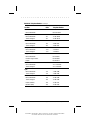
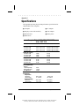
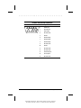
. . . . . . . . . . . . . . . . . . . . . . . . .
Extended Life Nickel Metal Hydride Battery Pack
Dimensions
Height
Length
Width
Weight
Energy
Nominal Open Circuit Voltage
Rated Capacity
Standard Recharge Rate
Environmental Requirements
Operating temperatures
Storage temperatures
No time limit
Not longer than 3 months
U.S.
Metric
0.724 in
8.07 in
2.04 in
1.09 lb
1.84 cm
20.5 cm
5.18 cm
0.495 Kg
10.8 V dc
2400 or 2800 mAh
27 W Maximum
7 W Minimum
50°F to 95°F
10°C to 35°C
-4°F to 86°F
-4°F to 104°F
-4°F to 122°F
-20°C to 30°C
-20°C to 40°C
-20°C to 50°C
Specifications
Part Number: 262446-002 File Name: APPA.DOC Writer: Johnnie Abercrombie
Saved by: Johnnie Abercrombie Saved Date 09/19/96 1:42 PM, 3:11 PM
A-7
Part Number: 262446-002 File Name: APPA.DOC Writer: Johnnie Abercrombie
Saved by: Johnnie Abercrombie Saved Date 09/19/96 1:42 PM, 3:11 PM
. . . . . . . . . . . . . . . . . . . . . . . . .
Appendix B
POST Error Messages
The following table lists selected error codes that you may
encounter during the Power-On Self-Test (POST). The POST
occurs after you first turn on the computer. A successful POST is
followed by one or two short beeps.
If one of the error codes listed below is displayed on the screen
during POST, follow the instructions in the recommended action. If
you receive an error code not listed here, contact your Compaq
authorized service provider. You also may wish to run Computer
Checkup; see Chapter 10, "Diagnostics," for information about this
utility.
POST Error Codes
Error
Code
Beeps
Probable
Cause
Action
162-System
Options Error
2S
Configuration
error
Run Computer Checkup
(See Chapter 10.)
162-System
Options Not Set
2S
Configuration
incorrect
Run Computer Checkup
(See Chapter 10.)
162-System
Options Not Set
(Run SETUP)
2S
CMOS reflects
that an invalid
configuration
has been set
Run Computer Checkup
(See Chapter 10.)
163-Time & Date
Not Set
2S
Invalid time
Run Computer Checkup
(See Chapter 10.)
164-Memory
Increase Detected
2S
Discrepancy in
No action is required
the memory size
found compared
to the one stored
in CMOS
Continued
POST Error Messages
Part Number: 262446-001 Writer: Dianne Fielden Saved by: JohnnieA
Saved Date: 02/29/96 11:04 AM 12:17 PM File Name: APPB.DOC
B-1
. . . . . . . . . . . . . . . . . . . . . . . . .
Post Error Codes Continued
Error
Code
B-2
Beeps
Probable
Cause
Action
164-Memory
Decrease Detected
2S
Discrepancy in
the memory
size found
compared to
the one stored
in CMOS
If you removed a memory
expansion board prior to
turning on the computer,
no action is required.
Otherwise, contact a
Compaq authorized
service provider.
208-Invalid
Memory
Expansion Board
None
The memory
expansion
board is an
invalid type
Replace memory
expansion board.
605-Diskette Drive
Error
None
Mismatch in
drive type
Run Computer Checkup.
(See Chapter 10.)
605-Diskette Drive
Type Error (Run
SETUP)
2S
Disk type does
not match the
drive
Run Computer Checkup.
(See Chapter 10.)
1150-COMM Port
Configuration Error
2S
Added or removed Run Computer Checkup.
modem, or serial (See Chapter 10.)
interface board
Audible
1S
Power-on
successful
None.
Audible
2S
Power-on
successful
None.
(Resume=
"F1" Key)
None
As indicated to
continue
Press F1 key.
POST Error Messages
Part Number: 262446-001 Writer: Dianne Fielden Saved by: JohnnieA
Saved Date: 02/29/96 11:04 AM 12:17 PM File Name: APPB.DOC
. . . . . . . . . . . . . . . . . . . . . . . . .
Appendix C
Connector Pin Assignments
Parallel Connector
13
25
10
11
12
24
Pin
1
2
3
4
5
6
7
8
9
10
11
12
13
14
15
16
17
18
19
20
21
22
23
24
25
23
9
22
8
21
20
5
6
7
19
18
3
4
17
16
1
2
15
14
Signal
Strobe*
Data Bit 0
Data Bit 1
Data Bit 2
Data Bit 3
Data Bit 4
Data Bit 5
Data Bit 6
Data Bit 7
Acknowledge*
Busy
Paper Out
Select
Auto Linefeed*
Error*
Initialize Printer*
Select In*
Ground
Ground
Ground
Ground
Ground
Ground
Ground
Ground
* = Active low
Connector Pin Assignments
Part Number:262446-001 Writer: Dianne Fielden Saved by: JohnnieA
Saved Date: 02/26/96 1:26 PM 12:17 PM File Name: APPC.DOC
C-1
. . . . . . . . . . . . . . . . . . . . . . . . .
Serial Connector
Connector
2
1
6
7
5
4
3
8
Pin
Signal
1
Carrier Detect
2
Receive Data
3
Transmit Data
4
Data Terminal Ready
5
Ground
6
Data Set Ready
7
Ready to Send
8
Clear to Send
9
Ring Indicator
9
Keyboard/Mouse Connector
Connector
5
6
4
3
2
C-2
1
Pin
Signal
1
Data
2
Reserved
3
Ground
4
+ 5V
5
Clock
6
Reserved
Connector Pin Assignments
Part Number:262446-001 Writer: Dianne Fielden Saved by: JohnnieA
Saved Date: 02/26/96 1:26 PM 12:17 PM File Name: APPC.DOC
. . . . . . . . . . . . . . . . . . . . . . . . .
External VGA Monitor Connector
Connector
5
Pin
4
3
14
13
10
15
1
2
8
6
7
12
11
Signal
1
Red Analog
2
Green Analog
3
Blue Analog
4
Not Connected
5
Ground
6
Ground Analog
7
Ground Analog
8
Ground Analog
9
Not Connected
10
Ground
11
Not Connected
12
Not Connected
13
Horizontal Synch
14
Vertical Synch
15
Not Connected
Connector Pin Assignments
Part Number:262446-001 Writer: Dianne Fielden Saved by: JohnnieA
Saved Date: 02/26/96 1:26 PM 12:17 PM File Name: APPC.DOC
C-3
. . . . . . . . . . . . . . . . . . . . . . . . .
PC Card (PCMCIA) Connector
Pin
Signal
Pin
Signal
1
2
3
4
5
6
7
8
9
10
Ground
Data bit 3
Data bit 4
Data bit 5
Data bit 6
Data bit 7
Card enable 1
Address bit 10
Output enable
Address bit 11
24
25
26
27
28
29
30
31
32
33
11
12
13
14
15
16
Address bit 9
Address bit 8
Address bit 13
Address bit 14
Program/Write enable
Ready or busy/
Interrupt request
Power
Programming and
peripheral supply 1
Address bit 16
Address bit 15
Address bit 12
Address bit 7
Address bit 6
34
35
36
37
38
39
Address bit 5
Address bit 4
Address bit 3
Address bit 2
Address bit 1
Address bit 0
Data bit 0
Data bit 1
Data bit 2
Write protect/IO
Port is 16-bit
Ground
Ground
Card detect 1
Data bit 11
Data bit 12
Data bit 13
40
41
Data bit 14
Data bit 15
42
43
44
45
46
Card enable 2
Refresh
IO Read
IO Write
Address bit 17
17
18
19
20
21
22
23
Continued
C-4
Connector Pin Assignments
Part Number:262446-001 Writer: Dianne Fielden Saved by: JohnnieA
Saved Date: 02/26/96 1:26 PM 12:17 PM File Name: APPC.DOC
. . . . . . . . . . . . . . . . . . . . . . . . .
PC Card (PCMCIA) Connector Continued
Pin
Signal
Pin
Signal
47
Address bit 18
58
Card reset
48
Address bit 19
59
Extend bus cycle
49
Address bit 20
60
Input port acknowledge
50
Address bit 21
61
51
Power
62
Register select and IO
enable
Battery voltage detect
2/Audio digital waveform
52
Programming and
peripheral supply 2
63
Battery voltage detect
1/Card status changed
53
Address bit 22
64
Data bit 8
54
Address bit 23
65
Data bit 9
55
Address bit 24
66
Data bit 10
Address bit 25
Reserved
67
Card detect 2
68
Ground
56
57
Connector Pin Assignments
Part Number:262446-001 Writer: Dianne Fielden Saved by: JohnnieA
Saved Date: 02/26/96 1:26 PM 12:17 PM File Name: APPC.DOC
C-5
Part Number:262446-001 Writer: Dianne Fielden Saved by: JohnnieA
Saved Date: 02/26/96 1:26 PM 12:17 PM File Name: APPC.DOC
. . . . . . . . . . . . . . . . . . . . . . . . .
Appendix D
Power Cord Set
Requirements
The wide-range input feature of your AC Adapter permits it to
operate from any line voltage between 100 to 240 volts AC.
The power plug or power cord set (appliance coupler, flexible cord,
and wall plug) you received with your AC Adapter meets the
requirements for use in the country where you purchased your
computer.
Power cord sets for use in other countries must meet the
requirements of the country where you use the AC Adapter. For
more information on power cord set requirements, contact your
Compaq authorized dealer.
General Requirements
The requirements listed below are applicable to all countries:
1. The length of the power cord set must be at least 6.00 feet (1.8
m) and a maximum of 9.75 feet (3.0 m).
2. All power cord sets must be approved by an acceptable
accredited agency responsible for evaluation in the country
where the power cord set will be used.
3. The power cord set must have a minimum current capacity of
2.5A and a nominal voltage rating of 125 or 250 volts AC, as
required by each country’s power system.
4. The appliance coupler must meet the mechanical configuration
of an EN 60 320/IEC 320 Standard Sheet C7 connector, for
mating with appliance inlet on the AC Adapter.
Power Cord Set Requirements
Part Number: 262446-001 Writer: Dianne Fielden Saved by: JohnnieA
Saved Date: 02/26/96 1:22 PM 12:18 PM File Name: APPD.DOC
D-1
. . . . . . . . . . . . . . . . . . . . . . . . .
Country-Specific Requirements
Power Cord Set Requirements
Country
Accredited
Agency
Applicable Note
Numbers
Australia
EANSW
1
Austria
OVE
1
Belgium
CEBC
1
Canada
CSA
2
Denmark
DEMKO
1
Finland
FIMKO
1
France
UTE
1
Germany
VDE
1
Italy
IMQ
1
Japan
JIS
3
The Netherlands
KEMA
1
Norway
NEMKO
1
Sweden
SEMKO
1
Switzerland
SEV
1
United Kingdom
BSI
1
United States
UL
2
Notes:
1. Flexible cord must be <HAR> Type HO3VV-F, 2-conductor,
0.75 mm2 conductor size. Power cord set fittings (appliance
coupler and wall plug) must bear the certification mark of the
agency responsible for evaluation in the country where it will be
used.
2. Flexible cord must be Type SPT-2 or equivalent, No. 18 AWG,
2-conductor. Wall plug must be a two-pole type with a NEMA 115P (15A, 125V) configuration.
D-2
Power Cord Set Requirements
Part Number: 262446-001 Writer: Dianne Fielden Saved by: JohnnieA
Saved Date: 02/26/96 1:22 PM 12:18 PM File Name: APPD.DOC
. . . . . . . . . . . . . . . . . . . . . . . . .
3. Appliance coupler, flexible cord, and wall plug must bear a "T"
mark and registration number in accordance with the Japanese
Dentori Law. Flexible cord must be Type VFF, VSF or VTF,
2-conductor, 0.75 mm2 conductor size. Wall plug must be a twopole type with a Japanese Industrial Standard C8303 (15A,
125V) configuration.
Power Cord Set Requirements
Part Number: 262446-001 Writer: Dianne Fielden Saved by: JohnnieA
Saved Date: 02/26/96 1:22 PM 12:18 PM File Name: APPD.DOC
D-3
. . . . . . . . . . . . . . . . . . . . . . . . .
Appendix D
Power Cord Set Requirements
Part Number: 262446-001 Writer: Dianne Fielden Saved by: JohnnieA
Saved Date: 02/26/96 1:22 PM 12:18 PM File Name: APPD.DOC
D-4
. . . . . . . . . . . . . . . . . . . . . . . . .
Appendix E
Regulatory Agency
Identification Numbers
The following options have been evaluated for use with your
computer. These Compaq approved options can be identified by
their assigned series numbers that are listed below. To ensure
continued reliable and safe operation of your computer, only these
options should be used.
Regulatory Agency Identification Numbers
Options
Series Numbers
Notebook CPUs
2860, 2860A, 2860B,
2860C, 2860D, 2860E,
2860F
Notebook CPU with Display Upgrade
2860A UD, 2860B UD
Extended Life NiMH Battery Pack
2831A
Automobile Adapter
2834
AC Adapter with Power Plug
2862, 2862B
Regulatory Agency Identification Numbers
Part Number: 262446-001 Writer Dianne Fielden Saved by: JohnnieA
Saved Date: 02/29/96 11:54 AM 12:19 PM File Name: APPE.DOC
E-1
. . . . . . . . . . . . . . . . . . . . . . . . .
Appendix E
Regulatory Agency Identification Numbers
Part Number: 262446-001 Writer Dianne Fielden Saved by: JohnnieA
Saved Date: 02/29/96 11:54 AM 12:19 PM File Name: APPE.DOC
E-2
. . . . . . . . . . . . . . . . . . . . . . . . .
Index
A
AC Adapter, 2-7, 4-6, 7-3
specifications, A-6
Add New Hardware icon, 7-2
application software
installing, 6-2
AUTOEXEC.BAT, 11-18
Automobile Adapter, 7-4
specifications, A-6
B
backlight
CSTN (10.4 in), A-2
CTFT (10.4 in), A-3
battery
battery gauge indicators, 4-7
CSTN (10.4 in), A-1
CTFT (10.4 in), A-1
low-battery condition, 4-8
power requirements, A-1
problems, 11-3
battery charge indicator, 2-5
battery compartment, 2-8
opening, 4-11
battery conservation
timeouts, 4-15
battery gauge, 2-5
battery pack
approved for use, 4-12
charging, 4-13
discharging, 11-3
extending operating time, 4-9
fast charge cycles, 4-9
identifying conservation levels,
4-16
inserting, 4-12
operating temperatures, 11-5, A-7
removing, 4-10
setting conservation levels with
hotkeys, 4-17
specifications, A-7
storage temperatures for, 4-9
storing, 4-9, 11-5
trickle charge, 4-9
battery power
reading battery gauge, 4-7
beeps
identifying low-battery condition,
4-8
inserting a PC Card, 8-4
POST, B-1
removing a PC Card, 8-6
bottom panel components, 2-8
brightness
CSTN (10.4 in), A-2
CTFT (10.4 in), A-3
brightness control, 3-5
C
cable lock, 5-7
caution message described, xvi
charging battery pack, 4-13
cleaning trackball, 11-21
color palette
CSTN (10.4 in), A-2
CTFT (10.4 in), A-3
Compaq authorized dealer, reseller,
service provider
locating, 11-24
compartment
battery, 2-8
memory, 2-8
components
bottom panel, 2-8
front and side, 2-2
keyboard, 2-3
rear, 2-7
status panel, 2-4
trackball, 2-6
Index
Writer: JohnnieA - Saved by: Johnnie Abercrombie - Saved date: 04/25/96 10:08 AM
Part Number: 189164-001 - File name: INDEX.DOC
I-1
. . . . . . . . . . . . . . . . . . . . . . . . .
computer
routine care, 9-2
shipping, 9-4
travel guidelines, 9-3
computer checkup (TEST)
running, 10-2
configuration and diagnostics menu
accessing, 10-1
connectors, 2-1
AC power, 2-7
external monitor, 2-7
keyboard/mouse, 2-7, C-2
monitor, C-3
parallel, 2-7, C-1
PC Card, C-4
printer, 7-2
serial, 2-7, C-2
contrast ratio
CSTN (10.4 in), A-2
CTFT (10.4 in), A-3
controls
brightness, 3-5
contrast, 3-5
CSTN (10.4 in)
backlight, A-2
battery, A-1
brightness, A-2
color palette, A-2
contrast ratio, A-2
pixel resolution, A-2
specifications, A-1, A-2
CTFT (10.4 in)
backlight, A-3
battery, A-1
brightness, A-3
color palette, A-3
contrast ratio, A-3
pixel resolution, A-3
specifications, A-1, A-3
cursor keys, 2-4, 3-3
customer registration, 1-1
Customer Support Center
telephone number, 11-24
I-2
D
device drivers
installing, 11-8
Device Manager, 7-1, 11-8
diagnostics, 10-1
automatic, 10-3
hard drive, 10-4
memory configuration, 10-4
modem, 10-4
operating system, 10-4
printer, 10-4
processor, 10-4
prompted, 10-3
Quick Check, 10-3
ROM versions, 10-4
running
Compaq Diagnostics for
Windows, 10-5
computer checkup (TEST),
10-2
video, 10-4
diskette drive, 2-2, 2-5
specifications, A-4
display
CSTN (10.4 in), A-1
CTFT (10.4 in), A-1
problems, 11-16
reducing brightness, 4-9
disposing of used battery pack,
4-11, 4-13
drive size, A-5
drives supported, A-5
E
embedded numeric keypad, 2-4, 3-3
problems, 11-10
error codes, B-1
external monitor, 3-4, 11-17
connector, 2-7
specifications, 7-6
Index
Writer: JohnnieA - Saved by: Johnnie Abercrombie - Saved date: 04/25/96 10:08 AM
Part Number: 189164-001 - File name: INDEX.DOC
. . . . . . . . . . . . . . . . . . . . . . . . .
F
K
format conventions, xv
formatted capacity, A-5
function keys, 2-3, 3-2, 3-7
keyboard, 2-3, 3-2
problems, 11-10
keyboard/mouse
connector, 2-7, C-2
keypad
cursor movement, 2-4, 3-3
embedded numeric, 2-4, 3-3
keys
function, 3-7
G
guidelines
routine care, 9-2
shipping, 9-4
travel, 9-3
M
H
handle
attaching, 2-2
hard drive, 2-5
diagnostics, 10-4
problems, 11-7
removing, 11-7
Hibernation, 2-3, 3-2, 4-4
exiting, 4-4
extending battery pack operating
time, 4-9
how to turn off, 4-15
initiating, 4-4
hotkeys
controlling display, 11-17
identifying, 3-4
memory
configuration/diagnostics, 10-4
problems, 11-11
upgrading, 6-1
memory compartment, 2-8
messages
error, B-1
on screen examples, 11-2
modem
diagnostics, 10-4
monitor
connecting, 7-6
connector, C-3
external, 11-17
self-test, 11-11
O
I
indicators
battery charge, 2-5
battery gauge, 2-5
diskette drive, 2-5
hard drive, 2-5
power/standby, 2-5
status panel, 2-4
information
Customer Support Center, 11-24
service, 11-24
INSPECT utility, 10-4
online references, 1-1
Compaq Dictionary, 1-2
Compaq User's Guide, 1-1
Microsoft Windows 95, 1-1
product tutorial, 1-2
Safety & Comfort Guide, 1-1
Windows interface, 1-2
operating system
diagnostics, 10-4
Index
Writer: JohnnieA - Saved by: Johnnie Abercrombie - Saved date: 04/25/96 10:08 AM
Part Number: 189164-001 - File name: INDEX.DOC
I-3
. . . . . . . . . . . . . . . . . . . . . . . . .
P
parallel connector, 2-7, C-1
passwords, 5-2
power on password, 5-2
setup password, 5-4
PC Card
compatibility, 8-3
connector, C-4
inserting, 8-1, 8-4
PC Card Solution logo, 8-3
problems, 11-12
removing, 8-6
slots, 2-2
types, 8-1, 8-2
PC Card release lever, 8-6
PCMCIA. See PC Card
PCMCIA. See PC Card, 8-1
pixel resolution
CSTN (10.4 in), A-2
CTFT (10.4 in), A-3
POST. See Power-On Self Test, B-1
power
AC Adapter with power cord, 4-6
how to turn off, 4-5
how to turn off in system lock-up,
2-3, 3-2, 4-5
problems, 11-14
when to turn off, 4-5
power button, 2-3, 3-2, 4-2
power conservation, 3-5
power cord requirements, D-1
power properties, 4-14
how to get to it, 4-14
Power-On Self-Test (POST), 10-1,
B-1
power/standby indicator, 2-5
printed references, 1-1
Backup Diskettes Card, 1-1
Beyond Setup, 1-1
customer registration, 1-1
Introducing MS Windows 95, 1-1
Quick Setup, 1-1
Safety & Comfort Guide, 1-1
warranty, 1-1
I-4
printer
connecting, 7-2
diagnostics, 10-4
problems, 11-15
self-test, 11-15
Printing the screen, 3-7
problem solving. See
troubleshooting, 11-1
processor
diagnostics, 10-4
Q
QuickBlank, 3-5, 5-5
QuickLock, 3-5, 5-5
R
RAM. See random access memory,
6-3
random access memory
expanding, 6-3
real-time clock battery, 11-4
recharging battery pack, 4-13
references
online, 1-1
printed, 1-1
ROM version
diagnostics, 10-4
S
ScanDisk, 11-6, 11-7
screen
messages, 11-2
problems, 11-16
sector interleave, A-5
security management utility
disabling password, 11-24
serial connector, 2-7, C-2
service information, 11-24
shipping computer, 9-4
software
application problems, 11-18
installing, 6-2
Index
Writer: JohnnieA - Saved by: Johnnie Abercrombie - Saved date: 04/25/96 10:08 AM
Part Number: 189164-001 - File name: INDEX.DOC
. . . . . . . . . . . . . . . . . . . . . . . . .
sound
problems, 11-18
specifications
AC Adapter, A-6
Automobile Adapter, A-6
battery pack, A-7
CSTN (10.4 in), A-2
CTFT (10.4 in), A-3
diskette drive, A-4
monitor, 7-6
Standby, 2-3, 2-5, 3-2
exiting, 4-3
extending battery operating time,
4-9
initiating, 4-3
status panel, 2-3, 3-2
indicators, 2-4, 2-5
storage temperatures for battery
pack, 11-5
Suspend. See Standby, 4-3
system configuration
changing, 10-1
errors, 10-1
T
telephone numbers
Customer Support Center, 11-24
temperatures
battery pack, 11-5
operating battery pack, A-7
storing battery pack, 4-9, 11-5,
A-7
TEST (computer checkup) utility,
10-2
timeouts
battery conservation, 4-15
how to use, 4-15
trackball, 2-4, 2-6, 3-3, 7-1
cleaning, 11-21, 11-22
connecting, 7-7
problems, 11-19
transfer rate, A-5
travel guidelines, 9-3
trickle charge, 4-9
troubleshooting
battery, 11-3
cleaning trackball, 11-21
diskette/diskette drive, 11-6
display screen, 11-16
hard drive, 11-7
hardware installation, 11-8
helpful hints, 11-1
keyboard/embedded numeric
keypad, 11-10
memory, 11-11
minor problems, 11-2
monitor self-test, 11-11
PC Card, 11-12
power, 11-14
printer, 11-15
software applications, 11-18
sound, 11-18
trackball/mouse, 11-19
U
upgrading
memory, 6-1
V
video
diagnostics, 10-4
view system information
(INSPECT)
running, 10-4
W
warning message described, xvi
warranty, 1-1
Index
Writer: JohnnieA - Saved by: Johnnie Abercrombie - Saved date: 04/25/96 10:08 AM
Part Number: 189164-001 - File name: INDEX.DOC
I-5
Writer: JohnnieA - Saved by: Johnnie Abercrombie - Saved date: 04/25/96 10:08 AM
Part Number: 189164-001 - File name: INDEX.DOC