1
AIR-COOLED LIQUID CHILLERS
HERMETIC SCROLL
INSTALLATION, OPERATION, Maintenance
Supersedes 150.62-NM8 (1108)
Form 150.62-NM8 (410)
035-22320-000
YCAL0014E_ - YCAL0134E_
AIR COOLED SCROLL CHILLERS
STYLE C
WITH IPU II AND I/O BOARDS
60 Hz
29224(R)A
R-22 & HFC-407C
200-3-60
230-3-60
380-3-60
460-3-60
575-3-60
MODELS ONLY
Standard, Glycol & Metric Models, Combined
FORM 150.62-NM8 (410)
IMPORTANT!
Read BEFORE PROCEEDING!
GENERAL SAFETY GUIDELINES
This equipment is a relatively complicated apparatus.
During installation, operation, maintenance or service,
individuals may be exposed to certain components or
conditions including, but not limited to: refrigerants,
oils, materials under pressure, rotating components,
and both high and low voltage. Each of these items
has the potential, if misused or handled improperly, to
cause bodily injury or death. It is the obligation and
responsibility of operating/service personnel to identify
and recognize these inherent hazards, protect themselves,
and proceed safely in completing their tasks. Failure to
comply with any of these requirements could result in
serious damage to the equipment and the property in
which it is situated, as well as severe personal injury or
death to themselves and people at the site.
This document is intended for use by owner-authorized
operating/service personnel. It is expected that this
individual possesses independent training that will
enable them to perform their assigned tasks properly
and safely. It is essential that, prior to performing any
task on this equipment, this individual will have read
and understood this document and any referenced
materials. This individual will also be familiar with and
comply with all applicable governmental standards and
regulations pertaining to the task in question.
SAFETY SYMBOLS
The following symbols are used in this document to alert the reader to areas of potential hazard:
DANGER indicates an imminently
hazardous situation which, if not
avoided, will result in death or serious injury.
CAUTION identifies a hazard which
could lead to damage to the machine,
damage to other equipment and/or
environmental pollution. Usually an
instruction will be given, together with
a brief explanation.
WARNING indicates a potentially
hazardous situation which, if not
avoided, could result in death or serious injury.
NOTE is used to highlight additional
information which may be helpful to
you.
External wiring, unless specified as an optional connection in the manufacturer’s product
line, is not to be connected inside the micro panel cabinet. Devices such as relays, switches,
transducers and controls may not be installed inside the micro panel. No external wiring
is allowed to be run through the micro panel. All wiring must be in accordance with Johnson Controls published specifications and must be performed only by qualified Johnson
Controls personnel. Johnson Controls will not be responsible for damages/problems resulting from improper connections to the controls or application of improper control signals.
Failure to follow this will void the manufacturer’s warranty and cause serious damage to
property or injury to persons.
2
JOHNSON CONTROLS
FORM 150.62-NM8 (410)
CHANGEABILITY OF THIS DOCUMENT
In complying with Johnson Controls policy for
continuous product improvement, the information
contained in this document is subject to change without
notice. While Johnson Controls makes no commitment
to update or provide current information automatically
to the manual owner, that information, if applicable, can
be obtained by contacting the nearest Johnson Controls
Engineered Systems Service office.
JOHNSON CONTROLS
It is the responsibility of operating/service personnel
to verify the applicability of these documents to the
equipment in question. If there is any question in
the mind of operating/service personnel as to the
applicability of these documents, then prior to working
on the equipment, they should verify with the owner
whether the equipment has been modified and if current
literature is available.
3
FORM 150.62-NM8 (410)
THIS PAGE INTENTIONALLY LEFT BLANK
4
JOHNSON CONTROLS
FORM 150.62-NM8 (410)
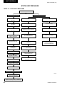
TABLE OF CONTENTS
SECTION 1 - INSTALLATION............................................................................................................19
INSTALLATION CHECK LIST.......................................................................................................................19
HANDLING....................................................................................................................................................19
INSPECTION.................................................................................................................................................19
LOCATION AND CLEARANCES..................................................................................................................19
Foundation...............................................................................................................................................20
Ground Level Locations.........................................................................................................................20
Rooftop Locations..................................................................................................................................20
Noise Sensitive Locations......................................................................................................................20
SPRING ISOLATORS (OPTIONAL)..............................................................................................................20
COMPRESSOR MOUNTING.........................................................................................................................20
REMOTE COOLER OPTION.........................................................................................................................20
CHILLED WATER PIPING.............................................................................................................................20
General . ..................................................................................................................................................20
WIRING..........................................................................................................................................................21
Field Wiring..............................................................................................................................................21
Evaporator Pump Start Contacts...........................................................................................................22
System Run Contacts.............................................................................................................................22
Alarm Status Contacts............................................................................................................................22
Remote Start/Stop Contacts..................................................................................................................22
Remote Emergency Cutoff.....................................................................................................................22
PWM Input................................................................................................................................................22
Load Limit Input......................................................................................................................................22
Flow Switch Input....................................................................................................................................22
Compressor Heaters...............................................................................................................................22
single-point supply connection – terminal block, non-fused disconnect
switch or circuit breaker (0014 - 0080)..........................................................................................23
multiple point power supply connection – terminal block (0040 - 0080)........................24
multiple point power supply connection – terminal block,
non-fused disconnect switches or circuit breakers (0090 - 0134)...................................25
single-point SUPPLY connection – terminal block or non-fused disconnect
switch to individual system circuit breakers (0090 - 0134)..................................................26
control WIRING.......................................................................................................................................27
ELECTRICAL NOTES and legend...........................................................................................................28
JOHNSON CONTROLS
5
FORM 150.62-NM8 (410)
TABLE OF CONTENTS (CONT'D)
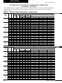
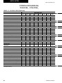
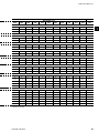
ELECTRICAL DATA......................................................................................................................................29
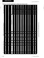
Single-Point Power Supply Connections – YCAL0014E_ - YCAL0034E_..........................................30
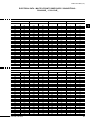
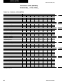
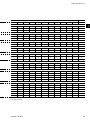
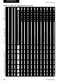
Electrical Data – Dual Point Power Supply Connections – YCAL0040E_ - YCAL0080E_................32
Electrical Data – Dual Point Power Supply Connections – YCAL0040E_ - YCAL0080E_................33
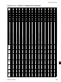
Electrical Data – Single Point Power Supply Connections – YCAL0040E_ - YCAL0080E_.............34
Electrical Data – Single Point Power Supply Connections – YCAL0040E_ - YCAL0080E_.............35
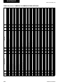
Electrical Data – Multiple Point Power Supply Connections – YCAL0090E_ - YCAL0134E_...........36
Electrical Data – Multiple Point Power Supply Connections – YCAL0090E_ - YCAL0134E_...........37
Electrical Data – Single Point Power Supply Connections With Individual
System Circuit Breakers – YCAL0090E_ - YCAL0134E_.....................................................................38
Electrical Data – Single Point Power Supply Connections With Individual
System Circuit Breakers – YCAL0090E_ - YCAL0134E_.....................................................................39
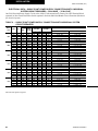
OPERATIONAL LIMITATIONS (ENGLISH)...................................................................................................40
Voltage Limitations.................................................................................................................................40
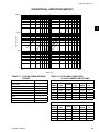
operational limitations (METRIC).....................................................................................................42
Voltage Limitations.................................................................................................................................42
PHYSICAL DATA (ENGLISH) YCAL0014E_ - YCAL0134E_.......................................................................44
PHYSICAL DATA (METRIC) YCAL0014E_ - YCAL0134E_.........................................................................46
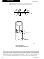
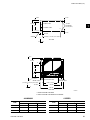
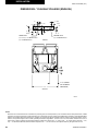
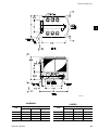
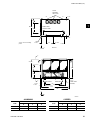
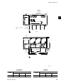
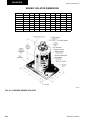
DIMENSIONS AND CLEARANCES..............................................................................................................48
Dimensions - YCAL0014-YCAL0020 (English).....................................................................................48
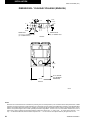
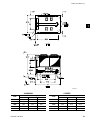
Dimensions - YCAL0024-YCAL0034 (English).....................................................................................50
Dimensions - YCAL0040-YCAL0060 (English).....................................................................................52
Dimensions - YCAL0064-YCAL0080 (English).....................................................................................54
Dimensions - YCAL0090-YCAL0094 (English).....................................................................................56
Dimensions - YCAL0104 (English)........................................................................................................58
Dimensions - YCAL0114 - YCAL0134 (English)...................................................................................60
Dimensions - YCAL0014-YCAL0020 (SI)...............................................................................................62
Dimensions - YCAL0024-YCAL0034 (SI)...............................................................................................64
Dimensions - YCAL0040-YCAL0060 (SI)...............................................................................................66
Dimensions -YCAL0064-YCAL0080 (SI)................................................................................................68
Dimensions - YCAL0090-YCAL0094 (SI)...............................................................................................70
Dimensions - YCAL0104 (SI)..................................................................................................................72
Dimensions - YCAL0114 - YCAL0134 (SI).............................................................................................74
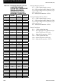
EQUIPMENT PRE-STARTUP and STARTUP CHECKLIST........................................................................76
Pre-Startup...............................................................................................................................................76
Startup......................................................................................................................................................77
Checking Superheat and Subcooling...................................................................................................78
Leak Checking.........................................................................................................................................79
UNIT OPERATING SEQUENCE....................................................................................................................80
6
JOHNSON CONTROLS
FORM 150.62-NM8 (410)
TABLE OF CONTENTS (CONT'D)
SECTION 2 - UNIT CONTROLS.........................................................................................................81
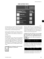
INTRODUCTION............................................................................................................................................81
IPU II AND I/O BOARDS...............................................................................................................................81
Unit Switch................................................................................................................................................82
Display........................................................................................................................................................82
Keypad.........................................................................................................................................................82
Battery Back-up.....................................................................................................................................82
Transformer ..........................................................................................................................................82
Single System Select and Programming # of Compressors...............................................82
STATUS KEY................................................................................................................................................83
General Status Messages.......................................................................................................................83
Fault Status Messages...........................................................................................................................85
Unit Warning............................................................................................................................................87
STATUS KEY MESSAGES............................................................................................................................88
DISPLAY/PRINT KEYS.................................................................................................................................89
Oper Data Key.........................................................................................................................................89
Oper Data Quick Reference List............................................................................................................92
Print Key..................................................................................................................................................93
Operating Data Printout..........................................................................................................................93
History Printout.......................................................................................................................................94
History Displays......................................................................................................................................94
Software Version.....................................................................................................................................97
ENTRY KEYS.................................................................................................................................................98
Up and Down Arrow Keys......................................................................................................................98
Enter/Adv Key..........................................................................................................................................98
SETPOINTS KEYS........................................................................................................................................99
Cooling Setpoints...................................................................................................................................99
Leaving Chilled Liquid Control..............................................................................................................99
Return Chilled Liquid Control..............................................................................................................100
Schedule/Advance Day Key.................................................................................................................100
Program Key..........................................................................................................................................102
UNIT KEYS .................................................................................................................................................107
Options Key...........................................................................................................................................107
CLOCK......................................................................................................................................................... 111
SECTION 3 - UNIT OPERATION......................................................................................................113
Capacity Control................................................................................................................................. 113
Suction Pressure Limit Controls................................................................................................. 113
Discharge Pressure Limit Controls........................................................................................... 113
Leaving Chilled Liquid Control..................................................................................................... 113
Leaving Chilled Liquid Control Override to Reduce Cycling............................................................ 114
RETURN CHILLED LIQUID CONTROL...................................................................................................... 114
system lead/lag................................................................................................................................... 116
compressor lead/lag........................................................................................................................ 116
JOHNSON CONTROLS
7
FORM 150.62-NM8 (410)
TABLE OF CONTENTS (CONT'D)
anti-recycle timer.............................................................................................................................. 116
anti-coincidence timer...................................................................................................................... 116
Evaporator Pump Control.............................................................................................................. 117
Evaporator Heater Control.......................................................................................................... 117
PUMPDOWN CONTROL............................................................................................................................. 117
Electronic expansion valve (EEV)................................................................................................. 117
General................................................................................................................................................... 117
MOP Feature.......................................................................................................................................... 117
Valve Preheat......................................................................................................................................... 117
Inputs..................................................................................................................................................... 117
Outputs.................................................................................................................................................. 118
Program................................................................................................................................................. 118
Safeties.................................................................................................................................................. 118
Condenser Fan Control (YCAL0014 through YCAL0080 chillers)..................................... 118
condenser fan control (YCAL0090 through YCAL0134)........................................................ 118
Low Ambient Condenser Fan Control (YCAL0014 through YCAL0080).............................. 118
condenser fan control................................................................................................................... 119
YCAL0014 - YCAL0080......................................................................................................................... 119
YCAL0090 – YCAL0104.........................................................................................................................121
YCAL0114 – YCAL0134.........................................................................................................................122
Load Limiting..........................................................................................................................................123
Compressor Run Status....................................................................................................................123
Alarm Status.........................................................................................................................................123
EMS-PWM REMOTE TEMPERATURE RESET..........................................................................................124
BAS/EMS TEMPERATURE RESET OPTION.............................................................................................124
SECTION 4 - SERVICE AND TROUBLESHOOTING......................................................................127
Clearing History Buffers................................................................................................................127
Software Version................................................................................................................................127
Service Mode..........................................................................................................................................127
Service Mode – Outputs.......................................................................................................................127
Service Mode – Chiller Configuration.................................................................................................127
Service Mode – Inputs..........................................................................................................................128
Control Inputs/Outputs...................................................................................................................129
Checking Inputs and Outputs..............................................................................................................131
KEYPAD.......................................................................................................................................................135
Parts.......................................................................................................................................................136
Assembly and Wiring............................................................................................................................136
Obtaining a Printout..............................................................................................................................136
TROUBLESHOOTING CHARTS.................................................................................................................137
8
JOHNSON CONTROLS
FORM 150.62-NM8 (410)
TABLE OF CONTENTS (CONT'D)
SECTION 5 - MAINTENANCE..........................................................................................................141
Important................................................................................................................................................141
Compressors.........................................................................................................................................141
Oil Level check......................................................................................................................................141
Oil Analysis............................................................................................................................................141
Condenser Fan Motors.....................................................................................................................141
Condenser Coils..................................................................................................................................141
Operating Parameters......................................................................................................................141
On-Board Battery Back-Up..............................................................................................................141
Overall Unit Inspection....................................................................................................................141
BACNET, MODBUS AND YORKTALK 2 COMMUNICATIONS..................................................................142
Micro Panel Connections.....................................................................................................................143
BACnet and Modbus Communications...............................................................................................145
Communications Data Map Notes.......................................................................................................145
Yorktalk 2 Communications.................................................................................................................149
SECTION 6 - WIRING DIAGRAMS..................................................................................................153
YCAL0014E_ – YCAL0030E_.....................................................................................................................153
YCAL0034E_...............................................................................................................................................159
YCAL0040E_ – YCAL0060E_.....................................................................................................................165
YCAL0064E_ – YCAL0080E_.....................................................................................................................172
YCAL0090E_ – YCAL0094E_.....................................................................................................................179
YCAL0104E_ ..............................................................................................................................................186
YCAL0114E_ – YCAL0134E_.....................................................................................................................193
SECTION 7 - ISOLATOR DATA........................................................................................................201
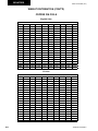
WEIGHT DISTRIBUTION............................................................................................................................201
Aluminum Fin Coils..............................................................................................................................201
Copper Fin Coils...................................................................................................................................202
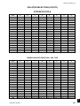
ISOLATOR SELECTIONS...........................................................................................................................203
Aluminum Fin Coils..............................................................................................................................203
Copper Fin Coils...................................................................................................................................205
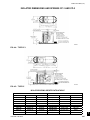
ISOLATOR DIMENSIONS and Springs CP-1 AND CP-2.....................................................................207
Isolator Spring Identification Table.....................................................................................................207
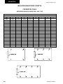
Seismic ISOLATOR DIMENSIONS...........................................................................................................208
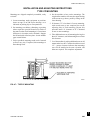
INSTALLATION AND ADJUSTING INSTALLATIONSTYPE CP MOUNTING............................................209
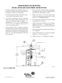
AEQM SPRING-FLEX MOUNTING.............................................................................................................210
INSTALLATION AND ADJUSTMENT INSTRUCTIONS.............................................................................210
JOHNSON CONTROLS
9
FORM 150.62-NM8 (410)
THIS PAGE INTENTIONALLY LEFT BLANK
10
JOHNSON CONTROLS
FORM 150.62-NM8 (410)
LIST OF TABLES
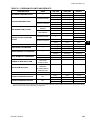
table 1 – MICRO PANEL POWER SUPPLY............................................................................................29
table 2 – SINGLE-POINT POWER supply...........................................................................................30
table 3 – DUAL POINT POWER supply connections...................................................................32
table 4 – SINGLE POINT POWER supply connections................................................................34
table 5 – MULTIPLE POINT POWER supply connections............................................................36
table 6 – S
INGLE POINT POWER supply connections with individual
system circuit breakers...............................................................................................38
table 7 – TEMPERATURES AND FLOWS..............................................................................................40
table 8 – VOLTAGE limitations..........................................................................................................40
table 9 – C
OOLER PRESSURE DROP CURVES...................................................................................41
table 10 – E
THYLENE / PROPYLENE GLYCOL CORRECTION FACTORS..........................................41
table 11 – TEMPERATURES AND FLOWS...............................................................................................42
table 12 – VOLTAGE LIMITATIONS..........................................................................................................42
table 13 – COOLER PRESSURE DROP CURVES...................................................................................43
table 14 – ETHYLENE / PROPYLENE GLYCOLCORRECTION FACTORS............................................43
table 15 – PHYSICAL DATA (ENGLISH)...................................................................................................44
table 16 – PHYSICAL DATA (METRIC).....................................................................................................46
TABLE 17 - SETPOINTS ENTRY LIST.........................................................................................................77
table 18 – STATUS KEY MESSAGES.......................................................................................................88
table 19 – OPERATION DATA...................................................................................................................92
table 20 – COOLING SETPOINTS, Programmable Limits and Defaults................................101
table 21 – PROGRAM KEY LIMITS AND DEFAULTS............................................................................105
table 22 – SETPOINTS QUICK REFERENCE LIST................................................................................106
table 23 – UNIT KEYS PROGRAMMING QUICK REFERENCE LIST.................................................... 112
table 24 – Compressor Staging for Return Water Control............................................ 115
table 25 – Return Chilled Liquid Control for 5 & 6 Compressors (7 & 8 steps)......... 115
table 26 – Return Chilled Liquid Control for 4 Compressors (6 steps)...................... 116
table 27 – YCAL0014 THROUGH YCAL0080 Condenser Fan Control Using
Outdoor Ambient Temperature and Discharge Pressure. .......................... 119
table 28 – YCAL0014 THROUGH YCAL0080 Condenser Fan Control Using
Discharge Pressure Only...........................................................................................120
table 29 – YCAL0014 - ycal0080 Low Ambient Condenser Fan Control –
Discharge Pressure Control...................................................................................120
table 30 – YCAL0090 - YCAL0104 Condenser Fan Control ......................................................121
table 31 – YCAL0114 - ycal0134 Condenser Fan Control ......................................................122
table 32 – Compressor Operation – Load Limiting.................................................................123
table 33 – I/O BOARD DIGITAL Inputs................................................................................................129
table 34 – I/O BOARD Analog Inputs...............................................................................................129
table 35 – I/O BOARD DIGITAL Outputs............................................................................................129
table 36 – I/O BOARD analog outputs...........................................................................................129
table 37 – Outdoor Air Sensor Temperature/Voltage/ Resistance Correlation.....131
JOHNSON CONTROLS
11
FORM 150.62-NM8 (410)
LIST OF TABLES (CONT'D)
table 38 – E
NTERING/LEAVING CHILLED LIQUID TEMP. sensor, cooler inlet
Temperature SENSOR, and suction temperature sensor:
TEMPERATURE/VOLTAGE/RESISTANCE CORRELATION................................................132
table 39 – Keypad Pin Assignment Matrix...................................................................................135
table 40 – troubleshooting............................................................................................................137
table 41 – minimum, maximum and default values...................................................................143
table 42 – VALUES REQUIRED FOR BAS COMMUNICATION.............................................................144
TABLE 43 – REAL TIME ERROR NUMBERS............................................................................................144
TABLE 44 - BACNET AND MODBUS COMMUNICATIONS DATA MAP...................................................146
TABLE 45 - YorkTalk 2 COMMUNICATIONS DATA MAP.....................................................................150
12
JOHNSON CONTROLS
FORM 150.62-NM8 (410)
LIST OF FIGURES
Fig. 1 – REFRIGERANT FLOW DIAGRAM................................................................................................17
Fig. 2 – single-point supply connection – terminal block, non-fused
disconnect switch or circuit breaker (0014 - 0080).................................................23
Fig. 3 – multiple point power supply connection – terminal block (0040 - 0080)........24
Fig. 4 – multiple point power supply connection – terminal block,
non-fused disconnect switches or circuit breakers (0090 - 0134)...................25
Fig. 5 – optional single-point power wiring.............................................................................26
Fig. 6 – control wiring......................................................................................................................27
fig. 7 – setpoint adjust.................................................................................................................... 114
Fig. 8 – L
EAVING WATER TEMPERATURE CONTROL example....................................................... 114
Fig. 9 – YCAL0014 THROUGH YCAL0080 Fan Location (Typical)............................................... 119
Fig. 10 – YCAL0090 through YCAL0104 Fan Location..................................................................121
Fig. 11 – YCAL0114 – ycal0134 Fan Location...................................................................................122
FIG. 12 – F
IELD AND FACTORY ELECTRICAL CONNECTIONSOPTIONAL REMOTE
TEMPERATURE RESET BOARD................................................................................................125
Fig. 13 – I/O BOARD LAYOUT...................................................................................................................130
Fig. 14 – i/o board Relay Contact Architecture......................................................................134
Fig. 15 – Printer to I/O Board Electrical Connections........................................................136
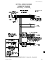
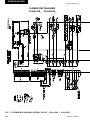
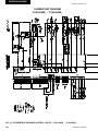
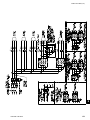
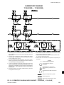
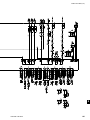
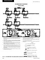
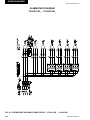
fig. 16 – elementary diagram, power circuit – ycal0014e_ - ycal0030e_........................153
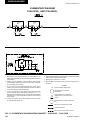
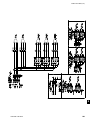
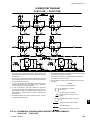
fig. 17 – elementary diagram, control circuit – ycal0014e_ - ycal0030e_....................154
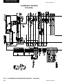
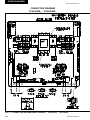
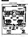
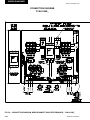
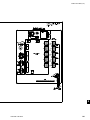
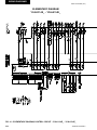
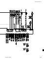
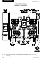
fig. 18 – connection diagram, middle market – ycal0014e_ - ycal0030e_.......................156
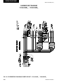
fig. 19 – elementary diagram, middle market – ycal0014e_ - ycal0030e_.......................158
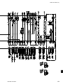
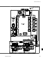
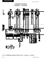
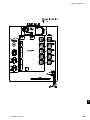
fig. 20 – elementary diagram, power circuit – ycal0034e_.................................................159
fig. 21 – elementary diagram, middle market – ycal0034e_ ...............................................160
fig. 22 – connection diagram, middle market – ycal0034e_.................................................162
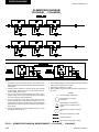
fig. 23 – elementary diagram, midlle market – ycal0034e_.................................................164
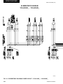
fig. 24 – elementary diagram, midlle market – ycal0040e_ - ycal0060e_........................165
fig. 25 – elementary diagram, control circuit – ycal0040e_ - ycal0060e_....................166
fig. 26 – elementary diagram, power circuit – ycal0040e_ - ycal0060e_........................168
fig. 27 – connection diagram, middle market – ycal0040e_ - ycal0060e_.......................170
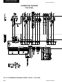
fig. 28 – elementary diagram, control circuit – ycal0064e_ - ycal0080e_....................172
fig. 29 – elementary diagram, POWER CIRCUIT – ycal0064e_ - ycal0080e_........................174
fig. 30 – connection diagram, middle market – ycal0064e_ - ycal0080e_.......................176
fig. 31 – ELEMENTARY diagram, middle market – ycal0064e_ - ycal0080e_.......................178
fig. 32 – elementary diagram, middle market – ycal0090E_ - ycal0094e_.......................179
fig. 33 – elementary diagram, control circuit – ycal0090E_ - ycal0094e_....................180
fig. 34 – elementary diagram, power circuit – ycal0090E_ - ycal0094e_........................182
fig. 35 – connection diagram, middle market high performance –
ycal0090E_ - ycal0094e_......................................................................................................184
fig. 36 – elementary diagram, control circuit – ycal0104e_.............................................186
fig. 37 – elementary diagram, power circuit – ycal0104e_.................................................188
fig. 38 – connection diagram, middle market high performance – ycal0104e_.........190
fig. 39 – elementary diagram, middle market high performance– ycal0104e_..........192
JOHNSON CONTROLS
13
FORM 150.62-NM8 (410)
LIST OF FIGURES (CONT'D)
fig. 40 – elementary diagram, middle market high performance –
ycal0114E_ - ycal0134e_.......................................................................................................193
fig. 41 – elementary diagram, control circuit – ycal0114E_ - YCAL0134E_....................194
fig. 42 – elementary diagram, power circuit – ycal0114E_ - YCAL0134E_........................196
fig. 43 – connection diagram, middle market high performance –
ycal0114E_ - YCAL0134E_.......................................................................................................198
FIG. 44 – TYPE CP 1...................................................................................................................................207
FIG. 45 – TYPE CP 2...................................................................................................................................207
FIG. 46 – R SPRING SEISMIC ISOLATOR.................................................................................................208
FIG. 47 – TYPE CP MOUNTING.................................................................................................................209
FIG. 48 – AEQM SPRING-FLEX MOUNTING.............................................................................................210
14
JOHNSON CONTROLS
FORM 150.62-NM8 (410)
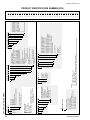
PRODUCT IDENTIFICATION NUMBER (PIN)
Basic MODEL Number
YCAL0080EC46XCA
1 2 3 4
Base product type
y
c
a
U
5 6 7 8
nominal capacity
0
: YORK
1
: Chiller
: Air-Cooled
: Condensing
Unit
L : Scroll
JOHNSON CONTROLS
9
unit designator
# # #
E : High Efficiency
# # #
Even Number:
60 HZ Nominal Tons
Odd Number:
50 HZ Nominal kW
10
refrigerant
c : R-22
B : R-407C
11 12 13
14 15
voltage/starter
design/development level
1
2
4
4
5
5
7
8
0
6
0
8
: 200 / 3/ 60 C
: 230 / 3 / 60
: 380 / 3 / 60
: 460 / 3 / 60
: 380-415 / 3 / 50
: 575 / 3 / 60
X : Across the Line
: Design Series
: Engineering a
Change
or PIN Level
15
16
X
X
X
D
X
T
: Control Transformer (factory)
C : Power Factor Capacitor
: SP Supply TB
: MP Supply TB
: SP Supply TB
: SP NF Disconnect Switch
: SP Circuit Breaker w/ Lockable Handle
3
D
S
A
R
: Aluminum
: Copper
: Black Fin
: Phenolic
X : TEAO Fan Motors
:
S :
X
1
2
3
4
5
6
7
8
B
CABINET FIELD
L
#
C
S
B
E
1
X
X
X
1 : 1" Deflection
S : Seismic
N : Neoprene Pads
: Low Sound Fans
: Wire Condenser Headers Only (factory)
: Wire (Full Unit) Enc. Panels (factory)
: Wire (Full Unit) Enc. Panels (field)
: Wire/Louvered Enc. Panels (factory)
: Wire/Louvered Enc. Panels (field)
: Louvered
(Cond. Only) Enc. Panels (factory)
: Louvered
(Cond. Only) Enc. Panels (field)
: Louvered
(Full Unit) Enc. Panels (factory)
: Louvered (Full Unit) Enc. Panels (field)
: Acoustic Sound Blanket
48 49 50 51 52 53 54
R
:
:
#
Low Ambient Kit (factory)
High Ambient Kit (factory)
Both Low / High Ambient (factory)
BAS/EMS Temp. Reset / Offset
Spanish LCD & Keypad Display
French LCD & Keypad Display
German LCD & Keypad Display
Discharge Pressure Transducers/
Readout Kit
Suction Pressure Transducers /
Readout Kit
Both Discharge & Suction Pressure Transducers / Readout
N. American Safety Code
(cU.L./cE.T.L.)
No Listing (typically 50 HZ non-CE,
non-U.L.
Remote Control Panel
Sequence Control & Automatic
Lead Transfer
NOTES:
1. Q :DENOTES SPECIAL / S.Q.
2. # :DENOTES STANDARD
3. X :w/in OPTIONS FIELD, DENOTES NO OPTION SELECTED
4. Agency Files (i.e. U.L. / E.T.L.; CE; ARI; ETC.) will contain info. based on the first 14 characters only.
X
C
B
P
L
N
C
:
:
:
:
:
:
:
:
:
:
: Leaving Supply Temp.
: Chicago Code Kit Req’d.
: Service Isolation Valves
: Both Chicago & Svc. Iso.
: Elec. Expansion Valve
: Hot Gas By-Pass req’d.
(1 circuit)
:X
: X
: X
X
: Crankcase Heater Std.
COMPRESSOR / PIPING FIELD
29 30 31 32 33 34 35 36 37
X
X
X
X
X
X
X
X
L
X
X
X
X
X
X
X
X
X
X
X
X
X
X
X
X
X
A
X
X
X
X
X
X
X
X
X
X
X
X
X
S
D
T
C
A
T
S
R
L
X
P
R
S
2
5
C
X
1
X
X
X
X
3
D
W
S
A
R
X
B
X
X
4
B
X
X
L
X
S
D
X : 1st Year Parts Only
B : 1st Year Parts & Labor
C : 2nd Year Parts Only
D : 2nd Year Parts & Labor
E : 5 Year Compressor Parts Only
F : 5 Year Compressor Parts & Labor Only
G : 5 Year Units Parts Only
H : 5 Year Unit Parts & Labor
55
EXTENDED FIELD
W
V
: 300 PSIG DWP Waterside
: Double Thick Insulation
: Weld Flange Kit
: Victaulic Flange Kit
: Flow Switch
: ASME Pressure Vessel &
Associated Codes
: Remote DX Cooler
R
S
B
45 46 47
S
F
G
I
CONDENSER FIELD
T
38 39 40 41 42 43 44
L
H
A
CONTROLS FIELD
20 21 22 23 24 25 26 27 28
EVAP. FIELD
MP = Multiple Point
SP = Single-Point
NF = Non-Fused
TB = Terminal Block
Ser. = Service
Ind. Sys. Brkr. & L. Ext. Handles = Individual System Breaker & Lockable External Handle
X
X
S
S
B
POWER FIELD
16 17 18 19
OPTIONS MODEL NUMBER
FORM 150.62-NM8 (410)
PRODUCT IDENTIFICATION NUMBER (PIN)
EXAMPLES:
16 17 18 19 20 21 22 23 24 25 26 27 28 29 30 31 32 33 34 35 36 37 38 39 40 41 42 43 44 45 46 47 48 49 50 51 52 53 54 55
JOHNSON CONTROLS
FORM 150.62-NM8 (410)
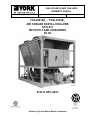
REFRIGERANT FLOW DIAGRAM
AIR COOLED CONDENSERS
YCAL REFRIGERANT FLOW DIAGRAM
(INCLUDING TEMPERATURE SENSORS & PRESSURE TRANSDUCERS)
NOTE: YCAL0040-0134 HAVE TWO REFRIGERANT
SYSTEMS AND ONE DX COOLER.
* HOT GAS OPTION - SYSTEM 1 ONLY
SIGHT GLASS /
MOISTURE INDICATOR
LIQUID LINE FILTER / DRIER
LIQUID LINE
SERVICE VALVE
LIQUID LINE
SOLENOID VALVE
HOT DISCHARGE
GAS LINE
OPTIONAL
DISCHARGE LINE
BALL VALVE
* SOLENOID OPERATED
HOT GAS BY PASS VALVE
OPTIONAL DISCHARGE
PRESSURE TRANSDUCER
OPTIONAL
SERVICE VALVE
HIGH PRESSURE
CUTOUT SWITCH
TXV
OPTIONAL
EQUALIZER
LINE
OPTIONAL
SUCTION LINE
BALL VALVE
OPTIONAL
RELIEF VALVE
300 PSIG
(20.68 BARG)
OPTIONAL
SERVICE
VALVE
DX COOLER
LOW PRESSURE SWITCH OR
SUCTION PRESSURE TRANSDUCER
RETURN WATER
TEMP. SENSOR
LEAVING CHILLED WATER
LEAVING
CHILLED WATER
TEMP. SENSOR
ENTERING CHILLED WATER
OIL EQUALIZING
LINE
2 OR 3 COMPRESSORS PER SYSTEM
LD07613A
Fig. 1 – REFRIGERANT FLOW DIAGRAM
JOHNSON CONTROLS
17
FORM 150.62-NM8 (410)
THIS PAGE INTENTIONALLY LEFT BLANK
18
JOHNSON CONTROLS
FORM 150.62-NM8 (410)
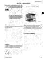
SECTION 1 - INSTALLATION
To ensure warranty coverage, this
equipment must be commissioned
and serviced by an authorized Johnson Controls service mechanic or a
qualified service person experienced in
chiller installation. Installation must
comply with all applicable codes, particularly in regard to electrical wiring
and other safety elements such as relief valves, HP cutout settings, design
working pressures, and ventilation requirements consistent with the amount
and type of refrigerant charge.
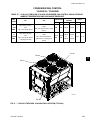
EXAMPLE OF PROPER LIFITING
1
Lethal voltages exist within the control
panels. Before servicing, open and tag
all disconnect switches.
29224(RIG)A
INSPECTION
INSTALLATION CHECK LIST
The following items,must be checked before placing
the units in operation.
1. Inspect the unit for shipping damage.
2. Rig unit using spreader bars.
3. Open the unit only to install water piping system.
Do not remove protective covers from water
connections until piping is ready for attachment.
Check water piping to ensure cleanliness.
4. Pipe unit using good piping practice (see ASHRAE
handbook section 215 and 195).
5. Check to see that the unit is installed and operated
within limitations (Refer to Operational and Voltage
Limitations located in Section 1 of this IOM).
The following pages outline detailed procedures to be
followed to install and startup the chiller.
Immediately upon receiving the unit, it should be
inspected for possible damage which may have
occurred during transit. If damage is evident, it should
be noted in the carrier’s freight bill. A written request
for inspection by the carrier’s agent should be made at
once. See Instruction manual, Form 50.15-NM for more
information and details.
LOCATION AND CLEARANCES
These units are designed for outdoor installations on
ground level, rooftop, or beside a building. Location
should be selected for minimum sun exposure and to
insure adequate supply of fresh air for the condenser.
The units must be installed with sufficient clearances
for air entrance to the condenser coil, for air discharge
away from the condenser, and for servicing access.
In installations where winter operation is intended and
snow accumulations are expected, additional height
must be provided to ensure normal condenser air flow.
HANDLING
These units are shipped as completely assembled units
containing full operating charge, and care should be
taken to avoid damage due to rough handling.
Clearances are listed under Dimensions in Section 1
of this IOM.
The unit should be lifted by inserting
hooks through the holes provided in
unit base rails. Spreader bars should be
used to avoid crushing the unit frame
rails with the lifting chains.
JOHNSON CONTROLS
19
INSTALLATION
FORM 150.62-NM8 (410)
Foundation
SPRING ISOLATORS (OPTIONAL)
The unit should be mounted on a flat and level
foundation, floor, or rooftop capable of supporting the
entire operating weight of the equipment. See Physical
Data in Section 1 of this IOM for operating weight.
If the unit is elevated beyond the normal reach of
service personnel, a suitable catwalk must be capable
of supporting service personnel, their equipment, and
the compressors.
When ordered, four (4) isolators will be furnished.
Ground Level Locations
It is important that the units be installed on a substantial
base that will not settle. A one piece concrete slab
with footers extended below the frost line is highly
recommended. Additionally, the slab should not be tied
to the main building foundations as noise and vibration
may be transmitted. Mounting holes are provided in the
steel channel for bolting the unit to its foundation. (See
Dimensions in Section 1 of this IOM.)
For ground level installations, precautions should be
taken to protect the unit from tampering by or injury to
unauthorized persons. Screws and/or latches on access
panels will prevent casual tampering. However, further
safety precautions such as a fenced-in enclosure or
locking devices on the panels may be advisable.
Identify the isolator, locate at the proper mounting point,
and adjust per instructions. See Isolator Data In Section
7 of this IOM.
COMPRESSOR MOUNTING
The compressors are mounted on four (4) rubber
isolators. The mounting bolts should not be loosened
or adjusted at installation of the chiller.
REMOTE COOLER OPTION
For units using remote cooler option, refer to instructions
included with miscellaneous cooler parts kit.
The unit and remote cooler are shipped with a 6 lb. (2.7
kg) nitrogen holding charge. The nitrogen charge must
be removed, and system evacuated, and the refrigerant
charge must be weighed-in according to the operating
charge listed in Table 15 “Physical Data”. Additional
charge must also be added for the refrigerant lines.
CHILLED WATER PIPING
Rooftop Locations
General
Choose a spot with adequate structural strength to
safely support the entire weight of the unit and service
personnel. Care must be taken not to damage the roof.
When the unit has been located in its final position, the
unit water piping may be connected. Normal installation
precautions should be observed in order to receive
maximum operating efficiencies. Piping should be kept
free of all foreign matter. All chilled water evaporator
piping must comply in all respects with local plumbing
codes and ordinances.
Consult the building contractor or architect if the roof
is bonded. Roof installations should have wooden
beams (treated to reduce deterioration), cork, rubber,
or vibration isolators under the base to minimize
vibration.
Noise Sensitive Locations
Efforts should be made to assure that the chiller is not
located next to occupied spaces or noise sensitive areas
where chiller noise level would be a problem. Chiller
noise is a result of compressor and fan operation.
Considerations should be made utilizing noise levels
published in the YORK Engineering Guide for
the specific chiller model. Sound blankets for the
compressors and low sound fans are available.
20
Since elbows, tees and valves decrease pump capacity,
all piping should be kept as straight and as simple as
possible.
All piping must be supported independent of the chiller.
Consideration should be given to compressor access when laying out water
piping. Routing the water piping too
close to the unit could make compressor servicing/replacement difficult.
JOHNSON CONTROLS
FORM 150.62-NM8 (410)
Hand stop valves should be installed in all lines to
facilitate servicing.
Piping to the inlet and outlet connections of the chiller
should include high-pressure rubber hose or piping
loops to ensure against transmission of water pump
vibration. The necessary components must be obtained
in the field.
Drain connections should be provided at all low points
to permit complete drainage of the cooler and system
water piping.
A small valve or valves should be installed at the highest
point or points in the chilled water piping to allow any
trapped air to be purged. Vent and drain connections
should be extended beyond the insulation to make them
accessible.
6. The chilled water lines that are exposed to outdoor
ambients should be wrapped with supplemental
heater cable and insulated to protect against freezeup during low ambient periods, and to prevent
formation of condensation on lines in warm humid
locations.
7. A chilled water flow switch, (either by YORK or
others) must be installed in the leaving water piping
of the cooler. There should be a straight horizontal
run of at least 5 diameters on each side of the switch.
Adjust the flow switch paddle to the size of the pipe
in which it is to be installed. (See manufacturer’s
instructions furnished with the switch.) The switch is
to be wired to terminals 13 and 14 of CTB1 located
in the control panel, as shown on the unit wiring
diagram.
The flow switch MUST NOT be used to
start and stop the chiller (i.e. starting
and stopping the chilled water pump).
It is intended only as a safety switch.
The piping to and from the cooler must be designed to
suit the individual installation. It is important that the
following considerations be observed:
1. The chilled liquid piping system should be laid out
so that the circulating pump discharges directly
into the cooler. The suction for this pump should
be taken from the piping system return line and not
the cooler. This piping scheme is recommended,
but is not mandatory.
2. The inlet and outlet cooler connection sizes are
3" (YCAL0014 through 0024), 4" (YCAL0030
through 0034), 6" (YCAL0040 through 0080), or
8" (YCAL0090 through 0134).
3. A strainer, preferably 40 mesh, must be installed
in the cooler inlet line just ahead of the cooler. This
is important to protect the cooler from entrance of
large particles which could cause damage to the
evaporator.
4. All chilled liquid piping should be thoroughly
flushed to free it from foreign material before the
system is placed into operation. Use care not to flush
any foreign material into or through the cooler.
5. As an aid to servicing, thermometers and pressure
gauges should be installed in the inlet and outlet
water lines.
JOHNSON CONTROLS
WIRING
Liquid Chillers are shipped with all factory-mounted
controls wired for operation.
Field Wiring
Power wiring must be provided through a fused
disconnect switch to the unit terminals (or optional
molded disconnect switch) in accordance with N.E.C.
or local code requirements. Minimum circuit ampacity
and maximum dual element fuse size are given in the
Tables 2 – 6.
A 120-1-60, 15 amp source must be supplied for the
control panel through a fused disconnect when a control
panel transformer (optional) is not provided. Refer to
Table 1 and Fig. 2 through Fig. 6.
See Fig. 2 through Fig. 6 and unit wiring diagrams
for field and power wiring connections, chilled water
pump starter contacts, alarm contacts, compressor run
status contacts, PWM input, and load limit input. Refer
to Unit Operation in Section 2 of this IOM for a detailed
description of operation concerning aforementioned
contacts and inputs.
21
1
INSTALLATION
FORM 150.62-NM8 (410)
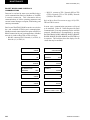
Evaporator Pump Start Contacts
Remote Emergency Cutoff
Terminal block CTB2 – terminals 23 to 24, are normallyopen contacts that can be used to switch field supplied
power to provide a start signal to the evaporator pump
contactor. The contacts will be closed when any of the
following conditions occur:
Immediate shutdown of the chiller can be accomplished
by opening a field-installed dry contact to break the elec
trical circuit between terminals 5 to L on terminal block
TB1. The unit is shipped with a factory jumper installed
between terminals 5 to L, which must be removed if
emergency shutdown contacts are installed. Refer to
Fig. 6 and unit wiring diagram.
1. Low Leaving Chilled Liquid fault
2. Any compressor is running
3. Daily schedule is not programmed OFF and the Unit Switch is ON
The pump will not run if the micro panel has been
powered up for less than 30 seconds, or if the pump
has run in the last 30 seconds, to prevent pump motor
overheating. Refer to Fig. 6 and unit wiring diagram.
System Run Contacts
Contacts are available to monitor system status.
Normally‑open auxiliary contacts from each compressor
contactor are wired in parallel with TB1 – terminals 25
to 26 for system 1, and TB1 – terminals 27 to 28 for
system 2 (YCAL0040 ‑ YCAL0134). Refer to Fig. 6
and unit wiring diagram.
Alarm Status Contacts
Normally‑open contacts are available for each re
frigerant system. These normally‑open contacts close
when the system is functioning normally. The respective
contacts will open when the unit is shut down on a unit
fault, or locked out on a system fault. Field connections
are at TB1 terminals 29 to 30 (system 1), and terminals
31 to 32 (system 2 YCAL0040 ‑ YCAL0134).
Remote Start/Stop Contacts
To remotely start and stop the chiller, dry contacts can be
wired in series with the flow switch and CTB1 ‑ termi
nals 13 to 14. Refer to Fig. 6 and unit wiring diagram.
22
PWM Input
The PWM input allows reset of the chilled liquid set
point by supplying a “timed” contact closure. Field
wiring should be connected to TB1 – terminals 13 to 20.
A detailed explanation is provided in Section 2, “Unit
Controls”. Refer to Fig. 6 and unit wiring diagram.
Load Limit Input
Load limiting is a feature that prevents the unit from
loading beyond a desired value. The unit can be “load
limited” either 33%, 40%, 50%, 66% or 80%, depending
on the number of compressors on unit. The field
connections are wired to TB1 – terminals 13 to 21, and
work in conjunction with the PWM inputs. A detailed
explanation is provided in Section 2, “Unit Controls”.
Refer to Fig. 6 and unit wiring diagram.
When using the Load Limit feature,
the PWM feature will not function. Simultaneous operation of load limiting
and temperature reset (PWM input)
cannot be done.
Flow Switch Input
The flow switch is field wired to CTB1 terminals 13 and
14. See Fig. 6 and unit wiring diagram.
Compressor Heaters
Compressor heaters are standard. If power is OFF more
than two hours, the crankcase heaters must be energized
for 18 - 24 hours prior to restarting a compressor. This
will assure that liquid slugging and oil dilution does not
damage the compressors on start.
JOHNSON CONTROLS
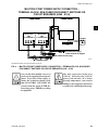
FORM 150.62-NM8 (410)
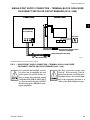
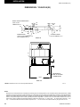
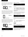
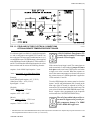
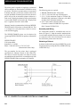
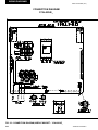
single-point supply connection – terminal block, non-fused
disconnect switch or circuit breaker (0014 - 0080)
Power Panel
Control Panel
2
L
Terminal Block,
NF Disconnect SW
or Circuit Breaker
1
MICROPANEL
CTB2
Flow Switch
GRD
1L1 1L2 1L3
13
14
CTB1
Field Provided 120-1-60
Micropanel Power Supply if Control
Transformer not Supplied
Field Provided Unit Power Supply
LD07719
See electrical note 9
See Electrical Notes and Legend located on page 28.
Fig. 2 – single-point supply connection – terminal block, non-fused
disconnect switch or circuit breaker (0014 - 0080)
It is possible that multiple sources
of power can be supplying the unit
power panel. To prevent serious injury or death, the technician should
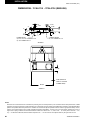
verify that NO LETHAL VOLTAGES
are present inside the panel AFTER
disconnecting power, PRIOR to working on equipment.
JOHNSON CONTROLS
The unit evaporator heater uses
120VAC. Disconnecting 120VAC
power from the unit, at or below freezing temperatures, can result in damage to the evaporator and unit as a
result of the chilled liquid freezing.
23
INSTALLATION
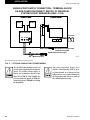
FORM 150.62-NM8 (410)
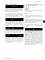
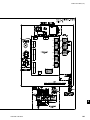
multiple point power supply connection –
terminal block (0040 - 0080)
Power Panel
Control Panel
2
L
MICROPANEL
Terminal
Block1
Terminal
Block2
CTB2
1L1 1L2 1L3
Flow Switch
GRD
GRD
2L1 2L2 2L3
13
14
CTB1
Field Provided 120-1-60
Micropanel Power Supply if Control
Transformer not Supplied
Field Provided Unit Power Supply
LD07720
See electrical note 9
* Models YCAL0040 through 0080 only (Models YCAL0014 through 0034 are Single Point)
See Electrical Notes and Legend located on page 28.
Fig. 3 – multiple point power supply connection – terminal block (0040 - 0080)
It is possible that multiple sources of
power can be supplying the unit power
panel. To prevent serious injury or
death, the technician should verify
that NO LETHAL VOLTAGES are
present inside the panel AFTER disconnecting power, PRIOR to working
on equipment.
24
The unit evaporator heater uses
120VAC. Disconnecting 120VAC power from the unit, at or below freezing
temperatures, can result in damage to
the evaporator and unit as a result of
the chilled liquid freezing.
JOHNSON CONTROLS
FORM 150.62-NM8 (410)
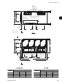
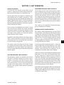
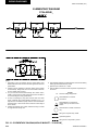
multiple point power supply connection –
terminal block, non-fused disconnect switches or
circuit breakers (0090 - 0134)
Power Panel
Control Panel
2
L
1
MICROPANEL
Terminal Block1,
NF Disconnect
SW1
or Circuit Breaker1
1L1 1L2 1L3
Terminal Block2,
NF Disconnect
SW2
or Circuit Breaker2
CTB2
Flow Switch
GRD
GRD
2L1 2L2 2L3
13
14
CTB1
Field Provided 120-1-60
Micropanel Power Supply if
Control Transformer not Supplied
Field Provided Unit Power Supply
See electrical note 9
LD07721
See Electrical Notes and Legend located on page 28.
Fig. 4 – multiple point power supply connection – terminal block, non-fused
disconnect switches or circuit breakers (0090 - 0134)
It is possible that multiple sources of
power can be supplying the unit power
panel. To prevent serious injury or
death, the technician should verify
that NO LETHAL VOLTAGES are
present inside the panel AFTER disconnecting power, PRIOR to working
on equipment.
JOHNSON CONTROLS
The unit evaporator heater uses
120VAC. Disconnecting 120VAC
power from the unit, at or below
freezing temperatures, can result in
damage to the evaporator and unit as
a result of the chilled liquid freezing.
25
INSTALLATION
FORM 150.62-NM8 (410)
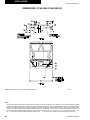
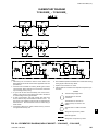
single-point SUPPLY connection – terminal block
or non-fused disconnect switch to individual
system circuit breakers (0090 - 0134)
Power Panel
Circuit
Breaker1
Control Panel
Circuit
Breaker2
2
L
MICROPANEL
Terminal Block or
NF Disconnect SW
CTB2
Flow Switch
GRD
1L1 1L2 1L3
13
14
CTB1
Field Provided 120-1-60
Micropanel Power Supply if Control
Transformer not Supplied
Field Provided Unit Power Supply
See electrical note 9
LD07722
See Electrical Notes and Legend located on page 28.
Fig. 5 – optional single-point power wiring
It is possible that multiple sources of
power can be supplying the unit power
panel. To prevent serious injury or
death, the technician should verify
that NO LETHAL VOLTAGES are
present inside the panel AFTER disconnecting power, PRIOR to working
on equipment.
26
The unit evaporator heater uses
120VAC. Disconnecting 120VAC power from the unit, at or below freezing
temperatures, can result in damage to
the evaporator and unit as a result of
the chilled liquid freezing.
JOHNSON CONTROLS
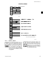
FORM 150.62-NM8 (410)
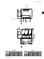
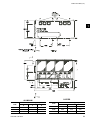
control WIRING
FLOW SW
REMOTE START/STOP
13
14
PWM INPUT
13
20
13
LOAD LIMIT INPUT
1
21
CTB1
LD07725
*
* Factory wired with optional transformer.
LD07730A
Fig. 6 – control wiring
It is possible that multiple sources of
power can be supplying the unit power
panel. To prevent serious injury or
death, the technician should verify
that NO LETHAL VOLTAGES are
present inside the panel AFTER disconnecting power, PRIOR to working
on equipment.
JOHNSON CONTROLS
The unit evaporator heater uses
120VAC. Disconnecting 120VAC power from the unit, at or below freezing
temperatures, can result in damage to
the evaporator and unit as a result of
the chilled liquid freezing.
27
INSTALLATION
FORM 150.62-NM8 (410)
ELECTRICAL NOTES and legend
1. Minimum Circuit Ampacity (MCA) is based on
125% of the rated load amps for the largest motor
plus 100% of the rated load amps for all other loads
included in the circuit, per N.E.C. Article 430.33.
If the Factory-mounted Control Transformer is
provided, add the following to the system MCA
values in the electrical tables for the system
supplying power to the optional transformer. -17,
add 2.5 amps; -28, add 2.3 amps; -40, add 1.5 amps,
-46, add 1.3 amps; -58, add 1 amp.
2. The minimum recommended disconnect switch is
based on 115% of the rated load amps for all loads
included in the circuit, per N.E.C. Article 440.12
(A) 1.
3. Minimum fuse size is based upon 150% of the rated
load amps for the largest motor plus 100% of the
rated load amps for all other loads included in the
circuit to avoid nuisance trips at startup due to lock
rotor amps. It is not recommended in applications
where brown outs, frequent starting and stopping of
the unit, and/or operation at ambient temperatures
in excess of 95°F is anticipated.
4. Maximum fuse size is based upon 225% of the rated
load amps for the largest motor plus 100% of the
rated load amps for all other loads included in the
circuit, per N.E.C. Article 440.22.
5. Circuit breakers must be U.L. listed and CSA
certified and maximum size is based on 225% of the
rated load amps for the largest motor plus 100% of
the rated load amps for all other loads included in
the circuit. Exception: YCAL0014 and YCAL0020
must have the optional factory overloads installed
to use a standard circuit breaker. Otherwise, HACRtype circuit breakers must be used. Maximum
HACR circuit breaker rating is based on 225% of
the rated load amps for the largest motor plus 100%
of the rated load amps for all other loads included
in the circuit.
6. The “Incoming Wire Range” is the minimum and
maximum wire size that can be accommodated by
the unit wiring lugs. The (2) preceding the wire
range indicates the number of termination points
available per phase of the wire range specified.
Actual wire size and number of wires per phase
must be determined based on the National Electrical
Code, using copper connectors only. Field wiring
must also comply with local codes.
7. A ground lug is provided for each compressor system
to accommodate a field grounding conductor per
N.E.C. Table 250.122. A control circuit grounding
lug is also supplied.
8. The supplied disconnect is a “Disconnecting Means”
as defined in the N.E.C. 100.I, and is intended for
isolating the unit for the available power supply
to perform maintenance and troubleshooting. This
disconnect is not intended to be a Load Break
Device.
9. Field wiring by others which complies to the
National Electrical Code and local codes.
LEGEND
ACR-LINE
ACROSS -THE-LINE START
C.B.
CIRCUIT BREAKER
D.E.
DUAL ELEMENT FUSE
DISC SW
DISCONNECT SWITCH
FACT MOUNT CB
FACTORY-MOUNTED CIRCUIT BREAKER
-40 = 380-3-60
FLA
FULL LOAD AMPS
-46 = 460-3-60
HZ
HERTZ
-58 = 575-3-60
MAX
MAXIMUM
VOLTAGE CODE
-17 = 200-3-60
-28 = 230-3-60
MCA
MINIMUM CIRCUIT AMPACITY
MIN
MINIMUM
LEGEND:
MIN NF
MINIMUM NON FUSED
RLA
RATED LOAD AMPS
S.P. WIRE
SINGLE-POINT WIRING
Field Wiring
Factory Wiring
UNIT MTD SERV SW
UNIT MOUNTED SERVICE (NON-FUSED
DISCONNECT SWITCH)
LRA
LOCKED ROTOR AMPS
28
JOHNSON CONTROLS
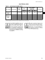
FORM 150.62-NM8 (410)
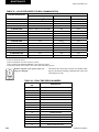
ELECTRICAL DATA
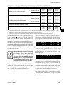
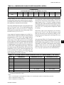
table 1 – MICRO PANEL POWER SUPPLY
UNIT VOLTAGE
UNIT VOLTAGE
MODELS w/o
CONTROL
TRANS
MODELS w/
CONTROL
TRANS
CONTROL
POWER
115-1-60/50
MCA
OVER CURRENT
PROTECTION,
SEE NOTE B
NF DISC SW
NOTE A
MIN
MAX
15A
10A
15A
30 A / 240V
-17
200-1-60
15A
10A
15A
30 A / 240V
-28
230-1-60
15A
10A
15A
30 A / 240V
-40
380-1-60
15A
10A
15A
30 A / 480V
-46
460-1-60
15A
10A
15A
30 A / 480V
-58
575-1-60
15A
10A
15A
30 A / 600V
A. Minimum #14 AWG, 75°C, Copper Recommended
B. Minimum and Maximum Over Current Protection, Dual Element Fuse or Circuit Breaker
It is possible that multiple sources of
power can be supplying the unit power
panel. To prevent serious injury or
death, the technician should verify
that NO LETHAL VOLTAGES are
present inside the panel AFTER disconnecting power, PRIOR to working
on equipment.
JOHNSON CONTROLS
The unit evaporator heater uses
120VAC. Disconnecting 120VAC power from the unit, at or below freezing
temperatures, can result in damage to
the evaporator and unit as a result of
the chilled liquid freezing.
29
1
INSTALLATION
FORM 150.62-NM8 (410)
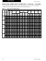
Single-Point Power Supply Connections – YCAL0014E_ - YCAL0034E_
One Field Provided Power Supply to the chiller. Field connections to Factory Provided Power Terminal Block
(standard), Non-Fused Disconnect Switch (optional) or Circuit Breaker (optional).
table 2 – SINGLE-POINT POWER supply
MODEL
VOLT HZ
MCA1
YCAL
0014
0020
0024
0030
0034
200
230
380
460
575
200
230
380
460
575
200
230
380
460
575
200
230
380
460
575
200
230
380
460
575
60
60
60
60
60
60
60
60
60
60
60
60
60
60
60
60
60
60
60
60
60
60
60
60
60
81
75
44
37
29
101
94
54
46
36
128
119
69
58
46
138
128
74
62
49
178
165
96
79
63
MIN
N/F
DISC
SW2
100
100
60
60
60
150
100
60
60
60
150
150
100
60
60
150
150
100
100
60
200
200
150
100
100
SINGLE POINT FIELD SUPPLIED WIRING
INCOMING (LUGS) WIRE
RANGE6
D.E. FUSE CKT. BKR.5
TERNF DISC. CIRCUIT
MINAL
SWITCH BREAKMIN3 MAX4 MIN MAX BLOCK
(opt) ER (opt)
(std)
90
100
90 100 # 10 - # 1 # 14 - 1/0 # 14 - 1/0
90
100
90 100 # 10 - # 1 # 14 - 1/0 # 14 - 1/0
50
50
50
50 # 10 - # 1 # 14 - 1/0 # 14 - 2
40
45
40
45 # 10 - # 1 # 14 - 1/0 # 14 - 2
35
35
35
35 # 10 - # 1 # 14 - 1/0 # 14 - 2
110
125 110 125 # 10 - # 1 # 14 - 1/0 # 2 - 4/0
110
125 110 125 # 10 - # 1 # 14 - 1/0 # 2 - 4/0
60
70
60
70 # 10 - # 1 # 14 - 1/0 # 14 - 2
50
60
50
60 # 10 - # 1 # 14 - 1/0 # 14 - 2
40
45
40
45 # 10 - # 1 # 14 - 1/0 # 14 - 2
150
175 150 175 # 10 - 3/0 # 2 - 4/0 # 2 - 4/0
150
150 150 150 # 10 - 3/0 # 2 - 4/0 # 2 - 4/0
80
90
80
90 # 10 - # 1 # 14 - 1/0 # 14 - 1/0
70
70
70
70 # 10 - # 1 # 14 - 1/0 # 14 - 1/0
50
60
50
60 # 10 - # 1 # 14 - 1/0 # 14 - 2
175
175 175 175 # 10 - 3/0 # 2 - 4/0 # 3 - 300
150
175 150 175 # 10 - 3/0 # 2 - 4/0 # 3 - 300
90
100
90 100 # 10 - # 1 # 14 - 1/0 # 14 - 1/0
70
80
70
80 # 10 - # 1 # 14 - 1/0 # 14 - 1/0
60
60
60
60 # 10 - # 1 # 14 - 1/0 # 14 - 2
200
225 200 225 # 10 - 300 # 3 - 300 # 3 - 300
200
200 200 200 # 10 - 300 # 3 - 300 # 3 - 300
110 110 110 # 10 - # 1 # 14 - 1/0 # 2 - 4/0
110
90
100
90 100 # 10 - # 1 # 14 - 1/0 # 14 - 1/0
70
70
70
70 # 10 - # 1 # 14 - 1/0 # 14 - 1/0
SYSTEM #1 COMPRESSOR & FAN
COMPR. #1 COMPR. #2 COMPR. #3
FANS
RLA LRA RLA
LRA RLA LRA QTY
FLA
(EA)
28.3
26.2
15.1
12.5
10.0
37.4
34.6
19.9
16.5
13.2
49.4
45.8
26.4
21.8
17.4
53.8
49.8
28.7
23.7
19.0
49.4
45.8
26.4
21.8
17.4
189
189
112
99
74
278
278
151
127
100
350
350
195
158
125
425
425
239
187
148
350
350
195
158
125
7.6
7.4
4.5
4.0
2.9
7.6
7.4
4.5
4.0
2.9
7.6
7.4
4.5
4.0
2.9
7.6
7.4
4.5
4.0
2.9
7.6
7.4
4.5
4.0
2.9
189
189
112
99
74
278
278
151
127
100
350
350
195
158
125
425
425
239
187
148
350
350
195
158
125
28.3
26.2
15.1
12.5
10.0
37.4
34.6
19.9
16.5
13.2
49.4
45.8
26.4
21.8
17.4
53.8
49.8
28.7
23.7
19.0
49.4
45.8
26.4
21.8
17.4
—
—
—
—
—
—
—
—
—
—
—
—
—
—
—
—
—
—
—
—
49.4
45.8
26.4
21.8
17.4
—
—
—
—
—
—
—
—
—
—
—
—
—
—
—
—
—
——
—
350
350
195
158
125
2
2
2
2
2
2
2
2
2
2
2
2
2
2
2
2
2
2
2
2
2
2
2
2
2
See Notes and Legend on page 28
30
JOHNSON CONTROLS
FORM 150.62-NM8 (410)
THIS PAGE INTENTIONALLY LEFT BLANK
JOHNSON CONTROLS
31
INSTALLATION
FORM 150.62-NM8 (410)
Electrical Data – Dual Point Power Supply Connections –
YCAL0040E_ - YCAL0080E_
Two Field Provided Power Supply Circuits to the chiller. Field connections to Factory Provided Terminal Blocks
per system.
table 3 – DUAL POINT POWER supply connections
MODEL
VOLT
YCAL
0040
0042
0044
0050
0060
0064
0070
0074
0080
HZ
SYSTEM #1 FIELD SUPPLIED WIRING
SYSTEM #1 COMPRESSOR & FAN
INCOMING (LUGS) WIRE
MIN N/F D.E. FUSE
RANGE6
CKT. BKR.5
COMPR. #1 COMPR. #2 COMPR. #3
FANS
CIR
TERMINAL NF DISC.
MCA1 DISC
2
BLOCK
SWITCH
BREAKER
SW
MIN3 MAX4 MIN MAX
RLA LRA RLA LRA RLA LRA QTY FLA(EA)
(std)
(opt)
(opt)
101
150
110
125
110
125 # 10 - # 1 # 14 - 1/0 # 2 - 4/0 37.4 278 37.4 278
—
—
2
7.8
200
60
230
60
94
100
110
125
110
125
# 10 - # 1 # 14 - 1/0
# 2 - 4/0
34.6
278
34.6 278
—
—
2
7.8
380
60
55
60
60
70
60
70
# 10 - # 1 # 14 - 1/0
# 14 - 2
19.9
151
19.9 151
—
—
2
4.7
460
60
46
60
50
60
50
60
# 10 - # 1 # 14 - 1/0
# 14 - 2
16.5
127
16.5 127
—
—
2
4.0
575
60
36
60
40
45
40
45
# 10 - # 1 # 14 - 1/0
# 14 - 2
13.2
100
13.2 100
—
—
2
3.1
200
60
128
150
150
175
150
125
# 10 - 3/0 # 2 - 4/0
# 2 - 4/0
49.4
350
49.4 350
—
—
2
7.8
230
60
119
150
150
150
150
125
# 10 - 3/0 # 2 - 4/0
# 2 - 4/0
45.8
350
45.8 350
—
—
2
7.8
380
60
69
100
80
90
80
70
# 10 - # 1 # 14 - 1/0 # 14 - 1/0
26.4
195
26.4 195
—
—
2
4.7
460
60
58
60
70
70
70
60
# 10 - # 1 # 14 - 1/0 # 14 - 1/0
21.8
158
21.8 158
—
—
2
4.0
575
60
46
60
50
60
50
45
# 10 - # 1 # 14 - 1/0
# 14 - 2
17.4
125
17.4 125
—
—
2
3.1
200
60
128
150
150
175
150
175
# 10 - 3/0 # 2 - 4/0
# 2 - 4/0
49.4
350
49.4 350
—
—
2
7.8
230
60
119
150
150
150
150
150
# 10 - 3/0 # 2 - 4/0
# 2 - 4/0
45.8
350
45.8 350
—
—
2
7.8
380
60
69
100
80
90
80
90
# 10 - # 1 # 14 - 1/0 # 14 - 1/0
26.4
195
26.4 195
—
—
2
4.7
460
60
58
60
70
70
70
70
# 10 - # 1 # 14 - 1/0 # 14 - 1/0
21.8
158
21.8 158
—
—
2
4.0
575
60
46
60
50
60
50
60
# 10 - # 1 # 14 - 1/0
# 14 - 2
17.4
125
17.4 125
—
—
2
3.1
200
60
138
150
175
175
175
175
# 10 - 3/0 # 2 - 4/0
# 3 - 300
53.8
425
53.8 425
—
—
2
7.8
230
60
128
150
150
175
150
150
# 10 - 3/0 # 2 - 4/0
# 3 - 300
49.8
425
49.8 425
—
—
2
7.8
380
60
75
100
90
100
90
90
# 10 - # 1 # 14 - 1/0 # 14 - 1/0
28.7
239
28.7 239
—
—
2
4.7
460
60
62
100
70
80
70
70
# 10 - # 1 # 14 - 1/0 # 14 - 1/0
23.7
187
23.7 187
—
—
2
4.0
575
60
49
60
60
60
60
60
# 10 - # 1 # 14 - 1/0
# 14 - 2
19.0
148
19.0 148
—
—
2
3.1
200
60
138
150
175
175
175
175
# 10 - 3/0 # 2 - 4/0
# 3 - 300
53.8
425
53.8 425
—
—
2
7.8
230
60
128
150
150
175
150
175
# 10 - 3/0 # 2 - 4/0
# 3 - 300
49.8
425
49.8 425
—
—
2
7.8
380
60
75
100
90
100
90
100
# 10 - # 1 # 14 - 1/0 # 14 - 1/0
28.7
239
28.7 239
—
—
2
4.7
460
60
62
100
70
80
70
80
# 10 - # 1 # 14 - 1/0 # 14 - 1/0
23.7
187
23.7 187
—
—
2
4.0
575
60
49
60
60
60
60
60
# 10 - # 1 # 14 - 1/0
19.0
148
19.0 148
—-
—
2
3.1
# 14 - 2
200
60
178
200
200
225
200
225
# 10 - 300 # 3 - 300
# 3 - 300
49.4
350
49.4 350
49.4
350
2
7.8
230
60
165
200
200
200
200
200
# 10 - 300 # 3 - 300
# 3 - 300
45.8
350
45.8 350
45.8
350
2
7.8
380
60
96
150
110
110
110
110
# 10 - # 1 # 14 - 1/0 # 14 - 1/0
26.4
195
26.4 195
26.4
195
2
4.7
460
60
79
100
90
100
90
100
# 10 - # 1 # 14 - 1/0 # 14 - 1/0
21.8
158
21.8 158
21.8
158
2
4.0
575
60
63
100
70
80
70
80
# 10 - # 1 # 14 - 1/0 # 14 - 1/0
17.4
125
17.4 125
17.4
125
2
3.1
200
60
192
250
225
225
225
225
# 10 - 300 # 3 - 300
# 3 - 300
53.8
425
53.8 425
53.8
425
2
7.8
230
60
178
200
200
225
200
225
# 10 - 300 # 3 - 300
# 3 - 300
49.8
425
49.8 425
49.8
425
2
7.8
380
60
103
150
125
125
125
125
# 10 - # 1 # 2 - 4/0
# 2 - 4/0
28.7
239
28.7 239
28.7
239
2
4.7
460
60
86
100
100
100
100
100
# 10 - # 1 # 14 - 1/0 # 14 - 1/0
23.7
187
23.7 187
23.7
187
2
4.0
575
60
68
100
80
80
80
80
# 10 - # 1 # 14 - 1/0 # 14 - 1/0
19.0
148
19.0 148
19.0
148
2
3.1
See Notes and Legend on page 28.
32
JOHNSON CONTROLS
FORM 150.62-NM8 (410)
Electrical Data – Dual Point Power Supply Connections –
YCAL0040E_ - YCAL0080E_
SYSTEM #2 FIELD SUPPLIED WIRING
COMPR. COMPR. COMPR.
FANS
#1
#2
#3
MIN N/F
TERMINAL
NF
DISC.
CIR
BREAKER
MCA
DISC SW2 MIN3 MAX4 MIN MAX BLOCK (std) SWITCH (opt)
RLA LRA RLA LRA RLA LRA QTY FLA(EA)
(opt)
D.E. FUSE
1
CKT.
BKR.5
SYSTEM #2 COMPRESSOR & FAN
INCOMING (LUGS) WIRE RANGE6
101
150
110
125 110 125
94
100
110
125 110 125
# 10 - # 1
# 14 - 1/0
# 2 - 4/0
34.6 278 34.6 278
—
—
2
7.8
55
60
60
70
# 10 - # 1
# 14 - 1/0
# 14 - 2
19.9 151 19.9 151
—
—
2
4.7
60
70
# 10 - # 1
# 14 - 1/0
# 2 - 4/0
37.4 278 37.4 278
—
—
2
46
60
50
60
50
60
# 10 - # 1
# 14 - 1/0
# 14 - 2
16.5 127 16.5 127
—
—
2
4.0
36
60
40
45
40
45
# 10 - # 1
# 14 - 1/0
# 14 - 2
13.2 100 13.2 100
—
—
2
3.1
101
150
110
125 110 125
# 10 - # 1
# 14 - 1/0
# 2 - 4/0
37.4 278 37.4 278
—
—
2
7.8
94
100
110
125 110 125
# 10 - # 1
# 14 - 1/0
# 2 - 4/0
34.6 278 34.6 278
—
—
2
7.8
55
60
60
70
60
70
# 10 - # 1
# 14 - 1/0
# 14 - 1/0
19.9 151 19.9 151
—
—
2
4.7
46
60
50
60
50
60
# 10 - # 1
# 14 - 1/0
# 14 - 2
16.5 127 16.5 127
—
—
2
4.0
40
36
60
40
45
45
# 10 - # 1
# 14 - 1/0
# 14 - 2
13.2 100 13.2 100
—
—
2
3.1
128
150
150
175 150 175
# 10 - 3/0
# 2 - 4/0
# 2 - 4/0
49.4 350 49.4 350
—
—
2
7.8
119
150
150
150 150 150
# 10 - 3/0
# 2 - 4/0
# 2 - 4/0
45.8 350 45.8 350
—
—
2
7.8
69
100
80
90
80
90
# 10 - # 1
# 14 - 1/0
# 14 - 1/0
26.4 195 26.4 195
—
—
2
4.7
58
60
70
70
70
70
# 10 - # 1
# 14 - 1/0
# 14 - 1/0
21.8 158 21.8 158
—
—
2
4.0
50
46
60
50
60
60
# 10 - # 1
# 14 - 1/0
# 14 - 2
17.4 125 17.4 125
—
—
2
3.1
128
150
150
175 150 175
# 10 - 3/0
# 2 - 4/0
# 2 - 4/0
49.4 350 49.4 350
—
—
2
7.8
119
150
150
150 150 150
# 10 - 3/0
# 2 - 4/0
# 2 - 4/0
45.8 350 45.8 350
—
—
2
7.8
69
100
80
90
# 10 - # 1
# 14 - 1/0
# 14 - 1/0
26.4 195 26.4 195
—
—
2
4.7
80
90
58
60
70
70
70
70
# 10 - # 1
# 14 - 1/0
# 14 - 1/0
21.8 158 21.8 158
—
—
2
4.0
46
60
50
60
50
60
# 10 - # 1
# 14 - 1/0
# 14 - 2
17.4 125 17.4 125
—
—
2
3.1
138
150
175
175 175 175
# 10 - 3/0
# 2 - 4/0
# 3 - 300
53.8 425 53.8 425
—
—
2
7.8
128
150
150
175 150 175
# 10 - 3/0
# 2 - 4/0
# 3 - 300
49.8 425 49.8 425
—
—
2
7.8
75
100
90
100
90 100
# 10 - # 1
# 14 - 1/0
# 14 - 1/0
28.7 239 28.7 239
—
—
2
4.7
62
100
70
80
70
80
# 10 - # 1
# 14 - 1/0
# 14 - 1/0
23.7 187 23.7 187
—
—
2
4.0
60
—
49
60
60
60
60
# 10 - # 1
# 14 - 1/0
# 14 - 2
19.0 148 19.0 148
—
2
3.1
138
150
150
175 150 175
# 10 - 3/0
# 2 - 4/0
# 2 - 4/0
37.4 278 37.4 278 37.4 278
2
7.8
129
150
150
150 150 150
# 10 - 3/0
# 2 - 4/0
# 2 - 4/0
34.6 278 34.6 278 34.6 278
2
7.8
75
100
80
90
80
90
# 10 - # 1
# 14 - 1/0
# 14 - 1/0
19.9 151 19.9 151 19.9 151
2
4.7
62
100
70
70
70
70
# 10 - # 1
# 14 - 1/0
# 14 - 1/0
16.5 127 16.5 127 16.5 127
2
4.0
60
50
60
60
60
60
# 10 - # 1
# 14 - 1/0
# 14 - 1/0
13.2 100 13.2 100 13.2 100
2
3.1
178
200
200
225 200 225
# 10 - 300
# 3 - 300
# 3 - 300
49.4 350 49.4 350 49.4 350
2
7.8
165
200
200
200 200 200
# 10 - 300
# 3 - 300
# 3 - 300
45.8 350 45.8 350 45.8 350
2
7.8
96
150
110
110 110 110
# 10 - # 1
# 14 - 1/0
# 14 - 1/0
26.4 195 26.4 195 26.4 195
2
4.7
79
100
90
100
90 100
# 10 - # 1
# 14 - 1/0
# 14 - 1/0
21.8 158 21.8 158 21.8 158
2
4.0
70
63
100
70
80
80
# 10 - # 1
# 14 - 1/0
# 14 - 1/0
17.4 125 17.4 125 17.4 125
2
3.1
178
200
200
225 200 225
# 10 - 300
# 3 - 300
# 3 - 300
49.4 350 49.4 350 49.4 350
2
7.8
165
200
200
200 200 200
# 10 - 300
# 3 - 300
# 3 - 300
45.8 350 45.8 350 45.8 350
2
7.8
96
150
110
110 110 110
# 10 - # 1
# 14 - 1/0
# 2 - 4/0
26.4 195 26.4 195 26.4 195
2
4.7
79
100
90
100
90 100
# 10 - # 1
# 14 - 1/0
# 14 - 1/0
21.8 158 21.8 158 21.8 158
2
4.0
63
100
70
80
70
80
# 10 - # 1
# 14 - 1/0
# 14 - 1/0
17.4 125 17.4 125 17.4 125
2
3.1
192
250
225
225 225 225
# 10 - 300
# 3 - 300
# 3 - 300
53.8 425 53.8 425 53.8 425
2
7.8
178
200
200
225 200 225
# 10 - 300
# 3 - 300
# 3 - 300
49.8 425 49.8 425 49.8 425
2
7.8
103
150
125
125 125 125
# 10 - # 1
# 2 - 4/0
# 2 - 4/0
28.7 239 28.7 239 28.7 239
2
4.7
86
100
100
100 100 100
# 10 - # 1
# 14 - 1/0
# 14 - 1/0
23.7 187 23.7 187 23.7 187
2
4.0
68
100
80
80
# 10 - # 1
# 14 - 1/0
# 14 - 1/0
19.0 148 19.0 148 19.0 148
2
3.1
JOHNSON CONTROLS
80
80
1
7.8
33
INSTALLATION
FORM 150.62-NM8 (410)
Electrical Data – Single Point Power Supply Connections –
YCAL0040E_ - YCAL0080E_
(One Field Provided Power Supply Circuit to the chiller. Field connections to Factory Provided Terminal Block
(optional), Non-Fused Disconnect Switch (optional) or Circuit Breaker (optional).)
table 4 – SINGLE POINT POWER supply connections
SINGLE POINT FIELD SUPPLIED WIRING
MODEL
VOLT HZ
YCAL
MCA1
0040
0042
0044
0050
0060
0064
0070
0074
0080
34
MIN
N/F
DISC
SW2
INCOMING (LUGS) WIRE RANGE6
D.E. FUSE
CKT. BKR.5
TERMINAL BLOCK
(opt)
NF DISC. SWITCH
(opt)
CIRCUIT BREAKER
(opt)
200
60
192
250
MIN3
225
MAX4
225
MIN
225
MAX
225
# 10 - 300
# 6 - 350
# 3 - 300
230
60
179
200
200
200
200
200
# 10 - 300
# 6 - 350
# 3 - 300
380
60
104
150
110
110
110
110
# 10 - # 1
# 2 - 4/0
# 2 - 4/0
460
60
87
100
100
100
100
100
# 10 - # 1
# 14 - 1/0
# 14 - 1/0
575
60
69
100
80
80
80
80
# 10 - # 1
# 14 - 1/0
# 14 - 1/0
200
60
219
250
250
250
250
250
# 10 - 300
# 6 - 350
# 3 - 300
230
60
204
250
225
225
225
225
# 10 - 300
# 6 - 350
# 3 - 300
380
60
119
150
125
125
125
125
# 10 - 3/0
# 2 - 4/0
# 2 - 4/0
460
60
98
150
110
110
110
110
# 10 - # 1
# 2 - 4/0
# 14 - 1/0
575
60
78
100
90
90
90
90
# 10 - # 1
# 14 - 1/0
# 14 - 1/0
200
60
243
400
300
300
300
300
# 10 - 300
250-500
# 6 - 350
230
60
226
250
250
250
250
250
# 10 - 300
# 6 - 350
# 6 - 350
380
60
132
150
150
250
150
250
# 10 - 3/0
# 2 - 4/0
# 2 - 4/0
460
60
109
150
125
125
125
125
# 10 - # 1
# 2 - 4/0
# 2 - 4/0
575
60
87
100
100
100
100
100
# 10 - # 1
# 14 - 1/0
# 14 - 1/0
200
60
253
400
300
300
300
300
# 10 - 300
250-500
250-500
230
60
235
400
250
250
250
250
# 10 - 300
250-500
# 6 - 350
380
60
137
150
150
150
150
150
# 10 - 3/0
# 2 - 4/0
# 2 - 4/0
460
60
113
150
125
125
125
125
# 10 - # 1
# 2 - 4/0
# 2 - 4/0
575
60
90
100
100
100
100
100
# 10 - # 1
# 14 - 1/0
# 14 - 1/0
200
60
262
400
300
300
300
300
# 4 - 500
250-500
250-500
230
60
243
400
300
300
300
300
# 4 - 500
250-500
250-500
380
60
142
200
150
150
150
150
# 10 - 3/0
# 6 - 350
# 2 - 4/0
460
60
117
150
125
125
125
125
# 10 - 3/0
# 2 - 4/0
# 2 - 4/0
575
60
94
150
100
110
100
110
# 10 - # 1
# 2 - 4/0
# 14 - 1/0
200
60
306
400
350
350
350
350
# 4 - 500
250-500
250-500
230
60
284
400
300
300
300
300
# 4 - 500
250-500
250-500
380
60
165
200
175
175
175
175
# 10 - 3/0
# 6 - 350
# 2 - 4/0
460
60
137
200
150
150
150
150
# 10 - 3/0
# 6 - 350
# 2 - 4/0
575
60
109
150
125
125
125
125
# 10 - # 1
# 2 - 4/0
# 2 - 4/0
200
60
342
400
400
400
400
400
(2) # 10 - 3/0
250-500
250-500
230
60
318
400
350
350
350
350
# 4 - 500
250-500
250-500
380
60
185
250
200
200
200
200
# 10 - 300
# 6 - 350
# 4 - 300
# 4 - 300
460
60
153
200
175
175
175
175
# 10 - 3/0
# 6 - 350
575
60
122
150
150
150
150
150
# 10 - 3/0
# 2 - 4/0
# 2 - 4/0
200
60
356
400
400
400
400
400
(2) # 10 - 300
250-500
250-500
230
60
331
400
350
350
350
350
# 4 - 500
250-500
250-500
380
60
192
250
200
200
200
200
# 10 - 300
# 6 - 350
# 4 - 300
460
60
159
200
175
175
175
175
# 10 - 3/0
# 6 - 350
# 4 - 300
575
60
127
150
150
150
150
150
# 10 - 3/0
# 2 - 4/0
# 2 - 4/0
200
60
369
600
400
400
400
400
(2) # 10 - 300
(3) 2/0 - 400
250-500
230
60
343
400
400
400
400
400
(2) # 10 - 300
250-500
250-500
380
60
199
250
225
225
225
225
# 10 - 300
# 6 - 350
# 4 - 300
460
60
165
200
175
175
175
175
# 10 - 3/0
# 6 - 350
# 4 - 300
575
60
131
150
150
150
150
150
# 10 - 3/0
# 2 - 4/0
# 2 - 4/0
JOHNSON CONTROLS
FORM 150.62-NM8 (410)
Electrical Data – Single Point Power Supply Connections –
YCAL0040E_ - YCAL0080E_
SYSTEM #1 COMPRESSOR & FAN
SYSTEM #2 FIELD SUPPLIED WIRING
COMPR. #1
COMPR. #2
COMPR. #3
FANS
COMPR. #1
COMPR. #2
COMPR. #3
RLA
LRA
RLA
LRA
RLA
LRA
QTY
37.4
278
37.4
278
—
—
34.6
278
34.6
278
—
—
19.9
151
19.9
151
—
16.5
127
16.5
127
13.2
100
13.2
49.4
350
49.4
45.8
350
26.4
FANS
FLA(EA)
RLA
LRA
RLA
LRA
RLA
LRA
2
7.8
37.4
278
37.4
278
—
—
2
7.8
2
7.8
34.6
278
34.6
278
—
—
2
7.8
—
2
4.7
19.9
151
19.9
151
—
—
2
4.7
—
—
2
4.0
16.5
127
16.5
127
—
—
2
4.0
100
—
—
2
3.1
13.2
100
13.2
100
—
—
2
3.1
350
—
—
2
7.8
37.4
278
37.4
278
—
—
2
7.8
45.8
350
—
—
2
7.8
34.6
278
34.6
278
—
—
2
7.8
195
26.4
195
—
—
2
4.7
19.9
151
19.9
151
—
—
2
4.7
21.8
158
21.8
158
—
—
2
4.0
16.5
127
16.5
127
—
—
2
4.0
17.4
125
17.4
125
—
—
2
3.1
13.2
100
13.2
100
—
—
2
3.1
49.4
350
49.4
350
—
—
2
7.8
49.4
350
49.4
350
—
—
2
7.8
45.8
350
45.8
350
—
—
2
7.8
45.8
350
45.8
350
—
—
2
7.8
26.4
195
26.4
195
—
—
2
4.7
26.4
195
26.4
195
—
—
2
4.7
21.8
158
21.8
158
—
—
2
4.0
21.8
158
21.8
158
—
—
2
4.0
17.4
125
17.4
125
—
—
2
3.1
17.4
125
17.4
125
—
—
2
3.1
53.8
425
53.8
425
—
—
2
7.8
49.4
350
49.4
350
—
—
2
7.8
49.8
425
49.8
425
—
—
2
7.8
45.8
350
45.8
350
—
—
2
7.8
28.7
239
28.7
239
—
—
2
4.7
26.4
195
26.4
195
—
—
2
4.7
23.7
187
23.7
187
—
—
2
4.0
21.8
158
21.8
158
—
—
2
4.0
19.0
148
19.0
148
—
—
2
3.1
17.4
125
17.4
125
—
—
2
3.1
53.8
425
53.8
425
—
—
2
7.8
53.8
425
53.8
425
—
—
2
7.8
49.8
425
49.8
425
—
—
2
7.8
49.8
425
49.8
425
—
—
2
7.8
28.7
239
28.7
239
—
—
2
4.7
28.7
239
28.7
239
—
—
2
4.7
23.7
187
23.7
187
—
—
2
4.0
23.7
187
23.7
187
—
—
2
4.0
19.0
148
19.0
148
—
—
2
3.1
19.0
148
19.0
148
—
—
2
3.1
49.4
350
49.4
350
49.4
350
2
7.8
37.4
278
37.4
278
37.4
278
2
7.8
QTY FLA(EA)
45.8
350
45.8
350
45.8
350
2
7.8
34.6
278
34.6
278
34.6
278
2
7.8
26.4
195
26.4
195
26.4
195
2
4.7
19.9
151
19.9
151
19.9
151
2
4.7
21.8
158
21.8
158
21.8
158
2
4.0
16.5
127
16.5
127
16.5
127
2
4.0
17.4
125
17.4
125
17.4
125
2
3.1
13.2
100
13.2
100
13.2
100
2
3.1
49.4
350
49.4
350
49.4
350
2
7.8
49.4
350
49.4
350
49.4
350
2
7.8
45.8
350
45.8
350
45.8
350
2
7.8
45.8
350
45.8
350
45.8
350
2
7.8
26.4
195
26.4
195
26.4
195
2
4.7
26.4
195
26.4
195
26.4
195
2
4.7
21.8
158
21.8
158
21.8
158
2
4.0
21.8
158
21.8
158
21.8
158
2
4.0
17.4
125
17.4
125
17.4
125
2
3.1
17.4
125
17.4
125
17.4
125
2
3.1
53.8
425
53.8
425
53.8
425
2
7.8
49.4
350
49.4
350
49.4
350
2
7.8
49.8
425
49.8
425
49.8
425
2
7.8
45.8
350
45.8
350
45.8
350
2
7.8
28.7
239
28.7
239
28.7
239
2
4.7
26.4
195
26.4
195
26.4
195
2
4.7
23.7
187
23.7
187
23.7
187
2
4.0
21.8
158
21.8
158
21.8
158
2
4.0
19.0
148
19.0
148
19.0
148
2
3.1
17.4
125
17.4
125
17.4
125
2
3.1
53.8
425
53.8
425
53.8
425
2
7.8
53.8
425
53.8
425
53.8
425
2
7.8
49.8
425
49.8
425
49.8
425
2
7.8
49.8
425
49.8
425
49.8
425
2
7.8
28.7
239
28.7
239
28.7
239
2
4.7
28.7
239
28.7
239
28.7
239
2
4.7
23.7
187
23.7
187
23.7
187
2
4.0
23.7
187
23.7
187
23.7
187
2
4.0
19.0
148
19.0
148
19.0
148
2
3.1
19.0
148
19.0
148
19.0
148
2
3.1
JOHNSON CONTROLS
35
1
INSTALLATION
FORM 150.62-NM8 (410)
Electrical Data – Multiple Point Power Supply Connections –
YCAL0090E_ - YCAL0134E_
Two Field Provided Power Supply Circuits to the chiller. Field connections to Factory Provided Terminal Blocks
(standard), Non-Fused Disconnect Switches (optional), or Individual System Circuit Breakers (optional) per
electrical system
table 5 – MULTIPLE POINT POWER supply connections
MODEL
YCAL
0090
0094
0104
0114
w
0134
MODEL
YCAL
0090
0094
0104
0114
0124
0134
36
SYSTEM #1 FIELD SUPPLIED WIRING
VOLT
HZ
200
230
380
460
575
200
230
380
460
575
200
230
380
460
575
200
230
380
460
575
200
230
380
460
575
200
230
380
460
575
60
60
60
60
60
60
60
60
60
60
60
60
60
60
60
60
60
60
60
60
60
60
60
60
60
60
60
60
60
60
MCA1
221
204
119
99
78
221
206
120
99
79
251
233
135
112
89
251
233
135
112
89
317
294
171
141
113
317
294
171
141
113
MIN N/F
DISC
SW2
250
250
150
150
100
250
250
150
150
100
400
250
150
150
100
400
250
150
150
100
400
400
200
200
150
400
400
200
200
150
D.E. FUSE
MIN3
250
250
150
110
90
250
250
150
110
90
300
250
150
125
100
300
250
150
125
100
350
350
200
175
125
350
350
200
175
125
MAX4
300
250
150
125
100
300
250
150
125
100
300
250
150
125
110
300
250
150
125
110
400
350
200
175
125
400
350
200
175
125
CKT. BKR.5
MIN
250
250
150
110
90
250
250
150
110
90
300
250
150
125
100
300
250
150
125
100
350
350
200
175
125
350
350
200
175
125
MAX
300
250
150
125
100
300
250
150
125
100
300
250
150
125
110
300
250
150
125
110
400
350
200
175
125
400
350
200
175
125
INCOMING (LUGS) WIRE RANGE6
TERMINAL BLOCK (std) NF DISC. SWITCHES (opt) CIR BREAKERS (opt)
# 10 - 300
(1) # 6 - 350
(1) # 6 - 350
# 10 - 300
(1) # 4 - 300
(1) # 6 - 350
# 10 - 3/0
(1) # 6 - 350
# 6 - 350
# 12 - # 1
(1) # 6 - 350
# 3 - 3/0
# 12 - # 1
(1) # 6 - 350
# 3 - 3/0
# 10 - 300
(1) # 6 - 350
(1) # 6 - 350
# 10 - 300
(1) # 4 - 300
(1) # 6 - 350
# 10 - 3/0
(1) # 6 - 350
# 6 - 350
# 12 - # 1
(1) # 6 - 350
# 3 - 3/0
# 12 - # 1
(1) # 6 - 350
# 3 - 3/0
# 4 - 500
250 - 500
250 - 500
# 4 - 500
250 - 500
250 - 500
# 10 - 3/0
(1) # 6 - 350
# 6 - 350
# 10 - 3/0
(1) # 6 - 350
# 3 - 3/0
# 12 - # 1
(1) # 6 - 350
# 3 - 3/0
# 4 - 500
250 - 500
250 - 500
# 4 - 500
250 - 500
250 - 500
# 14 - 2/0
(1) # 6 - 350
# 6 - 350
# 14 - 2/0
(1) # 6 - 350
# 3 - 3/0
# 14 - 2/0
(1) # 6 - 350
# 3 - 3/0
# 4 - 500
250 - 500
250 - 500
# 4 - 500
250 - 500
250 - 500
# 10 - 3/0
(1) # 6 - 350
# 6 - 350
# 10 - 3/0
(1) # 6 - 350
# 6 - 350
# 12 - # 1
(1) # 6 - 350
# 3 - 3/0
# 4 - 500
250 - 500
250 - 500
# 4 - 500
250 - 500
250 - 500
# 10 - 3/0
# 6 - 350
# 6 - 350
# 10 - 3/0
# 6 - 350
# 6 - 350
# 12 - # 1
# 6 - 350
#3 - 3/0
SYSTEM #2 FIELD SUPPLIED WIRING
VOLT
HZ
200
230
380
460
575
200
230
380
460
575
200
230
380
460
575
200
230
380
460
575
200
230
380
460
575
200
230
380
460
575
60
60
60
60
60
60
60
60
60
60
60
60
60
60
60
60
60
60
60
60
60
60
60
60
60
60
60
60
60
60
MCA1
MIN N/F
DISC SW2
181
168
98
81
65
221
206
120
99
79
221
206
120
99
79
251
233
135
112
89
259
241
140
116
92
314
294
171
141
113
200
200
150
100
100
250
250
150
150
100
250
250
150
150
100
400
250
150
150
100
400
400
150
150
100
400
400
200
200
150
D.E. FUSE
MIN3
225
200
125
90
80
250
250
150
110
90
250
250
150
110
90
300
250
150
125
100
300
300
150
125
100
350
350
200
175
125
MAX4
250
225
125
110
90
300
250
150
125
100
300
250
150
125
100
300
250
150
125
110
300
300
175
125
110
400
350
200
175
125
CKT. BKR.5
MIN
225
200
125
100
80
250
250
150
110
90
250
250
150
110
90
300
250
150
125
100
300
300
150
125
100
350
350
200
175
125
MAX
250
225
125
110
90
300
250
150
125
100
300
250
150
125
100
300
250
150
125
110
300
300
175
125
110
400
350
200
175
125
INCOMING (LUGS) WIRE RANGE6
TERMINAL BLOCK (std) NF DISC. SWITCHES (opt) CIR BREAKERS (opt)
# 10 - 300
(1) # 4 - 300
(1) # 4 - 300
# 10 - 300
(1) # 4 - 300
(1) # 4 - 300
# 12 - # 1
(1) # 6 - 350
# 3 - 3/0
# 12 - # 1
(1) # 6 - 350
# 3 - 3/0
# 12 - # 1
(1) # 6 - 350
# 3 - 3/0
# 10 - 300
(1) # 6 - 350
# 6 - 350
# 10 - 300
(1) # 4 - 300
# 6 - 350
# 10 - 3/0
(1) # 6 - 350
# 6 - 350
# 12 - # 1
(1) # 6 - 350
# 3 - 3/0
# 12 - # 1
(1) # 6 - 350
# 3 - 3/0
# 10 - 300
(1) # 6 - 350
# 6 - 350
# 10 - 300
(1) # 4 - 300
# 6 - 350
# 10 - 3/0
(1) # 6 - 350
# 6 - 350
# 12 - # 1
(1) # 6 - 350
# 3 - 3/0
# 12 - # 1
(1) # 6 - 350
# 3 - 3/0
# 4 - 500
250 - 500
250 - 500
# 4 - 500
250 - 500
250 - 500
# 10 - 3/0
(1) # 6 - 350
# 6 - 350
# 10 - 3/0
(1) # 6 - 350
# 3 - 3/0
# 12 - # 1
(1) # 6 - 350
# 3 - 3/0
# 4 - 500
250 - 500
250 - 500
# 4 - 500
250 - 500
250 - 500
# 10 - 3/0
(1) # 6 - 350
# 6 - 350
# 10 - 3/0
(1) # 6 - 350
# 3 - 3/0
# 12 - # 1
(1) # 6 - 350
# 3 - 3/0
# 4 - 500
250 - 500
250 - 500
# 4 - 500
250 - 500
250 - 500
# 10 - 3/0
# 6 - 350
# 6 - 350
# 10 - 3/0
# 6 - 350
# 6 - 350
# 12 - # 1
# 6 - 350
#3 - 3/0
JOHNSON CONTROLS
FORM 150.62-NM8 (410)
Electrical Data – Multiple Point Power Supply Connections –
YCAL0090E_ - YCAL0134E_
SYSTEM #1 COMPRESSOR & FAN
COMPR. #1
RLA
87.2
80.8
46.6
38.5
30.8
87.2
80.8
46.6
38.5
30.8
69.4
64.3
37.0
30.6
24.5
69.4
64.3
37.0
30.6
24.5
87.2
80.8
46.6
38.5
30.8
87.2
80.8
46.6
38.5
30.8
COMPR. #2
LRA
500
500
305
250
198
500
500
305
250
198
505
505
280
225
180
505
505
280
225
180
500
500
305
250
198
500
500
305
250
198
RLA
87.2
80.8
46.6
38.5
30.8
87.2
80.8
46.6
38.5
30.8
69.4
64.3
37.0
30.6
24.5
69.4
64.3
37.0
30.6
24.5
87.2
80.8
46.6
38.5
30.8
87.2
80.8
46.6
38.5
30.8
COMPR. #3
LRA
500
500
305
250
198
500
500
305
250
198
505
505
280
225
180
505
505
280
225
180
500
500
305
250
198
500
500
305
250
198
RLA
—
—
—
—
—
—
—
—
—
—
69.4
64.3
37.0
30.6
24.5
69.4
64.3
37.0
30.6
24.5
87.2
80.8
46.6
38.5
30.8
87.2
80.8
46.6
38.5
30.8
FANS
LRA
—
—
—
—
—
—
—
—
—
—
505
505
280
225
180
505
505
280
225
180
500
500
305
250
198
500
500
305
250
198
QTY
3
3
3
3
3
3
3
3
3
3
3
3
3
3
3
4
4
4
4
4
4
4
4
4
4
4
4
4
4
4
LRA
—
—
—
—
—
—
—
—
—
—
—
—
—
—
—
505
505
280
225
180
505
505
280
225
180
500
500
305
250
198
QTY
3
3
3
3
3
3
3
3
3
3
3
3
3
3
3
4
4
4
4
4
4
4
4
4
4
4
4
4
4
4
FLA(EA)
7.8
7.8
4.7
4.0
3.1
7.8
7.8
4.7
4.0
3.1
7.8
7.8
4.7
4.0
3.1
7.8
7.8
4.7
4.0
3.1
7.8
7.8
4.7
4.0
3.1
7.8
7.8
4.7
4.0
3.1
1
SYSTEM #2 COMPRESSOR & FAN
COMPR. #1
RLA
69.4
64.3
37.0
30.6
24.5
87.2
80.8
46.6
38.5
30.8
87.2
80.8
46.6
38.5
30.8
69.4
64.3
37.0
30.6
24.5
69.4
64.3
37.0
30.6
24.5
87.2
80.8
46.6
38.5
30.8
JOHNSON CONTROLS
COMPR. #2
LRA
505
505
280
225
180
500
500
305
250
198
500
500
305
250
198
505
505
280
225
180
505
505
280
225
180
500
500
305
250
198
RLA
69.4
64.3
37.0
30.6
24.5
87.2
80.8
46.6
38.5
30.8
87.2
80.8
46.6
38.5
30.8
69.4
64.3
37.0
30.6
24.5
69.4
64.3
37.0
30.6
24.5
87.2
80.8
46.6
38.5
30.8
COMPR. #3
LRA
505
505
280
225
180
500
500
305
250
198
500
500
305
250
198
505
505
280
225
180
505
505
280
225
180
500
500
305
250
198
RLA
—
—
—
—
—
—
—
—
—
—
—
—
—
—
—
69.4
64.3
37.0
30.6
24.5
69.4
64.3
37.0
30.6
24.5
87.2
80.8
46.6
38.5
30.8
FANS
FLA(EA)
7.8
7.8
4.7
4.0
3.1
7.8
7.8
4.7
4.0
3.1
7.8
7.8
4.7
4.0
3.1
7.8
7.8
4.7
4.0
3.1
7.8
7.8
4.7
4.0
3.1
7.8
7.8
4.7
4.0
3.1
37
INSTALLATION
FORM 150.62-NM8 (410)
Electrical Data – Single Point Power Supply Connections With Individual
System Circuit Breakers – YCAL0090E_ - YCAL0134E_
One Field Provided Power Supply Circuit to the chiller. Field connections to Factory Provided Terminal Block
(optional) or Non-Fused Disconnect Switch (optional). Includes Individual Branch Circuit Protection (Breakers)
per electrical system.
table 6 – S
INGLE POINT POWER supply connections with individual system
circuit breakers
SINGLE POINT FIELD SUPPLIED WIRING
MODEL
YCAL
0090
0094
0104
0114
0124
0134
VOLT
HZ
200
230
380
460
575
200
230
380
460
575
200
230
380
460
575
200
230
380
460
575
200
230
380
460
575
200
230
380
460
575
60
60
60
60
60
60
60
60
60
60
60
60
60
60
60
60
60
60
60
60
60
60
60
60
60
60
60
60
60
60
MCA1
MIN N/F
DISC SW2
385
358
208
172
137
420
391
227
188
150
454
422
245
203
162
483
449
261
223
172
553
514
299
247
197
611
568
330
271
218
600
400
250
200
150
600
600
250
250
200
600
600
400
250
200
600
600
400
250
200
800
600
400
400
250
800
800
400
400
250
D.E. FUSE
MIN3
450
400
225
200
150
450
450
250
200
175
500
450
300
225
175
600
500
300
250
200
600
600
350
300
225
700
600
350
300
225
MAX4
450
400
250
200
150
500
450
250
225
175
500
450
300
225
175
600
500
300
250
200
600
600
350
300
225
700
600
350
300
225
CKT. BKR.5
MIN
450
400
225
200
150
450
450
250
200
175
500
450
300
225
175
600
500
300
250
200
600
600
350
300
225
700
600
350
300
225
MAX
450
400
250
200
150
500
450
250
225
175
500
450
300
225
175
600
500
300
250
200
600
600
350
300
225
700
600
350
300
225
INCOMING (LUGS) WIRE RANGE6
TERMINAL BLOCK (opt)
NF DISC. SWITCH (opt)
(2) # 6 - 500
(2) # 6 - 500
# 10 - 300
# 10 - 3/0
# 10 - 3/0
(2) # 6 - 500
(2) # 6 - 500
# 10 - 300
# 10 - 300
# 10 - 3/0
(2) # 6 - 500
(2) # 6 - 500
# 4 - 500
# 10 - 300
# 10 - 3/0
(2) # 6 - 500
(2) # 6 - 500
# 4 - 500
# 10 - 300
# 10 - 300
(2) # 6 - 500
(2) # 6 - 500
# 4 - 500
# 10 - 300
# 10 - 300
(2) # 6 - 500
(2) # 6 - 500
# 4 - 500
# 4 - 500
# 10 - 300
(3) 2/0 - 400
(3) 2/0 - 400
(1) # 6 - 350
(1) # 6 - 350
(1) # 6 - 350
(2) 250 - 500
(2) 250 - 500
(1 or 2) 3/0 - 500
(1) # 6 - 350
(1) # 6 - 350
(2) 250 - 500
(2) 250 - 500
(1 or 2) 3/0 - 500
(1) # 6 - 350
(1) # 6 - 350
(2) 250 - 500
(2) 250 - 500
(1 or 2) 3/0 - 500
(1 or 2) 3/0 - 500
(1) # 6 - 350
(2) 250 - 500
(2) 250 - 500
(1 or 2) 3/0 - 500
(1 or 2) 3/0 - 500
(1) # 6 - 350
(2) 250 - 500
(2) 250 - 500
(1 or 2) 3/0 - 500
(1 or 2) 3/0 - 500
(1) 6AWG - 350
See Notes and Legend on page 28.
38
JOHNSON CONTROLS
FORM 150.62-NM8 (410)
Electrical Data – Single Point Power Supply Connections With Individual
System Circuit Breakers – YCAL0090E_ - YCAL0134E_
SYSTEM #1 COMPRESSOR & FAN
COMPR. #1
COMPR. #2
SYSTEM #2 FIELD SUPPLIED WIRING
COMPR. #3
FANS
COMPR. #1
COMPR. #2
COMPR. #3
1
FANS
RLA
LRA
RLA
LRA
RLA
LRA
QTY
FLA(EA)
RLA
LRA
RLA
LRA
RLA
LRA
QTY
FLA(EA)
87.2
80.8
46.6
38.5
30.8
87.2
80.8
46.6
38.5
30.8
69.4
64.3
37.0
30.6
24.5
69.4
64.3
37.0
30.6
24.5
87.2
80.8
46.6
38.5
30.8
87.2
80.8
46.6
38.5
30.8
500
500
305
250
198
500
500
305
250
198
505
505
280
225
180
505
505
280
225
180
500
500
305
250
198
500
500
305
250
198
87.2
80.8
46.6
38.5
30.8
87.2
80.8
46.6
38.5
30.8
69.4
64.3
37.0
30.6
24.5
69.4
64.3
37.0
30.6
24.5
87.2
80.8
46.6
38.5
30.8
87.2
80.8
46.6
38.5
30.8
500
500
305
250
198
500
500
305
250
198
505
505
280
225
180
505
505
280
225
180
500
500
305
250
198
500
500
305
250
198
—
—
—
—
—
—
—
—
—
—
69.4
64.3
37.0
30.6
24.5
69.4
64.3
37.0
30.6
24.5
87.2
80.8
46.6
38.5
30.8
87.2
80.8
46.6
38.5
30.8
—
—
—
—
—
—
—
—
—
—
505
505
280
225
180
505
505
280
225
180
500
500
305
250
198
500
500
305
250
198
3
3
3
3
3
3
3
3
3
3
3
3
3
3
3
4
4
4
4
4
4
4
4
4
4
4
4
4
4
4
7.8
7.8
4.7
4.0
3.1
7.8
7.8
4.7
4.0
3.1
7.8
7.8
4.7
4.0
3.1
7.8
7.8
4.7
4.0
3.1
7.8
7.8
4.7
4.0
3.1
7.8
7.8
4.7
4.0
3.1
69.4
64.3
37.0
30.6
24.5
87.2
80.8
46.6
38.5
30.8
87.2
80.8
46.6
38.5
30.8
69.4
64.3
37.0
30.6
24.5
69.4
64.3
37.0
30.6
24.5
87.2
80.8
46.6
38.5
30.8
505
505
280
225
180
500
500
305
250
198
500
500
305
250
198
505
505
280
225
180
505
505
280
225
180
500
500
305
250
198
69.4
64.3
37.0
30.6
24.5
87.2
80.8
46.6
38.5
30.8
87.2
80.8
46.6
38.5
30.8
69.4
64.3
37.0
30.6
24.5
69.4
64.3
37.0
30.6
24.5
87.2
80.8
46.6
38.5
30.8
505
505
280
225
180
500
500
305
250
198
500
500
305
250
198
505
505
280
225
180
505
505
280
225
180
500
500
305
250
198
—
—
—
—
—
—
—
—
—
—
—
—
—
—
—
69.4
64.3
37.0
30.6
24.5
69.4
64.3
37.0
30.6
24.5
87.2
80.8
46.6
38.5
30.8
—
—
—
—
—
—
—
—
—
—
—
—
—
—
—
505
505
280
225
180
505
505
280
225
180
500
500
305
250
198
3
3
3
3
3
3
3
3
3
3
3
3
3
3
3
4
4
4
4
4
4
4
4
4
4
4
4
4
4
4
7.8
7.8
4.7
4.0
3.1
7.8
7.8
4.7
4.0
3.1
7.8
7.8
4.7
4.0
3.1
7.8
7.8
4.7
4.0
3.1
7.8
7.8
4.7
4.0
3.1
7.8
7.8
4.7
4.0
3.1
JOHNSON CONTROLS
39
INSTALLATION
FORM 150.62-NM8 (410)
OPERATIONAL LIMITATIONS (ENGLISH)
table 7 – TEMPERATURES AND FLOWS
LEAVING WATER
YCAL
COOLER FLOW (GPM3)
TEMPERATURE (°F)
AIR ON CONDENSER (°F)
MIN1
MAX2
MIN
MAX
MIN4
MAX5
40
55
25
60
0
125
0014*
0020*
40
55
25
60
0
125
0024*
40
55
30
70
0
125
0030*
40
55
35
170
0
125
0034*
40
55
35
170
0
125
0040*
40
55
60
325
0
125
0042*
40
55
60
325
0
125
0044*
40
55
60
325
0
125
0050*
40
55
60
325
0
125
0060*
40
55
60
325
0
125
0064*
40
55
100
350
0
125
0070*
40
55
100
350
0
125
0074
40
55
100
350
0
125
0080
40
55
100
400
0
125
0090
40
55
138
525
0
125
0094
40
55
138
525
0
125
0104
40
55
156
625
0
125
0114
40
55
156
625
0
125
0124
40
55
156
625
0
125
0134
40
55
156
625
0
125
Voltage Limitations
The following voltage limitations are absolute and
operation beyond these limitations may cause serious
damage to the compressor.
Excessive flow will cause damage to
the cooler. Do not exceed max. cooler
flow. Special care should be taken
when multiple chillers are fed by a
single pump.
table 8 – VOLTAGE limitations
UNIT POWER
MIN.
MAX.
200-3-60
180
220
230-3-60
207
253
380-3-60
355
415
460-3-60
414
506
575-3-60
517
633
NOTES:
1. For leaving brine temperature below 40°F (4.4°C), contact your
nearest Johnson Controls Office for application requirements.
2. For leaving water temperature higher than 55°F (12.8°C), contact
the nearest Johnson Controls Office for application guidelines.
3. The evaporator is protected against freezing to -20°F (-28.8°C)
with an electric heater as standard.
40
4. For operation at temperatures below 25°F (-3.9°C), the optional low
ambient kit will need to be installed on the system (for YCAL00140080 models only).
5. For operation at temperatures above 115°F (46.1°C), the optional
high ambient kit will need to be installed on the system.
JOHNSON CONTROLS
FORM 150.62-NM8 (410)
OPERATIONAL LIMITATIONS (ENGLISH)
100.0
G
B
Press Drop, Ft H2O
1
E
C
D
F
10.0
A
1.0
10
100
1000
Flow, GPM
table 9 – C
OOLER PRESSURE DROP
CURVES
MODEL YCAL
ETHYLENE GLYCOL
COOLER CURVE
0014, 0020
A
0024
B
0030, 0034
C
0040, 0042 0044, 0050, 0060
D
0064, 0070, 0074
E
0080
F
0090, 0094
G
0104, 0114, 0124, 0134
H
JOHNSON CONTROLS
table 10 – ETHYLENE / PROPYLENE GLYCOL
CORRECTION FACTORS
%
WEIGHT
TONS
kW
COMPR
GPM°F/
TON
PRESS
DROP
FREEZE
PT
10
0.985
0.997
24.1
1.034
26
20
0.981
0.996
24.9
1.062
16
30
0.974
0.995
26.1
1.096
5
40
0.966
0.991
27.5
1.134
‑10
50
0.957
0.989
29.1
1.172
‑32
PROPYLENE GLYCOL
%
WEIGHT
TONS
kW
COMPR
GPM°F/
TON
PRESS
DROP
FREEZE
PT
10
0.983
0.996
24.2
1.048
27
20
0.974
0.995
24.4
1.086
19
30
0.961
0.990
25.1
1.134
8
40
0.946
0.98
26.0
1.186
‑5
50
0.928
0.984
27.2
1.247
‑25
41
INSTALLATION
FORM 150.62-NM8 (410)
operational limitations (METRIC)
table 11 – TEMPERATURES AND FLOWS
LEAVING WATER
YCAL
COOLER FLOW (GPM3)
TEMPERATURE (°F)
1
AIR ON CONDENSER (°F)
MIN
MAX
MIN4
MAX5
12.8
1.6
3.8
-17.7
51.7
4.4
12.8
1.6
3.8
-17.7
51.7
4.4
12.8
1.9
4.4
-17.7
51.7
MIN
MAX
0014*
4.4
0020*
0024*
2
0030*
4.4
12.8
2.2
10.7
-17.7
51.7
0034*
4.4
12.8
2.2
10.7
-17.7
51.7
0040*
4.4
12.8
3.8
20.5
-17.7
51.7
0042*
4.4
12.8
3.8
20.5
-17.7
51.7
0044*
4.4
12.8
3.8
20.5
-17.7
51.7
0050*
4.4
12.8
3.8
20.5
-17.7
51.7
0060*
4.4
12.8
3.8
20.5
-17.7
51.7
0064*
4.4
12.8
6.3
22.1
-17.7
51.7
0070*
4.4
12.8
6.3
22.1
-17.7
51.7
0074
4.4
12.8
6.3
22.1
-17.7
51.7
0080
4.4
12.8
6.3
25.2
-17.7
51.7
0090
4.4
12.8
8.7
33.1
-17.7
51.7
0094
4.4
12.8
8.7
33.1
-17.7
51.7
0104
4.4
12.8
9.8
39.4
-17.7
51.7
0114
4.4
12.8
9.8
39.4
-17.7
51.7
0124
4.4
12.8
9.8
39.4
-17.7
51.7
0134
4.4
12.8
9.8
39.4
-17.7
51.7
Voltage Limitations
The following voltage limitations are absolute and
operation beyond these limitations may cause serious
damage to the compressor.
Excessive flow will cause damage to
the cooler. Do not exceed max. cooler
flow. Special care should be taken
when multiple chillers are fed by a
single pump.
table 12 – VOLTAGE LIMITATIONS
UNIT POWER
MIN.
MAX.
200-3-60
180
220
230-3-60
207
253
380-3-60
355
415
460-3-60
414
506
575-3-60
517
633
NOTES:
1. For leaving brine temperature below 40°F (4.4°C), contact your
nearest Johnson Controls Office for application requirements.
2. For leaving water temperature higher than 55°F (12.8°C), contact
the nearest Johnson Controls Office for application guidelines.
3. The evaporator is protected against freezing to -20°F (-28.8°C)
with an electric heater as standard.
42
4. For operation at temperatures below 25°F (-3.9°C), the optional low
ambient kit will need to be installed on the system (for YCAL00140080 models only).
5. For operation at temperatures above 115°F (46.1°C), the optional
high ambient kit will need to be installed on the system.
JOHNSON CONTROLS
FORM 150.62-NM8 (410)
OPERATIONAL LIMITATIONS (METRIC)
1000.0
1
G
Press Drop, kPA
100.0
B
D
E
F
A
10.0
1.0
C
10.0
1.0
100.0
Flow, L/S
table 13 – C
OOLER PRESSURE DROP
CURVES
MODEL YCAL
table 14 – ETHYLENE / PROPYLENE
GLYCOLCORRECTION FACTORS
ETHYLENE GLYCOL
COOLER CURVE
0014, 0020
A
0024
B
%
WEIGHT
0030, 0034
C
10
0040, 0042 0044, 0050, 0060
D
20
0.981
0.996
24.9
1.062
16
0064, 0070, 0074
E
30
0.974
0.995
26.1
1.096
5
0080
F
0090, 0094
G
0104, 0114, 0124, 0134
H
TONS
kW
COMPR
GPM°F/
TON
PRESS
DROP
FREEZE
PT
0.985
0.997
24.1
1.034
26
40
0.966
0.991
27.5
1.134
‑10
50
0.957
0.989
29.1
1.172
‑32
PROPYLENE GLYCOL
JOHNSON CONTROLS
%
WEIGHT
TONS
kW
COMPR
GPM°F/
TON
PRESS
DROP
FREEZE
PT
10
0.983
0.996
24.2
1.048
27
20
0.974
0.995
24.4
1.086
19
30
0.961
0.990
25.1
1.134
8
40
0.946
0.98
26.0
1.186
‑5
50
0.928
0.984
27.2
1.247
‑25
43
INSTALLATION
FORM 150.62-NM8 (410)
PHYSICAL DATA (ENGLISH)
YCAL0014E_ - YCAL0134E_
table 15 – PHYSICAL DATA (ENGLISH)
General Unit Data
Nominal Tons, R-22
Nominal Tons, R-407C
Number of Refrigerant Circuits
Refrigerant Charge
R-22, ckt1 / ckt2, lbs
R-407C, ckt1 / ckt2, lbs
Oil Charge, ckt1 / ckt2, gallons
Shipping Weight
Aluminum Fin Coils, lbs
Copper Fin Coils, lbs
Operating Weight
Aluminum Fin Coils, lbs
Copper Fin Coils, lbs
Compressors, scroll type
Compressors per circuit
Compressors per unit
Nominal Tons per compressor
Condenser
Total Face Area ft2
Number of Rows
Fins per Inch
Condenser Fans
Number of Fans total
Fan hp/kw
Fan RPM
Number of Blades
Total Chiller CFM
Evaporator, Direct Expansion
Diameter x Length
Water Volume, gallons
Maximum Water Side Pressure, psig
Maximum Refrigerant Side Pressure, psig
Minimum Chiller Water Flow Rate, gpm
Maximum Chiller Water Flow Rate, gpm
Water Connections, inches
Model Number YCAL
0030*
0034*
0014*
0020*
0024*
0040*
0042*
0044*
13.2
12.7
1
18.0
17.4
1
22.4
21.7
1
28.3
26.7
1
34.0
31.7
1
38.7
36.3
2
42.9
40.2
2
47.1
44.1
2
44
42
2.2
44
42
2.2
58
55
2.2
72
69
2.2
72
69
3.3
48/48
46/46
2.2/2.2
48/48
46/46
2.2/2.2
46/48
46/46
2.2/2.2
2472
2622
2488
2638
2857
3007
2933
3083
3279
3429
4689
4989
4752
5052
4822
5122
2548
2762
2564
2778
2940
3275
3036
3371
3381
3717
4931
5300
4994
5363
5064
5433
2
2
7.5
2
2
10
2
2
13
2
2
15
3
3
13
2
4
10/10
2
4
13/10
2
4
13/13
47.2
2
13
47.2
2
13
66.1
2
13
66.1
3
13
66.1
3
13
128.0
2
13
128.0
2
13
128.0
2
13
2
2 / 1.4
1140
3
16257
2
2 / 1.4
1140
3
16257
2
2 / 1.4
1140
3
23500
2
2 / 1.4
1140
3
23500
2
2 / 1.4
1140
3
23500
4
2 / 1.4
1140
3
47360
4
2 / 1.4
1140
3
47360
4
2 / 1.4
1140
3
47360
8”x6’
9.2
150
350
25
60
3
8”x6’
9.2
150
350
25
60
3
8”x6.5’
10.0
150
350
30
70
3
8”x7’
12.3
150
350
35
170
4
8”x7’
12.3
150
350
60
170
4
10”x8’
29.1
150
350
60
300
6
10”x8’
29.1
150
350
60
300
6
10”x8’
29.1
150
350
60
300
6
* HFC-407c units only
44
JOHNSON CONTROLS
FORM 150.62-NM8 (410)
0050*
0060*
0064*
0070*
Model Number YCAL
0074
0080
0090
0094
0104
0114
0124
0134
51.1
48.1
2
56.2
53.3
2
63.1
58.9
2
70.2
65.7
2
76.0
71.6
2
82.2
78.0
2
83.2
79.6
2
89.9
85.8
2
99.6
94.9
2
111.1
106.5
2
121.0
115.1
2
130.3
124.3
2
48/48
46/46
2.2/2.2
66/66
63/63
2.2/2.2
70/68
67/65
3.3/3.3
76/76
72/72
3.3/3.3
78/76
74/72
3.3/3.3
80/80
76/76
3.3/3.3
94/90
90/86
4.2/4.2
94/94
90/90
4.2/4.2
103/103
98/98
6.3/4.2
112/112
108/108
6.3/6.3
112/112
108/108
6.3/6.3
112/112
108/108
6.3/6.3
4906
5206
4994
5294
5866
6166
6045
6425
6217
6597
6448
6828
6541
7369
6619
7448
7434
8378
9001
10261
9289
10549
9677
10937
5148
5517
5236
5605
6208
6651
6386
6829
6558
7001
6779
7222
6981
7809
7059
7888
7923
8867
9491
10751
9779
11039
10167
11427
2
4
15/13
2
4
15/15
3
6
13/10
3
6
13/13
3
6
15/13
3
6
15/15
2
4
25/20
2
4
25/25
3/2
5
20/25
3
6
20/20
3
6
25/20
3
6
25/25
128.0
2
13
128.0
3
13
149.3
2
13
149.3
3
13
149.3
3
13
149.3
3
13
168.0
3
13
168.0
3
13
192.0
3
13
222.0
3
13
222.0
3
13
222.0
3
13
4
2 / 1.4
1140
3
47360
4
2 / 1.4
1140
3
46080
4
2 / 1.7
1140
3
55253
4
2 / 1.7
1140
3
55253
4
2 / 1.7
1140
3
54550
4
2 / 1.7
1140
3
53760
6
2/1.8
1140
3
79800
6
2/1.8
1140
3
79800
6
2/1.8
1140
3
85800
8
2/1.8
1140
3
106400
8
2/1.8
1140
3
106400
8
2/1.8
1140
3
106400
10”x8’
29.1
150
350
60
300
6
10”x8’
29.1
150
350
60
300
6
12”x8’
41.2
150
350
100
350
6
12”x8’
41.2
150
350
100
350
6
12”x8’
41.2
150
350
100
350
6
12”x8’
39.9
150
350
100
385
6
14”x8’
53.0
150
350
125
525
8
14”x8’
53.0
150
350
138
525
8
15”x8’
58.9
150
350
150
625
8
15”x8’
58.9
150
350
165
625
8
15”x8’
58.9
150
350
180
625
8
15”x8’
58.9
150
350
180
625
8
1
* HFC-407c units only
JOHNSON CONTROLS
45
INSTALLATION
FORM 150.62-NM8 (410)
PHYSICAL DATA (METRIC)
YCAL0014E_ - YCAL0134E_
table 16 – PHYSICAL DATA (METRIC)
Model Number YCAL
0030*
0034*
0014*
0020*
0024*
46.4
44.7
1
63.3
61.2
1
78.8
76.3
1
99.5
93.9
1
14.5
14.5
8.3
17.3
17.3
8.3
24.4
24.4
8.3
1121
1189
1129
1197
1156
1224
Compressors, scroll type
Compressors per circuit
Compressors per unit
Nominal kW per compressor
Condenser
Total Face Area meters2
Number of Rows
Fins per m
General Unit Data
Nominal kW, R-22
Nominal kW, R-407C
Number of Refrigerant Circuits
Refrigerant Charge
R-22, ckt1 / ckt2, kg
R-407C, ckt1 / ckt2, kg
Oil Charge, ckt1 / ckt2, liters
Shipping Weight
Aluminum Fin Coils, kg
Copper Fin Coils, kg
Operating Weight
Aluminum Fin Coils, kg
Copper Fin Coils, kg
Condenser Fans
Number of Fans total
Fan hp/kw
Fan RPM
Number of Blades
Total Chiller Airflow l/s
Evaporator, Direct Expansion
Diameter x Length
Water Volume, liters
Maximum Water Side Pressure, bar
Maximum Refrigerant Side Pressure, bar
Minimum Chiller Water Flow Rate, l/s
Maximum Chiller Water Flow Rate, l/s
Water Connections, inches
0040*
0042*
0044*
119.6
111.5
1
136.1
127.7
2
150.9
141.4
2
165.7
155.1
2
29.5
29.5
8.3
31.4
31.4
12.5
20.5/20.5
20.5/20.5
8.3/8.3
24.5/20.5
24.5/20.5
8.3/8.3
24.5/24.5
23.5/23.5
8.3/8.3
1296
1364
1330
1398
1487
1555
2127
2263
2155
2292
2187
2323
1163
1231
1334
1402
1377
1445
1534
1602
2237
2373
2265
2401
2297
2433
2
2
26
2
2
35
2
2
46
2
2
53
3
3
46
2
4
35/35
2
4
46/35
2
4
46/46
4
2
512
4
2
512
6
2
512
6
3
512
6
3
512
12
2
512
12
2
512
12
2
512
2
2 / 1.4
1140
3
7672
2
2 / 1.4
1140
3
7672
2
2 / 1.4
1140
3
11091
2
2 / 1.4
1140
3
11091
2
2 / 1.4
1140
3
11091
4
2 / 1.4
1140
3
22351
4
2 / 1.4
1140
3
22351
4
2 / 1.4
1140
3
22351
203x1829 203x1830 203x1981 210x2134 210x2134 248x2438 248x2438 248x2438
34.9
34.9
37.7
46.7
46.7
110.3
110.3
110.3
10
10
10
10
10
10
10
10
24
24
24
24
24
24
24
24
1.6
1.6
1.9
2.2
3.8
3.8
3.8
3.8
3.8
3.8
4.4
10.7
10.7
18.9
18.9
18.9
3
3
3
4
4
6
6
6
* HFC-407c units only
46
JOHNSON CONTROLS
FORM 150.62-NM8 (410)
0050*
0060*
0064*
0070*
Model Number YCAL
0074
0080
0090
0094
0104
0114
0124
0134
179.7
169.2
2
197.7
187.5
2
221.9
207.2
2
246.9
231.1
2
267.3
251.8
2
289.1
274.3
2
292.6
280.0
2
316.2
301.8
2
350.3
333.8
2
390.7
374.6
2
425.6
404.8
2
457.9
436.9
2
27.3/24.5
27.3/24.5
8.3/8.3
32.7/32.7
26/26
8.3/8.3
34.1/28.2
30/26
12.5/12.5
34.1/34.1
30/30
12.5/12.5
41.8/37.7
40/30
12.5/12.5
45.5/45.5
40/40
12.5/12.5
43/35
41/34
16/16
43/43
41/41
16/16
51/43
49/41
24/16
51/51
49/49
24/24
51/51
49/49
24/24
51/51
49/49
24/24
2225
2361
2265
2401
2661
2797
2742
2914
2820
2992
2925
3097
2967
3343
3002
3378
3372
3800
4086
4658
4217
4789
4393
4965
2335
2471
2375
2511
2816
2952
2897
3069
2975
3147
3075
3247
3167
3542
3202
3578
3594
4022
4308
4881
4439
5011
4615
5187
2
4
53/46
2
4
53/53
3
6
46/35
3
6
46/46
3
6
53/46
3
6
53/53
2
4
88/70
2
4
88/88
3/2
5
70/88
3
6
70/70
3
6
88/70
3
6
88/88
12
2
512
12
3
512
14
2
512
14
2
512
14
3
512
14
3
512
16.0
3
512
16.0
3
512
18.0
3
512
21.0
3
512
21.0
3
512
21.0
3
512
4
2 / 1.4
1140
3
22351
4
2 / 1.4
1140
3
21747
4
2 / 1.7
1140
3
26076
4
2 / 1.7
1140
3
26076
4
2 / 1.7
1140
3
25744
4
2 / 1.7
1140
3
25371
6
2 / 1.8
1140
3
37660
6
2 / 1.8
1140
3
37660
6
2 / 1.8
1140
3
39784
8
2 / 1.8
1140
3
50214
8
2 / 1.8
1140
3
50214
8
2 / 1.8
1140
3
50214
248x2438
110.3
10
24
3.8
18.9
6
248x2438
110.3
10
24
3.8
18.9
6
309x2438
156.1
10
24
6.3
22.1
6
309x2438
156.1
10
24
6.3
22.1
6
309x2438
156.1
10
24
6.3
22.1
6
315x2438
151.1
10
24
6.3
24.3
6
356x2438
200.6
10
24
7.9
33.1
8
356x2438
200.6
10
24
8.7
33.1
8
381x2438
222.9
10
24
9.5
39.4
8
381x2438
222.9
10
24
10.4
39.4
8
381x2438
222.9
10
24
11.4
39.4
8
381x2438
222.9
10
24
11.4
39.4
8
1
* HFC-407c units only
JOHNSON CONTROLS
47
INSTALLATION
FORM 150.62-NM8 (410)
DIMENSIONS AND CLEARANCES
Dimensions - YCAL0014-YCAL0020 (English)
4 1/2"
4 1/2"
2"
1 3/4" TYP.
6 1/2"
5 7/8"
1 3/8"
3 1/2"
1 3/4" TYP.
POWER ENTRY
(2) 2",1 1/2" CONDUIT K.O.'S
(4) 1/2" CONDUIT K.O.'S
CONTROL ENTRY
(4) 1/2" CONDUIT K.O.'S
VIEW B-B
B
B
12 3/4"
51 1/2"
2 1/2" (EDGE OF
UNIT TO COOLER
CONNECTION)
VIEW A-A
LD07735
NOTE:
Placement on a level surface of free of obstructions (including snow, for winter operation) or air circulation ensures rated performance, reliable
operation, and ease of maintenance. Site restrictions may compromise minimum clearances indicated below, resulting in unpredictable airflow
patterns and possible diminished performance. YORK's unit controls will optimize operation without nuisance high-pressure safety cutouts;
however, the system designer must consider potential performance degradation. Access to the unit control center assumes the unit is no
higher than on spring isolators. Recommended minimum clearances: Side to wall – 6'; rear to wall – 6'; control panel to end wall – 4'0";
top – no obstructions allowed; distance between adjacent units – 10'. No more than one adjacent wall may be higher than the unit.
48
JOHNSON CONTROLS
FORM 150.62-NM8 (410)
9 1/4"
1 1/2"
A
B
POWER PANEL
51 1/2"
3/4" DIA.
MOUNTING
HOLES (TYP.)
37"
CONTROL PANEL
C
1
D
1 1/2"
10 5/16"
ORIGIN
78 7/16"
Y
TOP VIEW
CG
X
A
9"
68 3/8"
29"
24 1/4"
A
(2) 3" X 3" RIGGING
HOLES (EACH SIDE)
3"
WATER OUTLET
10 1/2"
3"
WATER INLET
62"
Z
14 11/16"
CG
80 7/16"
X
105 1/8"
SIDE VIEW
LD07736
ALUMINUM
COPPER
Center of Gravity (in.)
YCAL
YCAL
Center of Gravity (in.)
X
Y
Z
X
Y
Z
0014
44.8
24.1
28.3
0014
45.4
24.2
28.8
0020
44.8
24.1
28.3
0020
45.4
24.2
28.8
JOHNSON CONTROLS
49
INSTALLATION
FORM 150.62-NM8 (410)
Dimensions - YCAL0024-YCAL0034 (English)
4 1/2"
4 1/2"
2"
1 3/4" TYP.
6 1/2"
5 7/8"
1 3/8"
3 1/2"
1 3/4" TYP.
POWER ENTRY
(2) 2",1 1/2" CONDUIT K.O.'S
(4) 1/2" CONDUIT K.O.'S
CONTROL ENTRY
(4) 1/2" CONDUIT K.O.'S
VIEW B-B
B
B
(*12 7/8") (** 14 1/4")
51 1/2"
2 1/2" (EDGE OF
UNIT TO COOLER
CONNECTION)
VIEW A-A
LD07731
* Refers to Model YCAL0024
** Refers to Model YCAL0030 and YCAL0034
NOTE:
Placement on a level surface of free of obstructions (including snow, for winter operation) or air circulation ensures rated performance, reliable
operation, and ease of maintenance. Site restrictions may compromise minimum clearances indicated below, resulting in unpredictable airflow
patterns and possible diminished performance. YORK's unit controls will optimize operation without nuisance high-pressure safety cutouts;
however, the system designer must consider potential performance degradation. Access to the unit control center assumes the unit is no
higher than on spring isolators. Recommended minimum clearances: Side to wall – 6'; rear to wall – 6'; control panel to end wall – 4'0";
top – no obstructions allowed; distance between adjacent units – 10'. No more than one adjacent wall may be higher than the unit.
50
JOHNSON CONTROLS
FORM 150.62-NM8 (410)
9 1/4"
1 1/2"
A
B
POWER PANEL
51 1/2"
3/4" DIA.
MOUNTING
HOLES (TYP.)
37"
CONTROL PANEL
C
D
1 1/2"
10 5/16"
ORIGIN
1
(*78 7/16") (** 73 7/16") (***73 7/16")
Y
TOP VIEW
X
CG
A
87 3/4"
9"
29"
25 3/4"
(2) 3" X 3" RIGGING
HOLES (EACH SIDE)
A (* 3") (** 4")
WATER OUTLET
(* 10 1/2") (** 11 1/2") (*** 11 1/4")
Z
14 11/16"
CG
(* 3") (** 4")
WATER INLET
(* 68") (** 72 1/2")
80 7/16"
X
105 1/8"
SIDE VIEW
LD07732
* Refers to Model YCAL0024
** Refers to Model YCAL0030 and YCAL0034
ALUMINUM
COPPER
Center of Gravity (in.)
YCAL
X
Y
Z
0024
45.0
24.4
35.3
0030
45.0
24.4
34.9
0034
45.0
25.5
33.8
JOHNSON CONTROLS
YCAL
Center of Gravity (in.)
X
Y
Z
0024
45.8
24.5
36.2
0030
45.8
24.5
35.8
0034
45.7
25.5
34.7
51
INSTALLATION
FORM 150.62-NM8 (410)
Dimensions - YCAL0040-YCAL0060 (English)
3"
3"
1" TYP.
3 7/8"
4"
1 1/2"
5"
5"
1 1/2"
2"
3"
12 5/8"
POWER ENTRY
(2) 2 1/2",2",1 1/2" CONDUIT K.O.'S
(5) 1/2" CONDUIT K.O.'S
CONTROL ENTRY
(8) 1/2" CONDUIT K.O.'S
VIEW B-B
B
B
13 1/8"
80 1/2"
24 5/8" (EDGE OF
UNIT TO COOLER
CONNECTION)
VIEW A-A
LD08700
NOTE:
Placement on a level surface of free of obstructions (including snow, for winter operation) or air circulation ensures rated performance, reliable
operation, and ease of maintenance. Site restrictions may compromise minimum clearances indicated below, resulting in unpredictable airflow
patterns and possible diminished performance. YORK's unit controls will optimize operation without nuisance high-pressure safety cutouts;
however, the system designer must consider potential performance degradation. Access to the unit control center assumes the unit is no
higher than on spring isolators. Recommended minimum clearances: Side to wall – 6'; rear to wall – 6'; control panel to end wall – 4'0";
top – no obstructions allowed; distance between adjacent units – 10'. No more than one adjacent wall may be higher than the unit.
52
JOHNSON CONTROLS
FORM 150.62-NM8 (410)
15 1/4"
1 1/2"
POWER PANEL
A
B
80 1/2"
3/4" DIA.
MOUNTING
HOLES (TYP.)
50"
C
1
D
CONTROL PANEL
1 1/2"
ORIGIN
99 1/2"
9 3/4"
Y
CG
TOP VIEW
X
A
89 7/8"
9"
2 1/16"
29"
33 13/16"
A
6"
WATER OUTLET
11 1/4"
Z
CG
(2) 3" X 3" RIGGING
HOLES (EACH SIDE)
6"
WATER INLET
84 1/2"
24 1/4"
70 1/2"
X
119"
SIDE VIEW
LD04873A
COPPER
ALUMINUM
Center of Gravity (in.)
YCAL
X
Y
Z
0040
58.7
40.2
41.2
0042
58.3
40.4
39.7
0044
58.4
40.2
0050
58.4
40.4
0060
58.5
40.2
JOHNSON CONTROLS
YCAL
Center of Gravity (in.)
X
Y
Z
0040
58.3
40.2
40.3
0042
58.4
40.4
40.1
39.5
0044
58.5
40.2
39.9
39.5
0050
58.5
40.4
39.9
39.4
0060
58.6
40.2
39.8
53
INSTALLATION
FORM 150.62-NM8 (410)
Dimensions - YCAL0064-YCAL0080 (English)
3"
3"
1" TYP.
3 7/8"
4"
1 1/2"
5"
5"
1 1/2"
2"
3"
12 5/8"
POWER ENTRY
(2) 2 1/2",2",1 1/2" CONDUIT K.O.'S
(5) 1/2" CONDUIT K.O.'S
CONTROL ENTRY
(8) 1/2" CONDUIT K.O.'S
VIEW B-B
B
B
15 7/8"
91"
29 7/8" (EDGE OF
UNIT TO COOLER
CONNECTION)
VIEW A-A
LD08701
NOTE:
Placement on a level surface of free of obstructions (including snow, for winter operation) or air circulation ensures rated performance, reliable
operation, and ease of maintenance. Site restrictions may compromise minimum clearances indicated below, resulting in unpredictable airflow
patterns and possible diminished performance. YORK's unit controls will optimize operation without nuisance high-pressure safety cutouts;
however, the system designer must consider potential performance degradation. Access to the unit control center assumes the unit is no
higher than on spring isolators. Recommended minimum clearances: Side to wall – 6'; rear to wall – 6'; control panel to end wall – 4'0";
top – no obstructions allowed; distance between adjacent units – 10'. No more than one adjacent wall may be higher than the unit.
54
JOHNSON CONTROLS
FORM 150.62-NM8 (410)
1 1/2"
POWER PANEL
A
20 1/2"
B
91"
3/4" DIA.
MOUNTING
HOLES (TYP.)
50"
C
1
D
CONTROL PANEL
1 1/2"
ORIGIN
99 1/2"
9 3/4"
Y
CG
TOP VIEW
X
A
97 3/8"
9"
2 1/16"
29"
33 13/16"
A
Z
CG
(2) 3" X 3" RIGGING
HOLES (EACH SIDE)
6"
WATER OUTLET
11"
6"
WATER INLET
85"
24 1/4"
70 1/2"
X
119"
SIDE VIEW
LD04877A
ALUMINUM
COPPER
Center of Gravity (in.)
YCAL
YCAL
Center of Gravity (in.)
X
Y
Z
X
Y
Z
0064
56.5
45.8
39.4
0064
56.7
45.7
40.0
0070
56.6
45.4
39.4
0070
56.8
45.5
40.0
0074
56.6
45.7
39.5
0074
56.8
45.7
40.1
0080
56.6
45.4
39.0
0080
56.8
45.5
39.6
JOHNSON CONTROLS
55
INSTALLATION
FORM 150.62-NM8 (410)
Dimensions - YCAL0090-YCAL0094 (English)
3"
1 1/2"
1" TYP.
3 7/8"
5"
3"
9"
5"
12 5/8"
POWER ENTRY
(2) 2 1/2",2",1 1/2" CONDUIT K.O.'S
(5) 1/2" CONDUIT K.O.'S
4"
1 1/2"
3"
2"
CONTROL ENTRY
(8) 1/2" CONDUIT K.O.'S
VIEW B-B
B
B
17 1/8"
2 3/8" (EDGE OF
UNIT TO COOLER
CONNECTION)
88 1/4"
VIEW A-A
POWER: MULTIPLE POINT WITH TERMINAL BLOCKS
LD07707
NOTE:
Placement on a level surface of free of obstructions (including snow, for winter operation) or air circulation ensures rated performance, reliable
operation, and ease of maintenance. Site restrictions may compromise minimum clearances indicated below, resulting in unpredictable airflow
patterns and possible diminished performance. YORK's unit controls will optimize operation without nuisance high-pressure safety cutouts;
however, the system designer must consider potential performance degradation. Access to the unit control center assumes the unit is no
higher than on spring isolators. Recommended minimum clearances: Side to wall – 6'; rear to wall – 6'; control panel to end wall – 4'0";
top – no obstructions allowed; distance between adjacent units – 10'. No more than one adjacent wall may be higher than the unit.
56
JOHNSON CONTROLS
FORM 150.62-NM8 (410)
3/4" DIA.
MOUNTING
HOLES (TYP.)
A
C
B
1 1/4"
19 1/8"
1
POWER PANEL
88 1/4"
CONTROL PANEL
50" *
E
D
F
1 1/4"
ORIGIN
* 63" for -17 and -28 voltage
panels.
25 3/4"
55 7/16"
34"
Y
CG
X
VIEW D-D
A
91 7/16"
D
D
29"
96"
38"
8"
WATER OUTLET
A
19 1/4"
8"
WATER INLET
(2) 3" X 3"
RIGGING HOLES
(EACH SIDE)
83"
106 3/4"
17 1/8"
141"
148"
Z
CG
X
LD08702
ALUMINUM
COPPER
Center of Gravity (in.)
YCAL
X
Y
Z
0090
63.4
44.3
42.1
0094
64.3
44.4
41.9
JOHNSON CONTROLS
YCAL
Center of Gravity (in.)
X
Y
Z
0090
64.1
44.3
44.5
0094
64.8
44.4
44.2
57
INSTALLATION
FORM 150.62-NM8 (410)
Dimensions - YCAL0104 (English)
SINGLE POINT POWER ENTRY
(2) 2 1/2",2",1 1/2"
CONDUIT K.O.'S
5"
3"
3"
1 1/2"
1" TYP.
3 7/8"
9"
5"
12 5/8"
POWER ENTRY
(2) 2 1/2",2",1 1/2" CONDUIT K.O.'S
(5) 1/2" CONDUIT K.O.'S
4"
1 1/2"
2"
3"
CONTROL ENTRY
(8) 1/2" CONDUIT K.O.'S
VIEW B-B
B
B
17 1/8"
6 3/8" (EDGE OF
UNIT TO COOLER
CONNECTION)
88 1/4"
VIEW A-A
LD07709
NOTE:
Placement on a level surface of free of obstructions (including snow, for winter operation) or air circulation ensures rated performance, reliable
operation, and ease of maintenance. Site restrictions may compromise minimum clearances indicated below, resulting in unpredictable airflow
patterns and possible diminished performance. YORK's unit controls will optimize operation without nuisance high-pressure safety cutouts;
however, the system designer must consider potential performance degradation. Access to the unit control center assumes the unit is no
higher than on spring isolators. Recommended minimum clearances: Side to wall – 6'; rear to wall – 6'; control panel to end wall – 4'0";
top – no obstructions allowed; distance between adjacent units – 10'. No more than one adjacent wall may be higher than the unit.
58
JOHNSON CONTROLS
FORM 150.62-NM8 (410)
3/4" DIA.
MOUNTING
HOLES (TYP.)
13"
A
D
C
B
1 1/4"
19 1/8"
1
POWER PANEL
88 1/4"
CONTROL PANEL
50" *
E
* 63 for -17 and -28 voltage
panels.
G
F
H
1 1/4"
31 5/8"
ORIGIN
25 11/16"
38"
38"
Y
CG
X
VIEW D-D
A
91 7/16"
D
D
29"
96"
38"
8"
WATER OUTLET
A
14 1/4"
8"
WATER INLET
(2) 3" X 3"
RIGGING HOLES
(EACH SIDE)
83"
17 1/8"
124 3/4"
159"
166"
Z
CG
X
LD08703
ALUMINUM
Center of Gravity (in.)
YCAL
0104
COPPER
X
Y
Z
70.3
45.7
40.8
JOHNSON CONTROLS
YCAL
0104
Center of Gravity (in.)
X
Y
Z
71.3
45.5
42.7
59
INSTALLATION
FORM 150.62-NM8 (410)
Dimensions - YCAL0114 - YCAL0134 (English)
3"
1 1/2"
1" TYP.
3 7/8"
5"
3"
9"
5"
4"
1 1/2"
3"
12 5/8"
POWER ENTRY
(2) 2 1/2",2",1 1/2" CONDUIT K.O.'S
(5) 1/2" CONDUIT K.O.'S
2"
CONTROL ENTRY
(8) 1/2" CONDUIT K.O.'S
VIEW B-B
B
B
17 1/8"
2 3/8" (EDGE OF
UNIT TO COOLER
CONNECTION)
88 1/4"
VIEW A-A
NOTE:
Placement on a level surface of free of obstructions (including snow, for winter operation) or air circulation ensures rated performance, reliable
operation, and ease of maintenance. Site restrictions may compromise minimum clearances indicated below, resulting in unpredictable airflow
patterns and possible diminished performance. YORK's unit controls will optimize operation without nuisance high-pressure safety cutouts;
however, the system designer must consider potential performance degradation. Access to the unit control center assumes the unit is no
higher than on spring isolators. Recommended minimum clearances: Side to wall – 6'; rear to wall – 6'; control panel to end wall – 4'0";
top – no obstructions allowed; distance between adjacent units – 10'. No more than one adjacent wall may be higher than the unit.
60
JOHNSON CONTROLS
FORM 150.62-NM8 (410)
5/8" DIA.
MOUNTING
HOLES (TYP.)
A
B
1 1/4"
D
C
19 1/8"
88 1/4"
APPROX. OPERATING WEIGHT
DISTRIBUTION (LB)
POWER PANEL
50" *
1
CONTROL PANEL
E
F
ORIGIN
21 1/8"
G
1 1/4"
H
22 3/4"
59"
59"
Y
* 63 for -17 and -28
voltage panels.
X
CG
VIEW D-D
A
91 7/16"
D
D
29"
96"
38"
8"
WATER OUTLET
A
8"
WATER INLET
83"
20"
7 7/8"
(4) 3" X 3"
RIGGING HOLES
(EACH SIDE)
67 1/4"
67 1/4"
7 7/8"
183"
190"
Z
CG
X
COPPER
ALUMINUM
YCAL
0114
0124
0134
X
82.2
81.1
81.9
JOHNSON CONTROLS
Center of Gravity (in.)
Y
Z
45.5
43.7
46.2
43.1
46.8
42.5
YCAL
0114
0124
0134
X
83.3
82.3
82.9
Center of Gravity (in.)
Y
Z
45.2
45.3
45.9
44.7
46.5
44.2
61
INSTALLATION
FORM 150.62-NM8 (410)
Dimensions - YCAL0014-YCAL0020 (SI)
114
114
51
44 TYP.
165
149
35
89
44 TYP.
POWER ENTRY
(2) 51,38 CONDUIT K.O.'S
(4) 13 CONDUIT K.O.'S
CONTROL ENTRY
(4) 13 CONDUIT K.O.'S
VIEW B-B
B
B
324
1308
64 (EDGE OF
UNIT TO COOLER
CONNECTION)
VIEW A-A
NOTE: All dimensions are in mm unless specified otherwise.
LD07737
NOTE:
Placement on a level surface of free of obstructions (including snow, for winter operation) or air circulation ensures rated performance, reliable
operation, and ease of maintenance. Site restrictions may compromise minimum clearances indicated below, resulting in unpredictable airflow
patterns and possible diminished performance. YORK's unit controls will optimize operation without nuisance high-pressure safety cutouts;
however, the system designer must consider potential performance degradation. Access to the unit control center assumes the unit is no
higher than on spring isolators. Recommended minimum clearances: Side to wall – 6'; rear to wall – 6'; control panel to end wall – 4'0";
top – no obstructions allowed; distance between adjacent units – 10'. No more than one adjacent wall may be higher than the unit.
62
JOHNSON CONTROLS
FORM 150.62-NM8 (410)
235
38
A
B
POWER PANEL
1308
19 DIA.
MOUNTING
HOLES (TYP.)
940
CONTROL PANEL
C
1
D
38
262
ORIGIN
1993
Y
TOP VIEW
X
CG
A
229
1737
737
616
A
(2) 76 X 76 RIGGING
HOLES (EACH SIDE)
3"
WATER OUTLET
267
3"
WATER INLET
1575
Z
373
CG
2043
X
2670
SIDE VIEW
LD07738
ALUMINUM
COPPER
Center of Gravity (mm)
YCAL
X
Y
Z
0014
1138
612
719
0020
1138
611
719
JOHNSON CONTROLS
YCAL
Center of Gravity (mm)
X
Y
Z
0014
1153
615
731
0020
1153
615
731
63
INSTALLATION
FORM 150.62-NM8 (410)
Dimensions - YCAL0024-YCAL0034 (SI)
114
114
51
44 TYP.
165
149
35
89
44 TYP.
POWER ENTRY
(2) 51,38 CONDUIT K.O.'S
(4) 13 CONDUIT K.O.'S
CONTROL ENTRY
(4) 13 CONDUIT K.O.'S
VIEW B-B
B
B
(* 327) (**362)
1308
64 (EDGE OF
UNIT TO COOLER
CONNECTION)
VIEW A-A
LD07733
* Refers to Model YCAL0024
** Refers to Model YCAL0030 and YCAL0034
NOTE: All dimensions are in mm unless specified otherwise.
NOTE:
Placement on a level surface of free of obstructions (including snow, for winter operation) or air circulation ensures rated performance, reliable
operation, and ease of maintenance. Site restrictions may compromise minimum clearances indicated below, resulting in unpredictable airflow
patterns and possible diminished performance. YORK's unit controls will optimize operation without nuisance high-pressure safety cutouts;
however, the system designer must consider potential performance degradation. Access to the unit control center assumes the unit is no
higher than on spring isolators. Recommended minimum clearances: Side to wall – 6'; rear to wall – 6'; control panel to end wall – 4'0";
top – no obstructions allowed; distance between adjacent units – 10'. No more than one adjacent wall may be higher than the unit.
64
JOHNSON CONTROLS
FORM 150.62-NM8 (410)
235
38
A
B
POWER PANEL
1308
19 DIA.
MOUNTING
HOLES (TYP.)
940
CONTROL PANEL
C
1
D
38
262
ORIGIN
(* 1993) (** 1866) (*** 1866)
Y
TOP VIEW
CG
X
A
2229
229
737
654
A
(2) 76 X 76 RIGGING
HOLES (EACH SIDE)
(* 3") (** 4")
WATER OUTLET
(* 266) (** 291) (*** 285)
Z
373
CG
(*3") (** 4")
WATER INLET
(*1727) (** 1842)
2043
X
2670
SIDE VIEW
LD07734
* Refers to Model YCAL0024
** Refers to Model YCAL0030 and YCAL0034
ALUMINUM
COPPER
Center of Gravity (mm)
YCAL
X
Y
Z
0024
1142
619
897
0030
1144
620
0034
1142
646
JOHNSON CONTROLS
YCAL
Center of Gravity (mm)
X
Y
Z
0024
1162
623
919
887
0030
1163
623
909
860
0034
1160
647
882
65
INSTALLATION
FORM 150.62-NM8 (410)
Dimensions - YCAL0040-YCAL0060 (SI)
76
127
76
25 TYP.
98
38
102
127
38
51
76
321
POWER ENTRY
(2) 64,51,38 CONDUIT K.O.'S
(5) 13 CONDUIT K.O.'S
CONTROL ENTRY
(8) 13 CONDUIT K.O.'S
VIEW B-B
B
B
333
2045
626 (EDGE OF
UNIT TO COOLER
CONNECTION)
VIEW A-A
LD08706
NOTE: All dimensions are in mm unless specified otherwise.
NOTE:
Placement on a level surface of free of obstructions (including snow, for winter operation) or air circulation ensures rated performance, reliable
operation, and ease of maintenance. Site restrictions may compromise minimum clearances indicated below, resulting in unpredictable airflow
patterns and possible diminished performance. YORK's unit controls will optimize operation without nuisance high-pressure safety cutouts;
however, the system designer must consider potential performance degradation. Access to the unit control center assumes the unit is no
higher than on spring isolators. Recommended minimum clearances: Side to wall – 6'; rear to wall – 6'; control panel to end wall – 4'0";
top – no obstructions allowed; distance between adjacent units – 10'. No more than one adjacent wall may be higher than the unit.
66
JOHNSON CONTROLS
FORM 150.62-NM8 (410)
387
38
POWER PANEL
A
B
2045
19 DIA.
MOUNTING
HOLES (TYP.)
1270
C
1
D
CONTROL PANEL
38
ORIGIN
2527
248
Y
CG
TOP VIEW
X
A
2282
229
53
737
859
A
6"
WATER OUTLET
286
Z
(2) 76 X 76 RIGGING
HOLES (EACH SIDE)
2146
616
1791
X
CG
6"
WATER INLET
3022
SIDE VIEW
LD04875A
ALUMINUM
COPPER
Center of Gravity (mm)
YCAL
X
Y
Z
0040
1490
1021
1047
0042
1481
1026
0044
1483
1021
0050
1484
0060
1485
JOHNSON CONTROLS
YCAL
Center of Gravity (mm)
X
Y
Z
0040
1482
1021
1023
1009
0042
1483
1026
1018
1004
0044
1485
1021
1013
1025
1003
0050
1486
1025
1012
1021
1001
0060
1487
1021
1010
67
INSTALLATION
FORM 150.62-NM8 (410)
Dimensions -YCAL0064-YCAL0080 (SI)
76
127
76
25 TYP.
98
38
102
127
38
51
76
321
POWER ENTRY
(2) 64,51,38 CONDUIT K.O.'S
(5) 13 CONDUIT K.O.'S
CONTROL ENTRY
(8) 13 CONDUIT K.O.'S
VIEW B-B
B
B
403
2311
759 (EDGE OF
UNIT TO COOLER
CONNECTION)
VIEW A-A
NOTE: All dimensions are in mm unless specified otherwise.
LD08707
NOTE:
Placement on a level surface of free of obstructions (including snow, for winter operation) or air circulation ensures rated performance, reliable
operation, and ease of maintenance. Site restrictions may compromise minimum clearances indicated below, resulting in unpredictable airflow
patterns and possible diminished performance. YORK's unit controls will optimize operation without nuisance high-pressure safety cutouts;
however, the system designer must consider potential performance degradation. Access to the unit control center assumes the unit is no
higher than on spring isolators. Recommended minimum clearances: Side to wall – 6'; rear to wall – 6'; control panel to end wall – 4'0";
top – no obstructions allowed; distance between adjacent units – 10'. No more than one adjacent wall may be higher than the unit.
68
JOHNSON CONTROLS
FORM 150.62-NM8 (410)
38
POWER PANEL
A
B
521
2311
19 DIA.
MOUNTING
HOLES (TYP.)
1270
1
C
D
CONTROL PANEL
38
ORIGIN
2527
248
Y
CG
TOP VIEW
X
A
2473
229
53
737
859
(2) 76 X 76 RIGGING
HOLES (EACH SIDE)
6"
WATER OUTLET
280
A
Z
2159
616
1791
X
CG
6"
WATER INLET
3022
SIDE VIEW
LD04879A
ALUMINUM
COPPER
Center of Gravity (mm)
YCAL
X
Y
Z
0064
1435
1162
1001
0070
1437
1154
1002
0074
1438
1161
0080
1437
1154
JOHNSON CONTROLS
YCAL
Center of Gravity (mm)
X
Y
Z
0064
1440
1162
1016
0070
1442
1154
1017
1003
0074
1443
1160
1018
991
0080
1442
1154
1006
69
INSTALLATION
FORM 150.62-NM8 (410)
Dimensions - YCAL0090-YCAL0094 (SI)
76
38
25 TYP.
98
127
76
229
127
321
POWER ENTRY
(2) 64, 51, 38 CONDUIT K.O.'S
(5) 13 CONDUIT K.O.'S
102
38
76
51
CONTROL ENTRY
(8) 13 CONDUIT K.O.'S
VIEW B-B
B
B
435
2 3/8" (EDGE OF
UNIT TO COOLER
CONNECTION)
2241
VIEW A-A
POWER: MULTIPLE POINT WITH TERMINAL BLOCKS
NOTE: All dimensions are in mm unless specified otherwise.
LD07713
NOTE:
Placement on a level surface of free of obstructions (including snow, for winter operation) or air circulation ensures rated performance, reliable
operation, and ease of maintenance. Site restrictions may compromise minimum clearances indicated below, resulting in unpredictable airflow
patterns and possible diminished performance. YORK's unit controls will optimize operation without nuisance high-pressure safety cutouts;
however, the system designer must consider potential performance degradation. Access to the unit control center assumes the unit is no
higher than on spring isolators. Recommended minimum clearances: Side to wall – 6'; rear to wall – 6'; control panel to end wall – 4'0";
top – no obstructions allowed; distance between adjacent units – 10'. No more than one adjacent wall may be higher than the unit.
70
JOHNSON CONTROLS
FORM 150.62-NM8 (410)
19 DIA.
MOUNTING
HOLES (TYP.)
32
C
B
A
486
1
POWER PANEL
2241
CONTROL PANEL
1270 *
F
E
D
32
* 1600 for -17 and -28 voltage
panels.
ORIGIN
655
1408
864
Y
CG
X
VIEW D-D
A
2323
D
D
737
2438
966
8"
WATER OUTLET
A
490
8"
WATER INLET
(2) 3" X 3"
RIGGING HOLES
(EACH SIDE)
2108
435
2711
3581
3759
Z
CG
X
LD08708
ALUMINUM
COPPER
Center of Gravity (mm)
YCAL
X
Y
Z
0090
1610
1125
1069
0094
1633
1128
1064
JOHNSON CONTROLS
YCAL
Center of Gravity (mm)
X
Y
Z
0090
1628
1125
1130
0094
1646
1127
1124
71
INSTALLATION
FORM 150.62-NM8 (410)
Dimensions - YCAL0104 (SI)
SINGLE POINT POWER ENTRY
(2) 64, 51, 38
CONDUIT K.O.'S
127
76
76
38
25 TYP.
98
229
127
321
POWER ENTRY
(2) 64, 51, 38 CONDUIT K.O.'S
(5) 13 CONDUIT K.O.'S
102
38
51
76
CONTROL ENTRY
(8) 13 CONDUIT K.O.'S
VIEW B-B
B
B
435
162 (EDGE OF
UNIT TO COOLER
CONNECTION)
2241
VIEW A-A
NOTE: All dimensions are in mm unless specified otherwise.
LD07715
NOTE:
Placement on a level surface of free of obstructions (including snow, for winter operation) or air circulation ensures rated performance, reliable
operation, and ease of maintenance. Site restrictions may compromise minimum clearances indicated below, resulting in unpredictable airflow
patterns and possible diminished performance. YORK's unit controls will optimize operation without nuisance high-pressure safety cutouts;
however, the system designer must consider potential performance degradation. Access to the unit control center assumes the unit is no
higher than on spring isolators. Recommended minimum clearances: Side to wall – 6'; rear to wall – 6'; control panel to end wall – 4'0";
top – no obstructions allowed; distance between adjacent units – 10'. No more than one adjacent wall may be higher than the unit.
72
JOHNSON CONTROLS
FORM 150.62-NM8 (410)
19 DIA.
MOUNTING
HOLES (TYP.)
330
C
B
A
32
D
486
1
POWER PANEL
2241
CONTROL PANEL
1270 *
E
F
G
32
803
ORIGIN
* 1600 for -17 and -28
voltage panels.
H
652
965
965
Y
X
CG
VIEW D-D
A
2323
D
D
737
2438
965
8"
WATER OUTLET
A
363
8"
WATER INLET
(2) 76 X 76
RIGGING HOLES
(EACH SIDE)
2108
435
3169
4038
4216
Z
X
CG
LD08709
ALUMINUM
YCAL
0104
COPPER
Center of Gravity (mm)
X
Y
Z
1786
1160
1035
JOHNSON CONTROLS
YCAL
0104
Center of Gravity (mm)
X
Y
Z
1811
1155
1084
73
INSTALLATION
FORM 150.62-NM8 (410)
Dimensions - YCAL0114 - YCAL0134 (SI)
76
38
25 TYP.
98
127
76
229
127
102
38
76
321
POWER ENTRY
(2) 64,51,38 CONDUIT K.O.'S
(5) 13 CONDUIT K.O.'S
51
CONTROL ENTRY
(8) 13 CONDUIT K.O.'S
VIEW B-B
B
B
435
60 (EDGE OF
UNIT TO COOLER
CONNECTION)
2241
VIEW A-A
NOTE: All dimensions are in mm unless specified otherwise.
NOTE:
Placement on a level surface of free of obstructions (including snow, for winter operation) or air circulation ensures rated performance, reliable
operation, and ease of maintenance. Site restrictions may compromise minimum clearances indicated below, resulting in unpredictable airflow
patterns and possible diminished performance. YORK's unit controls will optimize operation without nuisance high-pressure safety cutouts;
however, the system designer must consider potential performance degradation. Access to the unit control center assumes the unit is no
higher than on spring isolators. Recommended minimum clearances: Side to wall – 6'; rear to wall – 6'; control panel to end wall – 4'0";
top – no obstructions allowed; distance between adjacent units – 10'. No more than one adjacent wall may be higher than the unit.
74
JOHNSON CONTROLS
FORM 150.62-NM8 (410)
1
COPPER
ALUMINUM
YCAL
0114
0124
0134
X
2087
2059
2079
JOHNSON CONTROLS
Center of Gravity (mm)
Y
Z
1156
1110
1172
1094
1189
1080
YCAL
X
Center of Gravity (mm)
Y
Z
0114
2115
1148
1151
0124
2089
1166
1135
0134
2106
1181
1121
75
INSTALLATION
FORM 150.62-NM8 (410)
EQUIPMENT PRE-STARTUP and STARTUP CHECKLIST
JOB NAME: ______________________________
Excessive flow may cause catastrophic
damage to the evaporator.
SALES ORDER #: _________________________
LOCATION:______________________________
SOLD BY:________________________________
INSTALLING
CONTRACTOR: ___________________________
7. Check the control panel to ensure it is free of
foreign material (wires, metal chips, etc.).
START‑UP
TECHNICIAN/
COMPANY: _______________________________
8. Visually inspect wiring (power and control).
Wiring must meet N.E.C. and local codes. See
Fig. 2 through Fig. 5, pages 23 - 26.
START‑UP DATE :_________________________
CHILLER MODEL #: _______________________
SERIAL #: ______________________________
9. Check tightness of power wiring inside the power
panel on both sides of the motor contactors and
overloads.
10. C
heck for proper size fuses in main and control
circuits, and verify overload setting corresponds
with RLA and FLA values in electrical tables.
Pre-Startup
11. A
ssure 120VAC Control Power to CTB2 has 15
amp minimum capacity. See Table 1, page 29.
Checking The System Prior To Initial Start
(No Power)
12. Be certain all water temp sensors are inserted
completely in their respective wells and are
coated with heat conductive compound.
Unit Checks
1. I nspect the unit for shipping or installation
damage.
2. Assure that all piping has been completed.
3. Visually check for refrigerant piping leaks.
4. Open suction line ball valve, discharge line ball
valve, and liquid line valve for each system.
5. The compressor oil level should be maintained so
that an oil level is visible in the sight glass. The
oil level can only be tested when the compressor
is running in stabilized conditions, guaranteeing
that there is no liquid refrigerant in the lower
shell of the compressor. In this case, the oil
should be between 1/4 and 3/4 in the sight glass.
At shutdown, the oil level can fall to the bottom
limit of the oil sight glass.
6. Assure water pumps are on. Check and adjust
water pump flow rate and pressure drop across
the cooler (see Operational Limitations listed
earlier in this section of the IOM). Verify flow
switch operation.
76
13. Assure that evaporator TXV bulbs are strapped
onto the suction lines at 4 or 8 o’clock positions
or suction temp. sensors if EEVs are installed.
14. Assure oil level in the compressor or oil line sight
glasses is between 1/4 and 3/4.
15. C
heck the tightness of the heaters on each
compressor. Tighten the heater if the heater
fingers do not touch the compressor housing.
Inspect the heater around the entire perimeter of
each compressor. The heater should be torqued
to 26 in./lbs., plus or minus 4 in./lbs.
Compressor Heaters
(Power On – 24 Hours Prior To Start)
1. Apply 120VAC and verify its value between
terminals 5 and 2 of CTB2. The voltage should
be 120VAC plus or minus 10%.
ach heater should draw approximately 0.5 to
E
1amp.
Power must be applied 24 hours prior
to startup.
JOHNSON CONTROLS
FORM 150.62-NM8 (410)
TABLE 17 - SETPOINTS ENTRY LIST
OPTIONS
Display Language
Sys 1 Switch
Sys 2 Switch
Chilled Liquid
* Ambient Control
Local/Remote Mode
Control Mode
Display Units
* Lead/Lag Control
* Fan Control
Manual Override
Current Feedback
** Soft Start
** Unit Type
** Refrigerant Type
** Expansion Valve Type
COOLING SETPOINTS
Cooling Setpoint
Range
EMS-PWM Max. Setpoint
PROGRAM
Discharge Pressure Cutout
Suct. Pressure Cutout
Low Amb. Temp. Cutout
Leaving Liquid Temp. Cutout
Anti-Recycle Time
Fan Control ON Pressure
Fan Differential OFF Pressure
Total # of Compressors
* Number of Fans/System
* Unit/Sys Voltage
Unit ID
* Sys 1 Superheat Setpoint
* Sys 2 Superheat Setpoint
* Not on all models
** Viewable only
Startup
Panel Checks
(Power On – Both Unit Switch Off)
1. Apply 3-phase power and verify its value. Voltage
imbalance should be no more than 2% of the
average voltage.
2. Apply 120VAC and verify its value on the terminal
block in the Power Panel. Make the measurement
between terminals 5 and 2 of CTB2. The voltage
should be 120VAC plus or minus 10%.
JOHNSON CONTROLS
3. Program/verify the Cooling Setpoints, Program
Setpoints, and unit Options. Record the values in
Table 17 (see information on Setpoints and Unit
keys in Section 2 of this IOM for programming
instruction).
4. Put the unit into Service Mode (as described
under Section 4 Service and Troubleshooting )
and cycle each condenser fan to ensure proper
rotation.
5. Prior to this step, turn system 2 off (if applicable
–refer to Option 2 under Unit Key in Section
2 of this IOM for more information on system
switches.) Connect a manifold gauge to system
1 suction and discharge service valves.
Place the Unit Switch in the control panel to the
ON position.
As each compressor cycles ON, ensure
that the discharge pressure rises and
the suction pressure decreases.
If this does not occur, the compressor being tested
is operating in the reverse direction and must be
corrected. After verifying proper compressor
rotation, turn the Unit Switch to OFF.
This unit uses scroll compressors
which can only operate in one direction. Failure to observe this will lead
to compressor failure.
6. YCAL0040 through YCAL0134 units only – Turn
system 1 off and system 2 ON (refer to Option 2
under Unit Key in Section 2 of this IOM for more
information on system switches.)
Place the Unit Switch in the control panel to the
ON position.
As each compressor cycles ON, ensure
that the discharge pressure rises and
the suction pressure decreases.
If this does not occur, the compressor being tested
is operating in the reverse direction and must be
corrected. After verifying proper compressor
rotation, turn the Unit Switch to “OFF.”
77
1
INSTALLATION
FORM 150.62-NM8 (410)
The chilled liquid setpoint may need
to be temporarily lowered to ensure all
compressors cycle ON.
7. After verifying compressor rotation, return the
Unit Switch to the OFF position and ensure that
both systems are programmed for ON (refer to
Option 2 under Unit Key in Section 2 of this IOM
for more information on system switches).
The subcooling temperature of each system can be
calculated by recording the temperature of the liquid line
at the outlet of the condenser and subtracting it from the
liquid line saturation temperature at the liquid stop valve
(liquid line saturation temperature is converted from a
temperature/pressure chart).
Example:
Liquid line pressure =
202 psig converted to
minus liquid line temp.
Subcooling =
102°F
- 87°F
15°F
Initial Startup
After the preceding checks have been completed and the
control panel has been programmed as required in the
Equipment Pre-startup and, the chiller may be placed
into operation.
1. Place the Unit Switch in the control panel to the
ON position.
2. The first compressor will start and a flow of
refrigerant will be noted in the sight glass. After
several minutes of operation, the vapor in the
sight glass will clear and there should be a solid
column of liquid when the TXV stabilizes.
3. Allow the compressor to run a short time, being
ready to stop it immediately if any unusual noise
or adverse conditions develop.
4. Check the system operating parameters. Do this
by selecting various displays such as pressures
and temperatures and comparing these readings to
pressures and temperatures taken with manifold
gauges and temperature sensors.
The subcooling should be adjusted to 15°F (-9.4°C) at
design conditions.
1. Record the liquid line pressure and its
corresponding temperature, liquid line temperature
and subcooling below:
SYS 1 SYS 2
Liq Line Press = _______ _______ psig
Saturated Temp = _______ _______ °F
Liq Line Temp = _______ _______ °F
Subcooling = _______ _______ °F
After the subcooling is verified, the suction superheat
should be checked. The superheat should be checked
only after steady state operation of the chiller has been
established, the leaving water temperature has been pulled
down to the required leaving water temperature, and the
unit is running in a fully loaded condition. Correct superheat
setting for a system is 10°F minus 15°F (5.56°C minus
8.33°C) 18" (46 cm) from the cooler.
5. With an ammeter, verify that each phase of the
condenser fans and compressors are within the
RLA as listed under Electrical Data.
Superheat should typically be set for
no less than 10°F (-12.2°C) with only
a single compressor running on a
circuit.
Checking Superheat and Subcooling
The subcooling and superheat should always be checked
when charging the system with refrigerant.
When the refrigerant charge is correct, there will be no
vapor in the liquid sight glass with the system operating
under full load conditions, and there will be 15°F
(8.34°C) subcooled liquid leaving the condenser.
An overcharged system should be guarded against. The
temperature of the liquid refrigerant out of the condenser
should be no more than 18°F (10°C) subcooled at design
conditions.
78
The superheat is calculated as the difference between the
actual temperature of the returned refrigerant gas in the
suction line entering the compressor and the temperature
corresponding to the suction pressure as shown in a
standard pressure/temperature chart.
Example:
Suction Temp =
minus Suction Press
60 psig converted to Temp
Superheat =
46°F
- 34°F
12°F
JOHNSON CONTROLS
FORM 150.62-NM8 (410)
When adjusting the expansion valve (TXV only), the
adjusting screw should be turned not more than one
turn at a time, allowing sufficient time (approximately
15 minutes) between adjustments for the system and the
thermal expansion valve to respond and stabilize.
The EEV is non-adjustable. Superheat
setpoint is programmable from the
keypad.
Leak Checking
1. Leak check compressors, fittings, and piping to
ensure no leaks.
If the unit is functioning satisfactorily during the initial
operating period, no safeties trip and the compressors
cycle to control water temperature to setpoint, the chiller
is ready to be placed into operation.
1
Assure that superheat is set at a minimum of 10°F (5.56°C)
with a single compressor running on each circuit.
2. Record the suction temperature, suction pressure,
suction saturation temperature, and superheat of
each system below:
Suction temp =
Suction Pressure =
Saturation Temp =
Superheat =
JOHNSON CONTROLS
SYS 1
_______
_______
_______
_______
SYS 2
_______ °F
_______ psig
_______ °F
_______ °F
79
INSTALLATION
FORM 150.62-NM8 (410)
UNIT OPERATING SEQUENCE
The operating sequence described below relates to
operation on a hot water start after power has been
applied, such as startup commissioning. When a
compressor starts, internal timers limit the minimum
time before another compressor can start to 1 minute.
1. For the chiller system to run, the flow switch must be
closed, any remote cycling contacts must be closed,
the daily schedule must not be scheduling the chiller
off, and temperature demand must be present.
2. When power is applied to the system, the
microprocessor will start a 2 minute timer. This is
the same timer that prevents an instantaneous start
after a power failure.
3. At the end of the 2 minute timer, the microprocessor
will check for cooling demand. If all conditions
allow for start, a compressor on the lead system will
start and the liquid line solenoid will open or the
EEV will begin to operate (EEV equipped chillers
only). Coincident with the start, the anti-coincident
timer will be set and begin counting downward from
“60” seconds to “0” seconds.
If the unit is programmed for auto lead/lag, the
system with the shortest average run-time of the
compressors will be assigned as the “lead” system.
A new lead/lag assignment is made whenever all
systems shut down.
4. Several seconds after the compressor starts, that
systems first condenser fan will be cycled ON
(outdoor air temperature more than 25°F (-4°C) or
discharge pressure). See the section on Condenser
80
Fan Control located in Section 2 of this IOM
for details concerning condenser fan cycling.
YCAL0090 through YCAL0134 cycle fans on
discharge pressure only.
5. After 1 minute of compressor run time, the next
compressor in sequence will start when a system has
to load. Additional compressors will be started at
60 second intervals as needed to satisfy temperature
setpoint.
6. If demand requires, the lag system will cycle
ON with the same timing sequences as the lead
system after the lead system has run for five minutes.
Refer to Capacity Control under Unit Operation in
Section 2 of this IOM for a detailed explanation of
system and compressor staging.
7. As the load decreases below setpoint, the compressors
will be shut down in sequence. This will occur at
intervals of either 60, 30, or 20 seconds based on
water temperature as compared to setpoint, and
control mode. See Capacity Control under Unit
Operation in Section 2 of this IOM for a detailed
explanation.
8. When the last compressor in a “system” (two or
three compressors per system), is to be cycled
OFF, the system will initiate a pump-down. Each
“system” has a pump-down feature upon shut-off.
On a non-safety, non-unit switch shutdown, the
LLSV will be turned off or the EEV will close (EEV
equipped chillers only), and the last compressor
will be allowed to run until the suction pressure
falls below the Suction Pressure Cutout or for 180
seconds, whichever comes first.
JOHNSON CONTROLS
FORM 150.62-NM8 (410)
SECTION 2 - UNIT CONTROLS
00065VIP
2
INTRODUCTION
IPU II AND I/O BOARDS
The YORK Millennium MicroComputer Control Center
is a microprocessor based control system designed to
provide the entire control for the liquid chiller. The
control logic embedded in the microprocessor based
control system will provide control for the chilled
liquid temperatures, as well as sequencing, system
safeties, displaying status, and daily schedules. The
MicroComputer Control Center consists of four basic
components:
1. IPU II & I/O Boards
2. Transformer
3. Display
4. Keypad.
The IPU and I/O Boards are assembled to function
as a single microprocessor controller requiring no
additional hardware. The IPU II board contains a
coldfire microprocessor and is the controller and decision
maker in the control panel. The I/O Board handles all
of the chiller I/O (Inputs and Outputs). System inputs
from pressure transducers and temperature sensors are
connected to the I/O Board. The I/O Board contains a
processor capable of reading the inputs and controlling
the outputs. It communicates through the transition
header with the IPU II microprocessor.
The keypad allows programming and accessing setpoints,
pressures, temperatures, cutouts, daily schedule, options,
and fault information.
Remote cycling, demand limiting and chilled liquid
temperature reset can be accomplished by field supplied
contacts.
Compressor starting/stopping and loading/unloading
decisions are performed by the microprocessor to
maintain leaving or return chilled liquid temperature.
These decisions are a function of temperature deviation
from setpoint.
The I/O Board circuitry multiplexes the analog inputs,
digitizes them, and constantly scans them to keep watch
on the chiller operating conditions. The input values are
transmitted serially to the IPU II microprocessor board.
From this information, the IPU II then issues commands
to the I/O Board relay outputs to control contactors,
solenoids, etc. for Chilled Liquid Temperature Control
and to react to safety conditions. The I/O Board converts
logic signals to operate relay outputs to 115VAC levels
used by motor contactors, fan contactors, solenoid
valves, etc. to control system operation. The low voltage
side of all relay coils on the I/O Board are powered by
+12V.
A Master ON/OFF switch is available to activate or
deactivate the unit.
JOHNSON CONTROLS
81
UNIT CONTROLS
FORM 150.62-NM8 (410)
Keypad commands are actuated upon by the
microprocessor to change setpoints, cutouts, scheduling,
operating requirements, and to provide displays. The
keypad and display are connected to the I/O Board.
The on-board power supply converts 24VAC from
75VA, 120/24VAC 50/60Hz UL listed class 2 power
transformer to +12V, +5V and +3.3V using switching
and linear voltage regulators located on the I/O and IPU
II boards. These voltages are used to operate integrated
circuitry on the board. The 40 character display and
unit sensors (transducers and temp sensors) are supplied
power for the micro board +5V supply. 24VAC is
rectified, but not regulated, to provide unregulated
+30VDC to supply all of the digital inputs.
The IPU II board contains one green “Power” LED
to indicate that the board is powered up and one red
“Status” LED to indicate by blinking that the processor
is operating.
The I/O Board contains one green “Power” LED to
indicate that the board is powered up and one red
“Status” LED to indicate by blinking that the processor
is operating. The I/O Board also contains two sets of
Receiver/Transmit LED’s, one for each available serial
communication port. The Receive LED’s are green, and
the Transmit LED’s are red.
A jumper on the I/O Board selects 4-20mA or 0-10VDC
as the input type on the remote temperature reset analog
input.
parameters can be scrolled with the use of the ↑ (UP)
and ↓ (DOWN) arrow keys. The display will update
all information at a rate of about one a second.
Display messages may show characters indicating
“greater than” (>) or “less than” (<). These characters
indicate the actual values are greater than or less than
the limit values which are being displayed.
Keypad
The 12 button non-tactile keypad allows the user
to retrieve vitals system parameters such as system
pressures, temperatures, compressor running times
and starts, option information on the chiller, and
system setpoints. This data is useful for monitoring
chiller operation, diagnosing potential problems,
troubleshooting, and commissioning the chiller.
It is essential the user become familiar with the use of the
keypad and display. This will allow the user to make full
use of the capabilities and diagnostic features available.
Battery Back-up
The IPU II contains a Real Time Clock integrated circuit
chip with an internal battery backup. The purpose of
this battery backup is to assure any programmed values
(setpoints, clock, cutouts, etc.) are not lost during a
power failure regardless of the time involved in a power
cut or shutdown period.
Transformer
Unit Switch
A unit ON/OFF switch is just underneath the keypad.
This switch allows the operator to turn the entire unit
OFF if desired. The switch must be placed in the ON
position for the chiller to operate.
Display
The 40 Character Display (2 lines of 20 characters)
is a liquid crystal display used for displaying system
parameters and operator messages.
The display in conjunction with the keypad, allows the
operator to display system operating parameters as well
as access programmed information already in memory.
The display has a lighted background for night viewing
and for viewing in direct sunlight.
When a key is pressed, such as the OPER DATA key,
system parameters will be displayed and will remain
on the display until another key is pressed. The system
82
A 75VA, 120/24VAC 50/60Hz transformer is provided
to supply power to the microprocessor board, which in
turn rectifies, filters, and regulates as necessary to supply
power to the display, sensors, and transducers.
Single System Select and Programming
# of Compressors
The control software is common between single (1) and
dual (2) system units. A jumper is installed between
terminals 13 and 17 on the user terminal block to
configure a unit for a single system. Dual (2) system
chillers do not have a jumper installed. The jumper is
only checked by the microprocessor on power-up.
The total number of compressors is programmable under
the PROGRAM key:
• Single (1) system chillers can have two or three
compressors.
•Dual (2) system chillers can have four, five, or six
compressors.
JOHNSON CONTROLS
FORM 150.62-NM8 (410)
STATUS KEY
00066VIP
2
The following messages are displayed when the STATUS
key is pressed. Following each displayed message is an
explanation pertaining to that particular display.
General Status Messages
In the case of messages which apply to individual
systems, SYS 1 and SYS 2 messages will both be
displayed and may be different. In the case of single
system units, all SYS 2 messages will be blank.
u n i t
sw i t c h
s h u t d own
SW I T C H / R E M
S T O P
N O
R U N
P E R M
NO RUN PERM shows that either the flow switch is
open or a remote start/stop contact is open in series with
the flow switch between terminals 13 and 14 of terminal
block CTB1. A 3-second delay is built into the software
to prevent nuisance shutdowns due to erroneous signals
on the run permissive input.
o f f
This message informs the operator that the Unit Switch
on the control panel is in the OFF position which will
not allow the unit to run.
R E MO T E
C O N T R O L L E D
S H U T D OWN
The REMOTE CONTROLLED SHUTDOWN message
indicates that either an ISN system or RCC has turned
the unit OFF, not allowing it to run.
D A I L Y
S C H E D U L E
S H U T D OWN
The DAILY SCHEDULE SHUTDOWN message
indicates that the daily/holiday schedule programmed
is keeping the unit from running.
JOHNSON CONTROLS
F L OW
S Y S
S Y S
1
2
S Y S
S Y S
SW I T C H
SW I T C H
O F F
O F F
Sys Switch Off tells that the system switch under
options is turned off. The system will not be allowed to
run until the switch is turned back ON.
S Y S
S Y S
1
2
N O
N O
C O O L
C O O L
L O A D
L O A D
This message informs the operator that the chilled
liquid temperature is below the point (determined by
the setpoint and control range) that the microprocessor
will bring on a system or that the microprocessor has
not loaded the lead system far enough into the loading
sequence to be ready to bring the lag system ON. The
lag system will display this message until the loading
sequence is ready for the lag system to start.
83
UNIT CONTROLS
FORM 150.62-NM8 (410)
S Y S
S Y S
1
2
C OM P S
C OM P S
R U N
R U N
X
X
The COMPS RUNNING message indicates that the
respective system is running due to demand. The “X”
will be replaced with the number of compressors in that
system that are running.
S Y S
S Y S
1
2
A R
A R
T I M E R
T I M E R
X X
X X
S
S
The anti-recycle timer message shows the amount of
time left on the respective systems anti-recycle timer.
This message is displayed when the system is unable to
start due the anti-recycle timer being active.
S Y S
S Y S
1
2
A C
A C
T I M E R
T I M E R
X X
X X
S
S
The anti-coincidence timer is a software feature that
guards against 2 systems starting simultaneously.
This assures instantaneous starting current does not
become excessively high due to simultaneous starts.
The microprocessor limits the time between compressor
starts to 1 minute regardless of demand or the antirecycle timer being timed out. The anti-coincidence
timer is only present on two system units.
S Y S
S Y S
1
2
D S C H
D S C H
L I M I T I N G
L I M I T I N G
When this message appears, discharge pressure limiting
is in effect. The discharge pressure limiting feature
is integral to the standard software control; however
the discharge transducer is optional on some models.
Therefore, it is important to keep in mind that this
control will not function unless the discharge transducer
is installed in the system.
The limiting pressure is a factory set limit to keep the
system from faulting on the high Discharge Pressure
Cutout due to high load or pull down conditions.
When the unload point is reached, the microprocessor
will automatically unload the affected system by deenergizing one compressor. The discharge pressure
unload will occur when the discharge pressure gets
within 15 psig of the programmed Discharge Pressure
Cutout. This will only happen if the system is fully
loaded and will shut only one compressor off. If the
84
system is not fully loaded, discharge limiting will not
go into effect. Reloading the affected system will occur
when the discharge pressure drops to 85% of the unload
pressure and 10 minutes have elapsed.
S Y S
S Y S
1
2
S U C T
S U C T
L I M I T I N G
L I M I T I N G
When this message appears, suction pressure limiting is
in effect. Suction pressure limiting is only available on
units that have the suction pressure transducer installed.
If a low pressure switch is installed instead, suction
pressure limiting will not function.
The suction pressure limit is a control point that limits
the loading of a system when the suction pressure drops
to within 15% above the Suction Pressure Cutout. On a
standard system programmed for 44 psig/3.0 bar Suction
Pressure Cutout, the microprocessor would inhibit
loading of the affected system with the suction pressure
less than or equal to 1.15 x 44 psig/3.0 bar equals 50
psig/3.5 bar. The system will be allowed to load after 60
seconds and after the suction pressure rises above the
suction pressure limit point.
S Y S
S Y S
1
2
L O A D
L O A D
L I M I T
L I M I T
X X %
X X %
This message indicates that load limiting is in effect and
the percentage of the limiting in effect. This limiting
could be due to the load limit/PWM input, ISN or RCC
controller could be sending a load limit command.
M A N U A L
O V E R R I D E
If Manual Override mode is selected, the STATUS
display will display this message. This will indicate that
the daily schedule is being ignored and the chiller will
startup when chilled liquid temperature allows, Remote
Contacts, Unit Switch and system switches permitting.
This is a priority message and cannot be overridden
by anti-recycle messages, fault messages, etc. when in
the STATUS display mode. Therefore, do not expect to
see any other STATUS messages when in the Manual
Override mode. Manual Override is to only be used in
emergencies or for servicing. Manual Override mode
automatically disables itself after 30 minutes.
JOHNSON CONTROLS
FORM 150.62-NM8 (410)
S Y S
S Y S
1
2
P U M P I N G
P U M P I N G
The PUMPING DOWN message indicates that a
compressor in the respective system is presently in the
process of pumping the system down. When pumpdown
is initiated on shutdown, the liquid line solenoid or EEV
will close and a compressor will continue to run. When
the suction pressure decreases to the Suction Pressure
Cutout setpoint or runs for 180 seconds, whichever
comes first, the compressor will cycle off.
Fault Status Messages
Safeties are divided into two categories, System
Safeties and Unit Safeties. System Safeties are faults
that cause the individual system to be shut down. Unit
safeties are faults that cause all running compressors
to be shut down. Following are display messages and
explanations.
System Safeties
System Safeties are faults that cause individual systems
to be shut down if a safety threshold is exceeded for 3
seconds. They are auto reset faults in that the system
will be allowed to restart automatically after the fault
condition is no longer present. However, if 3 faults on
the same system occur within 90 minutes, that system
will be locked out on the last fault. This condition is then
a manual reset. The system switch (under OPTIONS
key) must be turned off and then back on to clear the
lockout fault.
S Y S
S Y S
1
2
H I G H
H I G H
D S C H
D S C H
P R E S
P R E S
The Discharge Pressure Cutout is a software cutout in
the microprocessor and is backed-up by a mechanical
high pressure cutout switch located in the refrigerant
circuit. It assures that the system pressure does not
exceed safe working limits. The system will shutdown
when the programmable cutout is exceeded and will be
allowed to restart when the discharge pressure falls 40
psig below the cutout. Discharge transducers must be
installed for this function to operate.
S Y S
S Y S
1
2
L OW
L OW
S U C T
S U C T
P R E S S
P R E S S
The Suction Pressure Cutout is a software cutout that
helps protect the chiller from an evaporator freeze-up
should the system attempt to run with a low refrigerant
charge or a restriction in the refrigerant circuit.
JOHNSON CONTROLS
Repeated starts after resetting a low suction pressure fault will cause evaporator
freeze-up. Whenever a system locks out
on this safety, immediate steps should
be taken to identify the cause.
D OWN
D OWN
At system start, the cutout is set to 10% of programmed
value. During the next three minutes the cutout point is
ramped up to the programmed cutout point. If at any time
during this three minutes the suction pressure falls below
the ramped cutout point, the system will stop.
This cutout is ignored for the first 30 seconds of system
run time to avoid nuisance shutdowns, especially on
units that utilize a low pressure switch in place of the
suction pressure transducer.
After the first 3 minutes, if the suction pressure falls
below the programmed cutout setting, a “transient
protection routine” is activated. This sets the cutout at
10% of the programmed value and ramps up the cutout
over the next 30 seconds. If at any time during this 30
seconds the suction pressure falls below the ramped
cutout, the system will stop. This transient protection
scheme only works if the suction pressure transducer
is installed. When using the mechanical low pressure
switch, the operating points of the low pressure switch
are: opens at 23 psig plus or minus 5 psig (1.59 barg plus
or minus .34 barg), and closes at 35 psig plus or minus
5 psig (2.62 barg plus or minus .34 barg).
S Y S
S Y S
1
2
M P / H P C O
M P / H P C O
I N H I B
I N H I B
The Motor Protector/Mechanical High Pressure Cutout
protects the compressor motor from overheating or the
system from experiencing dangerously high discharge
pressure.
This fault condition is present when CR1 (SYS 1) or
CR2 (SYS 2) relays de-energize due to the HP switch
or motor protector opening. This causes the respective
CR contacts to open resulting in 0VDC to be applied on
the input to the I/O Board. The fault condition is cleared
when a 30VDC signal is restored to the input.
The internal motor protector opens at 185°F to 248°F
(85°C to 120°C) and auto resets. The mechanical HP
switch opens at 405 psig plus or minus 10 psig (27.92
barg plus or minus .69 barg) and closes at 330 psig plus
or minus 25 psig (22.75 barg plus or minus 1.72 barg).
85
2
UNIT CONTROLS
FORM 150.62-NM8 (410)
The compressor is also equipped with a discharge
temperature sensor for the purpose of sensing internal
scroll temperature. This sensor protects the scrolls
from overheating due to inadequate cooling that may
occur when refrigerant charge is low, or superheat is
too high.
When the sensor senses a high temperature, it opens the
motor protector circuit in the compressor causing the
compressor to shut down.
During the first two faults an MP/HP INHIBIT message
will be displayed and the system will not be locked out.
Only after the third fault will the MP/HP Fault message
shown below be displayed on the STATUS display.
Additionally, the system will be locked out.
S Y S
S Y S
1
2
M P / H P C O
M P / H P C O
F A U L T
F A U L T
Whenever the motor protector or discharge sensor
shuts down a compressor and the system, the internal
compressor contacts will open for a period of 30 minutes
to assure that the motor or scroll temperatures have time
to dissipate the heat and cool down.
After 30 minutes, the contacts will close and the system
will be permitted to restart. The microprocessor will
not try to restart the compressors in a system that shuts
down on this safety for a period of 30 minutes to allow
the internal compressor timer to time out.
S Y S
S Y S
1 h i g h
2 h i g h
m t r
m t r
c u r r
c u r r
When System Current Feedback option is selected
(Option 11 under OPTIONS key Current Feedback),
this safety will operate as follows. If the actual voltage
of the system exceeds the programmed trip voltage for
5 seconds, the system will shutdown. This fault will not
be cleared until the condition is no longer present.
S Y S
S Y S
1
2
l o w
l o w
e v a p
e v a p
t e m p
t e m p
The Low Evaporator Temperature Cutout is to protect
the evaporator from freeze-up with R-407C. This
safety uses the Cooler Inlet Refrigerant Temp Sensors
to monitor evaporator inlet refrigerant temperature
on each system. These sensors are only installed on
R-407C units. This safety is ignored for the first 270
seconds of runtime.
86
In water cooling mode, if the refrigerant temperature
falls below 21°F (-6.1°C), the system will be shut
down.
In glycol cooling mode, if the refrigerant temp. is below
21°F (-6.1°C) and falls 19°F (-7.2°C) below the leaving
chilled liquid temp., the system will shut down.
In either cooling mode, if the cooler inlet refrigerant
temp. sensor reads out of range low, the system will
also shut down.
S Y S
S Y S
1
2
l o w
l o w
s u p e r h e a t
s u p e r h e a t
The Low Superheat Cutout is to protect the compressor(s)
from liquid floodback due to low suction superheat.
This safety is only active when EEV is selected as the
expansion valve in Service Mode. This safety is ignored
for the first 15 seconds of system runtime.
This safety can be triggered by two events. The first is when
suction superheat is less than 2.0°F for three seconds. The
second is when the EEV pilot solenoid is closed 10 times
in two minutes due to low superheat.
S Y S
S Y S
1
2
s e n s o r
s e n s o r
f a i l u r e
f a i l u r e
The Sensor Failure Safety prevents the system from
running when the sensors measuring superheat are not
functioning properly. This safety is only active when
EEV is selected as the expansion valve type in Service
Mode. This safety is ignored for the first 15 seconds of
system runtime.
This safety will shut down a system if either suction
temperature or suction pressure sensors read out of
range high or low. This condition must be present for
three seconds to cause a system shutdown. The safety
locks out a system after the first fault and will not allow
automatic restarting.
Unit Safeties
Unit safeties are faults that cause all running compressors
to be shut down. Unit faults are auto reset faults in that
the unit will be allowed to restart automatically after the
fault condition is no longer present.
JOHNSON CONTROLS
FORM 150.62-NM8 (410)
U N I T
F A U L T :
L OW
A M B I E N T
T E M P
The Low Ambient Temp Cutout is a safety shutdown
designed to protect the chiller from operating in a low
ambient condition. If the outdoor ambient temperature
falls below the programmable cutout, the chiller will
shut down. Restart can occur when temperature rises
2°F above the cutoff.
U N I T
F A U L T :
L OW
L I Q U I D
T E M P
The Low Leaving Chilled Liquid Temp Cutout protects
the chiller form an evaporator freeze-up should the
chilled liquid temperature drop below the freeze point.
This situation could occur under low flow conditions
or if the micro panel setpoint values are improperly
programmed. Anytime the leaving chilled liquid
temperature (water or glycol) drops below the cutout
point, the chiller will shutdown. Restart can occur when
chilled liquid temperature rises 2°F above the cutout.
U N I T
F A U L T :
1 1 5 V A C
U N D E R
V O L T A G E
The Under Voltage Safety assures that the system is
not operated at voltages where malfunction of the
microprocessor could result in system damage. When the
115VAC to the micro panel drops below a certain level, a
unit fault is initiated to safely shut down the unit. Restart
is allowed after the unit is fully powered again and the
anti-recycle timers have finished counting down.
U N I T
F A U L T :
H I G H
M T R
C U R R
Unit Warning
The following messages are not unit safeties and will
not be logged to the history buffer. They are and will not
auto-restart. Operator intervention is required to allow
a restart of the chiller.
! !
L OW
B A T T E R Y
! !
C H E C K
P R O G / S E T P / O P T N
The Low Battery Warning can only occur at unit
power-up. On micro panel power-up, the RTC battery
is checked. If a low battery is found, all programmed
setpoints, program values, options, time, schedule, and
history buffers will be lost. These values will all be reset
to their default values which may not be the desired
operating values. Once a faulty battery is detected,
the unit will be prevented from running until the
PROGRAM key is pressed. Once PROGRAM is pressed
the anti-recycle timers will be set to the programmed
anti-recycle time to allow the operator time to check
setpoints, and if necessary, reprogram programmable
values and options.
If a low battery is detected, it should be replaced as
soon as possible. The programmed values will all be
lost and the unit will be prevented from running on the
next power interruption. The RTC/battery is located at
U5 on the IPU board.
I N C O R R E C T
U N I T
T Y P E
This indicates the condensing unit jumper is installed
on J11-12. This jumper must be removed to operate the
chiller
When the CURRENT FEEDBACK ONE PER UNIT
option is selected under the OPTIONS key, the unit will
shut down when the voltage exceeds the programmed
trip voltage for five seconds.
The trip voltage is programmed at the factory according
to compressor or unit RLA.
Restart will occur after the anti-recycle timer times
out.
JOHNSON CONTROLS
87
2
UNIT CONTROLS
FORM 150.62-NM8 (410)
STATUS KEY MESSAGES
table 18 – STATUS KEY MESSAGES
STATUS KEY MESSAGES
General Messages
Fault Messages
Unit Switch Off
Shutdown
System Safeties
Unit Safeties
Remote Controlled
Shutdown
System X High Disch Pressure
Low Ambient Temp
Daily Schedule
Shutdown
System X Low Suct Pressure
Low Liquid Temp
Flow Switch/Rem Stop
No Run Permissive
System X
MP/HPCO Fault/Inhibit
115VAC Undervoltage
System X Switch Off
System X HIGH MTR CURR
(Optional)
Low Battery
Check Prog/Step/Optn
(Unit Warning Message)
System X
No Cooling load
System X Low Evap Temp
(407C only)
System X Comps Run
System X Low Superheat
(Optional EEV only)
System X AR Timer
System X AC Timer
System X Sensor Failure
(Optional EEV only)
System X Disch Limiting
System X Suction Limiting
System X Percentage Load Limiting
LD14542
Manual Overide Status
System X Pumping Down (on shutdown)
88
JOHNSON CONTROLS
FORM 150.62-NM8 (410)
DISPLAY/PRINT KEYS
2
00067VIP
The Display/Print keys allow the user to retrieve system
and unit information that is useful for monitoring
chiller operation, diagnosing potential problems,
troubleshooting, and commissioning the chiller.
System and unit information, unit options, setpoints,
and scheduling can also be printed out with the use of
a printer. Both real-time and history information are
available.
Oper Data Key
The OPER DATA key gives the user access to unit and
system operating parameters. When the OPER DATA
key is pressed, system parameters will be displayed and
remain on the display until another key is pressed. After
pressing the OPER DATA key, the various operating
data screens can be scrolled through by using the ↑ (UP)
and ↓ (DOWN) arrow keys located under the “Entry”
section.
System 2 information will only be displayed for 2 system units.
With the “UNIT TYPE” set as a liquid chiller (via no
jumper between J1-7 and J11-12 on the I/O Board), the
following list of operating data screens are viewable
under the OPER DATA key in the order that they are
displayed. The DOWN arrow key scrolls through the
displays in the order they appear below:
The chiller MUST be set to be a liquid
chiller via no jumper between J11-7
and J11-12 on the I/O Board. DO NOT
operate the chiller if not properly set
up.
L C H L T
R C H L T
=
=
4 6 . 2 ° F
5 7 . 4 ° F °
This display shows chilled leaving and return liquid
temperatures. The minimum limit on the display for
these parameters are 9.2°F (-12.7°C). The maximum
limit on the display is 140°F (60°C).
A M B I E N T
A I R
=
8 7 . 5 ° F
T E M P
This display shows the ambient air temperature. The
minimum limit on the display is 0.4°F (-17.6°C). The
maximum limit on the display is 131.2°F (55.1°C).
JOHNSON CONTROLS
89
UNIT CONTROLS
FORM 150.62-NM8 (410)
s y s
X
s p
d p
=
7 2 . 1
= 2 2 7 . 0
p s i g
p s i g
These displays show suction and discharge pressures
for each system. The discharge pressure transducer is
optional on some models.
If the optional discharge transducer is not installed, the
discharge pressure would display 0 psig (0 barg).
Some models come factory wired with a low pressure
switch in place of the suction transducer. In this case,
the suction pressure would only be displayed as the
maximum suction pressure reading of more than 200
psig (13.79 barg) when closed, or less than 0 psig (0
barg) when open.
The minimum limits for the display are:
Suction Pressure: 0 psig (0 barg)
Discharge Pressure: 0 psig (0 barg)
The maximum limits for the display are:
Suction Pressure: 200 psig (13.79 barg)
Discharge Pressure: 400 psig (27.58 barg)
s y s
x
S a t
s u c t
s u c t
=
=
x x x . x ° f
x x x . x ° f
s y s
x
e e v
s u c t
s h e a t
=
=
x x x . x
%
x x x . x ° f
These messages will be displayed for each system, if an
EEV is installed in the system. The EEV % is the EEV
controller output.
s y s
X
c o o l e r
i n l e t
r e f r i g
t e m p = x x x . x ° f
Cooler inlet temperatures, as measured by the refrigerant
temperature sensor in the cooler, will be displayed on
R-407C units for both systems.
sy s
x
h o u r s
2 = x x x x x,
s y s
x
1 = x x x x x
3 = x x x x x
s t a r t s
2 = x x x x x,
1 = x x x x x
3 = x x x x x
The above two messages will appear sequentially for
each system. The first display shows accumulated
running hours of each compressor for the specific
system. The second message shows the number of starts
for each compressor on each system.
Run times and starts will only be displayed for the actual number of systems and compressors on the unit.
l o a d
u n l o a d
t i m e r
t i m e r
5 8
0
s e c
s e c
This display of the load and unload timers indicate
the time in seconds until the unit can load or unload.
Whether the systems loads or unloads is determined by
how far the actual liquid temperature is from setpoint.
A detailed description of unit loading and unloading is
covered under the topic of “Capacity Control” See Unit
Operation in Section 2 of this IOM.
c o o l i n g
2
O F
8
d e m a n d
S T E P S
The display of COOLING DEMAND indicates the
current “step” in the capacity control scheme when in
Return Water Control mode. The number of available
steps are determined by how many compressors are in
the unit. In the above display, the “2” does not mean
that two compressor are running but only indicates that
the capacity control scheme is on step 2 of 8. “Capacity
Control” is covered in more detail in this publication
which provides specific information on compressor
staging (for Return Water Control only). See Unit
Operation in Section 2 of this IOM
t e m p
t e m p
e r r o r
r a t e
x x x . x ° f
x x x . x ° f / m
The COOLING DEMAND message will be replaced
with this message when Leaving Chilled Liquid Control
is selected. This message indicates the temperature
error and the rate of change of the chilled liquid
90
JOHNSON CONTROLS
FORM 150.62-NM8 (410)
temperature.
L E A D
ISN – YorkTalk via ISN allows remote load
limiting and temperature reset through an ISN
system.
This display indicates the current lead system. In this
example system 2 is the lead system, making system
1 the lag system. The lead system can be manually
selected or automatic. Refer to the programming under
the Options key. The LEAD SYSTEM display will
only appear on a two system unit.
*LOAD LIM – load limiting enabled. Can be
either stage 1 or stage 2 of limiting (see Section
2, Load Limiting located on Page 123 of this
IOM).
*P WM TEMP – EMS-PWM temperature
reset (see Section 2, EMS-PWM Remote
Temperature Reset located on page 124of this
IOM).
S Y S T E M
I S
S Y S T E M
N U M B E R
2
A unit utilizing Hot Gas Bypass should
be programmed for MANUAL with
system 1 as the lead system. Failure
to do so will prevent hot gas operation
if system 2 switches to the lead system
when programmed for Automatic
Lead/Lag.
e v a p
p u m p
i s
e v a p
h e a t e r
i s
o n
o f f
This display indicates the status of the evaporator pump
contacts and the evaporator heater.
The evaporator pump dry contacts are energized when
any compressor is running, or the unit is not OFF on the
daily schedule and the Unit Switch is ON, or the unit
has shutdown on a Low Leaving Chilled Liquid fault.
However, even if one of above is true, the pump will not
run if the micro panel has been powered up for less than
30 seconds or if the pump has run in the last 30 seconds
to prevent pump motor overheating.
The evaporator heater is controlled by ambient air
temperature. When the ambient temperature drops
below 40°F (4.4°C) the heater is turned ON. When the
temperature rises above 45°F (7.2°C) the heater is turned
off. An under voltage condition will keep the heater off
until full voltage is restored to the system.
a c t i v e
r e mo t e
n o n e
c t r l
There are several types of remote systems that can
be used to control or monitor the unit. The following
messages indicate the type of remote control mode
active:
N O N E – n o r e m o t e c o n t r o l a c t i v e .
Remote monitoring may be via ISN.
JOHNSON CONTROLS
If the microprocessor is programmed for CURRENT
FEEDBACK ONE PER UNIT under the OPTIONS
key, the display will show up as the first display prior
to the SYS 1 displays. Total chiller current is displayed
as shown below:
u n i t
A M P S = 5 4 . 0
V O L T S =
1 . 2
If the microprocessor is programmed for CURRENT
FEEDBACK NONE, no current display will appear.
s y s
x
1 = x x x
c om p
s t a t u s
2 = x x x
3 = x x x
s y s
x
r u n
x x - x x - x x - x x
s y s
h o t
t i m e
d - h - m - s
x
l l s v
i s
o n
g a s
s o l
i s
o f f
s y s
x
s y s
x
F A N
S T A G E
3
A M P S = 3 6 . 0
V O L T S =
0 . 8
The preceding five messages will appear sequentially,
first for system 1, then for system 2.
The first message indicates the system and the associated
compressors which are running.
The second message indicates the system run time in
days – hours – minutes – seconds. Please note that this
is not accumulated run time but pertains only to the
current system cycle.
91
2
UNIT CONTROLS
FORM 150.62-NM8 (410)
The third message indicates the system, and whether the
liquid line solenoid or EEV pilot solenoid and hot gas
solenoid are being turned ON by the I/O Board. Please
note that hot gas in not available for system 2, so there
is no message pertaining to the hot gas solenoid when
system 2 message is displayed.
table 19 – OPERATION DATA
Oper Data Key
Leaving & Chilled Liquid Temps
Ambient Air Temperature
The fourth message indicates what stage of condenser
fan operation is active. For YCAL0014 to YCAL0080
unless a low ambient kit is added, only stages 1 and 3
will be used to cycle the condenser fans. However, stage
2 may be shown in this display without a low ambient
kit added, but it has no effect. YCAL0090 through
YCAL0134 have 3 or 4 fan stages as standard.
See Condenser Fan Control in Section 2 of this IOM for
more information.
The fifth message displays current as sensed by the
optional current feedback circuitry. The display reads
out in amps along with the DC feedback voltage from
the module. Current is calculated by:
225A • Actual Volts
`
5 Volts
Individual displays will be present for each system,
if CURRENT FEEDBACK ONE PER SYSTEM is
programmed under the OPTIONS key. Combined
compressor current for each system is displayed.
Oper Data Quick Reference List
The following table is a quick reference list for
information available under the OPER DATA key.
System 1 Discharge & Suction Pressure
EEV Only
SYS 1 Suction and SAT Suction Temp
EEV Only
SYS 1 EEV Output & Suction Superheat
R-407c Only
SYS 1 Cooler Inlet Refrigerant Temp
System 2 Discharge & Suction Pressure
EEV Only
SYS 2 Suction and SAT Suction Temp
EEV Only
SYS 2 EEV Output & Suction Superheat
R-407c Only
SYS 2 Cooler Inlet Refrigerant Temp
*System X Accumulated Hours
*System X Accumulated Starts
Load and Unload Timers
Cooling Demand Steps
(Return Chilled Liquid Control Only)
Temp Rate & Temp Error
(Leaving Chilled Liquid Control Only)
Lead System Indicator
Evaporator Pump Contacts & Heater Status
Active Remote Control
Current Feedback One Per Unit
*System X Compressors Status
*System X Run Time
Sys X LLSV & HGSV Status
*System X Condenser Fan Stage
Current Feedback One Per System
LD14543
* Block of information repeats for each system
92
JOHNSON CONTROLS
FORM 150.62-NM8 (410)
Print Key
The PRINT key allows the operator to obtain a printout
of real-time system operating data or a history printout
of system data at the “instant of the fault” on the last six
faults which occurred on the unit. An optional printer is
required for the printout.
Operating Data Printout
Pressing the PRINT key and then OPER DATA key
allows the operator to obtain a printout of current system
operating parameters. When the OPER DATA key is
pressed, a snapshot will be taken of system operating
conditions and panel programming selections. This data
will be temporarily stored in memory and transmission
of this data will begin to the printer. A sample Operating
Data printout is shown below. (Note: Not all values are
printed for all models.)
YORK INTERNATIONAL CORPORATION
MILLENNIUM LIQUID CHILLER
UNIT STATUS
2:04PM 01 JAN 10
SYS 1
SYS 2
NO COOLING LOAD
COMPRESSORS RUNNING 2
OPTIONS
CHILLED LIQUID
WATER
AMBIENT CONTROL
STANDARD
LOCAL/REMOTE MODE
REMOTE
CONTROL MODE
LEAVING LIQUID
LEAD/LAG CONTROL
AUTOMATIC
FAN CONTROL
AMB & DSCH PRESS
CURRENT FEEDBACK
NONE
SOFT START
ENABLED
EXPANSION VALVE THERMOSTATIC
PROGRAM VALUES
DSCH PRESS CUTOUT
395
SUCT PRESS CUTOUT
44
LOW AMBIENT CUTOUT
25.0
LEAVING LIQUID CUTOUT
36.0
ANTI RECYCLE TIME
600
FAN CONTROL ON PRESS
240
FAN DIFF OFF PRESS
80
NUMBER OF COMPRESSORS
NUMBER OF FANS PER SYSTEM
UNIT TRIP VOLTS
REFRIGERANT TYPE
REMOTE UNIT ID PROGRAMMED
UNIT DATA
RETURN LIQUID TEMP
LEAVING LIQUID TEMP
JOHNSON CONTROLS
PSIG
PSIG
DEGF
DEGF
SECS
PSIG
PSIG
6
4
3.0
R-22
2
COOLING RANGE
42.0 +/- 2.0 DEGF
AMBIENT AIR TEMP
74.8 DEGF
LEAD SYSTEM
SYS 2
EVAPORATOR PUMP
ON
EVAPORATOR HEATER
OFF
ACTIVE REMOTE CONTROL
NONE
UNIT XXX.X AMPS
X.X VOLTS
SOFTWARE VERSION
C.MMC.03.03
SYSTEM 1 DATA
COMP STATUS 1=OFF 2=OFF 3=OFF
RUN TIME
0- 0- 0- 0 D-H-M-S
SUCTION PRESSURE
66 PSIG
DISCHARGE PRESSURE
219 PSIG
SUCTION TEMPERATURE 52.8 DEGF
SAT SUCTION TEMP
40.0 DEGF
SUCTION SUPERHEAT
12.8 DEGF
COOLER INLET REFRIG 31.6 DEGF
LIQUID LINE SOLENOID
OFF
HOT GAS BYPASS VALVE
OFF
CONDENSER FAN STAGES
OFF
EEV OUTPUT
0.0 %
SYSTEM
XXX.X AMPS X.X VOLTS
2
SYSTEM 2 DATA
COMP STATUS1=OFF, 2=OFF, 3=OFF
SUCTION PRESSURE
51 PSIG
DISCHARGE PRESSURE
157 PSIG
SUCTION TEMPERATURE 44.3 DEGF
SAT SUCTION TEMP
32.1 DEGF
SUCTION SUPERHEAT
12.2 DEGF
COOLER INLET REFRIG 31.6 DEGF
LIQUID LINE SOLENOID
ON
CONDENSER FAN STAGE
3
EEV OUTPUT
0.0%
SYSTEM
XXX.X AMPS X.X VOLTS
S M
MON
TUE
WED
THU
FRI
SAT
HOL
DAILY SCHEDULE
T W T F S
*=HOLIDAY
START=00:00AM STOP=00:00AM
START=00:00AM STOP=00:00AM
START=00:00AM STOP=00:00AM
START=00:00AM STOP=00:00AM
START=00:00AM STOP=00:00AM
START=00:00AM STOP=00:00AM
START=00:00AM STOP=00:00AM
See Service and Troubleshooting section
for Printer Installation information.
58.2 DEGF
53.0 DEGF
93
UNIT CONTROLS
FORM 150.62-NM8 (410)
History Printout
History Displays
Pressing the PRINT key and then the HISTORY key
allows the operator to obtain a printout of information
relating to the last six Safety Shutdowns which occurred.
The information is stored at the instant of the fault,
regardless of whether the fault caused a lockout to
occur. The information is also not affected by power
failures (long-term internal memory battery backup
is built into the circuit board) or manual resetting of a
fault lock-out.
The HISTORY key gives the user access to many unit
and system operating parameters at the time of a unit
or system safety shutdown. When the HISTORY key is
pressed the following message is displayed.
When the HISTORY key is pressed, a printout is
transmitted of all system operating conditions which
were stored at the “instant the fault occurred” for each of
the six Safety Shutdown buffers. The printout will begin
with the most recent fault which occurred. The most
recent fault will always be stored as Safety Shutdown
No. 1. Identically formatted fault information will then
be printed for the remaining Safety Shutdowns.
Information contained in the Safety Shutdown buffers is
very important when attempting to troubleshoot a system
problem. This data reflects the system conditions at the
instant the fault occurred and often reveals other system
conditions which actually caused the safety threshold
to be exceeded.
D I S P L A Y
S A F E T Y
S H U TD OWN
N O .
1
( 1 TO 6 )
While this message is displayed, the UP arrow key can
be used to select any of the six history buffers. Buffer
number 1 is the most recent, and buffer number 6 is the
oldest safety shutdown that was saved.
After selecting the shutdown number, pressing the
ENTER key displays the following message which
shows when the shutdown occurred.
S H U T D OWN
0 3 : 5 6
p m
O C C U R R E D
2 9
j a n
0 2
The history printout is similar to the operational data
printout shown in the previous section. The differences
are in the header and the schedule information. The daily
schedule is not printed in a history print.
One example history buffer printout is shown following.
The data part of the printout will be exactly the same as
the operational data print so it is not repeated here. The
difference is that the daily schedule is not printed in the
history print and the header will be as follows.
YORK INTERNATIONAL CORPORATION
MILLENNIUM LIQUID CHILLER
SAFETY SHUTDOWN NUMBER 1
SHUTDOWN @ 3:56PM 29 JAN 10
SYS 1
SYS 2
94
HIGH DSCH PRESS SHUTDOWN
NO FAULTS
JOHNSON CONTROLS
FORM 150.62-NM8 (410)
The ↑ (UP) and ↓ (DOWN) arrows are used to scroll
forward and backward through the history buffer to
display the shutdown conditions stored at the instant the
fault occurred. The DOWN arrow key scrolls through
the displays in the order they appear below:
L OW
U N I T
F A U L T :
L I Q U I D
T E M P
Displays the type of fault that occurred.
U N I T
L I Q U I D
T Y P E
C H I L L E R
M A N U A L
O V E R R I D E
X X X X X X X X X
MO D E
Displays whether manual override was Enabled or
Disabled.
C U R R E N T
F E E D B A C K
X X X X X X X X X X X X X X X X
Displays type of Current Feedback utilized.
S O F T S T A R T
X X X X X X X
Displays the type of chiller; Liquid, Condensing Unit
or Heat Pump.
Displays whether the optional European Soft Start was
installed and selected.
C H I L L E D
L I Q U I D
X X X X X
D I S C H A R G E
P R E S S U R E
C U T O U T
=
X X X X
P S I G
Displays the chilled liquid type; Water or Glycol.
A M B I E N T
C O N T R O L
X X X X X X X X X X
Displays the type of ambient control; Standard or
Low Ambient. This message will not be displayed on
YCAL0090 through YCAL0134.
L O C A L / RE MO T E
MO D E
X X X X X X X X X
Displays Local or Remote control selection.
C O N T R O L
MO D E
L E A V I N G
L I Q U I D
Displays the type of chilled liquid control; Leaving or
Return.
L E A D / L A G
C O N T R O L
X X X X X X X X
Displays the type of lead/lag control; Manual System 1,
Manual System 2 or Automatic. This is only selectable
on 2-system chillers.
2
Displays the programmed Discharge Pressure Cutout.
S U C T I O N
P R E S S U R E
C U T O U T
=
X X X X
P S I G
Displays the programmed Suction Pressure Cutout.
L OW
A M B I E N T
T E M P
C U T O U T
=
X X X . X
° F
Displays the programmed Low Ambient Cutout.
L E A V I N G
C U T O U T
L I Q U I D
T E M P
=
X X X . X
° F
Displays the Leaving Liquid Temp. Cutout
programmed.
F A N
C O N T R O L
O N
P R E S S U R E = x X X
P S I G
Displays the programmed Fan ON Pressure.
F A N
D I F F E R E N T I A L OFF
P R E S S U R E = PS I G
Displays the programmed Fan OFF Differential.
F A N
CO N T R O L
D I S C H A R G E
PR E S S U R E
Displays the type of Fan Control; Discharge Pressure or
Ambient and Discharge Pressure. This message will not
be displayed on YCAL0090 through YCAL0134.
JOHNSON CONTROLS
95
UNIT CONTROLS
FORM 150.62-NM8 (410)
S Y S 1
=
T R I P
X . X
V O L T S
V O L T S
u n i t
Displays the programmed High Current Trip Voltage.
S Y S 2
T R I P V O L T S
= X . X
V O L T S
a c t u a l
= x x x . x
a m p s
a m p s
This is only displayed when the Current Feedback
option is one per unit.
S Y S
X
1 = x x x
c om p
2 = x x x
s t a t u s
3 = x x x
Displays the programmed High Current Trip Voltage.
L C H L T
R C H L T
=
=
X X X . X
X X X . X
Displays which compressors were running in the system
when the fault occurred.
° F
° F
Displays the “Leaving” and “Return” chilled liquid
temperature at the time of the fault.
S Y S
X
R U N
X X - X X - X X - X X
T I M E
D - H - M - S
Displays the system run time when the fault occurred.
S E T P O I N T
R A N G E
=
=
X X X . X
+ / - ° F
° F
S Y S
Displays the programmed Setpoint and Range, if the
chiller is programmed for Leaving Chilled Liquid
Control.
S E T P O I N T
R A N G E
=
=
X X X . X
+ x x . x
° F
° F
Displays the programmed Setpoint and Range, if the
chiller is programmed for return chilled liquid control.
A M B I E N T
A I R
=
X X X . X
T E M P
° F
Displays the Ambient Temp. at the time of the fault.
L E A D
S Y S T E M
I S
S Y S T E M
N U M B E R
X
Displays which system is in the lead at the time of the
fault.
E V A P
P U M P
I S
X X X
E V A P
H E A T E R
I S
X X X
Displays status of the evaporator pump and heater at
the time of the fault.
A C T I V E
R E MO T E
X X X X
C T R L
X
S P
=
X X X X
P S I G
D P
=
X X X X
P S I G
Displays the system Suction and Discharge Pressure of
the time of the fault.
S Y S
X
s a t
S u c t
s u c t
=
=
x x x . x ° f
x x x . x ° f
Displays the System Suction Temp and Saturated
Suction Temp when an EEV is installed.
s y s
x
e e v
s u c t
s h e a t
=
=
x x x . x
%
x x x . x ° f
Displays the EEV signal % and Suction Superheat when
an EEV is installed.
S Y S
X
c o o l e r
i n l e t
r e f r i g
t e m p = x x x . x ° f
System Inlet Cooler Temperature will be displayed only
on R-407C units.
S Y S
H O T
X
L L S V
G A S
S O L
I S
I S
X X X
X X X
Displays whether the System Liquid Line Solenoid
or Hot Gas Solenoid was energized at the time of the
fault.
Displays whether Remote Chiller Control was active
when the fault occurred.
96
JOHNSON CONTROLS
FORM 150.62-NM8 (410)
S Y S
X
F A N
S T A G E
Software Version
X X X
Displays the number of fan stages in the system active
at the time of the fault.
S Y S
X A M P S
=
V O L T S =
4 0 . 3
2 . 2
Displays the system amperage (calculated approximately)
and, DC feedback voltage from the 2ACE module, at
the time of the fault.
For this message to appear, CURRENT FEEDBACK
ONE PER SYSTEM must be programmed under the
OPTIONS key. If the microprocessor is programmed as
one CURRENT FEEDBACK ONE PER UNIT under the
PROGRAM key, the display will be the first display prior
to the SYS 1 info. If the microprocessor is programmed
for CURRENT FEEDBACK NONE, no current display
will appear.
The software version can be viewed by pressing the
HISTORY key and pressing the DOWN arrow key
repeatedly from the DISPLAY SAFETY SHUTDOWN
NO. X.
The version shown below is only an example. The software for the YCAL0014
through 0080 and YCAL0090 through
0134 each have their own part and version number.
S o f t wa r e
v e r s i o n
c . mm c . 0 4 . 0 1
2
Displays for system 1 starting with SYS X NUMBER
OF COMPS RUNNING X through SYS X AMPS =
XXX.X VOLTS = X.X will be displayed first, followed
by displays for System 2.
Further explanation of the above displays is covered
under the STATUS, OPER DATA, COOLING
SETPOINTS, PROGRAM, and OPTIONS keys.
JOHNSON CONTROLS
97
UNIT CONTROLS
FORM 150.62-NM8 (410)
ENTRY KEYS
00068VIP
The ENTRY key allows the user to view, change
programmed values. The ENTRY keys consist of an UP
arrow key, DOWN arrow key, and an ENTER/ADV key.
Up and Down Arrow Keys
Used in conjunction with the OPER DATA, HISTORY,
COOLING SETPOINTS, SCHEDULE/ADVANCE
DAY, OPTIONS and CLOCK keys, the ↑ (UP) and ↓
(DOWN) arrow keys allow the user to scroll through the
various data screens. Refer to the section on Display/
Print keys for specific information on the displayed
information and specific use of the ↑ (UP) and ↓
(DOWN) arrow keys.
Enter/Adv Key
The ENTER key must be pushed after any change is
made to the Cooling Setpoints, Daily Schedule, Safety
Setpoints, Chiller Options, and the Clock. Pressing this
key “enters” the new values into memory. If the ENTER
key is not pressed after a value is changed, the changes
will not be “entered” and the original values will be used
to control the chiller.
Programming and a description on the use of the ↑
(UP) and ↓ (DOWN) arrow and ENTER/ADV keys
are covered in detail under the SETPOINTS, and UNIT
keys.
The ↑ (UP) and ↓ (DOWN) arrow keys are also used
for programming the control panel such as changing
numerical or text values when programming Cooling
Setpoints, setting the Daily Schedule, changing Safety
Setpoints, Chiller Options, and setting the Clock.
98
JOHNSON CONTROLS
FORM 150.62-NM8 (410)
SETPOINTS KEYS
2
00069VIP
Programming of the Cooling Setpoints, Daily Schedule,
and Safeties is accomplished by using the keys located
under the Setpoints section.
The three keys involved are labeled COOLING
SETPOINTS, SCHEDULE/ADVANCE DAY, and
PROGRAM.
Following are instructions for programming the
respective setpoints. The same instruction should be
used to view the setpoints with the exception that the
setpoint will not be changed.
Leaving Chilled Liquid Control
s e t p o i n t
r a n g e
=
=
+/-
4 5 . 0 ° f
2 . 0 ° f
The above message shows the current chilled water
temperature SETPOINT at 45.0°F (notice the cursor
positioned under the number 0). Pressing either the ↑
(UP) and ↓ (DOWN) arrow will change the setpoint in
0.5°F increments. After using the ↑ (UP) and ↓ (DOWN)
arrows to adjust to the desired setpoint, the ENTER/
ADV key must be pressed to enter this number into
memory and advance to the RANGE setpoint.
Cooling Setpoints
The Cooling Setpoint and range can be programmed by
pressing the COOLING SETPOINTS key.
JOHNSON CONTROLS
This will be indicated by the cursor moving under the
current RANGE setpoint. The ↑ (UP) and ↓ (DOWN)
arrow keys are used to set the range, in .5°F increments,
to the desired RANGE setpoint. After adjusting the
setpoint, the ENTER/ADV key must be pressed to enter
the data into memory.
99
UNIT CONTROLS
FORM 150.62-NM8 (410)
Notice that the RANGE was programmed for plus or
minus X.X°F. This indicates the setpoint to be in the
center of the control range. If the control mode has been
programmed for Return Liquid Control, the message
below would be displayed in place of the previous
message.
The messages below illustrate both Leaving Chilled
Liquid Control and Return Chilled Liquid Control
respectively.
When in leaving chilled liquid temperature control, the
microprocessor will attempt to control the leaving water
temperature within the temperature range of the setpoint
plus or minus the range. In the above example, control
will be in the range of 43 to 47°F.
(leaving chilled liquid control)
r e m
s e t p
r a n g e
=
r e m
=
=
4 5 . 0
° f
+ 2 . 0 ° f
Notice that the range no longer has a plus or minus
X.X°F, but only a + X.X°F RANGE setpoint. This
indicates that the setpoint is not centered within the range
but could be described as the bottom of the control range.
A listing of the limits and the programmable values for
the COOLING SETPOINTS are shown in Table 20.
The SETPOINT and RANGE displays just described
were based on local control. If the unit was programmed
for remote control (under the OPTIONS key), the above
programmed setpoints would have no effect.
When in return chilled liquid temperature control, the
microprocessor will turn all compressors OFF at setpoint
and will turn compressors ON as return chilled liquid
temperature rises. All compressors will be on at setpoint
plus the range. If the range equals the temperature drop
across the evaporator when fully loaded, the leaving
chilled liquid temperature will remain near the setpoint
plus or minus a few degrees as the chiller loads and
unloads according to return chilled liquid temperature.
Both Leaving and Return control are described in detail
under the section on “Capacity Control”. See Unit
Operation in Section 2 of this IOM
Pressing the COOLING SETPOINTS key a second
time will display the remote setpoint and cooling
range. This display automatically updates about every
2 seconds. Notice that these setpoints are not “locally”
programmable, but are controlled by a remote device
such as an ISN control. These setpoints would only be
valid if the unit was operating in the Remote mode.
4 4 . 0 ° f
+ 10 . 0 ° f
The low limit, high limit, and default values for the keys
under “SETPOINTS” are listed in Table 20.
Pressing the COOLING SETPOINTS a third time will
bring up the display that allows the Maximum EMSPWM Temperature Reset to be programmed. This
message is shown below.
M a x e m s - pwm
r e mo t e
t e m p
r e s e t
=
+ 2 0 ° F
The Temp Reset value is the maximum allowable reset
of the temperature setpoint. The setpoint can be reset
upwards by the use of a contact closure on the PWM
Temp Reset input (CTB1 terminals 13 and 20). See the
section on Operating Controls for a detailed explanation
of this feature.
As with the other setpoints, the UP arrow and DOWN
arrow keys are used to change the Temp Reset value.
After using the ↑ (UP) and ↓ (DOWN) arrows to adjust
to the desired setpoint, the ENTER/ADV key must be
pressed to enter this number into memory.
Schedule/Advance Day Key
The schedule is a seven day daily schedule that allows
one start/stop time per day. The schedule can be
programmed Monday through Sunday with an alternate
holiday schedule available. If no start/stop times are
programmed, the unit will run on demand, providing the
chiller is not shut OFF on a unit or system shutdown. The
daily schedule is considered “not programmed” when
the times in the schedule are all zeros (00:00 AM).
To set the schedule, press the SCHEDULE/ADVANCE
DAY key. The display will immediately show the
following display.
mo n
100
=
=
(return chilled liquid control)
Return Chilled Liquid Control
s e t p o i n t
r a n g e
s e t p
r a n g e
=
4 4 . 0 ° f
+ / - 2 . 0 ° f
s t a r t
s t o p
=
=
0 0 : 0 0
0 0 : 0 0
a m
a m
JOHNSON CONTROLS
FORM 150.62-NM8 (410)
table 20 – COOLING SETPOINTS, Programmable Limits and Defaults
SETPOINT KEY
MODE
LOW LIMIT
HIGH LIMIT
DEFAULT
WATER COOLING
40.0°F
4.4°C
**70.0°F
21.1°C
44.0°F
6.7°C
GLYCOL COOLING
*10.0°F
-12.2°C
**70.0°F
21.1°C
44.0°F
6.7°C
—
1.5°F
0.8°C
2.5°F
1.4°C
2.0°F
1.1°C
WATER COOLING
40.0°F
4.4°C
70.0°F
21.1°C
44.0°F
6.7°C
GLYCOL COOLING
10.0°F
-12.2°C
70.0°F
21.1°C
44.0°F
6.7°C
4.0°F
2.2°C
20.0°F
11.1°C
10.0°F
5.6°C
2°F
1.1°C
40°F
22.2°C
20°F
11.0°C
LEAVING CHILLED LIQUID SETPOINT
LEAVING CHILLED LIQUID CONTROL RANGE
RETURNED CHILLED LIQUID SETPOINT
RETURN CHILLED LIQUID CONTROL RANGE
MAX EMS-PWM REMOTE TEMPERATURE RESET
—
—
2
* Refer to Engineering Guide for operation below 30°F (-1.1°C). Alternate thermal expansion valves must be used below 30°F (-1.1°C).
* When using glycol, Leaving Chilled Liquid Setpoint should not be set below 20°F (-6.7°C).
** Do not exceed 55°F (12.8°C) setpoint before contacting the nearest Johnson Controls Office for application guidelines.
The line under the 0 is the cursor. If the value is wrong,
it may be changed by using the ↑ (UP) and ↓ (DOWN)
arrow keys until correct. Pressing the ENTER/ADV
key will enter the times and then move the cursor to the
minute box. The operation is then repeated if necessary.
This process may be followed until the hour, minutes,
and meridian (AM or PM) of both the START and STOP
points are set. After changing the meridian of the stop
time, pressing the ENTER/ADV key will advance the
schedule to the next day.
Whenever the daily schedule is changed
for Monday, all the other days will
change to the new Monday schedule.
This means if the Monday times are not
applicable for the whole week then the
exceptional days would need to be reprogrammed to the desired schedule.
To page to a specific day press the SCHEDULE/
ADVANCE DAY key. The start and stop time of each
day may be programmed differently using the ↑ (UP)
and ↓ (DOWN) arrow, and ENTER/ADV keys.
After SUN (Sunday) schedule appears on the display a
subsequent press of the SCHEDULE/ADVANCE DAY
key will display the holiday schedule. This is a two part
display. The first reads:
h o l
s t a r t
s t o p
=
=
0 0 : 0 0
0 0 : 0 0
a m
a m
The times may be set using the same procedure as
described above for the days of the week. After
changing the meridian of the stop time, pressing the
ENTER/ADV key will advance the schedule to the
following display:
s _ m
t
w
t
f
s
h o l i d a y
n o t e d
b y
*
The line below the empty space next to the S is the
cursor and will move to the next empty space when the
ENTER/ADV key is pressed. To set the Holiday, the
cursor is moved to the space following the day of the
week of the holiday and the is pressed. An * will appear
in the space signifying that day as a holiday. The * can
be removed by pressing the DOWN arrow key.
The holiday schedule must be programmed weekly
–once the holiday schedule runs, it will revert to the
normal daily schedule.
JOHNSON CONTROLS
101
UNIT CONTROLS
FORM 150.62-NM8 (410)
Program Key
There are several operating parameters under the
PROGRAM key that are programmable. These setpoints
can be changed by pressing the PROGRAM key, and
then the ENTER/ADV key to enter Program Mode.
Continuing to press the ENTER/ADV key will display
each operating parameter. While a particular parameter
is being displayed, the ↑ (UP) and ↓ (DOWN) arrow
keys can be used to change the value. After the value is
changed, the ENTER/ADV key must be pressed to enter
the data into memory. Table 21 shows the programmable
limits and default values for each operating parameter.
Following are the displays for the programmable values
in the order they appear:
d d i s c h a r g e
c u t o u t
=
p r e s s u r e
3 9 5
p s i g
Discharge Pressure Cutout is the discharge pressure
at which the system will shutdown as monitored by
the optional discharge transducer. This is a software
shutdown that acts as a backup for the mechanical high
pressure switch located in the refrigerant circuit. The
system can restart when the discharge pressure drops
40 psig (2.76 barg) below the cutout point.
If the optional discharge pressure transducer is not
installed, this programmable safety would not apply.
It should be noted that every system has a mechanical
high pressure cutout that protects against excessive
high discharge pressure regardless of whether or not the
optional discharge pressure is installed.
s u c t i o n
c u t o u t
=
p r e s s u r e
4 4 . 0
p s i g
The SUCTION PRESSURE CUTOUT protects the chiller
from an evaporator freeze-up. If the suction pressure drops
below the cutout point, the system will shut down.
There are some exceptions when the
suction pressure is permitted to temporarily drop below the cutout point.
Details are explained under the topic
of System Safeties located in Section 2
of this IOM.
l ow
a m b i e n t
t e m p
c u t o u t
=
2 5 . 0 ° f
102
The Low Ambient Temp Cutout allows the user to select
the chiller outside ambient temperature cutout point. If
the ambient falls below this point, the chiller will shut
down. Restart can occur when temperature rises 2°F
(1.11°C) above the cutout setpoint.
l e a v i n g
l i q u i d
t e m p
c u t o u t
=
3 6 . 0 ° f
The Leaving Liquid Temp Cutout protects the chiller
from an evaporator freeze-up. Anytime the leaving
chilled liquid temperature drops to the cutout point, the
chiller shuts down. Restart will be permitted when the
leaving chilled liquid temperature rises 2°F (1.11°C)
above the cutout setpoint.
When water cooling mode is programmed (Options
key), the value is fixed at 36.0°F (2.22°C) and cannot
be changed. Glycol cooling mode can be programmed
to values listed in Table 20.
a n t i
=
r e c y c l e
6 0 0
s e c
t i m e r
The programmable anti-recycle timer assures that
systems do not cycle. This timer is programmable under
the PROGRAM key between 300 and 600 seconds.
Whenever possible, to reduce cycling and motor heating,
the anti-recycle timer should be adjusted as high as
possible. The programmable anti-recycle timer starts
the timer when the first compressor in a system starts.
The timer begins to count down. If all the compressors
in the circuit cycle off, a compressor within the circuit
will not be permitted to start until the anti-recycle timer
has timed out. If the lead system has run for less than
five minutes, 3 times in a row, the anti-recycle timer will
be extended to 10 minutes maximum.
F A N
C O N T R O L
P R E S S U R E = XX X
O N
P S I G
The Fan Control ON Pressure is the programmed pressure
value that is used to stage the condenser fans ON, in relation
to discharge pressure. Refer to Condenser Fan Control in
Section 2 Unit Operation and Tables 27 - 31.
The microprocessor will not allow programming the “Fan Control ON Pressure” minus the Fan Control Differential
OFF Pressure below 160 psig. This assures discharge pressure does not drop
too low.
JOHNSON CONTROLS
FORM 150.62-NM8 (410)
F A N
D I F F E R E N T I A L
O F F
PR E S S U R E = XX X
P S I G
The Fan Differential OFF Pressure is the programmed
differential pressure value that is used to stage the
condenser fans off, in relation to discharge pressure.
Refer to Condenser Fan Control in Section 2 Unit
Operation and Tables 27 - 31.
The microprocessor will not allow programming the Fan Control ON Pressure
minus the “an Control Differential OFF
Pressure below 160 psig. This assures discharge pressure does not drop too low.
t o t a l
n u m b e r
o f
c om p r e s s o r s
=
6
The Total Number Of Compressors is the total quantity
of compressors in the chiller, and determines the stages
of cooling available. Note in Table 21, the chiller may
have single or dual systems.
This MUST be programmed correctly
to assure proper chiller operation.
n u m b e r
o f
f a n s
p e r
s y s t e m
=
x
The number of fans per system is programmed for the
total number of fans on each system, or the total number
on the chiller divided by 2. This is only programmable
on YCAL0090 through YCAL0134 chillers.
This MUST be programmed correctly
to assure proper chiller operation.
S Y S
U N I T
X
T R I P V O L T S
= X. X
V O L T S
T R I P
= X. X
V O L T S
V O L T S
Depending on the option, the trip voltage for a
specific system or unit high current trip (see page
96) can be programmed. It also calibrates the current
readout under the OPER DATA key. The approximate
programmed value is calculated using the following
formulas:
460VAC System Trip Volts
A single system chiller MUST have a
jumper between terminals 13 and 17
on terminal block CTB1. If the jumper
is not installed, the unit will act as a
2-system chiller. The jumper is only
checked by the microprocessor at unit
power-up. If the jumper is removed,
power must be removed and re-applied
to register the change in memory.
For individual system high current trip programming
on 460VAC chillers:
• Add the sum of the compressor and fan RLA’s in
the system
• Multiply the sum by 1.25
• Divide by 225A
• The resulting voltage is the value that should be
programmed
For example, if fan and compressor RLA’s total 100A:
5V x 100A
x 1.25 =
225A 625VA
= 2.8V
225A
The programmed value will be 2.8V. A similar
calculation and programming will be necessary for the
other system in a 2-system chiller.
JOHNSON CONTROLS
103
2
UNIT CONTROLS
FORM 150.62-NM8 (410)
460VAC Unit Trip Volts
208/230VAC Chillers
For total chiller high current trip programming on
460VAC chillers:
• Add the sum of all the compressor and fan RLA’s
in the chiller
• Multiply the sum by 1.25
•Divide by 225A
• The resulting voltage is the value that should be
programmed
On 208/230VAC chillers, the process is similar, but
instead of performing the calculation using 225A, a
number of 450A must be substituted.
For example, if fan and compressor RLA’s total 180A:
5V x 180A
1125VA
x 1.25 =
= 5.0V
225A
225A
The programmed value will be 5.0V.
R E M O T E U N I T
P R O G R A M M E D =
I D
X
When communications is required with a BAS or
OptiView Panel, individual unit IDs are necessary for
communications with specific chillers on a single RS485 line. ID 0-7 is selectable.
S Y S 1 S U C T S U P E R H E A T
S E T P O I N T = X X . X ° F
S Y S 2 S U C T S U P E R H E A T
S E T P O I N T = X X . X ° F
These messages only appear and are programmable
when EEV is selected as the expansion valve type in the
Service Mode. EEV must only be selected when an EEV
is installed. Superheat is programmable between 10°F 15°F. A setpoint of 12°F - 15°F is recommended.
104
JOHNSON CONTROLS
FORM 150.62-NM8 (410)
table 21 – PROGRAM KEY LIMITS AND DEFAULTS
PROGRAM VALUE
DISCHARGE PRESSURE CUTOUT
MODE
—
WATER COOLING
SUCTION PRESSURE CUTOUT
GLYCOL COOLING
LOW AMBIENT TEMP, CUTOUT
STANDARD
AMBIENT
LOW AMBIENT
LEAVING CHILLED LIQUID TEMP
CUTOUT
WATER COOLING
GLYCOL COOLING
ANTI-RECYCLE TIMER
—
FAN CONTROL ON PRESSURE
—
FAN DIFFERENTIAL OFF PRESSURE
—
TOTAL NUMBER OF COMPRESSOR
NUMBER OF FANS PER SYSTEM
UNIT/SYSTEM TRIP VOLTS
REMOTE UNIT ID
SYSTEM 1 SUPERHEAT SETPOINT
SYSTEM 2 SUPERHEAT SETPOINT
LOW LIMIT
HIGH LIMIT
DEFAULT
200 psig
399 psig
395 psig
13.8 barg
27.5 barg
27.2 barg
44.0 psig
70.0 psig
44.0 psig
3.03 barg
4.83 barg
3.03 barg
20.0 psig
70.0 psig
44.0 psig
1.38 barg
4.83 barg
3.03 barg
25.0°F
60.0°F
25.0°F
-3.9°C
15.6°C
-3.9°C
0°F
60.0°F
25.0°F
-17.8°C
15.6°C
-3.9°C
—
—
8.0°F
36.0°F
36.0°F
2.2°C
36.0°F
-13.3°C
2.2°C
2.2°C
300 sec.
600 sec.
600 sec.
225 psig
260 psig
240 psig
15.5 barg
17.9 barg
16.5 barg
50 psig
100 PSID*
80 PSID
3.45 barg
6.89 barg*
5.52 barg
SINGLE SYSTEM
2
3
3
TWO SYSTEM
4
6
6
YCAL 0090
-YCAL0134 ONLY
3
4
3
CURRENT
FEEDBACK
OPTION ENABLED.
ONE PER UNIT
0.5
4.5
2
—
0
7
0
10.0°F
15.0°F
12.0°F
EEV
EEV
5.5°C
8.3°C
6.6°C
10.0°F
15.0°F
12.0°F
5.5°C
8.3°C
6.6°C
2
* The minimum discharge pressure allowed is 160 psig. The Fan Differential OFF Pressure will be lowered to prevent going below 160 psig
based on where the Fan Control ON Pressure is programmed.
JOHNSON CONTROLS
105
UNIT CONTROLS
FORM 150.62-NM8 (410)
table 22 – SETPOINTS QUICK REFERENCE LIST
Quick Reference Programming Chart
Setpoints Section
Cooling Setpoints Key
(press key to adv.)
Schedule/
Advance Day Key
Program Mode
(press enter to adv.)
Local Leaving
Water Temp Control
(Display Only)
Mon. – Sun.
&
Holiday
Schedule
Discharge
Pressure
Cutout
Chilled Liquid
Setpoint
&
Range
Suction
Pressure
Cutout
Remote Setpoint
&
Range
(Display Only)
Low Ambient Temp.
Cutout
EMS - PWM
Remote Temp
Reset Setpoint
Leaving Liquid
Temperature
Cutout
Anti-Recycle
Timer
Fan Control
On-Pressure
Fan Differential
Off-Pressure
Total Numbers
of
Compressors
Number of
Fans Per System
YCAL0090 - 0134 ONLY
SYS / Unit
Trip Volts Option
Remote Unit ID
SYS 1 & 2
Superheat Setpoints
LD14544
106
JOHNSON CONTROLS
FORM 150.62-NM8 (410)
UNIT KEYS
00070VIP
2
Options Key
or
There are many programmable options under the
OPTIONS key. The OPTIONS key is used to scroll
through the list of options by repeatedly pressing the
OPTIONS key . After the selected option has been
displayed, the ↑ (UP) and ↓ (DOWN) arrow keys are
then used to change that particular option. After the
option is changed, the ENTER/ADV key must be
pressed to enter the data into memory. Table 23 shows
the programmable options. Following are the displays
in the order they appear:
S Y S
S Y S
1
2
SW I T C H
SW I T C H
O N
O F F
This turns system 2 off
or
S Y S
S Y S
1
2
SW I T C H
SW I T C H
O F F
O N
This turns system 1 off
or
Option 1 – Language
D I S P L A Y
L A N G U A G E
E N G L I S H
S Y S
S Y S
1
2
SW I T C H
SW I T C H
O F F
O f f
This turns systems 1 & 2 off
English, Spanish, French, German, and Italian can be
programmed.
Option 2 – System Switches
(two system units only, Single System Display is similar)
S Y S
S Y S
1
2
SW I T C H
SW I T C H
O N
O N
This allows both systems to run
Note: Turning a system off with its system switch allows
a pumpdown to be performed prior to shutdown.
Option 3 – Chilled Liquid Cooling Type
C H I L L E D
L I Q U I D
WA T E R
The chilled liquid is water. The Cooling Setpoint can be
programmed from 40°F to 70°F (4.4°C to 21.1°C)
or
C H I L L E D
L I Q U I D
G L Y C O L
The chilled liquid is glycol. The Cooling Setpoint can be
programmed from 10°F to 70°F (-12.2°C to 21.1°C).
JOHNSON CONTROLS
107
UNIT CONTROLS
FORM 150.62-NM8 (410)
Option 4 – Ambient Control Type
(YCAL00014-00080 Only)
Option 6 – Unit Control Mode
C O N T R O L
MO D E
R E T U R N
L I Q U I D
A M B I E N T C O N T R O L
S T A N D A R D
The Low Ambient Cutout is adjustable from 25°F to 60°F
(-3.9°C to 15.6°C).
or
A M B I E N T
C O N T R O L
L OW
A M B I E N T
The Low Ambient Cutout is programmable down to
0°F (-17.8°C).
A low ambient kit MUST be installed
for this option to be chosen. If the kit
is NOT installed, and low ambient is
selected, low pressure faults and compressor damage may occur. YCAL0090
through 0134 are fixed in the Low
Ambient Mode as standard and cannot
be reprogrammed.
Option 5 – Local/Remote Control Type
L O C A L
/
R E MO T E
L O C A L
MO D E l
When programmed for “Local”, an ISN or RCC control
can be used to monitor only. The micro panel will operate
on locally programmed values and ignore all commands
from the remote devices. The chiller will communicate
and send data to the remote monitoring devices.
or
L O C A L / R E MO T E
R E MO T E
C O N T R O L
MO D E
L E A V I N G
L I Q U I D
Unit control is based on leaving chilled liquid temp.
Refer to section on Capacity Control for details on
loading and unloading sequences. See Unit Operation
in Section 2 of this IOM
Option 7 – Display Units
D I S P L A Y
U N I T S
I M P E R I A L
This mode displays system operating values in Imperial
units of °F or psig.
or
D I S P L A Y
U N I T S
S I
This mode displays system operating values in Scientific
International Units of °C or barg.
Option 8 – Lead/Lag Type
(two system units only)
L E A D / L A G
C O N T R O L
M A N U A L
S Y S
1
L E A D
MO D E
This mode should be selected when an ISN or RCC
control is to be used to control the chiller. This mode
will allow the ISN to control the following items:
• Remote Start/Stop
• Cooling Setpoint
• Load Limit
• History Buffer Request.
If the unit receives no valid ISN transmission for five
minutes, it will revert back to the locally programmed
values.
108
Unit control is based on return chilled liquid temp.
Return Chilled Liquid Control can only be selected on
units that have four to six compressors (dual system
units).
or
SYS 1 selected as lead compressor. SYS 1 lead option
MUST be chosen if Hot Gas Bypass is installed.
or
L E A D / L A G
C O N T R O L
M A N U A L
S Y S
2
L E A D
SYS 2 selected as lead compressor.
or
L E A D / L A G
C O N T R O L
A U T OM A T I C
JOHNSON CONTROLS
FORM 150.62-NM8 (410)
Lead/lag between systems may be selected to help
equalize average run hours between systems on
chillers with 2 refrigerant systems. Auto lead/lag
allows automatic lead/lag of the two systems based
on an average run hours of the compressors in each
system. A new lead/lag assignment is made whenever
all compressors shut down. The microprocessor will
then assign the “lead” to the system with the shortest
average run time.
Option 9 – Condenser Fan Control Mode
(YCAL0014-0080 Only)
F A N
C O N T R O L
D I S C H A R G E
PR E S S U R E
Condenser fans are controlled by discharge pressure
only. This mode may only be chosen when discharge
pressure transducers are installed. YCAL0090 through
0134 are fixed in the fan control by discharge pressure
mode and cannot be reprogrammed.
or
F A N
A M B I E N T
C O N T R O L
&
D S C H
P R E S S
Condenser fans are controlled by ambient temperature
and discharge pressure. This mode must be chosen if the
discharge pressure transducers are NOT installed.
Option 10 – Manual Override Mode
M A N U A L
O V E R R I D E
D I S A B L E D
MO D E
This option allows overriding of the daily schedule
that is programmed. Manual Override Mode – Disabled
indicates that override mode has no effect.
or
M A N U A L
O V E R R I D E
E N A B L E D
MO D E
Manual Override Mode is enabled. This is a service
function and when enabled, will allow the unit to
start when shut down on the daily schedule. It will
automatically be disabled after 30 minutes.
Option 11 – Current Feedback Options
Installed
c u r r e n t f e e d b a c k
n o n e
This mode should be selected when the panel is not
equipped with current sensing capability.
or
c u r r e n t f e e d b a c k
o n e p e r u n i t
This mode should be selected when an optional 2ACE
module is installed to allow combined current monitoring
of all systems by sensing current on the incoming line.
Current input is to J7-12 & J7-4 of the I/O Board.
or
c u r r e n t f e e d b a c k
o n e p e r s y s t e m
This mode should be selected when an optional
2ACE module is installed to allow individual current
monitoring of each system. SYS 1 input is to J7-12 &
J7-4 of the I/O Board. SYS 2 input is to J9-12 & J9-4
of the I/O Board.
Option 12 – Soft Start Enable/Disable
s o f t s t a r t
e n a b l e d
This should only be enabled on European units with
soft start on two compressors. This feature modifies
the compressor lead/lag to start the compressor(s)
furthest from the control panel last to minimize current
inrush. These compressors will be equipped with a soft
starter.
Soft start is only viewable under OPTIONS key and must be programmed
from the Service Mode.
On two compressor chillers, soft start will always be
applied to the compressor farthest from the control
panel. This compressor will always start last to minimize
current inrush with the other compressor running.
JOHNSON CONTROLS
109
2
UNIT CONTROLS
FORM 150.62-NM8 (410)
On four compressor chillers, soft start will always be
applied to the compressor furthest from the control
panel on each system. These compressors will always
start last to minimize current inrush with the other
compressors running.
YCAL0040-0060
x
1
x
1
YCAL0090-0094
x
1
x
1
x = Compressors with soft start
Control Panel End
On five compressor chillers, soft start will always be
applied to the compressor furthest from the control panel
on each system. Compressors 1 and 2 will continue
to lead/lag per the selected option. The soft start
compressors will always start last, to minimize current
inrush with the other compressors running.
Option 13 – Unit Type
u n i t t y p e
l i q u i d c h i l l e r
The UNIT TYPE message cannot be modified under
the unit keys.
liquid CHILLER must be displayed,
or damage to compressors or other
components will occur if operated in
the Heat Pump or Condensing Unit
modes.
If Unit Type needs to be changed to make the unit a liquid
chiller, remove the jumper between J11-7 and J11-12 on
the I/O Board and reapply power to the micropanel.
Option 14 – Refrigerant Type
YCAL
x = Compressors with soft start
x
1
r e f r i g e r a n t
r - 2 2
t y p e
x
2
1
Control Panel End
On six compressor chillers, soft start will always be
applied to the compressors farthest from the control panel
on each system. Compressors 1 and 2 of each system will
continue to lead/lag per the selected option. The soft start
compressors will always start last to minimize current
inrush with the other compressors running.
YCAL0064-0080
x
2
1
Refrigerant type R-22 or R-407C may be selected under
Service Mode. Refrigerant type is displayed under
the Options key, but is only programmable in Service
Mode.
Incorrect programming may cause
damage to compressors.
YCAL0114-0134
x
x
2
2
1
1
x
x = Compressors with soft start
2
1
Option 15 – Expansion Valve Type
e x p a n s i o n
v a l v e
t y p e
t h e r m o s t a t i c
Control Panel End
s o f t s t a r t
d i s a b l e d
Expansion valve type, thermostatic or electronic
may be selected under Service Mode. Expansion valve
type is displayed under the OPTIONS key, but is only
programmable in Service Mode.
This MUST be selected on all chillers without the soft
start option.
110
JOHNSON CONTROLS
FORM 150.62-NM8 (410)
Incorrect programming may cause
damage to compressors.
Option 16 – Flash Card Update
F L A S H C A R D U P D A T E D I S A B L E D
A Flash Card is used to input the operating program
into the chiller IPU. A Flash Card is used instead of an
EPROM. Normally, a Flash Card update is not required
and the message above will be displayed.
If the operating software is to be updated, insert the
Flash Card into the Flash Card input port. Turn off the
Unit Switch and set the Flash Card Update to “Enabled”
using the ↑ (UP) and ↓ (DOWN) arrow keys.
F L A S H C A R D U P D A T E E N A B L E D
Press the ENTER key and the following message will
be displayed until the update has been completed. The
keypad and display will not respond during the update.
DO NOT reset or power down the chiller until the update
is completed.
F L A S H C A R D U P D A T I N G
P L E A S E W A I T . . .
After the update is completed, an automatic reboot will
occur. If an error occurred, the following message will
appear with the error code and no reboot will occur:
F L A S H C A R D U P D A T E E R R O RXXXXX
If the update resulted in an error, the original program
will still be active. When an error occurs, assure the
correct Flash Card was utilized. Incorrect chiller
software will cause an error. If this is not the case, the
Flash Card is most likely defective or the IPU and I/O
combo board is bad.
JOHNSON CONTROLS
Also see the Unit Keys Programming Quick Reference
List in Table 23, Page 112.
CLOCK
The Clock Display shows the current day, time, and
date. Pressing the CLOCK key will show the current
day, time, and date.
It is important that the date and time be correct, otherwise the
daily schedule will not function as desired if programmed. In
addition, for ease of troubleshooting via the history printouts,
the day, time, and date should be correct.
To change the day, time, and date press the CLOCK
key. The display will show something similar to the
following:
T O D A Y
I S
F R I
0 8 : 5 1 A M
2 5
j A n
0 2
The line under the F is the cursor. If the day is correct,
press the ENTER/ADV key. The cursor will move under
the 0 in 08 hours. If the day is incorrect, press the UP
or DOWN arrow keys until the desired day is displayed
and then press the ENTER/ADV key at which time the
day will be accepted and the cursor will move under
the first digit of the “2 digit hour”. In a similar manner,
the hour, minute, meridian, month, day, and year may
be programmed, whenever the cursor is under the first
letter/numeral of the item. Press the Up or Down
arrow keys until the desired hour, minute, meridian, day,
month, and year are displayed. Pressing the ENTER/
ADV key will save the valve and move the cursor on to
the next programmable variable.
111
2
UNIT CONTROLS
FORM 150.62-NM8 (410)
table 23 – U
NIT KEYS PROGRAMMING QUICK REFERENCE LIST
Unit Type
("Chiller" MUST be Selected
Via No Jumper Installed)
(Viewable Only)
(Programmed under Service Mode)
(Viewable Only)
(Programmed under Service Mode)
(Viewable Only)
LD07405A
112
JOHNSON CONTROLS
FORM 150.62-NM8 (410)
SECTION 3 - UNIT OPERATION
Capacity Control
Discharge Pressure Limit Controls
To initiate the start sequence of the chiller, all run
permissive inputs must be satisfied (flow/remote start/
stop switch), and no chiller or system faults exist.
The discharge pressure limit controls unload a system
before it reaches a safety limit due to high load or dirty
condenser coils. The microprocessor monitors discharge
pressure and unloads a system, if fully loaded, by
one compressor when discharge pressure exceeds the
programmed cutout minus 15 psig. Reloading will occur
when the discharge pressure on the affected system
drops to 85% of the unload pressure and 10 minutes
have elapsed.
The first phase of the start sequence is initiated by the
daily schedule start or a remote cycling device. If the
unit is shut down on the daily schedule, the chilled water
pump I/O Board contacts (TB5 3-4) will close when the
daily schedule start time has been reached. Once flow
has been established and the flow switch closes, capacity
control functions are initiated.
If unit cycling is accomplished with a remote cycling
device wired in series with the flow switch, the chilled
water pump contacts will always be energized as long
as the Unit Switch is turned ON. When the flow switch
and remote cycling contacts are closed, the capacity
control functions will be initiated.
This control is only applicable if optional discharge
pressure transducers are installed.
Leaving Chilled Liquid Control
It should be noted that the chilled water pump contacts
(TB5 3-4) are not required to be used to cycle the chilled
water pump. However, in all cases the flow switch must
be closed to allow unit operation.
The setpoint, when programmed for Leaving Chilled
Liquid Control, is the temperature the unit will control
to within plus or minus the cooling range. The Setpoint
High Limit is the setpoint plus the cooling range. The
Setpoint Low Limit is the setpoint minus the cooling
range (see Fig. 8). Figure 8 should be utilized to aid
in understanding the remainder of the description of
Leaving Chilled Liquid Control.
The control system will evaluate the need for cooling
by comparing the actual leaving or return chilled liquid
temperature to the desired setpoint, and regulate the
leaving or return chilled liquid temperature to meet that
desired setpoint.
If the leaving chilled liquid temperature is above the
Setpoint High Limit, the lead compressor on the lead
system will be energized along with the liquid line
solenoid. Upon energizing any compressor, the 60
second Anti-Coincidence timer will be initiated.
Suction Pressure Limit Controls
The anticipatory controls are intended to prevent the
unit from ever actually reaching a low-pressure cutout.
Loading is prevented, if the suction pressure drops
below 1.15 x Suction Pressure Cutout. Load may reoccur
after suction pressure rises above the unload point and
a period of one minute elapses. This control is only
operable if the optional suction pressure transducers
are installed.
JOHNSON CONTROLS
If after 60 seconds of run-time the leaving chilled liquid
temperature is still above the Setpoint High Limit,
the next compressor in sequence will be energized.
Additional compressors will be energized at a rate of
once every 60 seconds if the chilled liquid temperature
remains above the Setpoint High Limit and the chilled
liquid temperature is dropping less than 3°F/min. The
lag system will not be allowed to start a compressor until
the lead system has run for five minutes.
If the chilled liquid temperature falls below the Setpoint
High Limit but is greater than the Setpoint Low Limit,
loading and unloading do not occur. This area of control
is called the control range.
113
3
UNIT OPERATION
FORM 150.62-NM8 (410)
If the chilled liquid temperature drops to between
Setpoint Low Limit and 0.5°F (.28°C) below the
Setpoint Low Limit, unloading occurs at a rate of 60
seconds. If the chilled liquid temperature falls to a
value greater than 0.5°F (.28°C) below the Setpoint
Low Limit but not greater than 1.5°F (.83°C) below
the Setpoint Low Limit, unloading occurs at a rate of
20 seconds. If the chilled liquid temperature falls to a
value greater than 1.5°F (.83°C) below the Setpoint Low
Limit, unloading occurs at a rate of 30 seconds. If the
chilled liquid temperature falls below 1°F above the low
chilled liquid temperature cutout, unloading occurs at a
rate of 10 seconds.
Hot gas, if present, will be the final step of capacity.
If temperature remains below the Setpoint Low Limit
on the lowest step of capacity, the microprocessor will
close the liquid line solenoid or EEV, after turning off
hot gas, and pump the system down before turning off
the last compressor in a system.
The Leaving Chilled Liquid Setpoint is programmable
from 40°F to 70°F (4.4°C to 21.1°C) in water chilling
mode and from 10°F to 70°F (-12.2°C to 21.1°C) in
glycol chilling mode. In both modes, the cooling range
can be from plus or minus1.5°F to plus or minus2.5°F
(plus or minus.83°C to 1.39°C).
If adding the setpoint adjust value to the Setpoint High
Limit causes the Setpoint High Limit to be greater than
50°F, the Setpoint High Limit will be set to 50°F, and the
difference will be added to the Setpoint Low Limit.
Once a system runs for greater than five minutes, the
setpoint adjust will be set back to 0. This will occur
while the system is still running.
RETURN CHILLED LIQUID CONTROL
(Can be used on Dual System 4, 5 & 6 Comp Units
Only)
Return Chilled Liquid Control is based on staging the
compressors to match the cooling load. The chiller will
be fully loaded when the return water temperature is
equal to the Cooling Setpoint plus the range. The chiller
will be totally unloaded (all compressors off) when the
return water temperature is equal to the Cooling Setpoint
(see sample in Table 24). At return water temperatures
between the Cooling, and Cooling Setpoint plus range,
compressor loading and unloading will be determined
by the formulas in Table 25 or Table 26.
Return Chilled Liquid Control MUST
only be used when constant chilled
liquid flow is ensured.
Leaving Chilled Liquid Control Override to
Reduce Cycling
SETPOINT ADJUST (DEG. F)
To avoid compressor cycling the I/O Board will adjust
the setpoint upward temporarily. The last run time of the
system will be saved. If the last run time was greater than
five minutes, no action is to be taken. If the last run time
for the lead system was less than five minutes, increase
the Setpoint High Limit according to the chart at right,
with a maximum value allowed of 50°F.
30 sec.
unloading
6
5
4
3
2
1
0
LWT
0
1
2
3
4
5
6
LAST RUN TIME OF LEAD SYSTEM (MINUTES)
LD07617A
fig. 7 – setpoint adjust
114
The range MUST always be programmed to equal the temperature
drop across the evaporator when the
chiller is fully loaded. Otherwise,
chilled liquid temperature will over or
under shoot.
Contol Range
(no compressor staging)
44.0 ºF
(6.7 ºC)
Low Limit
46.0 ºF
(7.8 ºC)
Setpoint
60 sec.
loading
48.0 ºF
(8.9 ºC)
High Limit
Leaving Water Temp. Control - Compressor Staging
Setpoint = 46.0 ºF (7.8 ºC) Range = +/-2 ºF (1.1 ºC)
LD14404
Fig. 8 – L
EAVING WATER TEMPERATURE
CONTROL example
JOHNSON CONTROLS
FORM 150.62-NM8 (410)
table 24 – Compressor Staging for Return Water Control
Compressor Staging for Return Water Control
6 Compressors
Cooling Setpoint = 45°F (7.2°C) Range = 10°F (5.6°C)
# OF COMP ON
0
*1+HG
1
2
3
4
5
6
RWT
45°F
(7.2°C)
46.25°F
(7.9°C)
46.7°F
(8.2°C)
48.3°F
(9.1°C)
50.0°F
(10.0°C)
51.7°F
(11.0°C)
53.4°F
(11.9°C)
55.0°F
(12.8°C)
* Unloading Only
Normal loading will occur at intervals of 60 seconds
according to the temperatures determined by the formulas.
Unloading will occur at a rate of 30 seconds according to
the temperatures determined in the formulas.
The return chilled liquid setpoint is programmable from
40°F to 70°F (4.4°C to 21.1°C) in water chilling mode
and from 10°F to 70°F (-12.2°C to 21.1°C) in glycol
chilling mode. In both modes, the cooling range can be
from 4°F to 20°F (2.2° to 11.1°C).
As an example of compressor staging (refer to Table 24),
a chiller with six compressors using a Cooling Setpoint
programmed for 45°F (7.20°C) and a Range Setpoint
of 10°F (5.56°C). Using the formulas in Table 25, the
control range will be split up into six (seven including
hot gas) segments, with the Control Range determining
the separation between segments. Note also that the
Cooling Setpoint is the point at which all compressors
are OFF, and Cooling Setpoint plus range is the point
all compressors are ON. Specifically, if the return water
temperature is 55°F (12.8°C), then all compressors will
be ON, providing full capacity. At nominal gpm, this
would provide approximately 45°F (7.2°C) leaving
water temperature out of the evaporator.
If the return water temperature drops to 53.4°F (11.9°C),
one compressor would cycle off leaving five compressors
running. The compressors would continue to cycle off
approximately every 1.7°F (.94°C), with the exception
of hot gas bypass. Notice that the Hot Gas Bypass would
be available when the return water temperature dropped
to 46.25°F (7.9°C). At this point one compressor would
be running.
Should the return water temperature rise from this
point to 46.7°F (8.2°C), the Hot Gas Bypass would
shut off, still leaving one compressor running. As the
load increased, the compressors would stage ON every
1.7°F (.94°C).
Also notice that Tables 24, 25 and 26 not only provide
the formulas for the loading (ON POINT) and unloading
(OFF POINT) of the system, the “STEP” is also shown
in the tables. The “STEP” is that sequence in the capacity
control scheme that can be viewed under the OPER
DATA key. Refer to the section on the DISPLAY/PRINT
keys for specific information on the OPER DATA key.
table 25 – Return Chilled Liquid Control for 5 & 6 Compressors (7 & 8 steps)
*STEP
COMPRESSOR
COMPRESSOR ON POINT
COMPRESSOR OFF POINT
0
0
SETPOINT
SETPOINT
1
1 W/HGB
SP + CR/8 (Note 1)
SETPOINT
2
1 NO HGB
SP + CR/6
SETPOINT
3
2
SP + 2*CR/6 (Note 2)
SP + CR/6
4
2
SP + 2*CR/6
SP + CR/6 (Note 3)
5
3
SP + 3*CR/6
SP + 2*CR/6
6
4
SP + 4*CR/6
SP + 3*CR/6
7**
5
SP + 5*CR/6
SP + 4*CR/6
8
6
SP + CR
SP + 5*CR/6
* STEP can be viewed using the OPER DATA key and scrolling to COOLING DEMAND.
** 5-Compressor Chillers stop at 7 steps
Notes:
1. Step 1 is Hot Gas Bypass and is skipped when loading occurs. Hot Gas Bypass operation is inhibited during pumpdown.
2. Step 3 is skipped when loading occurs.
3. Step 4 is skipped when unloading occurs.
JOHNSON CONTROLS
115
3
UNIT OPERATION
FORM 150.62-NM8 (410)
table 26 – Return Chilled Liquid Control for 4 Compressors (6 steps)
*STEP
COMPRESSOR
COMPRESSOR ON POINT
COMPRESSOR OFF POINT
0
0
SETPOINT
SETPOINT
1
1 W/HGB
SP + CR/8 (Note 1)
SETPOINT
2
1 NO HGB
SP + CR/4
SP + CR/8
3
2
SP + 2*CR/4 (Note 2)
SP + CR/4
4
2
SP + 2*CR/4
SP + CR/4 (Note 3)
5
3
SP + 3*CR/4
SP + 2*CR/4
6
4
SP + CR
SP + 3*CR/4
Notes:
1. Step 1 is Hot Gas Bypass and is skipped when loading occurs. Hot Gas Bypass operation is inhibited during pumpdown.
2. Step 3 is skipped when loading occurs.
3. Step 4 is skipped when unloading occurs.
* STEP can be viewed using the OPER DATA key and scrolling to COOLING DEMAND.
system lead/lag
anti-recycle timer
Lead/lag between systems may be selected to help
equalize average run hours between systems on chillers
with 2 refrigerant systems. This may be programmed
under the OPTIONS key. Auto lead/lag allows automatic
lead/lag of the two systems based on average run hours of
the compressors in each system. Manual lead/lag selects
specifically the sequence in which the microprocessor
starts systems.
The programmable anti-recycle timer assures that
systems do not cycle. This timer is programmable under
the PROGRAM key between 300 and 600 seconds.
Whenever possible, to reduce cycling and motor heating,
the anti-recycle timer should be adjusted to 600 seconds.
The programmable anti-recycle timer starts the timer
when the first compressor in a system starts. The timer
begins to count down. If all of the compressors in a
circuit cycle off, a compressor within the circuit will
not be permitted to start until the anti-recycle timer has
timed out. If the lead system has run for less than five
minutes, 3 times in a row, the anti-recycle timer will be
extended to 10 minutes.
compressor lead/lag
The compressors within a system rotate starts in
sequence 1, 2 or 1, 2, 3 with wraparound. The longest-off
compressor in a system will start first, and the longestrunning compressor in a system will turn off first. When
unloading, the system with the most compressors ON,
unloads first. The lag system will shut down a compressor
first when equal numbers of compressors are operating
in each system. The microprocessor will not attempt to
equalize run time of compressors in a system.
Once the second system has started a compressor,
the microprocessor will attempt to equally load each
system. Once this occurs, loading will alternate between
systems.
anti-coincidence timer
This timer is not present on single-system units. Two
timing controls are present in software to assure
compressors within a circuit or between systems, do not
start simultaneously. The anti-coincidence timer assures
there is at least a one minute delay between system starts
on 2-circuit systems. This timer is NOT programmable.
The load timers further assure that there is a minimum
time between compressor starts within a system.
If soft start is enabled on European models with this
option, compressor lead/lag will function as outlined
in Option 12 under the OPTIONS key.
116
JOHNSON CONTROLS
FORM 150.62-NM8 (410)
Evaporator Pump Control
The evaporator pump dry contacts (CTB2 – terminals
23 and 24) are energized when any of the following
conditions are true:
1. Low Leaving Chilled Liquid fault
2. Any compressor is running
3. Daily schedule is not programmed OFF and Unit Switch is ON
The pump will not run if the micro panel has been
powered up for less than 30 seconds or if the pump
has run in the last 30 seconds to prevent pump motor
overheating.
Evaporator Heater Control
The evaporator heater is controlled by ambient air
temperature. When the ambient temperature drops
below 40°F (4.4°C) the heater is turned ON. When the
temperature rises above 45°F (7.2°C) the heater is turned
off. An under voltage condition will keep the heater off
until full voltage is restored to the system.
PUMPDOWN CONTROL
Each system has a pump-down feature upon shutoff. Manual pumpdown from the keypad is possible
by turning off the respective system’s switch under
the OPTIONS key. On a non-safety, non-unit switch
shutdown, all compressors but one in the system will be
shut off. The LLSV or EEV will also be turned off. The
final compressor will be allowed to run until the suction
pressure falls below the cutout, or for 180 seconds,
whichever comes first.
The EEV pilot solenoid is also used as a low superheat
safety device when the EEV is selected as the expansion
valve type. While the system is running and not in a
pumpdown mode, the EEV pilot solenoid will close if
the suction superheat falls below 4°F. The EEV pilot
solenoid will open again when the superheat rises above
7.0°F. This safety device is ignored for the first 30
seconds of system run time. If the EEV pilot solenoid
is closed 10 times in two minutes on the safety device,
the low superheat safety will be triggered.
JOHNSON CONTROLS
Electronic expansion valve (EEV)
General
The EEV is optional on the YCAL0014 through
YCAL0080 and standard on the YCAL0090 through
YCAL0114. When the EEV is installed, it is programmed
under Service Mode, which instructs the microprocessor
to control the associated outputs.
The EEV controller in the microprocessor is a PI
controller. The integration time is fixed while gain
scheduling varies the proportional gain based on the
superheat error. As the superheat gets smaller, the
proportional gain gets smaller.
The output of the PI controller may be viewed on the
display and printouts as the EEV output percentage. This
output % is converted to a PWM signal that is used to
control the EEV. It can over and under drive the heat
motor for faster valve response. This PWM output is the
percentage of a one second period that the 24VAC heat
motor power signal is energized.
MOP Feature
The controller has an MOP feature that overrides the
superheat control when the MOP setpoint is exceeded.
This is generally only active during hot water starts. The
MOP setpoint is 60°F saturated suction temp.
The MOP feature is also used to prevent undershoot
when the suction temperature of a system being started
is much higher than the return water temperature.
This provides better startup superheat control for high
ambient, low water temp startups when the superheat
measurement is high due to a warm suction line.
Valve Preheat
The heat motor is pre-heated for moderate and low
ambient standby conditions. When the ambient is below
25°F, the heat motor is preheated to 25%. Between 25
and 50°F, the preheat is ramped from 25% to 0% linearly,
preheat at 50°F and above is 0%.
Inputs
Two external inputs to the microprocessor are used
to control the superheat. These inputs are the suction
temperature sensor input and the suction pressure
transducer input.
117
3
UNIT OPERATION
FORM 150.62-NM8 (410)
Outputs
Two output signals are fed to the EEV. The first controls
the EEV pilot solenoid portion of the valve and is
115VAC.
The second output is the EEV PWM signal which feeds
the heat motor. The signal will be a 24VAC pulsed signal
that is fed to the valve heat motor within a one second
period. This 24VAC signal can be fed to the motor 0% to
100% of the one second period. The signal is measured
in terms of watts with 100% equating to 30W, 50% to
15W, etc.
The EEV PWM signal is used to overdrive the valve
for faster response. It also allows the valve to stabilize
and control superheat more accurately. This feature is
especially valuable at start and during transients when
valve overfeed could cause liquid to be fed to the
compressor.
Program
The superheat setpoint is programmable under the
PROGRAM key. Superheat may be programmed
for 10°F to 15°F, with 12°F as the default. It is
recommended that a 12°F to 15°F setpoint be used for
most applications.
Safeties
Two safeties are associated with the EEV, the low
superheat safety and the sensor failure safety. Details
are outlined in “System Safeties” located in Section 2
“Fault Status Messages”.
Condenser Fan Control
(YCAL0014 through YCAL0080 chillers)
Condenser fan operation must be programmed with the
OPTIONS key under “Fan Control.” Condenser Fan
Control can be selected for Ambient Temp. and Disch.
Pressure, or Discharge Pressure Only.
The Condenser Fan Control by “Ambient Temperature
and Discharge Pressure” is a feature that is integral to
the standard software control. If the optional discharge
transducer is not installed, the condenser fans will
operate based on outdoor ambient temperature only
(see Table 27).
118
The Condenser Fan Control by “Discharge Pressure” is
a feature that can be selected if the discharge pressure
transducer is installed and fan recycling is not a concern.
Fan control by discharge pressure will work according
to Table 28. The Fan Control ON Pressure and Fan
Differential OFF Pressure are programmable under the
PROGRAM key.
condenser fan control
(YCAL0090 through YCAL0134)
YCAL0090 through YCAL0134 fan control will be by
discharge pressure only (see Tables 30 and 31).
Low Ambient Condenser Fan Control
(YCAL0014 through YCAL0080)
(ycal0090 through ycal0134 always operate in Low
Ambient Mode)
For unit operation below 25°F (-3.9°C) a low ambient
kit is required. The kit consists of a discharge pressure
transducer(s) and reversing contactors.
With the low ambient kit installed and the unit
programmed for low ambient operation, the condenser
fans will operate as shown in Table 29 (YCAL0014
through YCAL0080) YCAL0090 through YCAL0134
is shown in Tables 30 and 31.
Condenser fan operation will controlled by discharge
pressure control only.
The Fan Control ON Pressure and the Fan Differential
OFF Pressure are programmable under the PROGRAM
key.
A low ambient kit MUST be installed
when AMBIENT CONTROL LOW
AMBIENT is selected under the OPTIONS key on YCAL0014 through
YCAL0080.
Compressor damage could occur if
programming does not match installed
hardware.
JOHNSON CONTROLS
FORM 150.62-NM8 (410)
condenser fan control
YCAL0014 - YCAL0080
table 27 – YCAL0014 THROUGH YCAL0080 Condenser Fan Control Using Outdoor
Ambient Temperature and Discharge Pressure.
CONTACTOR
FAN
STAGE
ON
1
1 FAN
FWD
OAT >25°F (-3.9°C)
OR
DP > Fan Ctrl On Press
OAT < 20°F (-6.7°C)
AND
DP < Fan Ctrl On Press – (Diff.
Press.)
8M
*3
2 FANS
FWD
OAT >65°F (18.3°C)
OR
DP > Fan Ctrl On Press
+ 40 psig (2.76 bars)
OAT < 60°F (15.6°C)
AND
DP < Fan Ctrl On Press.[Diff. Press + 40 psig (2.76
bars)]
7M &
8M
OFF
SYS 1 SYS 2
I/O BOARD
OUTPUT
FAN #
SYS 1
SYS 2
SYS 1 SYS 2
11M
TB7-9
TB10-9
3
4
10M &
11M
TB7-8
&
TB7-9
TB10-8
&
TB10-9
1&3
2&4
* (Discharge Pressure Controls will not function unless the optional Discharge Pressure Transducer is installed)
Fan #3
Fan #4
3
Fan #1
LD07403A
Fan #2
Fig. 9 – YCAL0014 THROUGH YCAL0080 Fan Location (Typical)
JOHNSON CONTROLS
119
UNIT OPERATION
FORM 150.62-NM8 (410)
CONDENSER FAN CONTROL - YCAL0014 THROUGH YCAL0080 (CONT'D)
table 28 – YCAL0014 THROUGH YCAL0080 Condenser Fan Control Using
Discharge Pressure Only
FAN
STAGE
ON
1
1 FAN
FWD
DP > Fan Ctrl On Press
*3
2 FANS
FWD
DP > Fan Ctrl On Press
+ 40 psig (2.76 bars)
OFF
CONTACTOR
I/O BOARD
OUTPUT
FAN #
SYS 1
SYS 2
SYS 1
SYS 2
SYS 1
SYS 2
DP < Fan Ctrl On Press –
(Diff. Press.)
8M
11M
TB7-9
TB10-9
3
4
DP < Fan Ctrl On Press.) –
[(Diff Press.) + 40 psig (2.76
bars)]
7M &
8M
10M &
11M
TB7-8
&
TB7-9
TB10-8
&
TB10-9
1&3
2&4
* NOTE: STEP 2 is not active in the “Standard Ambient” mode. When changing to “Low Ambient” control, fan power wiring also changes.
table 29 – YCAL0014 - ycal0080 Low Ambient Condenser Fan Control –
Discharge Pressure Control
FAN
STAGE
ON
1
1 FAN
REV
DP > Fan Ctrl
On Press
2
1 FAN
FWD
3
2 FANS
FWD
OFF
CONTACTOR
I/O BOARD
OUTPUT
FAN #
SYS 1
SYS 2
SYS 1
SYS 2
SYS 1
SYS 2
DP < Fan Ctrl On Press
– Diff. Press.
7M
10M
TB7-8
TB10-8
1 REV
2 REV
DP > Fan Ctrl On
Press + 20 psig
(1.38 bars)
DP < Fan Ctrl On Press.) –
[Diff Press. + 20 psig (1.38
bars)]
8M
11M
TB7-9
TB10-9
3 FWD
4 FWD
DP > Fan Ctrl On
Press + 40 psig (2.76
bars)
DP < Fan Ctrl On Press.) –
[Diff Press. + 40 psig (2.76
bars)]
8M &
9M
11M &
12M
TB7-9
&
TB7-10
TB10-9
& TB1010
1&3
FWD
2&4
FWD
NOTE: When “Low Ambient” control of the fans is selected, fan control will be by discharge pressure only.
120
JOHNSON CONTROLS
FORM 150.62-NM8 (410)
CONDENSER FAN CONTROL (CONT'D)
YCAL0090 – YCAL0104
Condenser Fan Control on models YCAL0090 through
YCAL0104 will always be by discharge pressure. The
ON pressure and the differential OFF pressure are
programmable under the PROGRAM key.
The following figures and tables outline fan sequencing
for the various models. These models are equipped to
operate to 0°F ambient as a standard.
table 30 – YCAL0090 - YCAL0104 Condenser Fan Control
FAN
STAGE
ON
1
1 FAN
FWD
DP > Fan Ctrl On
Press
2
2 FANS
FWD
3
3 FANS
FWD
CONTACTOR
OFF
I/O BOARD
OUTPUT
SYS 1
SYS 2
SYS 1
SYS 2
DP < Fan Ctrl On Press
– (Diff. Press.)
10M
14M
TB7-8
TB10-8
DP > Fan Ctrl On
Press + 20 psig (1.38
bars)
DP < Fan Ctrl On Press.) –
[(Diff Press.) + 20 psig (1.38
bars)]
9M &
10M
13M &
14M
TB7-8 & TB10-8 &
TB7-9
TB10-9
DP > Fan Ctrl On
Press + 40 psig (2.76
bars)
DP < Fan Ctrl On Press.) –
[(Diff Press.) + 40 psig (2.76
bars)]
8M, 9M
& 10M
12M,
13M &
14M
TB7-8,
TB7-9
&
TB7-10
FAN #
SYS 1 SYS 2
TB10-8,
TB10-9 &
TB10-10
7
8
5&7
6&8
3, 5
&7
4, 6
&8
FAN #7
FAN #5
3
FAN #8
FAN #3
LD07828A
FAN #4
FAN #6
Fig. 10 – YCAL0090 through YCAL0104 Fan Location
JOHNSON CONTROLS
121
UNIT OPERATION
FORM 150.62-NM8 (410)
CONDENSER FAN CONTROL (CONT'D)
YCAL0114 – YCAL0134
table 31 – YCAL0114 - ycal0134 Condenser Fan Control
FAN
STAGE
ON
1
1 FAN
FWD
DP more than Fan
Ctrl On Press
2
2 FANS
FWD
4
4 FANS
FWD
OFF
CONTACTOR
I/O BOARD
OUTPUT
FAN #
SYS 1
SYS 2
SYS 1
SYS 2
SYS 1
SYS 2
DP < Fan Ctrl On Press
– (Diff. Press.)
10M
14M
TB7-8
TB10-8
7
8
DP more than Fan
Ctrl On Press + 20
psig (1.38 bars)
DP < Fan Ctrl On Press.) –
[(Diff Press.) + 20 psig (1.38
bars)]
9M &
10M
13M &
14M
5&7
6&8
DP more than Fan
Ctrl On Press + 40
psig (2.76 bars)
DP < Fan Ctrl On Press.) –
[(Diff Press.) + 60 psig (4.14
bars)]
7M,
8M, 9M
& 10M
11M,
12M,
13M &
14M
1, 3,
5&7
2, 4,
6&8
FAN #3
FAN #5
TB7-8
TB10-8 &
&
TB10-9
TB7-9
TB7-8,
TB10-8,
TB7-9
TB10-9 &
&
TB10-10
TB7-10
FAN #7
FAN #1
FAN #8
FAN #2
FAN #4
FAN #6
LD07829A
Fig. 11 – YCAL0114 – ycal0134 Fan Location
122
JOHNSON CONTROLS
FORM 150.62-NM8 (410)
Simultaneous operation of load limiting and EMS-PWM Temperature Reset
(described on following pages) cannot
occur.
Load Limiting
Load limiting is a feature that prevents the unit from
loading beyond the desired value. Two and four
compressor units can be load limited to 50%. This would
allow only 1 compressor per system to run. Three and six
compressor units can be load limited to 33% or 66%. The
66% limit would allow up to two compressors per system
to run, and the 33% limit would allow only 1 compressor
per system to run. Five-compressor units may be load
limited to 40% (1 compressor per system runs) or 80%
(up to two compressors per system) are permitted to run.
No other values of limiting are available.
Compressor Run Status
Compressor run status is indicated by closure of contacts
at CTB2 – terminals 25 to 26 for system 1 and CTB2 –
terminals 27 to 28 for system 2.
Alarm Status
There are two ways to load limit the unit. The first is
through remote communication via an ISN.
A second way to load limit the unit is through closing
contacts connected to the Load Limit (CTB1 – terminals
13 and 21) and PWM inputs (CTB1 – terminals 13 and
20). Stage 1 of load limiting involves closing the Load
Limit input. Stage 2 of load limiting involves closing
both the Load Limit and PWM inputs. The first stage of
limiting is either 80%, 66% or 50%, depending on the
number of compressors on the unit. The second stage
of limiting is either 40% or 33% and is only available
on three, five & six compressor units. Table 32 shows
the load limiting permitted for the various number of
compressors.
System or unit shutdown is indicated by normally-open
alarm contacts opening whenever the unit shuts down
on a unit fault, or locks out on a system fault. System 1
alarm contacts are located at CTB2 – terminals 29 to 30.
System 2 alarm contacts are located at CTB2 – terminals
31 to 32. The alarm contacts will close when conditions
allow the unit to operate.
3
table 32 – Compressor Operation – Load Limiting
COMPRESSORS IN UNIT
STAGE 1
STAGE 2
2
50%
–
3
66%
33%
4
50%
–
5
80%
40%
6
66%
33%
JOHNSON CONTROLS
123
UNIT OPERATION
FORM 150.62-NM8 (410)
EMS-PWM REMOTE TEMPERATURE RESET
BAS/EMS TEMPERATURE RESET OPTION
EMS‑PWM Remote Temperature Reset is a value
that resets the chilled liquid setpoint based on a PWM
input (timed contact closure) to the I/O Board. This
PWM input would typically be supplied by an Energy
Management System.
The Remote Reset option allows the control center
of the unit to reset the chilled liquid setpoint using a
0 to10VDC input, a 4 to 20mA input, or a contact
closure input. The Remote Reset circuit board
converts the signals mentioned above into pulse width
modulated (PWM) signals which the microprocessor can
understand. Whenever a reset is called for, the change
may be noted by pressing the COOLING SETPOINTS
key twice. The new value will be displayed as “REM
SETP = XXX°F.”
A contact closure on the PWM Temp Reset input at
CTB1 terminals 13 and 20, will reset the chilled liquid
setpoint based on the length of time the contacts remain
closed. The maximum temperature reset is achieved
at a contact closure of 11 seconds. This is the longest
contact closure time allowed. One second is the shortest
time allowed and causes the chilled liquid setpoint to
revert back to the local programmed value. The reset
value is always added to the chilled liquid setpoint,
meaning that this function never lowers the chilled
liquid setpoint below the locally programmed value, it
can only reset to a higher value. The I/O Board must
be refreshed between 30 seconds and 30 minutes. Any
contact closure occurring sooner than 30 seconds will
be ignored. If more than 30 minutes elapse before the
next contact closure, the setpoint will revert back to
the locally programmed value. The new chilled liquid
setpoint is calculated by the following equations:
setpoint = local chilled liquid setpoint + °reset
°reset = (Contact Closure ‑ 1) x (*Max. Reset Value)
10
Example:
Local chilled liquid setpoint = 45°F (7.22°C).
*Max Reset Value = 10°F (5.56°C)
Contact Closure Time = 6 Seconds.
(English)
(6 sec. ‑ 1) (10°F/10) = 5°F Reset
So, the new chilled liquid setpoint = 45°F + 5°F= 50°F.
This can be viewed by pressing the COOLING SETPOINTS key twice. The new value will be displayed as
“REM SETP = 50.0°F.”
(Metric)
(6 sec ‑ 1) * (5.56°C/10) = 2.78°C
Reset Cooling Setpoint = 7.22°C + 2.78°C = 10.0°C
So, the new reset Cooling Setpoint = 7.22 °C + 2.78°C
= 10°C. This can be viewed by pressing the COOLING
SETPOINTS key twice. The new value will be displayed
as “REM SETP = 10.0°C.”
The optional Remote Reset option would be used when
reset of the chilled liquid setpoint is required and a
PWM signal (timed contact closure) cannot be supplied
by an Energy Management System. The Remote Temp.
Reset Board will convert a voltage, current, or contact
signal that is available from an EMS to a PWM signal,
and every 80 seconds provide a PWM input to the I/O
Board. Figure 12 shows a diagram of the field and
factory electrical connections.
If a 0 ‑ 10VDC signal is available, it is applied to
terminals A+ and A‑, and jumpers are applied to JU4 and
JU2 on the reset board. This DC signal is conditioned
to a 1 to 11 second PWM output and supplied to the
PWM input on the I/O Board at CTB1 terminals
13 and 20. To calculate the reset chilled liquid setpoint
for values between 0VDC and 10VDC use the following
formula:
setpoint = local chilled liquid setpoint + °reset
°reset = (DC voltage signal) x (*Max Reset Value)
10
Example:
Local chilled liquid setpoint = 45°F (7.22°C)
*Max Reset Value = 20°F (11.11°C)
Input Signal = 6VDC
(English)
°reset = 6VDC x 20°F = 12°F reset
10
setpoint = 45°F + 12°F = 57°F
(Metric)
°reset = 6VDC x 11. 11°C = 6.67°C reset
10
setpoint = 7.22°C + 6.67°C = 13.89°C
* Max Reset Value is the “Max EMS-PWM Remote Temp. Reset” setpoint value described in the “Setpoints Keys” segment of
Section 2 in this IOM. Programmable values are from 2°F to 40°F (1.11°C to 22.2°C).
124
JOHNSON CONTROLS
FORM 150.62-NM8 (410)
FIG. 12 – F
IELD AND FACTORY ELECTRICAL CONNECTIONS
OPTIONAL REMOTE TEMPERATURE RESET BOARD
If a 4‑20mA signal is available, it is applied to terminals
A+ and A‑ and jumpers are applied to JU5 and JU3 on
the reset board. The mA signal is conditioned to a 1 to 11
second PWM output. The PWM output is then supplied
to the PWM input on the I/O Board at CTB1 terminals 13
and 20. To calculate the chilled liquid setpoint for values
between 4mA and 20 mA use the following formula:
setpoint = local chilled liquid setpoint + °reset
°reset = (mA signal ‑ 4) x (*Max Reset Value)
16
Example:
Local chilled liquid setpoint = 45° (7.22°C)
*Max Reset Value = 10°F (5.56°C)
Input Signal = 12 mA
(English)
°reset = 8mA x 10°F = 5°F reset
16
setpoint = 45°F + 5°F = 50°F
(Metric)
°reset = 8mA x 5.56°C = 2.78°C reset
16
setpoint = 7.22°C + 2.78°C = 10.0°C
LD03875
A 240-24 Volt Ratio Transformer (T3)
is used to derive nominal 12 volt output
from the 120 volt supply.
If the contact closure input is used. The connections are
made to terminals C and D and only jumper JUI must
be in place on the reset board. This input is used when
a single reset value is needed. When the contacts are
closed, the remote temperature reset board will convert
this contact closure to a PWM signal that is applied to
CTB1 terminals 13 and 20.
To set the PWM output, the contacts must be closed on
inputs C and D, and potentiometer R11 (located on the
front edge of the PC board) is adjusted to 10VDC as
measured at TP3 to terminal 10 on the circuit board. The
reset value will be the “Max EMS-PWM Remote Temp.
Reset” setpoint value programmed in the Setpoints
section under the COOLING SETPOINTS key.
The coil of any added relay used for reset must be suppressed to prevent possible component damage. Use YORK
PN031‑00808‑000 suppressor.
* Max Reset Value is the “Max EMS-PWM Remote Temp. Reset” setpoint value described in the “Setpoints Keys” segment of Section 2 in this
IOM. Programmable values are from 2°F to 40°F (1.11°C to 22.2°C).
JOHNSON CONTROLS
125
3
FORM 150.62-NM8 (410)
THIS PAGE INTENTIONALLY LEFT BLANK
126
JOHNSON CONTROLS
FORM 150.62-NM8 (410)
SECTION 4 - SERVICE AND TROUBLESHOOTING
Clearing History Buffers
The history buffers may be cleared by pressing the
HISTORY key and then repeatedly pressing the UP
arrow key until you scroll past the last history buffer
choice. The following message will be displayed:
I
I N I T I A L I Z E
E N T E R
=
H I S T O R Y
Y E S
Pressing the ENTER/ADV key at this display will cause
the history buffers to be cleared. Pressing any other key
will cancel the operation.
DO NOT CLEAR BUFFERS. Important information may be lost. Contact
factory service.
Software Version
The software version may be viewed by pressing the
HISTORY key and then repeatedly pressing the DOWN
arrow key until you scroll past the first history buffer
choice. The following message is an example of what
will be displayed:
S O F T WA R E
V E R S I O N
C . MM C . 0 1 . 0 1
Service Mode
Service Mode is a mode that allows the user to enable
or disable all of the outputs (except compressors) on the
unit, change chiller configuration setup parameters and
view all the inputs to the I/O Board.
To enter Service Mode, turn the Unit Switch off and press
the following keys in the sequence shown; PROGRAM,
UP ARROW, UP ARROW, DOWN ARROW, DOWN
ARROW, ENTER. Service Mode will time out after 30
minutes and return to normal control mode, if the panel
is accidentally left in this mode. Otherwise, turning
the Unit Switch ON will take the panel out of Service
Mode.
Service Mode – Outputs
After pressing the key sequence as described, the
control will enter Service Mode permitting the outputs
(except compressors), operating hours, refrigerant
type, expansion valve type, and start/hour counters to
be viewed/modified. The ENTER/ADV key is used to
JOHNSON CONTROLS
advance through the outputs. Using the UP/DOWN
arrow keys will turn the respective digital output ON/
OFF or modify the value.
Following is the order of outputs that will appear as the
ENTER/ADV key is pressed:
SYS 1 COMP 1 STATUS TB7-2 IS:
SYS 1 LLSV STATUS TB7-3 IS:
SYS 1 COMP 2 STATUS TB7-4 IS:
SYS 1 COMP 3 STATUS TB7-5 IS:
SYS 1 HGBP STATUS TB7-7 IS:
SYS 2 COMP 4 STATUS TB10-2 IS:
SYS 2 LLSV STATUS TB10-3 IS:
SYS 2 COMP 5 STATUS TB10-4 IS:
SYS 2 COMP 6 STATUS TB10-5 IS:
SYS 1 FAN OUTPUT 1 TB7-8 IS:
SYS 1 FAN OUTPUT 2 TB7-9 IS:
SYS 1 FAN OUTPUT 3 TB7-10 IS:
SYS 2 FAN OUTPUT 1 TB10-8 IS:
SYS 2 FAN OUTPUT 2 TB10-9 IS:
SYS 2 FAN OUTPUT 3 TB10-10 IS:
EVAP HEATER STATUS TB8-2 IS:
SYS 1 ALARM STATUS TB8-3 IS:
SYS 2 ALARM STATUS TB9-2 IS:
EVAP PUMP STATUS TB8-6 & TB8-7 IS:
SYS 1 EEV OUTPUT TB5-1 & 2 = :
SYS 2 EEV OUTPUT TB6-1 & 2 = :
Each display will also show the output connection on
the I/O Board for the respective output status shown.
For example:
S Y S
1
L L S V
S T A T U S
T B 1 0 - 3
I S
O F F
This display indicates that the system 1 liquid line
solenoid valve is OFF, and the output connection from
the I/O Board is coming from terminal block 10 - pin
3.
Pressing the UP arrow key will energize the liquid line
solenoid valve and OFF will change to ON in the display
as the LLSV is energized.
Service Mode – Chiller Configuration
After the outputs are displayed, the next group of
displays relate to chiller configuration and start/hour
counters. Data logging, soft start, refrigerant type, and
expansion valve type all must be programmed to match
actual chiller configuration.
127
4
SERVICE AND TROUBLESHOOTING
FORM 150.62-NM8 (410)
Soft start, Refrigerant Type, and Expansion Valve Type MUST be properly
programmed or damage to compressors and other system components
may result.
Following is a list, in order of appearance:
DATA LOGGING MODE = : DO NOT MODIFY
DATA LOGGING TIMER = : DO NOT MODIFY
SOFT START
REFRIGERANT TYPE
EXPANSION VALVE TYPE
SYS 1 HOURS
SYS 2 HOURS
SYS 1 STARTS
SYS 2 STARTS
The last displays shown on the above list is for the
accumulated run and start timers for each system. All
values can also be changed using the ↑ (UP) and ↓ (DOWN)
arrow keys, but under normal circumstances would not
be advised. After the last start display, the microprocessor
will display the first programmable value under the
PROGRAM key.
Service Mode – Inputs
After entering Service Mode (program UP arrow, UP
arrow ↑↑ then DOWN arrow, DOWN arrow ↓↓), all
digital and analog inputs to the I/O Board can be viewed
by pressing the OPER DATA key. After pressing the
OPER DATA key, the UP arrow and DOWN arrow
keys are used to scroll through the analog and digital
inputs.
Following is the order of analog and digital inputs that
will appear when sequenced with the DOWN arrow
key:
ANALOG INPUTS
• SYS 1 *SUCT PRESSURE
• UNIT TYPE
• SYS 1 **DISCH PRESSURE
• SYS 1*** COOLER INLET REFRIG. TEMP.
• SYS 2*** COOLER INLET REFRIG. TEMP.
• SYS 1**** SUCTION TEMP.
• SYS 2**** SUCTION TEMP.
• AMBIENT AIR TEMP.
• LEAVING LIQUID TEMP.
128
•
•
•
•
•
•
RETURN LIQUID TEMP.
SYS 2 *SUCTION PRESSURE
SYS 2 SPARE
SYS 2 **DISCH PRESSURE
SYS 1 MTR VOLTS
SYS 2 MTR VOLTS
DIGITAL INPUTS
• PWM TEMP RESET INPUT
• LOAD LIMIT INPUT
• FLOW SW / REM START
• SPARE
• SINGLE SYSTEM SELECT
• SYS 1 MP / HPCO INPUT
• SYS 2 MP / HPCO INPUT
* The suction pressure transducer is optional on YCAL0014 through
YCAL0060. A low pressure switch is standard on these models in
place of the suction transducer.
** The discharge pressure transducer is optional on some models.
***The cooler inlet refrigerant temp. sensor is on R-407C units
only.
****The suction temp. sensor is on EEV units only.
The analog inputs will display the input connection,
the temperature or pressure, and corresponding input
voltage such as:
s y s
1
s u c t
2 . 1
v d c
=
p r
8 1
j 7 - 1 0
p s i g
This example indicates that the system 1 suction
pressure input is connected to plug 7 - pin 10 (J710) on the I/O Board. It indicates that the voltage is
2.1VDC which corresponds to 81 psig (5.6 bars) suction
pressure.
The digital inputs will display the input connection and
ON/OFF status such as:
f l ow
sw / r e m
s t a r t
j 1 3 - 5
i s
o n
This indicates that the flow switch/remote start input is
connected to plug 13 - pin 5 (J13-5) on the I/O Board,
and is ON (ON = +30VDC unregulated input, OFF =
0VDC input on digital inputs).
JOHNSON CONTROLS
FORM 150.62-NM8 (410)
Control Inputs/Outputs
Tables 33 through 36 are a quick reference list providing
the connection points and a description of the inputs and
outputs respectively. All input and output connections
pertain to the connections at the I/O Board.
table 33 – I/O BOARD DIGITAL Inputs
Figure 13 illustrates the physical connections on the
I/O Board.
table 35 – I/O BOARD DIGITAL Outputs
TB7-2
SYS 1 COMPRESSOR 1
UNIT ON/OFF SWITCH
TB7-3
J13-3
PWM TEMP RESET OR LOAD LIMIT STAGE 2
ON 3, 5 & 6 COMP UNITS
SYS 1 LIQUID LINE SOLENOID VALVE OR
EEV PILOT SOLENOID
TB7-4
SYS 1 COMPRESSOR 2
J13-4
LOAD LIMIT STAGE 1
TB7-5
SYS 1 COMPRESSOR 3
J13-5
FLOW SWITCH AND REMOTE START / STOP
J13-6
SPARE
J13-7
J13-1
30VDC UNREGULATED SUPPLY
J13-2
TB7-7
SYS 1 HOT GAS BYPASS VALVE
TB10-2
SYS 2 COMPRESSOR 1
SINGLE SYSTEM SELECT
(JUMPER = SINGLE SYS,
NO JUMPER=TWO SYS)
TB10-3
SYS 2 LIQUID LINE SOLENOID VALVE OR
EEV PILOT SOLENOID
TB10-4
SYS 2 COMPRESSOR 2
SYS 2 COMPRESSOR 3
J13-8
CR1 (SYS 1 MOTOR PROTECTOR /
HIGH PRESS CUTOUT)
TB10-5
TB7-8
SYS 1 CONDENSER FAN output 1
J13-9
CR2 (SYS 2 MOTOR PROTECTOR /
HIGH PRESS CUTOUT)
table 34 – I/O BOARD Analog Inputs
J7-10
SYS 1 SUCTION PRESS TRANSDUCER OR
SYS 1 LOW PRESS SWITCH
J11-7 to
J11-12
UNIT TYPE:CHILLER = NO JUMPER J4-6 TO
J4-11
YCAL CONDENSING UNIT = JUMPER J4-6
TO J4-11
J7-11
SYS 1 DISCHARGE PRESSURE
TRANSDUCER (OPTIONAL)
J11-11
SPARE
J8-8
SYS 1 COOLER INLET REFRIGERANT
TEMP SENSOR (R-407C)
J10-8
SYS 2 COOLER INLET REFRIGERANT
TEMP. SENSOR (R-407C)
J8-8
SYS 1 SUCTION TEMP SENSOR
(EEV OPTION)
J10-8
SYS 2 SUCTION TEMP SENSOR
(EEV OPTION)
J6-9
AMBIENT AIR TEMPERATURE SENSOR
J6-7
LEAVING CHILLED LIQUID TEMPERATURE
SENSOR
J6-8
RETURN CHILLED LIQUID TEMPERATURE
SENSOR
J9-10
SYS 2 SUCTION PRESSURE TRANSDUCER
OR SYS 2 LOW PRESSURE SWITCH
J9-11
SYS 2 DISCHARGE PRESSURE
TRANSDUCER (OPTIONAL)
J7-12
SYS 1 MOTOR VOLTS
J9-12
SYS 2 MOTOR VOLTS
TB7-9
SYS 1 CONDENSER FAN output 2
TB7-10
SYS 1 CONDENSER FAN output 3
TB10-8
SYS 2 CONDENSER FAN output 1
TB10-9
SYS 2 CONDENSER FAN output 2
TB10-10 SYS 2 CONDENSER FAN output 3
TB8-2
EVAPORATOR HEATER
TB8-3
SYS 1 ALARM
TB9-2
SYS 2 ALARM
TB8-6 &
EVAPORATOR PUMP STARTER
TB8-7
TB10-7
SYS 2 HOT GAS BYPASS VALVE
table 36 – I/O BOARD analog outputs
tb5-1 & 2
sys 1 eev output
tb6-1&2
sys 2 eev output
j15-3 & 7
spare
j15-4 & 8
spare
4
* The 30VDC unregulated supply is not an input. This voltage originates on the I/O Board and is used to supply the
contacts for the digital inputs.
JOHNSON CONTROLS
129
SERVICE AND TROUBLESHOOTING
FORM 150.62-NM8 (410)
TB6
TB5
I/O BOARD
J15
TB1
TB7
J3
TB8
J5
IPU
BOARD
TB9
J6
J7
J8
TB10
J9
J10
J14
Fig. 13 – I/O BOARD LAYOUT
130
J13
J12
J11
JP1
LD12721
JOHNSON CONTROLS
FORM 150.62-NM8 (410)
Checking Inputs and Outputs
Digital Inputs
Refer to the unit wiring diagram. All digital inputs are
connected to J13 of the I/O Board. The term “digital”
refers to two states – either ON or OFF. As an example,
when the flow switch is closed, 30 volts DC will be
applied to J13, pin 5 (J13) of the I/O Board. If the flow
switch is open, 0VDC will then be present at J13-5.
Pin 1 of J13 is an unregulated 30VDC that is the DC
voltage source used to supply the DC voltage to the
various contacts, unit switch, flow switch, etc. This DC
source is factory wired to CTB1, terminal 13. Any switch
or contact used as a digital input would be connected
to this terminal, with the other end connecting to its
respective digital input on the I/O Board. Any time a
switch or contact is closed, 30VDC would be applied to
that particular digital input. Any time a switch or contact
is open, 0VDC would be applied to that particular digital
input.
Typically, as high as 34VDC could be measured for
the DC voltage on the digital inputs. This voltage is in
reference to ground. The unit case should be sufficient
as a reference point when measuring digital input
voltages.
Analog Inputs – Temperature
Refer to the unit wiring diagram. Temperature inputs
are connected to the I/O Board on plug J6. These analog
inputs represent varying dc signals corresponding to
varying temperatures. All voltages are in reference to
the unit case (ground). Following are the connections
for the temperature sensing inputs:
table 37 – Outdoor Air Sensor
Temperature/Voltage/
Resistance Correlation
TEMP °F
VOLTAGE
RESISTANCE
TEMP C°
0
0.7
85398
-18
5
0.8
72950
-15
10
0.9
62495
-12
15
1.0
53685
-9
20
1.1
46240
-7
25
1.2
39929
-4
30
1.4
34565
-1
35
1.5
29998
2
40
1.7
26099
4
45
1.8
22673
7
50
2.0
19900
10
55
2.2
17453
13
60
2.3
15309
16
65
2.5
13472
18
70
2.6
11881
21
75
2.8
10501
24
80
2.9
9298
27
85
3.1
8250
29
90
3.2
7332
32
95
3.4
6530
35
100
3.5
5827
38
105
3.6
5209
41
110
3.7
4665
43
115
3.8
4184
46
120
3.9
3759
49
125
4.0
3382
52
130
4.1
3048
54
4
Outside Air Sensor
J6-6 = +5VDC regulated supply to sensor.
J6-6 = VDC input signal to the I/O Board. (See Table
37 for voltage readings that correspond to specific
outdoor temperatures.)
J6-3 = drain (shield connection = 0VDC).
JOHNSON CONTROLS
131
SERVICE AND TROUBLESHOOTING
FORM 150.62-NM8 (410)
table 38 – E
NTERING/LEAVING CHILLED
LIQUID TEMP. sensor,
cooler inlet temperature
SENSOR, and suction
temperature sensor:
TEMPERATURE/VOLTAGE/
RESISTANCE CORRELATION
TEMP °F
VOLTAGE
RESISTANCE
TEMP °C
0
1.71
25619
-18
2
1.78
24046
-17
4
1.85
22580
-16
6
1.93
21214
-14
132
8
2.00
19939
-13
10
2.07
18749
-12
12
2.15
17637
-11
14
2.22
16599
-10
16
2.30
15629
-9
18
2.37
14721
-8
20
2.45
13872
-7
22
2.52
13077
-6
24
2.59
12333
-4
26
2.67
11636
-3
28
2.74
10982
-2
30
2.81
10370
-1
32
2.88
9795
0
34
2.95
9256
1
36
3.02
8750
2
38
3.08
8276
3
40
3.15
7830
4
42
3.21
7411
6
44
3.27
7017
7
46
3.33
6647
8
48
3.39
6298
9
50
3.45
5970
10
52
3.51
5661
11
54
3.56
5370
12
56
3.61
5096
13
58
3.67
4837
14
60
3.72
4593
16
62
3.76
4363
17
64
3.81
4145
18
66
3.86
3941
19
68
3.90
3747
20
70
3.94
3564
21
72
3.98
3392
22
74
4.02
3228
23
76
4.06
3074
24
78
4.10
2928
26
80
4.13
2790
27
Entering Chilled Liquid Sensor
J6-5 = +5VDC regulated supply to sensor.
J6-8 = VDC input signal to the I/O Board. (See Table
38 for voltage readings that correspond to specific
liquid temperatures.)
J6-2 = drain (shield connection = 0VDC)
Leaving Chilled Liquid Temp. Sensor
J6-4 = +5VDC regulated supply to sensor.
J6-7 = VDC input signal to the I/O Board. (See Table
38 for voltage readings that correspond to specific
liquid temperatures.)
J6-1 = drain (shield connection = 0VDC)
Suction Temp Sensor
J8-5 = +5VDC regulated to sensor
J8-8 = VDC input signal to I/O Board from Sys 1
Suction Temp Sensor (EEV only)
J8-1 = Drain (shield connection = 0VDC)
J10-5 = +5vdc regulated to sensor
J10-8 = Suction Temp Sensor (EEV only)
J10-2 = Drain (shield connection = 0VDC)
JOHNSON CONTROLS
FORM 150.62-NM8 (410)
Analog Inputs – Pressure
Refer to the unit wiring diagram. Pressure inputs are
connected to the I/O Board on plugs J7 and J9. These
analog inputs represent varying dc signals corresponding
to varying pressures. All voltages are in reference to the
unit case (ground).
System 1 discharge and suction pressures will be
connected to J7 of the I/O Board. System 2 discharge
and suction pressure transducers will be connected to
J9 of the I/O Board.
The discharge transducers are optional on all units except
the YCAL0090 through YCAL0134. If the discharge
transducers are not installed, no connections are made
to the I/O Board and the discharge pressure readout on
the display would be zero.
The suction pressure transducers are optional on
YCAL0014 through YCAL0060. If the suction
transducers are not installed, a mechanical low pressure
switch will be installed in its place, and the suction
pressure readout on the display will be 0 psig when the
low pressure switch is open, and 200 psig (13.79 barg)
when the low pressure switch is closed.
The discharge transducers have a range from 0 to 400
psig. The output will be linear from .5VDC to 4.5VDC
over the 400 psig (27.5 barg) range. Following is the
formula that can be used to verify the voltage output of
the transducer. All voltage reading are in reference to
ground (unit case).
V = (Pressure in psig x .01) + .5
or
V = (Pressure in barg x .145) + .5
where V = dc voltage output
Pressure = pressure sensed by transducer
The I/O Board connections for the Discharge
Transducers:
System 1 Discharge Transducer
J7-6 = +5VDC regulated supply to transducer.
J7-11 = VDC input signal to the I/O Board. See
the formula above for voltage readings
that correspond to specific discharge
pressures.
J7-7 = +5VDC return
J7-2 = drain (shield connection = 0VDC)
JOHNSON CONTROLS
System 2 Discharge Transducer
J9-6 = +5VDC regulated supply to transducer.
J9-11 = VDC input signal to the I/O Board. See the
formula above for voltage readings that correspond
to specific discharge pressures.
J9-7 = +5VDC return
J9-2 = drain (shield connection = 0VDC)
The suction transducers have a range from 0 to 200 psig
(13.79 barg). The output will be linear from .5VDC to
4.5VDC over the 200 psig (13.79 barg) range. Following
is a formula that can be used to verify the voltage output
of the transducer. All voltage reading are in reference to
ground (unit case).
V = (Pressure in psig x .02) + .5
or
V = (Pressure in barg x .29) + .5
Where V = dc voltage input to microprocessor
Pressure = pressure sensed by transducer
Following are the I/O Board connections for the Suction
Transducer:
System 1 Suction Transducer
J7-5 = +5VDC regulated supply to transducer.
J7-10 = VDC input signal to the I/O Board. (See
the formula above for voltage readings that
correspond to specific suction pressures.)
J7-9 = +5VDC return
J7-1 = drain (shield connection = 0VDC)
System 2 Suction Transducer
J9-5 = +5VDC regulated supply to transducer.
J9-10 = VDC input signal to the I/O Board. (See
the formula above for voltage readings that
correspond to specific suction pressures.)
J9-9 = +5VDC return
J9-1 = drain (shield connection = 0VDC)
If the optional Suction Transducer is not used on the
YCAL0014 through YCAL0060, a Low Pressure switch
will be used. Following are the I/O Board connections
for the Low Pressure switch.
133
4
SERVICE AND TROUBLESHOOTING
FORM 150.62-NM8 (410)
System 1 Low Pressure Switch
J7-5 = +5VDC regulated supply to low pressure
switch.
J7-10 = input signal to the I/O Board. 0VDC = open
switch / +5VDC = closed switch.
J7-1 = drain (shield connection = 0VDC)
System 2 Low Pressure Switch
J9-5 = +5VDC regulated supply to low pressure
switch.
J9-10 = input signal to the I/O Board. 0VDC = open
switch / +5VDC = closed switch.
J9-1 = drain (shield connection = 0VDC)
Each output is controlled by the microprocessor by
switching 120VAC to the respective output connection
energizing contactors, evaporator heater, and solenoids
according to the operating sequence.
YCAL 0090-0134
SYS 1
COMP 1
SYS 1
COMP 1
TB7-2
TB7
TB7-3
LLSV 1
LLSV 1
TB7-4
SYS 1
COMP 2
SYS 1
COMP 3
SYS 1
COMP 2
SYS 1
COMP 3
TB7-7
SYS 1
HGSV
SYS 1
HGSV
TB7-8
SYS 1
FAN 1
SYS 1
FAN 3
SYS 1
FAN 7
SYS 1
FAN 5
TB7-5
TB7
TB10
Digital Outputs
Refer to the unit wiring diagram and Fig. 14. The digital
outputs are located on TB7, TB8, TB9 and TB10 of the
I/O Board. All outputs are 120VAC with the exception
of TB8-6 to TB8-7 which are the contacts that can be
used for a remote evaporator pump start signal. The
voltage applied to either of these terminals would be
determined by field wiring.
YCAL 0014-0080
TB10
TB8
TB7-9
TB7-10 SYS 1
FAN 1 LOW
AMBIENT
SYS 1
FANS 1 & 3
TB10-2 SYS 2
COMPR 1 (4)
SYS 2
COMPR 1 (4)
TB10-3 LLSV 2
LLSV 2
TB10-4 SYS 2
COMPR 2 (5)
SYS 2
COMPR 2 (5)
TB10-5 SYS 2
COMPR 3 (6)
SYS 2
COMPR 2 (6)
TB10-7
SYS 2
HGSV
TB10-8
SYS 2
FAN 2
SYS 2
HGSV
SYS 2
FAN 8
TB10-9 SYS 2
FAN 4
TB10-10 SYS 2 FAN 2
LOW AMBIENT
SYS 2
FAN 6
SYS 2 FANS
2&4
TB8-6
EVAP
PUMP
EVAP
PUMP
HEAT EXCH
HEATER
HEAT EXCH
HEATER
TB8-7
TB8-2
LD13954
Fig. 14 – i/o board Relay Contact
Architecture
120VAC is supplied to the I/O Board via connections
at TB7-1, TB7-6, TB10-1, TB10-6, TB8-1 and TB9-1.
Figure 14 illustrates the relay contact architecture on
the I/O Board.
134
JOHNSON CONTROLS
FORM 150.62-NM8 (410)
KEYPAD
The operator keypad is connected to the I/O Board by a
ribbon cable, which is connected to J2 on the I/O Board.
The integrity of a specific “button” on the keypad can be
verified by doing a continuity check across two specific
points (or pins), that represent one of twelve “buttons”
on the keypad.
Table 39 lists the key/pin assignments for the keypad.
Power to the I/O Board must be turned
off, and the ribbon cable disconnected
from the I/O Board prior to conducting the tests, or component damage
may result.
table 39 – Keypad Pin Assignment
Matrix
KEYPAD
PIN CONNECTIONS
STATUS
1 TO 5
OPER DATA
1 TO 7
PRINT
1 TO 6
HISTORY
1 TO 8
UP ARROW
2 TO 5
DOWN ARROW
2 TO 7
ENTER/ADV
2 TO 6
COOLING SETPOINTS
2 TO 8
SCHEDULE/ADVANCE DAY
3 TO 5
PROGRAM
3 TO 7
OPTIONS
3 TO 6
CLOCK
3 TO 8
After the ribbon cable is disconnected from I/O Board,
ohmmeter leads are connected to the pins representing
the specific “button” to be tested. After connecting
the meter leads, the “button” being checked is pressed
and a reading of zero ohms should be observed. After
releasing the “button,” the resistance value should be
infinite (open circuit).
Pin 1 is usually identified by a stripe
on the ribbon cable.
4
JOHNSON CONTROLS
135
SERVICE AND TROUBLESHOOTING
FORM 150.62-NM8 (410)
The micro panel is capable of supplying a printout of
chiller conditions or fault shutdown information at any
given time. This allows operator and service personnel
to obtain data and system status with the touch of the
keypad. In addition to manual print selection, the micro
panel will provide an automatic printout whenever a
fault occurs. Detailed explanation of the print function
is given under PRINT key located in the “Display/Print
keys” segment of Section 2 in this IOM.
Johnson Controls recommends the field tested WEIGHTRONIX model 1220 printer (or former IMP 24). This
is a compact low cost printer that is ideal for service
work and data logging.
The WEIGH-TRONIX printer can be obtained by
contacting WEIGH-TRONIX for purchase information
at:
WEIGH-TRONIX
2320 Airport Blvd.
Santa Rosa, CA 95402
Phone: 1-800-982-6622 or 1-707-527-5555
(International Orders Only)
Parts
The following parts are required:
1. WEIGH-TRONIX model 1220 printer.
2. 2.25" (5.7cm) wide desk top calculator paper.
3. 25 ft. (7.62m) maximum length of Twisted Pair
Shielded Cable (minimum 3 conductor), #18 AWG
stranded, 300V minimum insulation.
4. One 25 pin Cannon connector and shell.
Connector: Cannon P/N DB-25P or equivalent.
Shell: Cannon P/N DB-C2-J9.
Assembly and Wiring
All components should be assembled and wired as
shown in Figure 15. Strip the outside insulation back
several inches and individual wires about 3/8" (9.5 mm)
to connect the cable at the I/O Board. Do not connect
the shield at the printer-end of the cable.
Obtaining a Printout
A printout is obtained by pressing the PRINT key on the
keypad and then pressing either the OPER DATA key
or HISTORY key.
The part number for the printer that is packaged
specifically for Johnson Controls is P/N 950915576.
The cable to connect the printer can either be locally
assembled from the parts listed, or ordered directly from
WEIGH-TRONIX under part number 287-040018.
LD03843
Fig. 15 – Printer to I/O Board Electrical Connections
136
JOHNSON CONTROLS
FORM 150.62-NM8 (410)
TROUBLESHOOTING CHARTS
table 40 – troubleshooting
problem
No display on panel
Unit will not operate
cause
solution
1. No 115VAC to 1T.
1a. Check wiring and fuse 3FU
1b. C
heck wiring emergency
stop contacts 5 to L of CTB2
terminal block.
1c. Replace 1T.
2. No 24VAC to I/O Board.
2. Check wiring 1T to I/O Board.
3. 1T defective, no 24VAC output.
3. Replace 1T.
4. Short in wire to temp. sensors or
pressure transducers.
4. Unplug connections at I/O Board
to isolate.
5. Defective I/O & IPU2 board or Display
board
5. Replace I/O Board & IPU2
board.
NOTE:
Contact Johnson Controls
Service before replacing circuit
boards.
FLOW SWITCH/REM
STOP no run permissive
1. No chilled liquid flow.
1. Check chilled liquid flow.
2. Flow switch improperly installed.
2. Check that the flow switch
is installed according to
manufacturer’s instructions.
3. Defective flow switch.
3. Replace flow switch.
4. Remote cycling device open.
4. Check cycling devices
connected to terminals 13 and
14 of the CTB1 terminal block.
1. Improper Suction Pressure Cutouts
adjustments.
1. Adjust per recommended
settings.
2. Low refrigerant charge.
2. Repair leak if necessary and add
refrigerant.
3. Fouled filter dryer.
3. Change dryer/core.
4. TXV / EEV defective.
4. Replace TXV/EEV.
5. Reduced flow of chilled liquid through
the cooler.
5. Check GPM (See Operational
Limitations in Installation
section). Check operation of
pump, clean pump strainer,
purge chilled liquid system of air.
6. Defective suction pressure transducer/
low pressure switch or wiring.
6. Replace transducer/low pressure
switch or faulty wiring. Refer to
Service section for pressure/
voltage formula.
7. LLSV defective
7. Replace LLSV
8. EEV Unit Setup in TXV mode.
8. Place in Service Mode &
program for EEV.
low suction pressure fault
JOHNSON CONTROLS
4
137
SERVICE AND TROUBLESHOOTING
FORM 150.62-NM8 (410)
TROUBLESHOOTING (CONT’D)
problem
HIGH DISCHARGE PRESSURE FAULT
cause
1. condenser fans not operating or
operating backwards.
1. Check fan motor, fuses and
contactors. Assure fan blows air
upward.
2. Too much refrigerant.
2. Remove refrigerant.
3. Air in refrigerant system.
3. Evacuate and recharge system.
4. Defective discharge pressure
transducer.
4. Replace discharge pressure
transducer. Refer to Service
section for pressure/voltage
formula.
1. Improperly adjusted leaving chilled
liquid temp. cutout (glycol only).
1. Re-program the leaving chilled
liquid temp. cutout.
2. Micro panel setpoint/range values
improperly programmed.
2. Re-adjust setpoint/range.
3. Chilled liquid flow too low.
3. Increase chilled liquid flow –
refer to Operational Limitations
in Installation section.
4. Defective LWT or RWT sensor.
(assure the sensor is properly
installed in the bottom of the well with
a generous amount of heat conductive
compound).
4. Compare sensor against a
known good temperature
sensing device. Refer to Service
section for temp./ voltage table.
1. Compressor internal motor protector
(MP) open.
1. Verify refrigerant charge is not
low. Verify superheat setting of
10° - 15°F (5.6° - 8.3°C). Verify
correct compressor rotation.
Verify compressor is not over
loaded.
2. External overload tripped.
2. Determine cause and reset.
3. HPCO switch open.
3. See High Press. Disch. fault.
4. Defective HPCO switch.
4. Replace HPCO switch.
5. Defective CR relay
5. Replace relay.
1.Demand not great enough.
1. No problem. Consult Installation
Manual to aid in understanding
compressor operation and
capacity control.
2. Defective water temperature sensor.
2. Compare the display with a
thermometer. Should be within
+/- 2 degrees. Refer to Service
section for RWT/LWT temp./
voltage table.
3. Contactor/Overload failure.
3. Replace defective part.
4. Compressor failure.
4. Diagnose cause of failure and
replace.
low liquid temp Fault
mp / hpco fault
compressor(s) won’t start
138
solution
JOHNSON CONTROLS
FORM 150.62-NM8 (410)
TROUBLESHOOTING (CONT’D)
problem
cause
solution
1. Fouled evaporator surface Low
suction pressure will be observed.
1. Contact the local Johnson
Controls Service representative.
2. Improper flow through the evaporator.
2. Reduce flow to within chiller
design specs. See Operational
Limitations in Installation
section.
3. Low refrigerant charge. Low suction
pressure will be observed.
3. Check subcooling and add
charge as needed.
LACK OF COOLING EFFECT
4
JOHNSON CONTROLS
139
FORM 150.62-NM8 (410)
THIS PAGE INTENTIONALLY LEFT BLANK
140
JOHNSON CONTROLS
FORM 150.62-NM8 (410)
SECTION 5 - MAINTENANCE
It is the responsibility of the equipment owner to provide
maintenance on the system.
Important
If system failure occurs due to improper maintenance
during the warranty period, Johnson Controls will
not be liable for costs incurred to return the system to
satisfactory operation. The following is intended only as
a guide and covers only the chiller unit components. It
does not cover other related system components which
may or may not be furnished by Johnson Controls.
System components should be maintained according to
the individual manufacture’s recommendations as their
operation will affect the operation of the chiller.
Compressors
Oil Level check
The oil level can only be tested when the compressor is
running in stabilized conditions, to ensure that there is
no liquid refrigerant in the lower shell of the compressor.
When the compressor is running at stabilized conditions,
the oil level must be between 1/4 and 3/4 in the oil sight
glass. Note: at shutdown, the oil level can fall to the
bottom limit of the oil sight glass. Use YORK “F” oil
when adding oil.
Oil Analysis
The oil used in these compressors is pale yellow in color
(mineral oil). If the oil color darkens or exhibits a change
in color, this may be an indication of contaminants in the
refrigerant system. If this occurs, an oil sample should
be taken and analyzed. If contaminants are present, the
system must be cleaned to prevent compressor failure.
Never use the scroll compressor to pump
the refrigerant system down into a vacuum. Doing so will cause internal arcing
of the compressor motor which will result in failure of compressor.
Condenser Coils
Dirt should not be allowed to accumulate on the
condenser coil surfaces. Cleaning should be as often as
necessary to keep coil clean.
Exercise care when cleaning the coil so
that the coil fins are not damaged.
Operating Parameters
Regular checks of the system should be preformed to
ensure that operating temperatures and pressures are
within limitations, and that the operating controls are
set within proper limits. Refer to the Operation, Startup,
and Installation sections of this manual.
On-Board Battery Back-Up
U5 (031-02565-000) on the IPU2 Board is the Real
Time Clock chip that maintains the date/time and stores
customer programmed setpoints.
The unit evaporator heater is 120VAC.
Disconnecting 120VAC power from the
unit, at or below freezing temperatures,
can result in damage to the evaporator
and unit as a result of the chilled liquid
freezing.
Overall Unit Inspection
In addition to the checks listed on this page, periodic
overall inspections of the unit should be accomplished
to ensure proper equipment operation. Items such as
loose hardware, component operation, refrigerant leaks,
unusual noises, etc. should be investigated and corrected
immediately.
Condenser Fan Motors
Condenser fan motors are permanently lubricated and
require no maintenance.
JOHNSON CONTROLS
141
5
MAINTENANCE
FORM 150.62-NM8 (410)
BACNET, MODBUS AND YORKTALK 2
COMMUNICATIONS
Data can be read and in some cases modified using a
serial communication BACnet, Modbus or YorkTalk
2 network connection. This information allows
communications of chiller operating parameters and
external control changes to setpoint, load limiting, and
start/stop commands.
• RS-232: connect to TB3 - Network (RX) to TB3
(TXD); Network (TX) to TB3 (RXD); Network
(GND) to TB3 (GND)
BACnet and YorkTalk 2 RS485 networks are wired to
the + and - terminals of TB1 for port 1 communications.
Modbus network connection has the option of RS232 or
RS485 connection for port 2 communications. Modbus
network is wired to either TB2 or TB3 as follows:
• RS-485: connect to TB2 - Network (-1) to TB2 (-1);
Network (+1) to TB2 (+1)
In most cases, communication parameters will need
to be modified. Table 42 “Values Required for BAS
Communication” lists setup parameters for the available
protocols. Modification is accomplished by pressing
the PROGRAM, DOWN ARROW, DOWN ARROW,
DOWN ARROW, DOWN ARROW, and ENTER keys
in sequence. The list below shows the displays for the
values that may be modified:
Refer to Micro Panel Connections on page 143 for TB1,
TB2 and TB3 locations.
P2 PROTOCOL
DE MODIFIER ADDRESS
XXXXXXXXXX
XXXXX
P2 MANUAL MAC
DE MODIFIER OFFSET
XX
ADDRESS
P2 BAUD RATE
P1 PROTOCOL
XXXXX
XXXXXX
P2 PARITY
P1 MANUAL MAC
ADDRESS
XXX
XXXXX
XXX
P2 STOP BITS
P1 BAUD RATE
X
XXXXX
P2 HW SELECT BIT
P1 PARITY
XXXXX
P1 STOP BITS
XXXXX
REAL TIME ERROR
X
##
RESET 1 = YES, 0 = NO 0
Note: See Table 43 for error descriptions
142
JOHNSON CONTROLS
FORM 150.62-NM8 (410)
Micro Panel Connections
035-02550-xxx I/O Board
table 41 – minimum, maximum and default values
DESCRIPTION
MINIMUM
MAXIMUM
DEFAULT
DE MODIFIER ADDRESS
-1
41943
-1
DE MODIFIER OFFSET
-1
99
-1
P1 BAUD RATE
1200
76800
4800
P2 BAUD RATE
1200
1200, 4800, 9600, 19200, 38400, 76800, AUTO SELECTABLE
57600
1200
1200, 4800, 9600, 19200, 38400, 57600 SELECTABLE
P1, P2 MANUAL Mac ADDRESS
-1
127
-1
P1, P2 PARITY
NONE
IGNORE
NONE
NONE, EVEN, ODD, IGNORE SELECTABLE
P1 PROTOCOL
BACNET
API
BACNET
BACNET, API SELECTABLE
P2 PROTOCOL
TERMINAL
MODBUS CLIENT
API
5
TERMINAL, MODBUS IO, MODBUS SERVER, API, MODBUS CLIENT selectable
P1, P2 STOP BITS
1
2
1
RESET REAL TIME ERROR
NO
YES
NO
JOHNSON CONTROLS
143
MAINTENANCE
FORM 150.62-NM8 (410)
table 42 – VALUES REQUIRED FOR BAS COMMUNICATION
Protocol
SETTING DESCRIPTION
Modbus RTU5
BACnet MS/TP
0 to 41943
DE MODIFIER ADDRESS
DE MODIFIER OFFSET
0 to 99(4)
(3)
YorkTalk 2
1
-1
0
N/A
P1 PROTOCOL
BACNET
N/A
N/A
P1 MANUAL MAC ADDRESS
0-127(1)
N/A
N/A
P1 BAUD RATE
9600 to 76800 or Auto Selectable(1)
N/A
N/A
P1 PARITY
NONE
N/A
N/A
P1 STOP BITS
1
N/A
N/A
P2 PROTOCOL
N/A
MODBUS SVR
(1)
N/A
N/A
P2 MANUAL MAC ADDRESS
N/A
0-127
P2 BAUD RATE
N/A
19,200(2)
N/A
N/A
(2)
N/A
P2 PARITY
NONE
P2 STOP BITS
N/A
1
N/A
P2 HW SELECT BIT
N/A
RS-485 or RS-232(1)
N/A
RESET REAL TIME ERROR
N/A
N/A
N/A
P1 HW SELECT BIT
N/A
N/A
N/A
CHILLER ID
N/A
N/A
0
1
as required by network
2
or other as required by network
3
number is multiplied by 100, set as required by network
4
number is added to DE MODIFIER ADDRESS, set as required by network
5
unit operating software version C.MMC.13.03 or later required for Modbus protocol
Reboot required (cycle power) after settings are changed.
The table below shows the real time error numbers that
may be encountered during communication setup and
a description of each.
TABLE 43 – REAL TIME ERROR NUMBERS
144
ERROR NUMBER
(##)
DESCRIPTION
0
ALL OK
1
DATUM TYPE OK TEST FAILED
2
ENGLISH TEXT TOO LONG
3
FLOATING POINT EXCEPTION
4
GET PACKET FAILED
5
GET TYPE FAILED
6
INVALID UNIT CONVERSION
7
INVALID HARDWARE SELECTION
8
REAL TIME FAULT
9
SPANISH TEXT TOO LONG
10
THREAD EXITED
11
THREAD FAILED
12
THREAD STALLED
13
IO BOARD RESET
14
BRAM INVALID
15
BACNET SETUP FAILED
JOHNSON CONTROLS
FORM 150.62-NM8 (410)
BACnet and Modbus Communications
Chiller data that can be read and modified using
specific BACnet or Modbus Register Addresses; and
the data associated with the addresses, is outlined in the
following description:
ANALOG WRITE POINTS
This data can be read and modified using a BACnet or
Modbus network connection. The Modbus Register
Address for these points is 1025 + AV #.
BINARY WRITE POINTS
This data can be read and modified using a BACnet or
Modbus network connection. The Modbus Register
Address for these points is 1537 + BV #.
ANALOG READ ONLY POINTS
This data can be read using a BACnet or Modbus
network connection and can NOT be modified using
this connection. The Modbus Register Address for these
points is 513 + AI #.
Communications Data Map Notes
(See Table 44)
1. I PU II based units are configured for Native BACnet
MS/TP and Modbus RTU communications.
MicroGateway or E-Link not required for these two
communication protocols.
2. BACnet
Object Types: 0= Analog In, 1 =
Analog Out, 2= Analog Value, 3= Binary
In, 4 = Binary Output, 5= Binary Value,
8= Device, 15 = Alarm Notification (0 through 127
are reserved ASHRAE Objects).
3. W
C= Inches of water column; CFM = Cubic Feet
per Minute; FPM = Feet per Minute: PSI = Lbs
per square inch; Pa = Pascals; kPa = Kilopascals;
PPM = Part per Million; kJ/kg = Kilojoules per
Kilogram.
4. Water Cooled Scroll units use the same firmware as
Air Cooled Scroll units, ignoring fan control.
BINARY MONITOR ONLY POINTS
This data can be read using a BACnet or Modbus
network connection and can NOT be modified using
this connection. The Modbus Register Address for these
points is 1281 + BI #.
Refer to Table 44 for complete list of BACnet and
Modbus registers.
The latest data map information is
listed on the Johnson Controls Equipment Integration website.
5
JOHNSON CONTROLS
145
146
JOHNSON CONTROLS
514
515
516
517
518
519
520
521
522
523
524
525
526
527
528
529
530
531
532
533
534
535
536
Mid Market Native Bacnet_Modbus
16
17
18
19
20
21
22
23
24
25
27
28
29
30
31
32
33
34
35
36
37
38
39
40
ANALOG READ ONLY POINTS
LCHLT
AI_1
RCHLT
AI_2
DAT
AI_3
S1_SuCT_TEMp
AI_4
OAT
AI_5
S1_SUCT_SHEAT
AI_6
S1_RUN_TIME
AI_7
S1_SUCT_PR
AI_8
S1_DSCH_PR
AI_9
S1_CiR_TEMp
AI_10
S1_DEF_TEMp
AI_11
S1_EEv_OuT
AI_12
S1_AR_TIMER
AI_13
AC_TIMER
AI_14
S2_SUCT_TEMP
AI_15
S2_RuN_TiME
Ai_16
S2_SUCT_PR
AI_17
S2_DSCH_PR
AI_18
S2_CiR_TEMp
AI_19
S2_DEF_TEMP
AI_20
S2_SuCT_SH
AI_21
S2_AR_TiMER
AI_22
S2_EEv_OuT
Ai_23
SS_SYS2
15
1539
1538
1540
Bv_2
Bv_3
Bv_1
SS_SYS1
12
1032
1030
1031
AV_5
Av_6
AV_7
BINARY WRITE POINTS
START_STOp
REM_Sp_HEAT
Hp_MODE
1026
1027
1028
1029
MODBUS
ADDRESS
03,04
03,04
03,04
03,04
03,04
03,04
03,04
03,04
03,04
03,04
03,04
03,04
03,04
03,04
03,04
03,04
03,04
03,04
03,04
03,04
03,04
03,04
03,04
Native
Comments
R/W
R/W
0, 1
0, 1
R
R
R
R
R
R
R
R
R
R
R
R
R
R
R
R
R
R
R
R
R
R
R
R/W
0, 1
Leaving Chilled Liquid Temp
Return Chilled Liquid Temp
Condensing Unit Models Only
Electronic Expansion Valve Models Only
Ambient Air Temperature
Sys 1 Suction Superheat ( EEV Models Only)
Sys 1 Run Time (seconds)
Sys 1 Suction Pressure
Sys 1 Discharge Pressure
Sys 1 Cooler Inlet Refrigerant Temp (R-407c Models Only)
Sys 1 Defrost Temperature (HP Only)
System 1 EEV Output % ( EEV Models Only)
Sys 1 Anti-Recycle Timer
Anti-Coincident Timer
System 2 Suction Temp ( EEVModels Only)
Sys 2 Run Time (seconds)
Sys 2 Suction Pressure
Sys 2 Discharge Pressure
Sys 2 Cooler Inlet Refrigerant Temperature(R-407c Only)
Sys 2 Defrost Temperature (HP Only)
Sys 2 Suction SuperHeat (EEV Models Only)
Sys 2 Anti-Recycle Timer
Sys 2 Suction Superheat ( EEV Models Only)
Sys 2 Start/Stop ( Suction Pressure (SP) Control Only)
Sys 1 Start/Stop ( Suction Pressure (SP) Control Only)
Stop Start Command
Heating Setpoint (HP Only), 999 = Auto (95°F - 122°F)
Mode (HP Only) (0=Panel, 1=Cooling, 2=Heating)
R/W
R/W
F°
index
SEE NOTE 1
POINT DESCRIPTION
Setpoint Cooling
Setpoint(HP Only), 99 = Auto; (40°F - 70°F)
Sys 1 Setpoint (Suction Pressure Control units only)
Load Limit Stage (0, 1, 2)
Cooling Range (DAT Mode Only)
Sys 2 Setpoint (Suction Pressure Control)
READ
WRITE
R/W
R/W
R/W
R/W
R/W
F°
F°
F°
F°
F°
F°
seconds
PSIG
PSIG
F°
F°
F°
seconds
seconds
°F
seconds
PSIG
PSIG
F°
F°
F°
F°
seconds
Board: 031-02630-xxx w/ 031-02550
1
2
3
4
5
7
8
2/25/2009
Page 1 of 3
6
9
S=Standard; O = Optional; N = Not Available
Point List Code
Standard with Board: 031-02630-xxx w/ 031-02550
Basildon with Board: 031-02630-xxx w/ 031-02550
MMHP with Board: 031-02630-xxx w/ 031-02550
Basildon MMHP with Board: 031-02630-xxx w/ 031-02550
Standard Micro Board 031-02550-xxx . Fix native Modbus communications. Fix Café Metric functionality (SCR-766)
MMHP with Board: 031-02630-xxx w/ 031-02550Fix native Modbus communications. Fix Café Metric functionality (SCR-766)
Basildon MMHP with Board: 031-02630-xxx w/ 031-02550 Fix native Modbus communications. Fix Café Metric functionality (SCR-766)
Modbus and BACnet MS/TP Data Maps
F°
PSIG
index
F°
PSIG
SEE NOTE 5
ENG UNITS
Check Sum
Property of JCI/York International. Subject to change without notice
Middle Market IPU II NATIVE BACnet _Modbus Data Maps_ Rev A_06.xls
01,03,05,15,06,
16
01,03,05,15,06,
16
01,03,05,15,06,
03,06,16
03,06,16
03,06,16
03,06,16
03,06,16
03,06,16
03,06,16
Type Supported
MODBUS Data
York PN
031-02755-001
031-02755-002
031-02755-003
031-02755-004
031-02755-001
031-02755-003
031-02755-004
AV_1
AV_2
AV_3
Av_4
BACnet
Object/Inst
ance
BACnet NAME
ANALOG WRITE POINTS
REM_SETP
SP_REM_SP_S1
LOAD_LIMIT
REM_CR
Sp_REM_Sp_S2
Date
29-Nov-06
29-Nov-06
29-Nov-06
29-Nov-06
17-Oct-08
17-Oct-08
17-Oct-08
version
C.MMC.13.00
C.MMC.15.00
C.MMC.14.00
C.MMC.16.00
C.MMC.13.02
C.MMC.14.02
C.MMC.16.02
13
14
10
11
4
5
6
7
8
9
1
3
iTEM REF
NuM
1
2
3
4
5
6
7
8
9
10
ITEM
YCAL/YCUL/YCWL/YLAA IPU II
2/25/2009
10
MAINTENANCE
FORM 150.62-NM8 (410)
TABLE 44 - BACNET AND MODBUS COMMUNICATIONS DATA MAP
JOHNSON CONTROLS
03,04
03,04
03,04
03,04
03,04
03,04
03,04
03,04
537
538
539
540
541
542
543
544
545
546
547
548
549
550
551
552
553
554
555
556
557
558
559
560
561
562
563
564
565
566
1282
1283
1284
1285
1286
1287
1288
1289
1290
1291
1292
1293
1294
1295
1296
1297
1298
1299
1300
AI_32
AI_33
AI_34
AI_35
AI_36
AI_37
AI_38
AI_39
AI_40
AI_41
AI_42
AI_43
AI_44
AI_45
AI_46
AI_47
AI_48
AI_49
AI_50
AI_51
AI_52
Ai_53
CONTROL_MODE
AR_TIME
LCHLT_CuT
LOW_AMB_CUT
SUCT_P_CO_HT
L_SUCT_P_CO
H_DSCH_P_CO
COOL_SETp
Sp_SETp_S1
CONTROL_Rg
Sp_CTL_Rg_S1
Sp_SETp_S2
HEAT_SETp
Sp_CTL_Rg_S2
HEAT_RANgE
S1_DSCH_TEMp
S1_DSCH_SHEAT
S2_DSCH_TEMp
S2_DSCH_SH
LEAviNg_HOT
BINARY MONITOR ONLY POINTS
S1_ALARM
Bi_1
S2_ALARM
Bi_2
EvAp_HTR
Bi_3
EvAp_puMp
Bi_4
S1_C1_RuN
Bi_5
S2_C1_RuN
Bi_6
S1_LLSv
Bi_7
S1_MODE_Sv
Bi_8
S1_HgBv
Bi_9
S1_BHS
Bi_10
S1_C2_RuN
Bi_11
S2_C2_RuN
Bi_12
S2_LLSv
Bi_13
S2_MODE_Sv
Bi_14
LEAD_SYS
Bi_15
S1_C3_RuN
Bi_16
S2_C3_RuN
Bi_17
CH_LiQ_TYpE
Bi_18
AMB_MODE
Bi_19
RETuRN_HOT
NUM_COMPS
S1_OP_CODE
S1_FLT_CODE
S2_OP_CODE
S2_FLT_CODE
S1_DBG_CODE
S1_FAN_STAGE
S2_DBG_CODE
S2_FAN_STAgE
0, 1
0, 1
0, 1
0, 1
0, 1
0, 1
0, 1
0, 1
0, 1
0, 1
0, 1
0, 1
0, 1
0, 1
0, 1
0, 1
0, 1
0, 1
0, 1
seconds
F°
F°
PSIG
PSIG
PSIG
F°
F°
F°
F°
F°
F°
F°
F°
F°
F°
F°
F°
F°
F°
count
count
count
index
index
index
index
index
count
index
ENG UNITS
R
R
R
R
R
R
R
R
R
R
R
R
R
R
R
R
R
R
R
R
R
R
R
R
R
R
R
R
R
R
R
R
R
R
R
R
R
R
R
R
R
R
R
R
R
R
R
R
R
READ
WRITE
(0=Leaving Water, 1=Return Water, 2=Discharge Air, 3=Suction Press,
Sys 1 Alarm
Sys 2 Alarm
Evaporator Heater Status
Evaporator Pump Status
Sys 1 Comp 1 Run
Sys 2 Comp 1 Run
Sys 1 Liquid Line Solenoid Valve
Sys 1 Mode Solenoid Valve (HP Only)
Sys 1 Hot Gas Bypass Valve
Bivalent Heat Source (HP Only)
Sys 1 Comp 2 Run
Sys 2 Comp 2 Run
Sys 2 Liquid Line Solenoid Valve
Sys 2 Mode Solenoid Valve (HP Only)
Lead System (0 = Sys 1, 1 = Sys 2)
Sys 1 Comp 3 Run
Sys 2 Comp 3 Run
Chilled Liquid Type (0=Water, 1=Glycol)
Ambient Control Mode (0=Std Amb, 1=Low Amb)
Anti-Recycle Time (Programmed)
Leaving Chilled Liquid Temp Cutout
Low Ambient Temperature Cutout
Low Suction Pressure Cutout Heating (HP Only)
Low Suction Pressure Cutout (Cooling on HP units )
High Discharge Pressure Cutout
Setpoint
Setpoint 1 (SP Control)
Cooling Range
Cooling Range 1 (SP Control)
Setpoint 2 (SP Control)
Heating Setpoint (HP Only)
Cooling Range 2 (SP Control)
Heating Range (HP Only)
Sys 1 Discharge Temperature (EEV Only)
Sys 1 Discharge Superheat (EEV Only)
Sys 2 Discharge Temperature (EEV Only)
Sys 2 Discharge Superheat (EEV Only)
Leaving Liquid Hot Temp (R-410a)
Return Liquid Hot Temp (R-410a)
4=Cooling, 5=Heating)
Unit Control Mode
Number of Compressors
(See Tablein
A &Table
B) 32)
Sys 1 Operational Code (Definition
(See Tablein
A &Table
B) 32)
Sys 1 Fault Code (Definition
(See Table in
A &Table
B) 32)
Sys 2 Operational Code (Definition
Sys 2 Fault Code (Definition
(See Table in
A &Table
B) 32)
Sys 1 Debug Code
Sys 1 Condenser Fan Stage
Sys 2 Debug Code
Sys 2 Condenser Fan Stage
POINT DESCRIPTION
Property of JCI/York International. Subject to change without notice
Middle Market IPU II NATIVE BACnet _Modbus Data Maps_ Rev A_06.xls
01,02,03
01,02,03
01,02,03
01,02,03
01,02,03
01,02,03
01,02,03
01,02,03
01,02,03
01,02,03
01,02,03
01,02,03
01,02,03
01,02,03
01,02,03
01,02,03
01,02,03
01,02,03
01,02,03
03,04
03,04
03,04
03,04
03,04
03,04
03,04
03,04
03,04
03,04
03,04
03,04
03,04
03,04
03,04
03,04
03,04
03,04
03,04
03,04
03,04
03,04
Type Supported
MODBUS Data
MODBUS
ADDRESS
BACnet
Object/Inst
ance
AI_24
AI_25
AI_26
AI_27
AI_28
AI_29
AI_30
AI_31
BACnet NAME
Mid Market Native Bacnet_Modbus
74
75
76
77
78
79
80
81
82
83
84
85
86
87
88
89
90
91
92
93
50
51
52
53
54
55
56
57
58
59
60
61
62
63
64
65
66
67
68
69
70
71
72
49
41
42
43
44
45
46
47
48
iTEM REF
NuM
1
Point List Code
2
3
4
5
7
8
Page 2 of 3
6
9
S=Standard; O = Optional; N = Not Available
10
FORM 150.62-NM8 (410)
TABLE 44 (cont’d) - BACNET AND MODBUS COMMUNICATIONS DATA MAP
5
147
148
JOHNSON CONTROLS
Operational Codes
BACnet
Object/Inst
ance
Bi_20
Bi_21
Bi_22
14
15
16
17
18
19
20
21
22
23
24
25
26
27
28
29
30
12
13
11
TABLE B
Code
0
1
2
3
4
5
6
7
8
9
10
1301
1302
1303
MODBUS
ADDRESS
READ
WRITE
R
R
R
ENG UNITS
0, 1
0, 1
0, 1
MP/HPCO Inhibit
Low Motor Current / MP / HPCO
Motor Current Unbalanced
Low Differential Oil Pressure
Ground Fault
MP/HPCO Fault
Low Evaporator Temperature
Incorrect Refrigerant Programmed
Power Failure, Manual Reset Required
Unit Motor Current
Low Superheat
Sensor Fault
High Discharge Temperature
Improper Phase Rotation
High Oil Temperature
Fault Codes
No Fault
VAC Under Voltage
Low Ambient Temperature
High Ambient Temperature
Low Leaving Chilled Liquid Temp
High Discharge Pressure
High Differential Oil Pressure
Low Suction Pressure
High Motor Current
LLSV Not On
Low Battery Warning
01,02,03
01,02,03
01,02,03
Type Supported
MODBUS Data
POINT DESCRIPTION
Local/Remote Control Mode (0=Local, 1=Remote)
Units (0=Imperial, 1=SI)
Lead/Lag Control Mode (0=Manual, 1=Auto)
`
1
Point List Code
2
3
4
5
6
Property of JCI/York International. Subject to change without notice
Middle Market IPU II NATIVE BACnet _Modbus Data Maps_ Rev A_06.xls
8
Page 3 of 3
7
9
S=Standard; O = Optional; N = Not Available
BACnet Object Types: 0= Analog In, 1 = Analog Out, 2= Analog Value, 3= Binary In, 4 = Binary Output, 5= Binary Value, 8= Device, 15 = Alarm Notification ( 0 -127 are reserved ASHRAE Objects)
WC= Inches of water column; CFM = Cubic Feer per Minute; FPM = Feet per Minute: PSI = Lbs per square inch; Pa = Pascals; kPa = Kilopascals; PPM = Part Per Million; kJ/kg = Kilojoules per Kilogram
See the applicable Middle Market Chiller Operations Manual for more details
The YCWL uses the same firmware as a YCAL , it just ignores Fan Control
The IPU II based YCAL /YCUL Units are configured for Native BACnet MS/TP and Modbus RTU communications. The Microgateway product is not required for these 2 interfaces
Note that these tables of FAULT and OPERATIONAL Codes are for all DX products.
Load Limiting
Compressor(s) Running
Suction Limiting
Discharge Limiting
Anti-Recycle Timer Active
Manual Override
Anti-Coincidence Timer Active
No Abnormal Condition
Unit Switch Off
System Switch Off
Lock-Out
Unit Fault
System Fault
Remote Shutdown
Daily Schedule Shutdown
No Run Permissive
No Cool Load
A
CNTL_MODE
DATA_uNiT
AuTO_LL
BACnet NAME
Mid Market Native Bacnet_Modbus
NOTES
1
2
3
4
5
6
7
8
9
10
NOTE:
14
15
16
17
18
19
20
21
22
23
24
25
26
27
28
29
30
12
13
11
TABLE
Code
0
1
2
3
4
5
6
7
8
9
10
94
95
96
iTEM REF
NuM
2/25/2009
10
MAINTENANCE
FORM 150.62-NM8 (410)
TABLE 44 (cont’d) - BACNET AND MODBUS COMMUNICATIONS DATA MAP
FORM 150.62-NM8 (410)
Yorktalk 2 Communications
Received Data (Control Data)
The unit receives eight data values from the MicroGateway
or E-Link. The first four are analog values and the last
four are digital values. These eight data values are used
as control parameters when in Remote mode. When the
unit is in LOCAL mode, these eight values are ignored.
If the unit receives no valid YorkTalk 2 transmission for
five minutes it will revert back to all local control values.
Table 45 “Yorktalk 2 Communications Data Map” lists
the control parameters. These values are found under
feature 54 in the MicroGateway or E-Link.
Transmitted Data
After receiving a valid transmission from the
MicroGateway or E-Link, the unit will transmit either
operational data or history buffer data depending on the
“History Buffer Request” on ENG PAGE 10. Data must
be transmitted for every page under feature 54. If there
is no value to be sent to a particular page, a zero will be
sent. Table 45 “Yorktalk 2 Communications Data Map”
shows the data values and page listings for this unit.
The latest point map information is
listed on the Johnson Controls Equipment Integration website.
5
JOHNSON CONTROLS
149
150
Ref.
ASCII
PAGE
REF
P0 1
P0 2
P0 3
P0 4
P0 5
P0 6
P0 7
P0 8
P0 9
P1 0
P11
P1 2
P13
P1 4
P15
P1 6
P1 7
P1 8
P1 9
P20
P21
P2 2
P2 3
P24
P2 5
P2 6
P2 7
P28
P2 9
P30
P3 1
P32
P3 3
P3 4
P3 5
P3 6
P3 7
P3 8
P3 9
P4 0
Item
1
2
3
4
5
6
7
8
9
10
ENG
PAGE
REF
P0 3
P0 4
P0 5
P0 6
P0 7
P0 8
P0 9
P1 0
P1 1
P1 2
P13
P1 4
P15
P1 6
P17
P1 8
P1 9
P2 0
P2 1
P22
P23
P2 4
P2 5
P26
P2 7
P2 8
P2 9
P3 0
P3 1
P32
P3 3
P34
P3 5
P3 6
P3 7
P3 8
P3 9
P4 0
P4 1
P4 2
Date
YORK P N
031-02049-001
031-02049-001
031-02049-001
flash
flash
flash
Checksum
944D
964B
2226
xxxx
xxxx
xxxx
Baud
4800
4800
4800
4800
4800
4800
MicroGateway / ELINK
GPIC
Object
T ype
York Talk
Point
T ype
A. Control
A. Control
A. Control
A. Control
D. Control
D. Control
D. Control
D. Control
A. Monitor
A. Monitor
A. Monitor
A. Monitor
A. Monitor
A. Monitor
A. Monitor
A. Monitor
A. Monitor
A. Monitor
A. Monitor
A. Monitor
A. Monitor
A. Monitor
A. Monitor
A. Monitor
A. Monitor
A. Monitor
A. Monitor
A. Monitor
A. Monitor
A. Monitor
A. Monitor
A. Monitor
A. Monitor
D. Monitor
D. Monitor
D. Monitor
D. Monitor
D. Monitor
D. Monitor
D. Monitor
ISN LINC
Descriptive
T ext
8 - 11
12 - 15
16 - 19
20 - 23
24 - 27
28 - 31
32 - 35
36 - 39
40 - 43
44 - 47
48 - 51
52 - 55
56 - 59
60 - 63
64 - 67
68 - 71
72 - 75
76 - 79
80 - 83
84 - 87
88 - 91
92 - 95
96 - 99
1 00 - 103
104 - 107
108
109
110
111
112
113
114
York Talk
Character
Position
ADF 1
ADF 2
ADF 3
ADF 4
BD 1
BD 2
BD 3
BD 4
ADF 5
ADF 6
ADF 7
ADF 8
ADF 9
ADF 10
ADF 11
ADF 12
ADF 13
ADF 14
ADF 15
ADF 16
ADF 17
ADF 18
ADF 19
ADF 20
ADF 21
ADF 22
ADF 23
ADF 24
ADF 25
ADF 26
ADF 27
ADF 28
ADF 29
BD 5
BD 6
BD 7
BD 8
BD 9
BD 1 0
BD 1 1
N2
Address
S
S
S
O
S
O
S
O
S
S
S
S
O
S
S
O
S
S
S
S
O
O
S
O
S
S
S
S
S
S
S
S
Sys 1 EEV Output % (EEV only)
Sys 1 Anti- Recycle Timer
Anti-Coincident Timer
Sys Suction Temp ( EEV only)
Sys 2 Run Time (seconds)
Sys 2 Suction Pressure
Sys 2 Discharge Pressure
Sys 2 Cooler Inlet Refrigerant Temperature (R-407c systems Only)
Sys 2 Defrost Temperature ( HP only)
Sys 2 Suction Superheat (EEV only)
Sys 2 Anti-Recycle Timer
Sys 2 EEV Output % (EEV only)
Number of Compressors
Sys 1 Alarm
Sys 2 Alarm
Evaporator Heater Status
Evaporator Pump Status
Sys 1 Compressor 1 Run
Sys 2 Compressor 1 Run
Sys 1 Liquid Line Solenoid Valve
O
S
S
O
S
S
S
S
O
O
S
O
S
S
S
S
S
S
S
S
S
S
S
O
S
O
S
O
S
S
S
S
O
S
S
O
S
S
S
S
O
O
S
O
S
S
S
S
S
S
S
S
S
S
S
O
S
O
S
O
S
S
S
S
O
S
S
O
S
S
S
S
O
O
S
O
S
S
S
S
S
S
S
S
S
S
S
O
S
O
S
O
S
S
S
S
O
S
S
O
S
S
S
S
O
O
S
O
S
S
S
S
S
S
S
S
S
S
S
O
S
O
S
O
S
S
S
S
N = NOT AVAILABLE
1 2 3 4 5 6 7 8 9 10
S S S S S
S S S S S
O O O O O
O O O O O
S S S S S
History Buffer Request
Leaving Chilled Liquid Temp
Return Chilled Liquid Temp
Leaving Hot Liquid Temp (R-410a) Heat Mode Only
Discharge Air Temp ( Cond Unit) Return Hot Liquid Temp (410a- Heat Mod
Leaving Liquid Temp Hot (R-410a)
Ambient Air Temperature
Sys 1 Suction Superheat ( EEV only)
Sys 1 Run Time (seconds)
Sys 1 Suction Pressure
Sys 1 Discharge Pressure
Sys 1 Cooler Inlet Refrigerant Temperature(R-407c Only)
POINT LIST CODE:
S = STANDARD
O = OPTIONAL
POINT LIST DESCRIPT ION
Setpoint
Load Limit Stage (0, 1, 2)
Heating Setpoint (HP and YCW L HP)
Mode (HP and YCW L HP only) (0=Panel, 1= Cooling, 2 = Heating)
Start/Stop Command
ENG
PAGE
REF
P0 3
P0 4
P0 5
P0 6
P0 7
P08
P09
P1 0
P11
P12
P13
P1 4
P15
P1 6
P17
P1 8
P1 9
P2 0
P2 1
P22
P23
P2 4
P2 5
P26
P2 7
P2 8
P2 9
P3 0
P3 1
P32
P3 3
P34
P3 5
P3 6
P3 7
P3 8
P3 9
P4 0
P4 1
P4 2
Micro Board: 031-02050/02550
COM M ENT S
YCAL Micro Board 031-02050-xxx
YCAL Micro Board 031-02050-xxx
YCAL Micro Board 031-02050-xxx
YCAL Micro Board 031-02550-xxx, IPU 2 board.
YCWL ( water cooled version) Micro Board 031-02550-xxx, IPU 2 board.
Micro Board 031-02550-xxx . Fix native Modbus communications (SCR . Fix Café Metric functionality (SCR-766)
York Talk 2
Use ASCII page column for interfaces utilizing an ASCII XL Translator or MicroGateway to communicate to a chiller LINC
Version
C.MMC.03.02
C.MMC.03.01
C.MMC.03.00
C.MMC.13.xx
C.MMC.13.xx
C.MMC.13.02
YCAL/YCWL/YLAA Middle Market w/ 2050, 2550
MAINTENANCE
FORM 150.62-NM8 (410)
TABLE 45 - YorkTalk 2 COMMUNICATIONS DATA MAP
JOHNSON CONTROLS
ENG
PAGE
REF
P43
P4 4
P4 5
P4 6
P4 7
P4 8
P4 9
P5 0
P5 1
P5 2
P5 3
P5 4
P5 5
P5 6
P5 7
P5 8
P5 9
P60
P6 1
P62
P6 3
P64
P65
P6 6
P6 7
P6 8
P6 9
P7 0
P7 1
P7 2
P7 3
P7 4
P7 5
P76
P77
P78
P79
P80
P81
P82
P83
P84
ASCII
PAGE
REF
P41
P4 2
P4 3
P4 4
P4 5
P4 6
P4 7
P4 8
P4 9
P5 0
P5 1
P5 2
P5 3
P5 4
P5 5
P5 6
P5 7
P58
P5 9
P60
P6 1
P62
P63
P6 4
P6 5
P6 6
P6 7
P6 8
P6 9
P7 0
P7 1
P7 2
P7 3
P74
P75
P76
P77
P78
P79
P80
P81
P82
GPIC
Object
T ype
York Talk
Point
T ype
D. Monitor
D. Monitor
D. Monitor
D. Monitor
D. Monitor
D. Monitor
D. Monitor
D. Monitor
D. Monitor
D. Monitor
D. Monitor
D. Monitor
D. Monitor
Code Monitor
Code Monitor
Code Monitor
Code Monitor
Code Monitor
Code Monitor
Code Monitor
Code Monitor
Code Monitor
Code Monitor
A. Monitor
A. Monitor
A. Monitor
A. Monitor
A. Monitor
A. Monitor
A. Monitor
A. Monitor
A. Monitor
A. Monitor
A. Monitor
A. Monitor
A. Monitor
A. Monitor
D. Monitor
D. Monitor
D. Monitor
D. Monitor
D. Monitor
ISN LINC
Descriptive
T ext
York Talk
Character
Position
115
116
117
118
119
120
121
122
123
124
125
126
127
128
129
130
131
132
133
134
135
136
137
138 - 141
142 - 145
146 - 149
150 - 153
154 - 157
158 - 161
162 - 165
166 - 169
170 - 173
174 - 177
178 - 181
182 - 185
186 - 189
190 - 193
194
195
196
197
198
BD 12
BD 1 3
BD 1 4
BD 1 5
BD 1 6
BD 1 7
BD 1 8
BD 1 9
BD 2 0
BD 2 1
BD 2 2
BD 2 3
BD 2 4
ADI 1
ADI 2
ADI 3
ADI 4
ADI 5
ADI 6
ADI 7
ADI 8
ADI 9
ADI 10
ADF 30
ADF 31
ADF 32
ADF 33
ADF 34
ADF 35
ADF 36
ADF 37
ADF 38
ADF 39
ADF 40
ADF 41
ADF 42
ADF 43
BD 25
BD 26
BD 27
BD 28
BD 29
N2
Address
JOHNSON CONTROLS
S
S
S
S
S
S
S
S
S
O
O
O
O
O
O
S
S
S
S
S
S
S
S
S
O
O
O
O
O
O
S
S
S
S
S
S
S
S
S
O
O
O
O
O
O
NOTE: The Appropriate Product Code Listing Summary Should Accompany Document
S
S
S
S
S
S
S
S
S
O
O
O
O
O
O
N = NOT AVAILABLE
1 2 3 4 5 6 7 8 9 10
S S S S S
S S S S S
S S S S S
S S S S S
S S S S S
S S S S S
S S S S S
S S S S S
S S S S N
S S S S S
S S S S S
S S S S S
S S S S S
S S S S S
S S S S S
S S S S S
S S S S S
S S S S S
S S S S S
S S S S S
S S S S S
Unit Control Mode (0=Lv W tr, 1=Ret W tr, 2=Dis Air, 3=SP, 4=Cool, 5=Heat) S
Anti-Recycle Time (Programmed)
S
Leaving Chilled Liquid Temp Cutout
S
Low Ambient Temperature Cutout
S
Low Suction Pressure Cutout (Heating HP Only)
S
Low Suction Pressure Cutout (Cooling HP only)
S
High Discharge Pressure Cutout
S
Setpoint (local)
S
Cooling Range
S
Setpoint 2 ( SP Control), Heating Setpoint ( HP and YCW L HP only)
O
Cool Range Setpoint 2 (SP Control), Heat Range (HP and YCW L HP only) O
Sys 1 Discharge Temp (EEV only)
O
Sys 1 Discharge Superheat (EEV only)
O
Sys 2 Discharge Temp (EEV only)
O
Sys 2 Discharge Superheat (EEV only)
O
Sys 2 Condenser Fan Stage
Sys 1 Condenser Fan Stage
POINT LIST CODE:
S = STANDARD
O = OPTIONAL
POINT LIST DESCRIPT ION
Sys 1 Hot Gas Bypass Valve
Sys 1 Compressor 2 Run
Sys 2 Compressor 2 Run
Sys 2 Liquid Line Solenoid Valve
Lead System (0 = Sys 1, 1 = Sys 2)
Sys 1 Compressor 3 Run
Sys 2 Compressor 3 Run
Chilled Liquid Type (0=W ater, 1=Glycol)
Ambient Control Mode (0=Std Amb, 1=Low Amb)
Local/Remote Control Mode (0=Local, 1=Remote)
Units (0=Imperial, 1=SI)
Lead/Lag Control Mode (0=Manual, 1=Auto)
Sys 2 Hot Gas Bypass Valve
*Sys 1 Operational Code
*Sys 1 Fault Code
*Sys 2 Operational Code
*Sys 2 Fault Code
ENG
PAGE
REF
P43
P4 4
P4 5
P4 6
P4 7
P4 8
P4 9
P50
P5 1
P5 2
P5 3
P5 4
P5 5
P5 6
P5 7
P5 8
P5 9
P60
P6 1
P62
P6 3
P64
P65
P6 6
P67
P6 8
P6 9
P7 0
P7 1
P7 2
P7 3
P7 4
P7 5
P76
P77
P78
P79
P80
P81
P82
P83
P84
FORM 150.62-NM8 (410)
TABLE 45 (cont’d) - YORKTALK 2 COMMUNICATIONS DATA MAP
5
151
ENG
PAGE
P56
0
1
2
3
4
5
6
7
8
9
10
11
12
13
14
15
16
17
18
ASCII
PAGE
P54
0
1
2
3
4
5
6
7
8
9
10
11
12
13
14
15
16
17
18
152
C_OPER.CODE
No Abnormal Condition
Unit Switch Off
System Switch Off
Lock-Out
Unit Fault
System Fault
Remote Shutdown
Daily Schedule Shutdown
No Run Permissive
No Cool Load
Anti-Coincidence Timer Active
Anti-Recycle Timer Active
Manual Override
Suction Limiting
Discharge Limiting
n /a
Load Limiting
Compressor(s) Running
Heat Pump Load Limiting ( HP Only)
Operational Code
ENG
PAGE
P57
0
1
2
3
4
5
6
7
8
9
10
11
12
13
14
15
16
17
18
19
20
21
22
23
24
25
26
27
28
ASCII
PAGE
P55
0
1
2
3
4
5
6
7
8
9
10
11
12
13
14
15
16
17
18
19
20
21
22
23
24
25
26
27
28
C_FAULT .CODE
No Fault Code
n /a
Low Ambient Temperature
n /a
Low Leaving Chilled Liquid Temperature
High Discharge Pressure
n /a
Low Suction Pressure
n /a
n /a
n /a
n /a
n /a
n /a
n /a
n /a
n /a
n /a
MP / HPCO Fault
Low Evaporator Temperature
n/a
n/a
Unit Motor Current
Low Superheat
Sensor Fault
Discharge Inhibit
MP/HPCO Inhibit
Pump Trip
Pump Fail Make Flow
Fault Code
MAINTENANCE
FORM 150.62-NM8 (410)
TABLE 45 (cont’d) - YORKTALK 2 COMMUNICATIONS DATA MAP
JOHNSON CONTROLS
FORM 150.62-NM8 (410)
SECTION 6 - WIRING DIAGRAMS
ELEMENTARY DIAGRAM
YCAL0014E_ – YCAL0030E_
6
5
fig. 16 – elementary diagram, power circuit – ycal0014e_ - ycal0030e_
JOHNSON CONTROLS
153
WIRING DIAGRAMS
FORM 150.62-NM8 (410)
ELEMENTARY DIAGRAMS
YCAL0014E_ – YCAL0030E_
fig. 17 – elementary diagram, control circuit – ycal0014e_ - ycal0030e_
154
JOHNSON CONTROLS
FORM 150.62-NM8 (410)
6
5
JOHNSON CONTROLS
155
WIRING DIAGRAMS
FORM 150.62-NM8 (410)
CONNECTION DIAGRAM
YCAL0014E_ AND YCAL0030E_
LD08854
fig. 18 – connection diagram, middle market – ycal0014e_ - ycal0030e_
156
JOHNSON CONTROLS
FORM 150.62-NM8 (410)
6
5
LD08855
JOHNSON CONTROLS
157
WIRING DIAGRAMS
FORM 150.62-NM8 (410)
ELEMENTARY DIAGRAM
YCAL0014E_ AND YCAL0030E_
Notes:
I. Field wiring to be in accordance with the current edition of the
National Electrical Code as well as all other applicable codes and
specifications.
6. See Installation Operation and Maintenance manual when feeding
analog signal for Remote Temp. Reset.
2. Contacts must be suitable for switching 24VDC (gold contacts
recommended). Wiring shall not be run in the same conduit with
any line voltage (class 1) wiring.
8. 1MP thru 6MP are contained in their respective compressor junction boxes.
3. To cycle unit ON and OFF automatically with contact shown,
install a cycling device in series with the flow switch. See Note 2
for contact rating and wiring specifications.
4. To stop unit (emergency stop) with contacts other than those
shown, install the stop contact between terminals 5 and 1. If a
stop device is not installed, a jumper must be connected between
terminals 5 and 1. Device must have a minimum contact rating of
6A at 115VAC.
5. Contacts are rated at 115V, 100VA, resistive load only, and must
be suppressed at load by user.
7. Optional current readout. 5V = 225A.
TS
LEGEND
Transient Voltage Suppression.
Terminal Block for customer
connections.
Terminal Block for customer low
voltage (class 2) connections. See
Note 2.
Terminal block for YORK connections
only.
Wiring and components by YORK.
Optional equipment.
Wiring and/or components by others.
fig. 19 – elementary diagram, middle market – ycal0014e_ - ycal0030e_
158
JOHNSON CONTROLS
FORM 150.62-NM8 (410)
ELEMENTARY DIAGRAM
YCAL0034E_
6
5
fig. 20 – elementary diagram, power circuit – ycal0034e_
JOHNSON CONTROLS
159
WIRING DIAGRAMS
FORM 150.62-NM8 (410)
ELEMENTARY DIAGRAM
YCAL0034E_
fig. 21 – elementary diagram, middle market – ycal0034e_
160
JOHNSON CONTROLS
FORM 150.62-NM8 (410)
6
5
JOHNSON CONTROLS
161
WIRING DIAGRAMS
FORM 150.62-NM8 (410)
CONNECTION DIAGRAM
YCAL0034E_
fig. 22 – connection diagram, middle market – ycal0034e_
162
JOHNSON CONTROLS
FORM 150.62-NM8 (410)
6
5
JOHNSON CONTROLS
163
WIRING DIAGRAMS
FORM 150.62-NM8 (410)
ELEMENTARY DIAGRAM
YCAL0034E_
Notes:
I. Field wiring to be in accordance with the current edition of the
National Electrical Code as well as all other applicable codes and
specifications.
6. See Installation Operation and Maintenance manual when feeding
analog signal for Remote Temp. Reset.
2. Contacts must be suitable for switching 24VDC (gold contacts
recommended). Wiring shall not be run in the same conduit with
any line voltage (class 1) wiring.
8. 1MP thru 6MP are contained in their respective compressor junction boxes.
3. To cycle unit ON and OFF automatically with contact shown,
install a cycling device in series with the flow switch. See Note 2
for contact rating and wiring specifications.
4. To stop unit (emergency stop) with contacts other than those
shown, install the stop contact between terminals 5 and 1. If a
stop device is not installed, a jumper must be connected between
terminals 5 and 1. Device must have a minimum contact rating of
6A at 115VAC.
5. Contacts are rated at 115V, 100VA, resistive load only, and must
be suppressed at load by user.
7. Optional current readout. 5V = 225A.
TS
LEGEND
Transient Voltage Suppression.
Terminal Block for customer
connections.
Terminal Block for customer low
voltage (class 2) connections. See
Note 2.
Terminal block for YORK connections
only.
Wiring and components by YORK.
Optional equipment.
Wiring and/or components by others.
fig. 23 – elementary diagram, midlle market – ycal0034e_
164
JOHNSON CONTROLS
FORM 150.62-NM8 (410)
ELEMENTARY DIAGRAM
YCAL0040E_ – YCAL0060E_
Notes:
I. Field wiring to be in accordance with the current edition of the
National Electrical Code as well as all other applicable codes and
specifications.
6. See Installation Operation and Maintenance manual when feeding
analog signal for Remote Temp. Reset.
2. Contacts must be suitable for switching 24VDC (gold contacts
recommended). Wiring shall not be run in the same conduit with
any line voltage (class 1) wiring.
8. 1MP thru 6MP are contained in their respective compressor junction boxes.
3. To cycle unit ON and OFF automatically with contact shown,
install a cycling device in series with the flow switch. See Note 2
for contact rating and wiring specifications.
4. To stop unit (emergency stop) with contacts other than those
shown, install the stop contact between terminals 5 and 1. If a
stop device is not installed, a jumper must be connected between
terminals 5 and 1. Device must have a minimum contact rating of
6A at 115VAC.
5. Contacts are rated at 115V, 100VA, resistive load only, and must
be suppressed at load by user.
7. Optional current readout. 5V = 225A.
TS
LEGEND
Transient Voltage Suppression.
Terminal Block for customer
connections.
Terminal Block for customer low
voltage (class 2) connections. See
Note 2.
Terminal block for YORK connections
only.
6
5
Wiring and components by YORK.
Optional equipment.
Wiring and/or components by others.
fig. 24 – elementary diagram, midlle market – ycal0040e_ - ycal0060e_
JOHNSON CONTROLS
165
WIRING DIAGRAMS
FORM 150.62-NM8 (410)
ELEMENTARY DIAGRAM
YCAL0040E_ – YCAL0060E_
fig. 25 – elementary diagram, control circuit – ycal0040e_ - ycal0060e_
166
JOHNSON CONTROLS
FORM 150.62-NM8 (410)
6
5
JOHNSON CONTROLS
167
WIRING DIAGRAMS
FORM 150.62-NM8 (410)
ELEMENTARY DIAGRAM
YCAL0040E_ – YCAL0060E_
fig. 26 – elementary diagram, power circuit – ycal0040e_ - ycal0060e_
168
JOHNSON CONTROLS
FORM 150.62-NM8 (410)
6
5
JOHNSON CONTROLS
169
WIRING DIAGRAMS
FORM 150.62-NM8 (410)
CONNECTION DIAGRAM
YCAL0040E_ – YCAL0060E_
fig. 27 – connection diagram, middle market – ycal0040e_ - ycal0060e_
170
JOHNSON CONTROLS
FORM 150.62-NM8 (410)
6
5
JOHNSON CONTROLS
171
WIRING DIAGRAMS
FORM 150.62-NM8 (410)
ELEMENTARY DIAGRAM
YCAL0064E_ – YCAL0080E_
fig. 28 – elementary diagram, control circuit – ycal0064e_ - ycal0080e_
172
JOHNSON CONTROLS
FORM 150.62-NM8 (410)
6
5
JOHNSON CONTROLS
173
WIRING DIAGRAMS
FORM 150.62-NM8 (410)
ELEMENTARY DIAGRAM
YCAL0064E_ – YCAL0080E_
fig. 29 – elementary diagram, POWER CIRCUIT – ycal0064e_ - ycal0080e_
174
JOHNSON CONTROLS
FORM 150.62-NM8 (410)
6
5
JOHNSON CONTROLS
175
WIRING DIAGRAMS
FORM 150.62-NM8 (410)
CONNECTION DIAGRAM
YCAL0064E_ – YCAL0080E_
fig. 30 – connection diagram, middle market – ycal0064e_ - ycal0080e_
176
JOHNSON CONTROLS
FORM 150.62-NM8 (410)
6
5
JOHNSON CONTROLS
177
WIRING DIAGRAMS
FORM 150.62-NM8 (410)
ELEMENTARY DIAGRAM
YCAL0064E_ – YCAL0080E_
Notes:
I. Field wiring to be in accordance with the current edition of the
National Electrical Code as well as all other applicable codes and
specifications.
6. See Installation Operation and Maintenance manual when feeding
analog signal for Remote Temp. Reset.
2. Contacts must be suitable for switching 24VDC (gold contacts
recommended). Wiring shall not be run in the same conduit with
any line voltage (class 1) wiring.
8. 1MP thru 6MP are contained in their respective compressor junction boxes.
3. To cycle unit ON and OFF automatically with contact shown,
install a cycling device in series with the flow switch. See Note 2
for contact rating and wiring specifications.
4. To stop unit (emergency stop) with contacts other than those
shown, install the stop contact between terminals 5 and 1. If a
stop device is not installed, a jumper must be connected between
terminals 5 and 1. Device must have a minimum contact rating of
6A at 115VAC.
5. Contacts are rated at 115V, 100VA, resistive load only, and must
be suppressed at load by user.
7. Optional current readout. 5V = 225A.
TS
LEGEND
Transient Voltage Suppression.
Terminal Block for customer
connections.
Terminal Block for customer low
voltage (class 2) connections. See
Note 2.
Terminal block for YORK connections
only.
Wiring and components by YORK.
Optional equipment.
Wiring and/or components by others.
fig. 31 – ELEMENTARY diagram, middle market – ycal0064e_ - ycal0080e_
178
JOHNSON CONTROLS
FORM 150.62-NM8 (410)
ELEMENTARY DIAGRAM
YCAL0090E_ – YCAL0094E_
Notes:
I. Field wiring to be in accordance with the current edition of the
National Electrical Code as well as all other applicable codes and
specifications.
6. See Installation Operation and Maintenance manual when feeding
analog signal for Remote Temp. Reset.
2. Contacts must be suitable for switching 24VDC (gold contacts
recommended). Wiring shall not be run in the same conduit with
any line voltage (class 1) wiring.
5V = 450A for 200 & 230V chillers..
3. To cycle unit ON and OFF automatically with contact shown,
install a cycling device in series with the flow switch. See Note 2
for contact rating and wiring specifications.
4. To stop unit (emergency stop) with contacts other than those
shown, install the stop contact between terminals 5 and 1. If a
stop device is not installed, a jumper must be connected between
terminals 5 and 1. Device must have a minimum contact rating of
6A at 115VAC.
5. Contacts are rated at 115V, 100VA, resistive load only, and must
be suppressed at load by user.
7. Optional current readout. 5V = 225A for 380, 400, 460 & 575V.
8. 1MP thru 6MP are contained in their respective compressor junction boxes.
TS
LEGEND
Transient Voltage Suppression.
Terminal Block for customer
connections.
Terminal Block for customer low
voltage (class 2) connections. See
Note 2.
Terminal block for YORK connections
only.
6
5
Wiring and components by YORK.
Optional equipment.
Wiring and/or components by others.
fig. 32 – elementary diagram, middle market – ycal0090E_ - ycal0094e_
JOHNSON CONTROLS
179
WIRING DIAGRAMS
FORM 150.62-NM8 (410)
ELEMENTARY DIAGRAM
YCAL0090E_ – YCAL0094E_
fig. 33 – elementary diagram, control circuit – ycal0090E_ - ycal0094e_
180
JOHNSON CONTROLS
FORM 150.62-NM8 (410)
6
5
JOHNSON CONTROLS
181
WIRING DIAGRAMS
FORM 150.62-NM8 (410)
ELEMENTARY DIAGRAM
YCAL0090E_ – YCAL0094E_
LD08832
fig. 34 – elementary diagram, power circuit – ycal0090E_ - ycal0094e_
182
JOHNSON CONTROLS
FORM 150.62-NM8 (410)
6
5
LD08833
JOHNSON CONTROLS
183
WIRING DIAGRAMS
FORM 150.62-NM8 (410)
CONNECTION DIAGRAM
YCAL0090E_ – YCAL0094E_
fig. 35 – connection
diagram, middle market high performance – ycal0090E_ ycal0094e_
184
JOHNSON CONTROLS
FORM 150.62-NM8 (410)
6
5
JOHNSON CONTROLS
185
WIRING DIAGRAMS
FORM 150.62-NM8 (410)
ELEMENTARY DIAGRAM
YCAL0104E_
fig. 36 – elementary diagram, control circuit – ycal0104e_
186
JOHNSON CONTROLS
FORM 150.62-NM8 (410)
6
5
JOHNSON CONTROLS
187
WIRING DIAGRAMS
FORM 150.62-NM8 (410)
ELEMENTARY DIAGRAM
YCAL0104E_
fig. 37 – elementary diagram, power circuit – ycal0104e_
188
JOHNSON CONTROLS
FORM 150.62-NM8 (410)
6
5
JOHNSON CONTROLS
189
WIRING DIAGRAMS
FORM 150.62-NM8 (410)
CONNECTION DIAGRAM
YCAL0104E_
fig. 38 – connection diagram, middle market high performance – ycal0104e_
190
JOHNSON CONTROLS
FORM 150.62-NM8 (410)
6
5
JOHNSON CONTROLS
191
WIRING DIAGRAMS
FORM 150.62-NM8 (410)
ELEMENTARY DIAGRAM
YCAL0104E_
Notes:
I. Field wiring to be in accordance with the current edition of the
National Electrical Code as well as all other applicable codes and
specifications.
6. See Installation Operation and Maintenance manual when feeding
analog signal for Remote Temp. Reset.
2. Contacts must be suitable for switching 24VDC (gold contacts
recommended). Wiring shall not be run in the same conduit with
any line voltage (class 1) wiring.
5V = 450A for 200 & 230V chillers..
3. To cycle unit ON and OFF automatically with contact shown,
install a cycling device in series with the flow switch. See Note 2
for contact rating and wiring specifications.
4. To stop unit (emergency stop) with contacts other than those
shown, install the stop contact between terminals 5 and 1. If a
stop device is not installed, a jumper must be connected between
terminals 5 and 1. Device must have a minimum contact rating of
6A at 115VAC.
5. Contacts are rated at 115V, 100VA, resistive load only, and must
be suppressed at load by user.
7. Optional current readout. 5V = 225A for 380, 400, 460 & 575V.
8. 1MP thru 6MP are contained in their respective compressor junction boxes.
TS
LEGEND
Transient Voltage Suppression.
Terminal Block for customer
connections.
Terminal Block for customer low
voltage (class 2) connections. See
Note 2.
Terminal block for YORK connections
only.
Wiring and components by YORK.
Optional equipment.
Wiring and/or components by others.
fig. 39 – elementary diagram, middle market high performance– ycal0104e_
192
JOHNSON CONTROLS
FORM 150.62-NM8 (410)
ELEMENTARY DIAGRAM
YCAL0114E_ – YCAL0134E_
Notes:
I. Field wiring to be in accordance with the current edition of the
National Electrical Code as well as all other applicable codes and
specifications.
6. See Installation Operation and Maintenance manual when feeding
analog signal for Remote Temp. Reset.
2. Contacts must be suitable for switching 24VDC (gold contacts
recommended). Wiring shall not be run in the same conduit with
any line voltage (class 1) wiring.
5V = 450A for 200 & 230V chillers..
3. To cycle unit ON and OFF automatically with contact shown,
install a cycling device in series with the flow switch. See Note 2
for contact rating and wiring specifications.
4. To stop unit (emergency stop) with contacts other than those
shown, install the stop contact between terminals 5 and 1. If a
stop device is not installed, a jumper must be connected between
terminals 5 and 1. Device must have a minimum contact rating of
6A at 115VAC.
5. Contacts are rated at 115V, 100VA, resistive load only, and must
be suppressed at load by user.
7. Optional current readout. 5V = 225A for 380, 400, 460 & 575V.
8. 1MP thru 6MP are contained in their respective compressor junction boxes.
TS
LEGEND
Transient Voltage Suppression.
Terminal Block for customer
connections.
Terminal Block for customer low
voltage (class 2) connections. See
Note 2.
Terminal block for YORK connections
only.
6
5
Wiring and components by YORK.
Optional equipment.
Wiring and/or components by others.
fig. 40 – elementary
diagram, middle market high performance –
ycal0114E_ - ycal0134e_
JOHNSON CONTROLS
193
WIRING DIAGRAMS
FORM 150.62-NM8 (410)
ELEMENTARY DIAGRAM
YCAL0114E_ – YCAL0134E_
fig. 41 – elementary diagram, control circuit – ycal0114E_ - YCAL0134E_
194
JOHNSON CONTROLS
FORM 150.62-NM8 (410)
6
5
JOHNSON CONTROLS
195
WIRING DIAGRAMS
FORM 150.62-NM8 (410)
ELEMENTARY DIAGRAM
YCAL0114E_ – YCAL0134E_
fig. 42 – elementary diagram, power circuit – ycal0114E_ - YCAL0134E_
196
JOHNSON CONTROLS
FORM 150.62-NM8 (410)
6
5
JOHNSON CONTROLS
197
WIRING DIAGRAMS
FORM 150.62-NM8 (410)
CONNECTION DIAGRAM
YCAL0114E_ – YCAL0134E_
fig. 43 – connection
diagram, middle market high performance – ycal0114E_ YCAL0134E_
198
JOHNSON CONTROLS
FORM 150.62-NM8 (410)
6
5
JOHNSON CONTROLS
199
FORM 150.62-NM8 (410)
THIS PAGE INTENTIONALLY LEFT BLANK
200
JOHNSON CONTROLS
FORM 150.62-NM8 (410)
SECTION 7 - ISOLATOR DATA
WEIGHT DISTRIBUTION
Aluminum Fin Coils
English Units
YCAL
0014
0020
0024
0030
0034
0040
0042
0044
0050
0060
0064
0070
0074
0080
0090
0094
0104
0114
0124
0134
A
668
672
776
758
882
1,261
1,283
1,292
1,318
1,333
1,655
1,688
1,742
1,792
1,307
1,292
1,344
1,531
1,644
1,704
ALUMINUM FIN COIL WEIGHT DISTRIBUTION (LBS)
B
C
D
E
F
G
524
760
596
------527
765
600
------615
864
685
------680
842
755
------789
903
807
------1,200
1,266
1,204
------1,223
1,274
1,214
------1,235
1,297
1,239
------1,263
1,311
1,256
------1,280
1,338
1,284
------1,466
1,637
1,450
------1,501
1,692
1,505
------1,552
1,727
1,538
------1,593
1,797
1,597
------1,172
1,037
1,249
1,155
1,061
--1,188
1,082
1,269
1,166
1,062
--1,133
923
712
1,246
1,050
855
1,326
1,121
916
1,439
1,246
1,053
1,403
1,162
921
1,490
1,271
1,053
1,469
1,235
1,000
1,499
1,293
1,086
H
--------------------------------660
860
835
880
Total
2,548
2,564
2,940
3,036
3,381
4,931
4,994
5,064
5,148
5,236
6,208
6,386
6,558
6,779
6,981
7,059
7,923
9,491
9,779
10,167
H
--------------------------------299
390
379
399
Total
1,156
1,163
1,333
1,377
1,534
2,236
2,265
2,297
2,335
2,375
2,816
2,897
2,975
3,075
3,167
3,202
3,594
4,305
4,436
4,612
SI Units
YCAL
0014
0020
0024
0030
0034
0040
0042
0044
0050
0060
0064
0070
0074
0080
0090
0094
0104
0114
0124
0134
JOHNSON CONTROLS
A
303
305
352
344
400
572
582
586
598
605
751
766
790
813
593
586
610
694
746
773
ALUMINUM FIN COIL WEIGHT DISTRIBUTION (KG)
B
C
D
E
F
G
238
345
270
------239
347
272
------279
392
311
------309
382
343
------358
410
366
------544
574
546
------555
578
551
------560
588
562
------573
595
570
------581
607
583
------665
742
658
------681
768
683
------704
783
698
------723
815
724
------532
470
567
524
481
--539
491
576
529
482
--514
419
323
565
476
388
601
508
415
653
565
478
636
527
418
676
577
478
667
560
454
680
586
493
7
5
201
ISOLATORS
FORM 150.62-NM8 (410)
WEIGHT DISTRIBUTION (CONT'D)
Copper Fin Coils
English Units
YCAL
0014
0020
0024
0030
0034
0040
0042
0044
0050
0060
0064
0070
0074
0080
0090
0094
0104
0114
0124
0134
A
718
722
854
830
954
1,354
1,375
1,384
1,410
1,426
1,766
1,799
1,852
1,903
1,427
1,414
1,460
1,688
1,799
1,859
COPPER FIN COIL WEIGHT DISTRIBUTION (LBS)
B
C
D
E
F
G
581
809
654
------584
814
658
------704
941
776
------776
912
853
------885
974
904
------1,292
1,358
1,296
------1,315
1,366
1,307
------1,327
1,389
1,332
------1,355
1,403
1,348
------1,372
1,430
1,377
------1,577
1,747
1,561
------1,612
1,803
1,616
------1,662
1,838
1,649
------1,704
1,907
1,708
------1,310
1,193
1,409
1,293
1,177
--1,326
1,237
1,391
1,304
1,216
--1,251
1,041
832
1,364
1,169
973
1,483
1,279
1,074
1,597
1,404
1,210
1,560
1,320
1,081
1,649
1,430
1,210
1,626
1,393
1,160
1,659
1,451
1,243
H
--------------------------------777
1,017
990
1,035
Total
2,762
2,778
3,275
3,371
3,717
5,300
5,363
5,433
5,517
5,605
6,651
6,829
7,001
7,222
7,809
7,888
8,867
10,751
11,039
11,427
H
--------------------------------352
461
449
470
Total
1,253
1,260
1,486
1,529
1,686
2,404
2,432
2,464
2,502
2,542
3,017
3,098
3,176
3,276
3,542
3,578
4,022
4,877
5,007
5,183
SI Units
YCAL
0014
0020
0024
0030
0034
0040
0042
0044
0050
0060
0064
0070
0074
0080
0090
0094
0104
0114
0124
0134
202
A
326
327
387
377
433
614
624
628
640
647
801
816
840
863
647
641
662
765
816
843
COPPER FIN COIL WEIGHT DISTRIBUTION (KG)
B
C
D
E
F
G
263
367
297
------265
369
299
------319
427
352
------352
414
387
------402
442
410
------586
616
588
------597
620
593
------602
630
604
------615
637
612
------622
649
624
------715
793
708
------731
818
733
------754
833
748
------773
865
775
------594
541
639
586
534
--601
561
631
591
552
--567
472
377
619
530
441
673
580
487
724
637
549
707
599
490
748
648
549
738
632
526
752
658
564
JOHNSON CONTROLS
FORM 150.62-NM8 (410)
ISOLATOR SELECTIONS
Aluminum Fin Coils
YCAL
0014
0020
0024
0030
0034
0040
0042
0044
0050
0060
0064
0070
0074
0080
0090
0094
0104
0114
0124
0134
YCAL
0014
0020
0024
0030
0034
0040
0042
0044
0050
0060
0064
0070
0074
0080
0090
0094
0104
0114
0124
0134
A
CP-1-27
CP-1-27
CP-1-28
CP-1-28
CP-1-28
CP-2-27
CP-2-27
CP-2-27
CP-2-27
CP-2-27
CP-2-28
CP-2-28
CP-2-28
CP-2-28
CP-2-27
CP-2-27
CP-2-27
CP-2-28
CP-2-28
CP-2-28
1” DEFLECTION ISOLATOR SELECTION - VMC TYPE
VMC TYPE CP-X-XX
B
C
D
E
F
CP-1-26
CP-1-28
CP-1-27
----CP-1-26
CP-1-28
CP-1-27
----CP-1-27
CP-1-28
CP-1-28
----CP-1-27
CP-1-28
CP-1-28
----CP-1-28
CP-1-31
CP-1-28
----CP-2-27
CP-2-27
CP-2-27
----CP-2-27
CP-2-27
CP-2-27
----CP-2-27
CP-2-27
CP-2-27
----CP-2-27
CP-2-27
CP-2-27
----CP-2-27
CP-2-27
CP-2-27
----CP-2-28
CP-2-28
CP-2-28
----CP-2-28
CP-2-28
CP-2-28
----CP-2-28
CP-2-28
CP-2-28
----CP-2-28
CP-2-28
CP-2-28
----CP-2-27
CP-2-26
CP-2-27
CP-2-27
CP-2-26
CP-2-27
CP-2-26
CP-2-27
CP-2-27
CP-2-26
CP-2-27
CP-2-26
CP-2-25
CP-2-27
CP-2-26
CP-2-27
CP-2-27
CP-2-26
CP-2-27
CP-2-27
CP-2-27
CP-2-27
CP-2-26
CP-2-27
CP-2-27
CP-2-27
CP-2-27
CP-2-27
CP-2-27
CP-2-26
G
--------------------------------CP-2-26
CP-2-26
CP-2-26
CP-2-26
H
--------------------------------CP-2-25
CP-2-25
CP-2-25
CP-2-25
A
AEQM-97
AEQM-97
AEQM-98
AEQM-98
AEQM-98
AEQM-1300
AEQM-1300
AEQM-1300
AEQM-1600
AEQM-1600
AEQM-1625
AEQM-1625
AEQM-1625
AEQM-1625
AEQM-1600
AEQM-1600
AEQM-1600
AEQM-1625
AEQM-1625
AEQM-1625
Seismic ISOLATOR SELECTION - VMC TYPE
SEISMIC ISOLATOR SELECTION - VMC TYPE
B
C
D
E
F
AEQM-96
AEQM-98
AEQM-97
----AEQM-96
AEQM-98
AEQM-97
----AEQM-97
AEQM-98
AEQM-98
----AEQM-97
AEQM-98
AEQM-98
----AEQM-98
AEQM-99
AEQM-98
----AEQM-1300 AEQM-1300 AEQM-1300
----AEQM-1300 AEQM-1300 AEQM-1300
----AEQM-1300 AEQM-1300 AEQM-1300
----AEQM-1300 AEQM-1600 AEQM-1300
----AEQM-1300 AEQM-1600 AEQM-1300
----AEQM-1600 AEQM-1625 AEQM-1600
----AEQM-1600 AEQM-1625 AEQM-1600
----AEQM-1600 AEQM-1625 AEQM-1600
----AEQM-1600 AEQM-1625 AEQM-1600
----AEQM-1600 AEQM-1300 AEQM-1600 AEQM-1300 AEQM-1300
AEQM-1600 AEQM-1300 AEQM-1600 AEQM-1300 AEQM-1300
AEQM-1300 AEQM-1000 AEQM-1000 AEQM-1600 AEQM-1300
AEQM-1600 AEQM-1300 AEQM-1000 AEQM-1600 AEQM-1300
AEQM-1600 AEQM-1300 AEQM-1000 AEQM-1600 AEQM-1300
AEQM-1600 AEQM-1300 AEQM-1000 AEQM-1600 AEQM-1300
G
--------------------------------AEQM-1000
AEQM-1000
AEQM-1000
AEQM-1000
H
--------------------------------AEQM-1000
AEQM-1000
AEQM-1000
AEQM-1000
JOHNSON CONTROLS
203
7
5
ISOLATORS
FORM 150.62-NM8 (410)
Isolator Selections (CONT'D)
ALUMINUM FIN COILS
Neoprene Isolator Selection - VMC Type RD
YCAL
0014
0020
0024
0030
0034
0040
0042
0044
0050
0060
0064
0070
0074
0080
0090
0094
0104
0114
0124
0134
204
A
-3 Grn
-3 Grn
-3 Gray
-3 Gray
-3 Gray
-4 Blk
-4 Blk
-4 Blk
-4 Blk
-4 Blk
-4 Red
-4 Red
-4 Red
-4 Red
-4 Blk
-4 Blk
-4 Blk
-4 Red
-4 Red
-4 Red
B
-2 Gray
-2 Gray
-3 Grn
-3 Grn
-3 Grn
-4 Blk
-4 Blk
-4 Blk
-4 Blk
-4 Blk
-4 Red
-4 Red
-4 Red
-4 Red
-4 Blk
-4 Blk
-4 Blk
-4 Blk
-4 Blk
-4 Blk
C
-3 Gray
-3 Gray
-3 Gray
-3 Gray
-3 Gray
-4 Blk
-4 Blk
-4 Blk
-4 Blk
-4 Blk
-4 Red
-4 Red
-4 Red
-4 Red
-3 Gray
-3 Gray
-3 Gray
-4 Blk
-4 Blk
-4 Blk
D
-3 Grn
-3 Grn
-3 Grn
-3 Grn
-3 Grn
-4 Blk
-4 Blk
-4 Blk
-4 Blk
-4 Blk
-4 Red
-4 Red
-4 Red
-4 Red
-4 Blk
-4 Blk
-3 Grn
-3 Gray
-3 Gray
-3 Gray
E
-----------------------------4 Blk
-4 Blk
-4 Blk
-4 Blk
-4 Blk
-4 Blk
F
-----------------------------3 Gray
-3 Gray
-3 Gray
-4 Blk
-4 Blk
-4 Blk
G
---------------------------------3 Gray
-3 Gray
-3 Gray
-3 Gray
H
---------------------------------3 Grn
-3 Gray
-3 Gray
-3 Gray
JOHNSON CONTROLS
FORM 150.62-NM8 (410)
Isolator Selections (CONT'D)
Copper Fin Coils
YCAL
0014
0020
0024
0030
0034
0040
0042
0044
0050
0060
0064
0070
0074
0080
0090
0094
0104
0114
0124
0134
A
CP-1-27
CP-1-27
CP-1-28
CP-1-28
CP-1-31
CP-2-27
CP-2-27
CP-2-27
CP-2-27
CP-2-27
CP-2-28
CP-2-28
CP-2-31
CP-2-31
CP-2-28
CP-2-28
CP-2-28
CP-2-32
CP-2-32
CP-2-32
B
CP-1-26
CP-1-26
CP-1-27
CP-1-27
CP-1-28
CP-2-27
CP-2-27
CP-2-27
CP-2-27
CP-2-27
CP-2-28
CP-2-28
CP-2-28
CP-2-28
CP-2-27
CP-2-27
CP-2-27
CP-2-31
CP-2-31
CP-2-31
C
CP-1-28
CP-1-28
CP-1-31
CP-1-31
CP-1-31
CP-2-27
CP-2-27
CP-2-27
CP-2-27
CP-2-27
CP-2-28
CP-2-28
CP-2-31
CP-2-31
CP-2-27
CP-2-27
CP-2-26
CP-2-28
CP-2-28
CP-2-28
D
CP-1-27
CP-1-27
CP-1-28
CP-1-28
CP-1-28
CP-2-27
CP-2-27
CP-2-27
CP-2-27
CP-2-27
CP-2-28
CP-2-28
CP-2-28
CP-2-28
CP-2-28
CP-2-28
CP-2-26
CP-2-27
CP-2-27
CP-2-27
E
----------------------------CP-2-27
CP-2-27
CP-2-28
CP-2-31
CP-2-31
CP-2-31
F
----------------------------CP-2-27
CP-2-27
CP-2-27
CP-2-28
CP-2-28
CP-2-28
G
--------------------------------CP-2-26
CP-2-28
CP-2-28
CP-2-28
H
--------------------------------CP-2-25
CP-2-26
CP-2-26
CP-2-26
G
--------------------------------AEQM-1300
AEQM-1300
AEQM-1300
AEQM-1300
H
--------------------------------AEQM-1000
AEQM-1000
AEQM-1000
AEQM-1000
Seismic isolator selection - vmc type
YCAL
0014
0020
0024
0030
0034
0040
0042
0044
0050
0060
0064
0070
0074
0080
0090
0094
0104
0114
0124
0134
A
AEQM-97
AEQM-97
AEQM-98
AEQM-98
AEQM-99
AEQM-1600
AEQM-1600
AEQM-1600
AEQM-1600
AEQM-1600
AEQM-1625
AEQM-1625
AEQM-1625
AEQM-1625
AEQM-1600
AEQM-1600
AEQM-1625
AEQM-1625
AEQM-1625
AEQM-1625
B
AEQM-96
AEQM-96
AEQM-97
AEQM-97
AEQM-98
AEQM-1600
AEQM-1600
AEQM-1600
AEQM-1600
AEQM-1600
AEQM-1600
AEQM-1625
AEQM-1625
AEQM-1625
AEQM-1600
AEQM-1600
AEQM-1600
AEQM-1625
AEQM-1625
AEQM-1625
C
AEQM-98
AEQM-98
AEQM-99
AEQM-99
AEQM-99
AEQM-1600
AEQM-1600
AEQM-1600
AEQM-1600
AEQM-1600
AEQM-1625
AEQM-1625
AEQM-1625
AEQM-1625
AEQM-1600
AEQM-1600
AEQM-1300
AEQM-1600
AEQM-1600
AEQM-1600
D
AEQM-97
AEQM-97
AEQM-98
AEQM-98
AEQM-98
AEQM-1300
AEQM-1300
AEQM-1600
AEQM-1600
AEQM-1600
AEQM-1600
AEQM-1625
AEQM-1625
AEQM-1625
AEQM-1600
AEQM-1600
AEQM-1000
AEQM-1000
AEQM-1000
AEQM-1000
E
----------------------------AEQM-1600
AEQM-1600
AEQM-1600
AEQM-1625
AEQM-1625
AEQM-1625
F
----------------------------AEQM-1600
AEQM-1600
AEQM-1300
AEQM-1600
AEQM-1600
AEQM-1600
7
5
JOHNSON CONTROLS
205
ISOLATORS
FORM 150.62-NM8 (410)
ISOLATOR SELECTIONS (CONT'D)
COPPER FIN COILS
Neoprene Isolator Selection - Vmc Type
YCAL
0014
0020
0024
0030
0034
0040
0042
0044
0050
0060
0064
0070
0074
0080
0090
0094
0104
0114
0124
0134
206
A
-3 Grn
-3 Grn
-3 Gray
-3 Gray
-3 Gray
-4 Blk
-4 Blk
-4 Blk
-4 Blk
-4 Blk
-4 Red
-4 Red
-4 Red
-4 Red
-4 Blk
-4 Blk
-4 Blk
-4 Red
-4 Red
-4 Red
Copper Fin, Neoprene Mount Selections
VMC Type RD
B
C
D
E
F
-3 Grn
-3 Gray
-3 Grn
-----3 Grn
-3 Gray
-3 Grn
-----3 Gray
-3 Gray
-3 Gray
-----3 Gray
-3 Gray
-3 Gray
-----3 Gray
-3 Gray
-3 Gray
-----4 Blk
-4 Blk
-4 Blk
-----4 Blk
-4 Blk
-4 Blk
-----4 Blk
-4 Blk
-4 Blk
-----4 Blk
-4 Blk
-4 Blk
-----4 Blk
-4 Blk
-4 Blk
-----4 Red
-4 Red
-4 Red
-----4 Red
-4 Red
-4 Red
-----4 Red
-4 Red
-4 Red
-----4 Red
-4 Red
-4 Red
-----4 Blk
-4 Blk
-4 Blk
-4 Blk
-4 Blk
-4 Blk
-4 Blk
-4 Blk
-4 Blk
-4 Blk
-4 Blk
-3 Gray
-3 Gray
-4 Blk
-4 Blk
-4 Red
-4 Blk
-4 Blk
-4 Red
-4 Blk
-4 Red
-4 Blk
-4 Blk
-4 Red
-4 Blk
-4 Red
-4 Blk
-4 Blk
-4 Red
-4 Blk
G
---------------------------------3 Gray
-4 Blk
-4 Blk
-4 Blk
H
---------------------------------3 Gray
-3 Gray
-3 Gray
-3 Gray
JOHNSON CONTROLS
FORM 150.62-NM8 (410)
ISOLATOR DIMENSIONS and Springs CP-1 AND CP-2
LD03839
FIG. 44 – TYPE CP 1
LD03840
FIG. 45 – TYPE CP 2
Isolator Spring Identification Table
MODEL
CP-1-26
CP-1-27
CP-1-28
CP-1-31
CP-2-25
CP-2-26
CP-2-27
CP-2-28
CP-2-31
JOHNSON CONTROLS
1" DEFLECTION
PART- #
308439-26
308439-27
308439-28
308439-31
308439-25
308692-26
308962-27
308692-28
308692-31
COLOR
PURPLE
ORANGE
GREEN
GRAY
RED
PURPLE
ORANGE
GREEN
GRAY
MODEL
AEQM-96
AEQM-97
AEQM-98
AEQM-99
AEQM-1000
AEQM-1300
AEQM-1600
AEQM-1625
AEQM-1628
SEISMIC
PART #
301055-96
301055-97
301055-98
301055-99
30106-1000
30106-1300
301060-1600
301060-1625
301060-1628
COLOR
BLACK
WHITE
GRAY
BLUE
GREEN
YELLOW
GRAY
RED
GRAY/GREEN
7
5
207
ISOLATORS
FORM 150.62-NM8 (410)
Seismic ISOLATOR DIMENSIONS
MODEL #
AEQM-97
AEQM-98
AEQM-99
AEQM-1000
AEQM-1300
AEQM-1600
AEQM-1625
AEQM-1628
A
7
7
7
8-1/2
8-1/2
8-1/2
8-1/2
8-1/2
B
5-1/2
5-1/2
5-1/2
6-1/2
6-1/2
6-1/2
6-1/2
6-1/2
C
4-1/2
4-1/2
4-1/2
6
6
6
6
6
D
2-1/2
2-1/2
2-1/2
4-1/2
4-1/2
4-1/2
4-1/2
4-1/2
E
5/8
5/8
5/8
3/4
3/4
3/4
3/4
3/4
F
1/4
1/4
1/4
3/8
3/8
3/8
3/8
3/8
G
7-1/4
7-1/4
7-1/4
8-3/8
8-3/8
8-3/8
8-3/8
8-3/8
H
5/8
5/8
5/8
7/8
7/8
7/8
7/8
7/8
J
3/8
3/8
3/8
1/2
1/2
1/2
1/2
1/2
LD04045
FIG. 46 – R SPRING SEISMIC ISOLATOR
208
JOHNSON CONTROLS
FORM 150.62-NM8 (410)
INSTALLATION AND ADJUSTING INSTRUCTIONS
TYPE CP MOUNTING
Mountings are shipped completely assembled, ready
to install.
1. Locate mountings under equipment at positions
shown on tags or on VM layout drawings, or as
indicated on packing slip or correspondence.
2. Set mountings on subbase, shimming or grouting
where required to provide flat and level surface at
the same elevation for all mountings (1/4" maximum
difference in elevation can be tolerated). Support
the full underside of the base plate – do not straddle
gaps or small shims.
3. Unless specified, mountings need not be fastened
to floor in any way. If required, bolt mountings to
floor through slots.
4. Set the machine or base on the mountings. The
weight of the machine will cause the upper housing
of the mount to go down, possibly resting on the
lower housing.
5. If clearance “X” is less than 1/4" on any mounting,
with wrench turn up one complete turn on the
adjusting bolt of each mounting. Repeat this
procedure until 1/4", clearance at “X” is obtained
on one or more mountings.
6. Take additional turns on all mountings having less
than 1/4" clearance, until all mountings have at least
this clearance.
7. Level the machine by taking additional turns on all
mounts at the low side. Clearance should not exceed
1/2" ‑ greater clearance indicates that mountings
were not all installed at the same elevation, and
shims are required. This completes adjustment.
LD03837
FIG. 47 – TYPE CP MOUNTING
7
5
JOHNSON CONTROLS
209
AEQM SPRING-FLEX MOUNTING
INSTALLATION AND ADJUSTMENT INSTRUCTIONS
1. Isolators are shipped fully assembled and are to be
spaced and located in accordance with installation
drawings or as otherwise recommended.
4. Anchor all isolators to floor or subbase as required.
For installing on concrete VMC recommends HILTI
type HSL heavy duty anchors or equal.
1a. Locate spring port facing outward from equip-
ment or base so that spring is visible.
5. Remove cap screw “C” and save. Gently place
machine or machine base on top of bolt “B”. Install
cap screw “C” but DO NOT tighten.
2. To facilitate installation, prior to installing,
VMC recommends turning adjusting bolt “B”
so that the “Operating Clearance” marked “*” is
approximately 1" to 1-1/2" for 1" deflection units,
1-1/2" to 2" for 1-1/2" deflection units, and 2" to
2‑1/2" for 2" deflection units.
3. Locate isolators on floor or subbase as required,
ensuring that the isolator centerline matches the
equipment or equipment base mounting holes. Shim
and/or grout as required to level all isolator base
plates “A”. A 1/4" maximum difference in elevation
can be tolerated.
6. The weight of the machine will cause the spring
and thus bolt “B” to descend.
7. Adjust all isolators by turning bolt “B” so that the
operating clearance “*” is approximately 1/4".
NOTE: It may be necessary to adjust rebound plate
“D” for clearance.
6. Check equipment level and fine adjust isolators to
level equipment.
9. Adjust rebound plate “D” so that the operating
clearance “**” is no more than 1/4".
10. Tighten cap screw “C”. Adjustment is complete.
LD03838
FIG. 48 – AEQM SPRING-FLEX MOUNTING
©2010 Johnson Controls, Inc.
P.O. Box 423, Milwaukee, WI 53203
www.johnsoncontrols.com
Printed in USA 150.62-NM8 (410)
Supersedes 150.62-NM8 (1108)