1
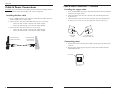
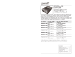
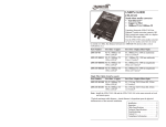
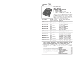
NETWORK SERVICES
LPS1000A User’s Guide
The LPS1000A media converters enable
businesses to provide power to network
devices over the existing CAT5 data
connection. The LPS1000A AC powered PoE
media converters combine data received over a
fiber optic link with -48VDC power, provides
power to Data Terminal Equipment (DTE) and
Power Devices (PD) over unshielded twisted
pair cable. These PoE converters are Power
Sourcing Equipment (PSE) and are fully compatible with Powered Devices (PD) that
comply with the IEEE802.3af standard. In addition, these converters have PD signature
sensing and power monitoring features per the IEEE 802.3af standard.
Part Number
LPS1000A-MM
LPS1000A-SM
LPS1000A-1SFP
LPS1000A-2SFP
Port One - Copper Port Two - Fiber
10/100/1000Base-T
RJ-45
SC, 1000Base-SX, 850 multimode
100 m (328ft.)*
62.5μm: 220m (722ft)
50μm: 550m (1804ft)
RJ-45
SC, 1000Base-LX, 1310 single mode
100 m (328 ft.)*
10km (6.2 miles)
RJ-45
100/1000Base-X
100 m (328 ft.)*
SFP slot (empty)
RJ-45
(2) 100/1000Base-X
100 m (328 ft.)*
SFP slots (empty)
*Cable distances are the typical maximum cable distance. Actual distance is dependent
upon the physical characteristics of the network installation.
Mounting options (sold separately)
Part Number
LPS1000-Wall
Description
Wall Mount Bracket
LPS1000-DINRAIL
DIN Rail Mtg. Bracket
Product Description/Features . .2
Enclosure Mounting . . . . . . . . . .5
DIP Switches . . . . . . . . . . . . . . .6
Cable & Power Connections . .8
Internal Jumpers . . . . . . . . . . .10
Operations . . . . . . . . . . . . . . .11
Cable Specifications . . . . . . . . .12
Technical Specification . . . . . .13
Troubleshooting . . . . . . . . . . .14
Contact Us . . . . . . . . . . . . . . .17
Compliance Information . . . . .18
LPS1000A
Product Description & Features
Product Description & Features -- Continued
Description -- continued
Description
LPS1000A-2SFP
LPS1000A-MM/-SM
Fiber Link
Active LED
Power LED
Fiber Port
TP Link
Active LED
Duplex
Power Over
RJ-45 Port Ethernet LED
Power LED
Fiber Link
Active LEDs
PWR
PWR
LACT
100/1000 Base-X
LACT
LACT
DUP
10/100/1000
Base-T
POE PWR
ERROR
DUP
PORT 1
Rear Panel
8-Position Switch
LPS1000A-1SFP
Power LED
PWR
Fiber Link
Active LED
POE PWR
ERROR
Power Inlet
Rear Panel
14-Position Switch
Product features
TP Link
Active LED
Duplex
SFP Port
RJ-45 Port
Power Over
Ethernet LED
100/1000 Base-X
LACT
10/100/1000
Base-T
PORT 1
Front Panel
Front Panel
Power Inlet
Power Over
Ethernet LED
100/1000 Base-X
LACT
LACT
1000Base-X
TP Link
Active LED
Duplex
LED RJ-45 Port
SFP Ports
LACT
DUP
10/100/1000
Base-T
POE PWR
ERROR
Front Panel
AutoCross
The AutoCross™ feature allows either straight-through (MDI) or crossover (MDI-X)
cables to be used when connecting to 10/100Base-TX devices, such as wireless access
points, VoIP phones, network cameras, etc. AutoCross determines the characteristics of
the cable connection and automatically configures the unit to link up, regardless of the
cable configuration devices.
Automatic Link Restoration
Black Box converters will automatically re-establish link in all network conditions:
• Without a device reset, the converters will automatically re-establish the link when
connected to switches after a link loss.
• With Auto-Negotiation enabled, automatic link restoration allows using AutoNegotiation with Link Loss Notification.
• With Link Pass-Through enabled in both directions, automatic link restoration
allows using Link Loss Notification in both directions.
Power Inlet
Rear Panel
10 Position Switch
Auto-Negotiation
The Auto-Negotiation feature allows the media converter to bring up the copper link to
the highest speed and mode possible for all the attached network devices.
Single Pair Power Insertion (IEEE802.3af)
PD Detection Signature (IEEE802.3af)
2
24-hour Technical Support: 1-724-746-5500
24-hour Technical Support: 1-724-746-5500
3
LPS1000A
Product Description & Features -- Continued
Product features -- continued
Over Current Protection/Under Current Detection (IEEE802.3af)
Link Pass-Through
The Link Pass-Through allows the media converter to monitor both the fiber and
copper RX (receive) ports for loss of signal. In the event of a loss of an RX signal
on one media port, the media converter will automatically disable the TX
(transmit) signal of the other media port, thus, “passing through” the link loss.
The far-end device is automatically notified of the link loss, which prevents the
loss of valuable data unknowingly transmitted over an invalid link. See diagram
below.
media converter A
disables the fiber TX link
Near-End
Device
1
Media
Converter A
2
Media
Converter B
original fault
on the copper link
4
Optional vertical wall mounting
CAUTION: Make sure that the hardware used for wall mounting can support the
weight of the LPS1000A once mounted. Failure to observe this caution could result in
damage to the equipment.
1. Orient the device as shown in the illustration below.
2. Remove the two #4 Philips head screws securing the cover to the device.
3. Position one side of the bracket assembly as shown in the illustration and
mount it to the device, using the the two #4 Philips head screws.
4. Do Steps 1 thru 3 to mount the bracket to the other side of the device.
5. Position the device on the mounting surface.
media converter B
loses the fiber RX link
3
Enclosure Mounting
6. Mount the device to the wall.
Far-End
Device
media converter B
disables the copper link
WMBL
Wall-Mount Bracket
Power Detect Reset
With the PSE/LTP switch enabled, a loss of the Fiber RX link will disable PSE power
output on the UTP power for 2 seconds to allow the remote device to reinitialize.
Fiber redundancy
The LPS1000A-2SFP media converter has two fiber SFP ports: one can be configured
as the primary port and one as the secondary port. When redundancy is enabled (SW14
Down, model LPS1000A-2SFP), any fault on the primary port results in the secondary
port becoming operational. When redundancy is disabled, the device operates as a
three-port switch.
Full-Duplex network
In a full-duplex network, maximum cable lengths are determined by the type of cables
that are used. (The 512-Bit Rule does not apply in a full-duplex network.)
Half-Duplex network (512-Bit Rule)
In a half-duplex network, the maximum cable lengths are determined by the round trip
delay limitations of each Fast Ethernet collision domain. (A collision domain is the
longest path between any two terminal devices, e.g., a terminal, switch, router, etc.)
Chassis Cover
Screws (Qty 4)
The 512-Bit Rule determines the maximum length of cable permitted by calculating
the round-trip delay in bit-times (BT) of a particular collision domain. If the result is
less than or equal to 512 BT, the path is good.
4
24-hour Technical Support: 1-724-746-5500
24-hour Technical Support: 1-724-746-5500
5
LPS1000A
DIP Switches
Installation -- Continued
CAUTION: All installation and service must be performed by qualified service
personnel. Read and follow all warning notices and instructions marked on the product
and included in this manual.
Setting the configuration switches -- continued
LPS1000A-2SFP
SW1. TP Auto-Negotiation: UP = Enable, DOWN Disabled
Setting the configuration switches
The configuration switches are located on the back panel of the
LPS1000A media converters. Use a small, flat-blade screwdriver to
set the switches.
SW2. TP Speed: UP = 100Mbs, DOWN = 10Mbs
(SW1 DOWN only)
SW3. TP Duplex: UP = Full, DOWN = Half
(SW1 DOWN only)
SW4. Fiber 1 Mode: 1000X/SGMII, UP = 1000X, DOWN = SGMII
Switch
Key
SW5. Fiber 1: Speed, UP = 1000Mbs, DOWN = 100Mbs (SW4 UP only)
SW6. Fiber 1: Duplex, UP = Full, DOWN = Half
Up
Down
(SW4 UP, SW5 DOWN only)
SW7. PSE Power: UP = Enabled, DOWN = Disabled
SW8. Unused
SW9. Unused
LPS1000A-MM/-SM
SW1. TP Auto-Negotiation: UP = Enable, DOWN = Disabled
SW2. TP Speed: UP = 100Mbs, DOWN =10Mbs (SW1 DOWN Only)
SW3. TP Duplex: UP = Full, DOWN = Half
(SW1 DOWN Only)
SW4. PSE Enable: UP = ON, DOWN = Disabled
SW5. POE power off LPT: UP = Disabled, DOWN = Enabled
SW6. LPT: UP = Enable, DOWN = Disable
SW7. Unused
SW8. Unused
SW10. Unused
SW11. Fiber 2 1000X/SGMII: UP = 1000X, DOWN = SGMII
SW12. Fiber 2 Speed: UP = 1000Mbs, DOWN = 100Mbs (1000x mode only, SW1 UP)
SW13. Fiber 2 Duplex: UP = Full, DOWN = Half
(SW11 UP, SW12 DOWN)
SW14. SFP Redundancy: UP = Disabled, DOWN = Enabled
Up
Down
Up
Down
LPS1000A-1SFP
SW1. TP Auto-Negotiation: UP = Enable, DOWN Disabled
SW2. TP Speed: UP = 100Mbs, DOWN = 10Mbs
(SW1 DOWN only)
SW3. TP Duplex: UP = Full, DOWN = Half
(SW1 DOWN only)
SW4. Fiber 1 Mode: 1000X/SGMII, UP = 1000X, DOWN = SGMII
SW5. Fiber 1: Speed, UP = 1000Mbs, DOWN = 100Mbs (SW4 UP only)
SW6. Fiber 1: Duplex, UP = Full, DOWN = Half
(SW4 UP, SW5 DOWN only)
SW7. PSE Power: UP = Enabled, DOWN = Disabled
SW8. POE Power off LPT Power: UP = Disabled, DOWN = Enabled
SW9. LPT: UP = Disabled, DOWN = Enabled
SW10. Unused
Up
Down
6
24-hour Technical Support: 1-724-746-5500
24-hour Technical Support: 1-724-746-5500
7
LPS1000A
Cable & Power Connections
CAUTION: Associated Ethernet wiring shall be limited to inside the building. Failure to
observe this caution could result in damage to the connected equipment.
Cable & Power Connections -- Continued
Installing the copper cable
1. Locate 10/100/100Base-TX copper cables with male, RJ-45 connectors installed
at both ends. See Figure below.
2. Connect the RJ-45 connector at one end of the cable to the RJ-45 port on the
media converter.
Installing the fiber cable
1. Locate a 100Base-FX fiber cable with male, two-stranded TX to RX connectors
installed at both ends. See Figure below.
2. Connect the fiber cables to the LPS1000A media converter as described:
•
Connect the male TX cable connector to the female TX port.
•
Connect the male RX cable connector to the female RX port.
3. Connect the fiber cables to the other device as described:
•
Connect the male TX cable connector to the female RX port.
•
Connect the male RX cable connector to the female TX port.
3. Connect the RJ-45 connector at the other end of the cable to the RJ-45 port on
the other device (wireless access point, VoIP phone, network camera, etc.).
RJ-45 port
on the media
converter
Connect fiber cable
to PCM card as shown.
Connect fiber cable
to other Network
device as shown
Connecting power
RX
RX
TX
RJ-45 port
on the other device
(switch, work station, etc.)
TX
1. Insert the barrel connector of the power adapter into the power port of the barrel
connector.
2. Plug the power adapter plug into AC power and the power LED on the front
panel should turn ON.
Power Inlet
Rear View
8
24-hour Technical Support: 1-724-746-5500
24-hour Technical Support: 1-724-746-5500
9
LPS1000A
Internal Jumpers
Operation
Power over Ethernet (PoE)
LEDs
The LPS1000A media converter transmits electrical power along with data to
remote devices over standard twisted-pair cable in an Ethernet network.
See individual LPS1000A faceplate for LED placements. The table below explains
what the LED functions indicate.
Note: Legacy powered devices that are not IEEE802.3af compliant can be power
provided that the polarity matches that list below.
LEDs
Description
TP Link/Activity
Green:
Yellow:
Green:
Yellow:
Green:
OFF:
ON Steady:
1 flash:
There are two modes of transmitting 48VDC PoE as defined in IEEE 802.3af:
Alternative A (default) uses pins 1&2(+), 3&6(-) to transmit data and power.
Alternative B uses pins 4&5(+), 7&8(-) to transmit power without data. These are
the spare pairs in 10BASE-T and 100BASE-TX device configurations; therefore,
Mode B requires a 4-pair cable.
TP Duplex
TP PSE
To set A or B PoE alternatives, do the following:
1. Remove the 4 screws on the and then remove the cover from the media
converter.
3. Set jumpers 2, 3, and 4 to the same side, either (A or B). See diagram below.
Pin Numbers
A
B
A
B
2
1
3
A
B
2
3
A
B
J3
J3
1
1000Mbs: ON link, BLINK activity
10 or 100Mbs: ON link, BLINK activity
Power ON
J2
J2
1
Fiber
Link/Activity
Power
Alternative B
1 2
3
Green
Yellow
Green
2 flashes:
2. Locate the 3 header connects J2, J3, and J4 on the circuit board.
(Default) Alternative A
1 2
3
5 flashes:
1000Mbs: ON link, BLINK activity
10 or 100Mbs: ON link, BLINK activity
Full duplex
Half duplex
Flashing indications every 1.2 seconds
Not powering an end device
Powering an end device
End device signature resistance is to low (300
ohm to 15K ohm detected)
End device signature resistance is to high (33K
ohm to 500K ohm detected)
Power overload fault
2
1
3
A
B
2
3
A
B
J4
J4
AutoCross
AutoCross
1
2
3
1
J8
2
3
(Default) Enabled
Disabled
J8
POE PSE legacy detection
POE PSE Legacy detection (Default)
1
2
No Jumper: Legacy Bias Current Detect Mode
3
1
2
3
J9
J9
Legacy Large Capacitor Detect Mode
1
2
3
J9
10
24-hour Technical Support: 1-724-746-5500
24-hour Technical Support: 1-724-746-5500
11
LPS1000A
Cable Specifications
Technical Specifications
The physical characteristics must meet or exceed IEEE 802.3™ specifications.
Standards:
Copper cable
Category 5: (Minimum Requirement)
Gauge: 24 to 22 AWG
Attenuation : 22.0 dB /100m @ 100 MHz
• Straight-through OR crossover twisted-pair cable may be used.
• Shielded twisted-pair (STP) OR unshielded Twisted-pair (UTP) may be used.
• Pins 1&2 and 3&6 are the two active pairs in an Ethernet network .
• RJ-45 Pin-out: Pin 1 = TD+, Pin 2 = TD-, Pin 3 = RD+, Pin 6 = RD• Use only dedicated wire pairs for the active pins:
(e.g., blue/white & white/blue, orange/white & white/orange, etc.)
• Do not use flat or silver satin wire.
Straight-Through Cable
Crossover Cable
Twisted Pair #1
1
2
1
2
Twisted Pair #1
1
2
1
2
Twisted Pair #2
3
6
3
6
Twisted Pair #2
3
6
3
6
Fiber cables
12
For use with Black Box Model LPS1000A or equivalent:
Bit Error Rate:
Single mode fiber (recommended):
Multimode fiber (recommended):
Multimode fiber (optional):
<10-9
9 µm
62.5/125 µm
100/140, 85/140, 50/125 µm
LPS1000A-MM
Fiber-optic Transmitter Power:
Fiber-optic Receiver Sensitivity:
Link Budget:
850 nm multimode
min: -9.5 dBm
min: -17.0 dBm
7.5.0 dB
LPS1000A-SM
Fiber-optic Transmitter Power:
Fiber-optic Receiver Sensitivity:
Link Budget:
1310 nm multimode
min: -9.5 dBm
max: -3.0 dBm
min: -20.0 dBm
max: -3.0 dBm
10.5 dB
24-hour Technical Support: 1-724-746-5500
max: -4.0 dBm
max: 0.0 dBm
IEEE 802.3, IEEE 802.3af
Data rate:
10/100/1000 Mb/s
Packet size (Max):
1632 bytes untagged, 1628 bytes tagged
Mac address:
8K
Dimensions:
5.1" x 4.3” x 1" (129.54mm x 109.2mm x 25.4mm)
Weight:
2 lbs. (0.90 kg) approximately
Power consumption:
20W max
Power supply:
Power Adaptor (supplied): Input 100-250 VAC
PSE power output:
15.4W
Environment
Ambient temp:
Storage temp:
Humidity:
Altitude:
0 to 40°C (32 to 104°F )
-25 to 85°C (-13 to 185°F )
5 to 95%, non-condensing
0 to 10,000 feet
MTBF*:
42,053 MIL217F2 Hours
115,646 Bellcore Hours
Warranty:
Lifetime
WARNING: Visible and invisible laser radiation when open. Do not stare into the
beam or view the beam directly with optical instruments. Failure to observe this
warning could result in an eye injury or blindness.
WARNING: Use of controls, adjustments or the performance of procedures other than
those specified herein may result in hazardous radiation exposure.
*MTBF is estimated using the predictability method. This method is based on MIL217F and Bellcore standards at 40°C ambient temperature, typical enclosure heat rise
of 10°C, and nominal operating conditions and parameters. Installation and
configuration specific MTBF estimates are available upon request. Contact Technical
Support.
24-hour Technical Support: 1-724-746-5500
13
LPS1000A
Technical Specifications -- continued
IMPORTANT: Copper based media ports, e.g., Twisted Pair (TP) Ethernet, USB,
RS232, RS422, RS485, DS1, DS3, Video Coax, etc., are intended to be connected to
intra-building (inside plant) link segments that are not subject to lightening transients
or power faults. Copper based media ports, e.g., Twisted Pair (TP) Ethernet, USB,
RS232, RS422, RS485, DS1, DS3, Video Coax, etc., are NOT to be connected to interbuilding (outside plant) link segments that are subject to lightening transients or power
faults. Failure to observe this caution could result in damage to equipment.
Troubleshooting -- continued
4.
Is the FL LINK LED ON?
NO
•
Check the fiber cables for proper connection.
•
Verify that the TX and RX cables on the media converter are connected to
the RX and TX ports, respectively, on the other device.
•
Disconnect and reconnect the fiber cable to restart the initialization
process.
•
Restart the attached device to restart the initialization process.
•
Contact 24-hour technical support : 1-724-746-5500
YES
•
Proceed to step 5.
5.
Is data being passed through the device?
NO
•
Ensure the Powered Device (PD) IEEE 802.3af compliant.
•
Ensure the load to the Powered Device (PD) is less than 0.4 Amp.
•
Is a data source connected; if not, connect a data source to the media
converter.
•
Is the data source active; if not, start sending data.
•
Are the FX and TX LACT LEDs flashing?
•
Contact 24-hour technical support : 1-724-746-5500
Troubleshooting
If the media converter fails, isolate and correct the fault by determining the answers to
the following questions and then take the indicated action:
1.
Is the media converter power LED ON?
NO:
•
Is the barrel connector fully inserted into the media converter?
•
Is the adapter plugged into an AC outlet; if not, plug it into the outlet.
•
Is the AC outlet active; if not, check the outlet’s circuit beaker?
•
Contact 24-hour technical support : 1-724-746-5500
YES
•
Proceed to step 2.
2.
Is the POE LED ON?
NO
•
Is there an active (connected to anther device ) RJ-45 cable inserted into
the media converter's TX port; if not, insert the cable accordingly.
Is the power turned ON to the other device?
•
Contact 24-hour technical support : 1-724-746-5500
YES
•
Go to step 3.
3.
Is the TX LACT LED ON
NO
•
Check the twisted pair cables for proper installation in the device at both
ends.
•
Disconnect and reconnect the twisted pair cable to restart the initialization
process.
•
Restart the attached device to restart the initialization process.
•
Check that the AutoCross switch is in the UP position (enabled).
•
Contact 24-hour technical support : 1-724-746-5500
YES
•
Go to step 4.
14
24-hour Technical Support: 1-724-746-5500
24-hour Technical Support: 1-724-746-5500
15
LPS1000A
Declaration of Conformity
Declaration of Conformity
NETWORK SERVICES
Name of Mfg:
Black Box Corporation
1000 Park Drive, Lawrence PA U.S.A.
Model:
LPS1000A Series Media Converters
Part Number(s):
LPS1000A-MM, LPS1000A-SM, LPS1000A-1SFP, LPS1000A-2SFP
Regulation:
EMC Directive 89/336/EEC
Purpose: To declare that the LPS1000A to which this declaration refers is in conformity
with the following standards.
CISPR22:2005 + A1:2005; EN55022:2006 Class A; EN55024:1998+A1:2001+A2:2008
I, the undersigned, hereby declare that the equipment specified above conforms to the above
Directive(s) and Standard(s).
Contact Us
Address
Black Box Corporation
1000 Park Drive
Lawrence, PA 15055-1018
Toll free:
877-877-2269
Technical support
Technical support is available 24 hours a day.
U.S.A.:
1-724-746-5500
June, 2008
Stephen Anderson, Vice-President of Engineering
16
24-hour Technical Support: 1-724-746-5500
Date
24-hour Technical Support: 1-724-746-5500
17
LPS1000A
Compliance Information
CE Mark
FCC regulations
This equipment has been tested and found to comply with the limits for a Class A digital device,
pursuant to part 15 of the FCC rules. These limits are designed to provide reasonable protection
against harmful interference when the equipment is operated in a commercial environment. This
equipment generates, uses, and can radiate radio frequency energy and, if not installed and used in
accordance with the instruction manual, may cause harmful interference to radio communications.
Operation of this equipment in a residential area is likely to cause harmful interference, in which
case the user will be required to correct the interference at the user's own expense.
Canadian regulations
This digital apparatus does not exceed the Class A limits for radio noise for digital apparatus set out
on the radio interference regulations of the Canadian Department of Communications.
Le présent appareil numérique n'émet pas de bruits radioélectriques dépassant les limites
applicables aux appareils numériques de la Class A prescrites dans le Règlement sur le brouillage
radioélectrique édicté par le ministère des Communications du Canada.
Compliance Information -- Continued
European regulations
Warning
This is a Class A product. In a domestic environment this product may cause radio interference in
which case the user may be required to take adequate measures.
Achtung !
Dieses ist ein Gerät der Funkstörgrenzwert klasse B. In Wohnbereichen können bei Betrieb dieses
Gerätes Rundfunkstörungen auftreten. In diesem Fäll ist der Benutzer für Gegenmaßnahmen
verantwortlich.
Attention !
Ceci est un produit de Classe A. Dans un environment domestique, ce produit risque de créer des
interférences radioélectriques, il appartiendra alors à l'utilsateur de prende les measures spécifiques
appropriées.
In accordance with European Union Directive 2002/96/EC of the European Parliament
and of the Council of 27 January 2003, Black Box will accept post usage returns of this
product for proper disposal. The contact information for this activity can be found in
the 'Contact Us' portion of this document.
CAUTION: RJ connectors are NOT INTENDED FOR CONNECTION TO THE
PUBLIC TELEPHONE NETWORK. Failure to observe this caution could result in
damage to the public telephone network.
Der Anschluss dieses Gerätes an ein öffentlickes Telekommunikationsnetz in den EGMitgliedstaaten verstösst gegen die jeweligen einzelstaatlichen Gesetze zur Anwendung der
Richtlinie 91/263/EWG zur Angleichung der Rechtsvorschriften der Mitgliedstaaten über
Telekommunikationsendeinrichtungen einschliesslich der gegenseitigen Anerkennung ihrer
Konformität.
18
24-hour Technical Support: 1-724-746-5500
24-hour Technical Support: 1-724-746-5500
19
LPS1000A
Trademark notice
All registered trademarks and trademarks are the property of their respective owners.
Copyright restrictions
© 2009 Black Box.
All rights reserved. No part of this work may be reproduced or used in any form or by any means graphic, electronic, or mechanical - without written permission from Black Box.
20
Printed in the U.S.A.
33436.A