1
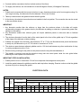
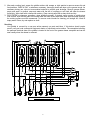
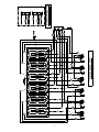
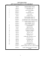
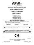
IMPORTANT
FOR FUTURE REFERENCE
Please complete this information
and retain this manual for the life
of the equipment.
MODEL #———————————————————
SERIAL #———————————————————
DATE PURCHASED——————————————
For Warranty Service and/or Parts this
information is required.
PRODUCT MANUAL
Safety Instructions
Installation Instructions
Operation Instructions
Maintenance Instructions
Replacement Parts List
Warranty/Service Information
ELECTRIC GRIDDLES, DROP-IN STYLE
Model: EGD-48
And
Model: EGD-72
FOR YOUR SAFETY
Do not store or use gasoline or other flammable vapors or liquids in the vicinity of this or
any other appliance.
WARNING
Improper installation, adjustment,
alteration, service or maintenance can cause
property damage, injury or death. Read the
installation, operating and maintenance
instructions thoroughly before installing or servicing this equipment.
!
APW/WYOTT Foodservice Equipment Co.
P.O. Box 1829
Cheyenne, WY 82003
(307) 634-5801
FAX (307) 637-8071
! CAUTION
These models are designed, built and sold for commercial use. If these models are positioned so the general public can use
the equipment, make sure that all cautions, warnings and operating instructions are clearly posted near each unit so that
anyone using the equipment will use it correctly and not injure themselves or harm the equipment.
! WARNING
Improper installation, operation, service or maintenance can cause property damage, injury or death. Read
these instructions thoroughly before installing, operating, maintaining or servicing this equipment.
Install per the spacing requirements listed in the installation section of this manual. We strongly recommend
having a competent professional install this equipment. Such a person should be familiar with local gas
regulations. A gas company representative should approve the completed installation.
!
WARNING
FOR YOUR SAFETY DO NOT STORE OR USE GASOLINE OR OTHER FLAMMABLE LIQUIDS AND
VAPORS IN THE VICINITY OF THIS OR ANY OTHER APPLIANCE. KEEP THE AREA FREE AND
CLEAR OF COMBUSTIBLES. (SEE ANZI Z83.14B, 1991)
Instructions to be followed if any one smells gas should be posted in a prominent place. These may be
obtained from the gas supplier.
IMMEDIATELY INSPECT FOR SHIPPING DAMAGE
All containers should be examined for damage before and during unloading. The freight carrier has assumed responsibility for its safe transit and delivery. If equipment is received damaged, either apparent or concealed, a claim must be
made with the delivering carrier.
A)
Apparent damage or loss must be noted on the freight bill at the time of delivery. It must then be signed by the
carrier representative (Driver). If this is not done, the carrier may refuse the claim. The carrier can supply the necessary
forms. B) Concealed damage or loss if not apparent until after equipment is uncrated, a request for inspection must be
made to the carrier within 15 days. The carrier should arrange an inspection. Be certain to hold all contents and packaging material.
Installation and start-up should be performed by a qualified installer who thoroughly read, understands and follows these
instruction.
If you have questions concerning the installation, operation, maintenance or service of this product, write Technical Service Department APW/Wyott Foodservice Equipment Company, P.O. Box 1829, Cheyenne, WY 82003.
2
Congratulations on your purchase of APW/Wyott commercial cooking or refrigeration equipment. APW/Wyott takes
pride in the design and quality of our products. When used as intended and with proper care and maintenance, you will
experience years of reliable operation from this equipment. To assure best results, it is important that you read and
follow the instructions in this manual carefully.
TABLE OF CONTENTS:
Safety Precautions ........................................... 3
Specifications ................................................... 4
Installation .................................................... 4-6
Operating Information ...................................... 7
Cleaning / Maintenance................................. 7-8
Service / Repair ............................................... 8
Wiring Diagram, EGD-48 .................................. 8
Wiring Diagram, EGD-72.................................. 9
Parts Diagram ........................................... 10-11
Warranty ........................................................ 12
LOCATION OF DATA PLATE
The data plate is located on the front panel.
SAFETY PRECAUTIONS
Before installing and operating this equipment be sure everyone involved in its operation are fully trained and are aware of all precautions. Accidents and problems can result by a failure to follow fundamental rules and precautions.
The following words and symbols, found in this manual, alert you to hazards to the operator, service personnel or the equipment.
The words are defined as follows-.
! DANGER
This symbol warns of imminent hazard which will result in serious injury or death.
! WARNING
This symbol refers to a potential hazard or unsafe practice which could result in serious injury or death.
! CAUTION
This symbol refers to a potential hazard or unsafe practice which may result in minor or moderate injury or product or property
damage.
NOTICE
This symbol refers to information that needs special attention or must be fully understood even though not dangerous.
NOTICE
This product is intended for commercial use only. Not for household use.
! CAUTION
The models are designed, built and sold for commercial use. If these models are positioned so the general public can use the
equipment, make sure that all cautions, warnings and operating instructions are clearly posted near each unit so that anyone using the equipment will use it correctly and not injure themselves or harm the equipment.
! WARNING
SHOCK HAZARD
Do not open any panels that require the use of tools.
! WARNING
Improper installation, service, or maintenance can cause property damage, injury or death.
3
Specifications And Dimensions:
Model
EGD-48
EGD-72
EGD-72
Double Trough
Width
in. (mm)
Depth
in. (mm)
Height
in. (mm)
No. of
Elements
49.0/125
72.0/191
72.0/191
29.5/75
29.5/75
32.5/83
0.31/0.8
0.31/0.8
0.31/0.8
8
12
12
Griddle Surface Dimensions:
kW Per
Element
2.7
2.7
2.7
Total
kW
21.6
32.4
32.4
Model
Width in./cm
Depth in./cm
EGD-48
46.5/119
23.94/61
EGD-72
69.5/177
23.94/61
General Installation Instructions:
Caution:
DO NOT use an open flame to check for leaks. Check all gas piping for leaks with a soap and water solution
before operating unit.
NOTICE THE UNIT, WHEN INSTALLED, MUST BE ELECTRICALLY GROUNDED IN ACCORDANCE WITH LOCAL CODES, OR IN THE
ABSENCE OF LOCAL CODES, WITH THE NATIONAL ELECTRICAL CODE, ANSI/NFPA 70, LATEST EDITION.
CANADIAN INSTALLATION MUST COMPLY WITH THE CANADIAN ELECTRICAL CODE, CSA C22.2, AS APPLICABLE.
NOTICE Local codes regarding installation vary greatly from one area to another. The National Fire Protection Association, Inc., states in its
NFPA 96 latest edition that local codes are "authority having jurisdiction" when it comes to requirements for installation of equipment. Therefore, installations should comply with all Local codes.
General Installation Instructions:
With all the large holes cut out, the smaller control panels drilled, and the stiffening angle welded into place, the
fixture is now ready to receive the griddle.
1. The manufacturer furnishes a gasket or seal that must be placed around the perimeter of the hole in the top as
shown in Fig. 4. This gasket may be temporarily held in place with tape. Do not place the staple securing the
gasket ends on or near a corner.
2. A number of clamps, such as the one shown in Fig. 4, appear at intervals along the perimeter. Pull clamps
outward so the griddle frame clears them when it is dropped into place.
3. Drop the griddle into position by lowering it into the fixture top hole. Make sure the thermostat capillaries are
not kinked or pinched when setting the griddle in place. With the griddle in place, the gasket or seal becomes
compressed. See Fig. 5.
4. Slide the clamp inward so it engages the upper part of the protruding angle from the griddle frame. See Fig. 6.
Slide the clamp sideways so the notch on it locks against the reinforcement angle. This prevents the clamp
from sliding out.
5. Tighten the clamp screws against the angle as shown in Figure 6. This tightening forces the clamps to press
down on the griddle body frame extension. The griddle top is now drawn close to the fixture top, compressing
the gasket and forming an effective grease guard. Tighten at least one screw on each side before tightening
all screws. Do not exceed 60 in/lb torque when tightening bolts.
6. Slide the tray slide (grease drawer receptacle) through the cutout hole on the apron or front of the fixture,
resting it on the two “U” braces.
7. Mount the thermostats to the control panel and make the pilot light connections per the accompanying wire
diagram. Before making any electrical connections, check nameplate voltage (located on tray slide under
grease drawer) to ensure it matches voltage being applied.
8. Set the control panel in place and screw it to the apron using the ½-inch long thread forming screws.
9. Pull the tray slide against the back of the control panel and secure it with the appropriate screws.
10. Slide the grease drawer into place.
4
FIGURE 3
FIGURE 5
FIGURE 4
FIGURE 6
Electrical Connections
Terminal Box Location:
The terminal boxes can be located at either the left front or right rear of the griddle. When shipped from the
factory the device has the terminal box attached in the left front position. The box can be relocated to the
alternate position by removing two screws.
Loading:
Electrical loadings of the griddles covered by this instruction are tabulated below.
Fusing:
Griddle is not fused and must be connected to a properly fused circuit.
Grounding:
Griddle must be grounded in accordance with the National Electrical Code and applicable local codes.
U.L. CONDITIONS OF ACCEPTABILITY:
1. This equipment must be installed in an all metal fixture of steel or stainless steel construction, .078 inch thick
minimum for the top and supporting frame. Side enclosure to be at least 22 MSG minimum thickness.
2. A removable bottom enclosure must be provided under each drop-in unit and be made of metal construction of
at least 22 MSG minimum. If ventilating openings are provided in the bottom enclosure, they must not allow the
entrance of ¾-inch diameter rod nor be located directly below uninsulated live terminals.
3. Minimum spacing between griddle top edge and adjacent items should be: fixture back wall 1 ¾ inch, fixture
side enclosure 1 inch, front control panel 7/8 inch, other drop-in devices 1 inch.
5
4. Controls shall be mounted on the front vertical surface of the fixture.
5. For supply connections, use wire suitable for at least 90 degrees Celsuis (194 degrees Fahrenheit).
NOTES:
1. Griddle can be mounted with the trough in the front or rear, dimensions shown are for front trough mounting. For
rear trough mounting, this dimension must be between 7/8 inch and 2 inches.
2. Table top reinforcement and gasket furnished with the griddle.
3. At the factory, the electrical connection box was installed in the front position. The connection box can be moved
to the rear location shown.
IMPORTANT:
1. Any dimension smaller than the minimum or larger than the maximum shown in the table will require
corresponding changes to the grease chute by the fabricator by adding an extension to prevent the grease from
spilling into the cabinet.
2. Any dimensions smaller than minimum given will require additional panels or sides and back to facilitate
servicing.
3. The minimum dimension from the back of the control panel to the front of the griddle top is 7/8 inch regardless
of the shape of the bullnose or table overhang.
4. Griddles are shipped from the factory with dimension ”D” at 7 7/16 inch. Moveable braces permit the fabricator
to easily vary this dimension up to 10 7/16 inches in increments of ¾ inch.
5. The minimum space between adjacent griddles must be 1 5/8 inch and between any other combination of dropin cooking equipment must be 1 inch.
6. Electrical wiring crossing the tray slide is to be placed under the tray slide and not above it.
7. The installer or servicer must put the electrical wiring near the control panel inside the wire guide before
attaching the control panel to the fixture front.
IMPORTANT STEPS IN INSTALLATION:
1. Griddle position to be no closer than 7/8 inch from component frame edge and control panel.
2. Install the gasket between the griddle top and the table top before clamping. Exercise caution so that the griddle
top does not pinch or damage the gasket
ELECTRICAL DATA
PHASE-LOADING AND LINE AMPERES 50/60 HZ
NOMINAL AMPERES PER LINE
3-Phase Loading
3-Phase AC
1-Phase AC
Model
Number
Power
Input
(KW)
Y-Y
Y-Z
X-Z
X
Y
Z
X
Y
Z
X
Y
EGD48
21.6
10.8
5.4
5.4
69.0
69.0
45.0
60.0
60.0
39.0
30.0
30.0
EGD72
32.4
10.8
10.8
10.8
90.0
90.0
90.0
78.0
78.0
78.0
39.0
39.0
39.0
KW Per Phase
208 VOLTS
240 VOLTS
6
208
VOLT
240
VOLT
480
VOLT
Z
AC
AC
AC
20.0
104
90
45
156
135
68
480 VOLTS
OWNER’S INFORMATION
Cleaning the Griddle After Uncrating:
Before using for the first time, be sure to remove the factory-applied rust preventative compound. Add a mild
detergent to hot water and wash the griddle well. Rinse with a clean, damp cloth and wipe dry.
The Controls:
Turning the dial knob (recessed in the front control panel) controls the heat of the griddle surface. When at
least one control is turned on, a signal light in the upper left-hand corner of the control panel will glow
continuously. Thus, the operator knows at a glance whether or not the griddle is energized. Separate signal
light cycles with each control. Whenever the thermostat calls for heat, the signal light associated with it will
be on. Each thermostat controls twelve inches of griddle surface width. Thermostat temperature range is
200-450F +/- 10F.
Seasoning the Griddle Surface:
After thorough cleaning, the griddle is ready for seasoning. Preheat to 400F. When the dialed temperature is
reached as indicated by the signal lights going off, spread a light film of cooking oil or fat over the entire
surface of the griddle. In two minutes, wipe the griddle clean of excess oil. Repeat this operation. The griddle
is now ready for use.
Operating Instructions:
1. Preheat griddle (preheat time, 77F - 350F, approximately 8 minutes). Set the thermostat dials at the correct
griddling temperature for the food to be cooked. A red light will flash on automatically for each section of the
griddle when the dial is set and will flash off when the section has reached the dialed temperature. (The
signal light will flash on and off during the cooking operation to show that correct temperature is being
maintained.) You are now ready to load the griddle.
2. Load Griddle. After preheating, load griddle and cook according to recipe. Turn foods halfway through
cooking time unless otherwise specified in recipe.
3. Economy Hint. Turn griddle OFF (or to lowest thermostat setting) during idle periods.
MODEL EGD-48
CAPACITIES
MEATS
Hamburgers (2 ½-oz servings, 3 ½” diam.)
Minute Steaks (4-oz. steaks, ½” thick) .......
Beef Tenderloin (5-oz. steaks, 1” thick)......
Liver (3-oz. slices, 3/8” thick) .....................
Bacon (22 to 32 slices per lb.) ...................
Pork Link Sausages (Fresh, 1 ¼-oz., 3 ½”
long)
Hot Dogs (split) ..........................................
Ham Steaks (1-lb, tenderized, ½” thick) .....
OTHER FOODS
Eggs, Fried ...............................................
Pancakes (4” diam.) ..................................
Fried Potatoes, Blanched (Servings) .........
Fried Onions, Blanched (Servings) ............
QTY
Per
Load
65
24
48
36
3 ½ lbs
12 lbs
64
24
MODEL EGD-72
APPROX QTY
Hourly
Per
Production Load
APPROX
Hourly
Production
BOTH MODELS
Cooking
Time
& Temp
. . . . 945+
. . . . 360+
. . . . 280+
. . . . 450+
. . . . 30 lbs.
. . . . 70 lbs
. . . . 900+
. . . . 325+
86 . . . . 1300+
32 . . . . 400+
64 . . . . 370+
48 . . . . 600+
4-2/3 lbs . . . . 40 lbs
16 lbs . . . . 93 lbs
86 . . . . 1200+
32 . . . . 433+
3 min. at 350F
4 min. at 350F
8 min. at 350F-360F
3-4 min. at 350F
5-6 min. at 350F
10 min. at 325F
3 min. at 350F
4 min. at 350F
64 . . . . 900+
40 . . . . 450+
51 . . . . 750+
75-77 . . . . 1100+
32 . . . . 600+
86 . . . . 1200+
53 . . . . 600+
67-80 . . . . 1000+
100-106 . . . . 1470+
43 . . . . 852+
3 min. at 300F
3-4 min. at 360F-375F
4 min. at 375F
3 min. at 340F
2 min. at 350F
Care and Cleaning:
1. IMPORTANT: At the end of each day’s operation, turn all temperature controls to “OFF.”
7
2. After each cooking load, scrape the griddle surface with scraper or rigid spatula to remove excess fat and
food particles. ONCE A DAY, or whenever necessary, thoroughly clean and wipe out the grease trough. As
necessary during use, wipe out accumulated material to provide good drainage. Remove grease drawer,
empty and wash. In general, soap and water with the aid of a sponge or soft cloth will clean the drawer
thoroughly. Wipe clean with a damp cloth and dry. Clean control panel with a damp cloth and dry.
3. EACH WEEK, or whenever necessary, clean griddle thoroughly. If desired, use a pumice or griddle stone
over surface. Rub with the grain of the metal while still warm. Avoid steel wool! After each thorough cleaning,
the cooking surface must be reseasoned. To remove control knobs for cleaning, pull straight out. Wash in
soapy water. Rinse, dry and replace on shaft.
Servicing
Your griddle is covered by a one-year written warranty on parts and labor. If this device should require
service, call your local commercial equipment dealer or authorized service station. The nameplate indicating
the pertinent electrical data of the griddle is located in the front of the grease drawer receptacle and can be
seen readily when the drawer is removed.
WIRING DIAGRAM, EGD-48
8
9
WIRING DIAGRAM, EGD-72
ALTERNATE WIRING FOR
TWO POWER SUPPLIES
PARTS BREAK DOWN
DROP-IN ELECTRIC GRIDDLES, EGD-48 AND EGD-72
ITEM NUMBER
PART NUMBER
DESCRIPTION
1
14397-25
HEATING ELEMENT, 208 VOLT
14397-26
HEATING ELEMENT, 240 VOLT
2
642567-01
PRESSURE PLATE
3
646378-03
BULB CLAMP ASSEMBLY
4
646251-01
BAFFLE
5
642578-01
TERMINAL BLOCK BOX
6
642579-01
BOX COVER
7
11260-35
TERMINAL BLOCK
8
647392-01
BOTTOM PANEL, EGD-48, R.H.
647395-01
BOTTOM PANEL, EGD-48, L.H.
642584-02
BOTTOM PANEL, EGD-72, SINGLE TROUGH
642584-01
BOTTOM PANEL, EGD-72, DOUBLE TROUGH
643066-01
BRACE ASSEMBLY, EGD-48
643356-03
BRACE ASSEMBLY, EGD-72
10
653844-01
CONTROL PANEL ASSEMBLY
11
642625-09
KNOB ASSEMBLY
12
15139-03
INDICATOR LIGHT
13
31100-82
CONTROL PANEL SEAL
19
644635-05
THERMOSTAT ASSEMBLY
20
82111-00
SCREW, 1/4-20 X 3/4
21
84315-00
HEX NUT, 1/4-20
23
31101-30
SCREW, 10-32 X 1/2
24
84171-00
HEX NUT, 10-32
25
81413-00
SCREW, SELF-TAPPING, 8-32 X 1/2
26
84364-00
WING NUT, 5/16-18
27
85195-00
FLAT WASHER, 5/16
28
84317-00
HEX NUT, 1/4-20
29
84362-00
HEX NUT, 5/16-18
30
85196-00
FLAT WASHER, 1/4
31
642626-06
GASKET, GRIDDLE TOP, EGD-48
642626-07
GASKET, GRIDDLE TOP, EGD-72, SINGLE TROUGH
642626-10
GASKET, GRIDDLE TOP, EGD-72, DOUBLE
TROUGH
9
10
PARTS PICTURE GOES HERE
11
APW/WYOTT EQUIPMENT LIMITED WARRANTY
APW/WYOTT Foodservice Equipment Company warrants its equipment against defects in materials and workmanship, subject to the following conditions:
This warranty applies to the original owner only and is not assignable.
Should any product fail to function in its intended manner under normal use within the limits defined in this warranty, at the option of APW/
WYOTT such product will be repaired or replaced by APW/WYOTT or its Authorized Service Agency. APW/WYOTT will only be responsible for charges incurred or service performed by its Authorized Agencies. The use of other than APW/WYOTT Authorized Service Agencies will void this warranty and APW/WYOTT will not be responsible for such work or any charges associated with same. The closest
APW/WYOTT Authorized Service Agency must be used.
This warranty covers products shipped into the 48 contiguous United States, Hawaii, metropolitan areas of Alaska and Canada. There will
be no labor coverage for equipment located on any island not connected by roadway to the mainland.
TIME PERIOD:
One-year parts, one-year labor, effective from the date of purchase by the original owner. The Authorized Service Agency may, at their
option, require proof of purchase. Parts replaced under this warranty are warranted for the unexpired portion of the original product warranty only.
EXCEPTIONS:
*Gas/Electric Cookline - Models GCB, GCRB, GF, GGM, GGT, GHP-H, GWW, EBC, EF, EG, EHP, EWW Three (3) Year Warranty on all
component part, except switches and thermostats. (2 additional years on parts only - No labor on second or third year.) *Heat Strips Models FD - Two (2) Year Warranty on element only - No labor second year. *Glass Windows, Door Seals, Rubber Seals, Light Bulbs,
Broiler Briquettes 90 Day Material Only - No labor.
In all cases parts covered by extended warranty will be shipped FOB the factory after the first year.
PORTABLE CARRY-IN PRODUCTS
Equipment weighing over 70 pounds or permanently installed will be serviced on-site as per the terms of this warranty. Equipment weighing 70 pounds or under, and which is not permanently installed i.e., with cord and plug, is considered portable and is subject to the following warranty handling limitations.
If portable equipment fails to operate in its intended manner on the first day of connection, or use, at APW/WYOTT's option or its Authorized Service Agency, it will be serviced on-site or replaced.
From day two through the conclusion of this warranty, portable units must be taken or sent prepaid to the APW/WYOTT Authorized Service Agency for in-warranty repairs. No mileage or travel charges are allowed on portable units after the first day of use. If the customer
wants on-site service they may receive same by paying the travel and mileage charges.
EXCLUSIONS:
The following conditions are not covered by warranty.
*Equipment failure relating to improper installation, improper utility connection or supply and problems due to ventilation.
*Equipment that has not been properly maintained, calibration of controls, adjustments, damage from improper cleaning and water damaged controls.
*Equipment that has not been used in an appropriate manner, or has been subject to misuse or misapplication, neglect, abuse,
accident, alteration, negligence, damage during transit, delivery or installation, fire, flood, not or act of God.
*Equipment that has had the model number or serial number removed or altered.
If the equipment has been changed, altered, modified or repaired by other than a qualified service technician during or after the warranty
period then the manufacturer shall not be liable for any damages to any person or property which may result from the use of the equipment thereafter.
This warranty does not cover services performed at overtime or premium labor rates. Should service be required at times which normally
involve overtime or premium labor rates, the owner shall be charged for the difference between normal service rates and such premium
rates APW/WYOTT does not assume any liability for extended delays in replacing or repairing any items beyond its control.
In all cases the use of other than APW/WYOTT authorized OEM replacement parts will void this warranty.
This equipment is intended for commercial use only. Warranty is void if equipment is installed in other than commercial application.
THE FOREGOING WARRANTY IS IN LIEU OF ANY AND ALL OTHER WARRANTIES EXPRESSED OR IMPLIED INCLUDING ANY IMPLIED WARRANTY OF MERCHANTABILITY OR FITNESS AND CONSTITUTES THE ENTIRE LIABILITY OF APW/WYOTT IN NO EVENT DOES THE LIMITED
WARRANTY EXTEND BEYOND THE TERMS STATED HEREIN.
P/N 88060-50
01/00
12