1
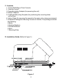
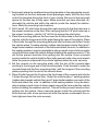
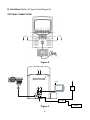
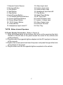
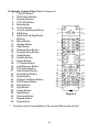
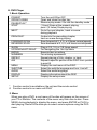
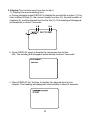
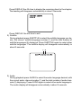
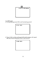
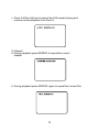
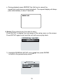
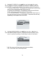
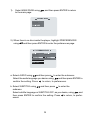
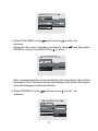
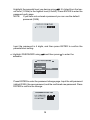
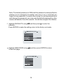
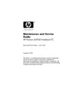
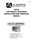
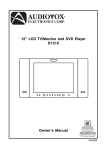
®
ELECTRONICS CORP.
DV9000
9” Color TV and DVD Player Floor Console
For Customer Service
Visit Our Website At
WWW.audiovox.com
Product Information, Photos,
FAQ’s Owner’s Manuals
Owner’s Manual
A. Introduction
The DV9000 is a self-contained entertainment center for your vehicle which
will make your road trips enjoyable. This versatile floor console incorporates a
9” color TV with a built-in DVD Player, complete with speakers, foil antenna,
external antenna jack, headphone jacks, AV inputs, AV outputs and a remote
control. The DV9000 is easily installed between the front seats of any mini or
full size van. The console is constructed to provide years of enjoyment. Standardized design and manufacture ensures reliability and longevity. Please read
the following instructions thoroughly for correct installation and proper operation. Store this manual in a convenient and safe place for future reference.
B. Cautions and Warnings
1. Installation
In order to maintain a safe mounting arrangement, this console must be secured to the floor of the vehicle according to Installation Guide contained in
this manual. Failure to do so may result in the console becoming a projectile
in the event of an accident.
Before working under the vehicle, block the wheels to prevent accidental move
ment of the vehicle which could result in injury. Before drilling any holes in the
vehicle, verify that the drill bit will not damage the frame rail(s) of the vehicle,
electrical wires, fuel lines, brake lines, hoses, exhaust system components or
any other items that will impair the operation of the vehicle. The console must
be secured to the floor panel of the vehicle. Check under the vehicle to ensure
that the holes will be in the proper locations. Also check under the carpet to
ensure that there are no wiring harnesses, fuel lines, etc. that could be damaged when drilling through the floor of the vehicle.
2. Power
Use only the supplied power cable supplied with this set to avoid electric
hazards. Always disconnect the unit from the cigarette lighter socket when it
is not in use.
2
3. Discs
Do not use irregularly shaped discs such as heart-or star-shaped discs as
they may cause the unit to malfunction. Do not stick paper, tape or glue on
the disc. Do not expose the disc to direct sunlight or heat sources such as
hot air ducts. Do not touch the surface of disc. Handle the disc by its edge.
Clean the disc by wiping the disc from the center out with a clean cloth.
Remove the disc from the unit and store it in its case after playing. Some
playback operations of discs may be intentionally fixed by software producers. Since this unit plays discs according to the disc contents the software
producers designed, some playback features may not be available. Also refer to the instructions supplied with the discs.
4.TV Reception
Due to the nature of TV signals, the vehicle’s motion, the direction the vehicle
is facing, the distance from transmitters, nearby surroundings and weather
may adversely affect TV reception. These conditions may result in picture roll,
poor reception (snowy picture) and momentary loss of color (especially when
the vehicle is in motion).
5. Headphones
Use caution when children wear headphones; as becoming entangled in the
wires could present a hazard.
6. Objects and Liquids
Keep strong magnets, heat sources, direct sunlight, and excessive dust away
from the unit. Do not push objects of any kind into the system through openings. Do not spill or spray liquid of any kind on or in the system (this may
result in a fire or electric shock). Do not place anything heavy on the unit. To
ensure proper ventilation and proper operation, never cover or block the slots
and openings with a cloth or other material.
7. Disassemble
To avoid harm from the laser beam assembly and to reduce the risk of electric shock, do not attempt to disassemble the cabinet. Contact qualified service personnel if your system is in need of repair.
8. Cleaning Unit
When cleaning, make sure the system is unplugged from power source. Do
not use liquid cleaners or aerosol cleaners. Use a cloth lightly dampened
with water for cleaning. Clean the exterior of the system only.
3
C. Contents
1. TV and DVD Player Floor Console
2. Remote Control
3. Cigarette Lighter Adapter (for powering the unit)
4. Owner’s Manual
5. Cardboard Mounting Template (for positioning the mounting holes
on the floor)
6. Velcro Strips (for securing the remote to the main unit or wherever desired)
7. Hardware Package for Securing Console to Vehicle. The package contains
the following:
6 Bolts
6 Sealing Washers
6 Fender Washers
6 Nuts
1 Mounting Plate
D. Installation Guide (Refer to Figure 1)
Figure 1
4
1. Temporarily place the cardboard mounting template in the appropriate mounting location on the floor between driver/passenger seats, with the four hole
end of the template facing the front of your vehicle. Be sure to leave enough
space for the disc tray to fully open. Make sure that you have checked underneath the vehicle and within the vehicle (under the carpet) for obstructions. Mark the mounting hole locations.
2. Drill 6 small 1/8” pilot holes though the marks and verify that the holes are in
the proper locations on the floor. After verifying that the 1/8” pilot holes are in
the proper locations, use the 1/4” drill bit to enlarge the pilot holes.
3. Place the mounting plate on the floor over the 4 holes close to the front of the
vehicle, with the tongue end of the plate facing the rear of the vehicle. Place
4 floor bolts through the mounting plate and into the holes just drilled. Under
the vehicle place 1 sealing washer (rubber side towards vehicle floor) and 1
large fender washer over each of the bolts and attach the nuts. In addition to
the sealing washer it may be desirable to place a small circle of silicon sealer
around the hole under the vehicle before installing the washers and nut. This
will further prevent moisture from getting into the vehicle. Have a second
person inside the vehicle hold the floor bolts securely with a box-end wrench
while the person underneath the vehicle tightens down the nuts securely.
4. Set the console on the mounting plate, with the slot of the console base
pointing to the tongue end of the mounting plate. Push forward to mate the
console base and the floor mounting plate, with the tongue of the mounting
plate projecting into the slot of the console base.
5. Place 2 bolts through the 2 holes in the front base of the console and into the
2 holes through the vertical floor. Under the vehicle place 1 sealing washer
(rubber side towards vehicle floor) and 1 large fender washer over each of the
bolts and attach the nuts. In addition to the sealing washer it may be desirable to place a small circle of silicon sealer around the hole under the vehicle
before installing the washers and nut. This will further prevent moisture from
getting into the vehicle. Have a second person inside the vehicle hold the
bolts securely with a box-end wrench while the person underneath the vehicle tightens down the nuts securely.
5
E. Unit View (Refer to Figure 2 and Figure 3)
OPTIONAL CONNECTIONS
Figure 2
24
12 Vdc
ANT
FM MOD
Figure 3
6
RADIO
13. Video Input Jack
14. Audio L Input Jack
15. Audio R Input Jack
16. Headphone Input Jack #2
17. Play Button
18. Open/Close Button
19. DC Input Jack
20. Audio R Output Jack
21. Audio L Output Jack
22. Video Output Jack
23. Antenna Terminal
24. Disc Tray
1. Remote Control Sensor
2. Previous Button
3. Play Button
4. Next Button
5. Stop Button
6. Auto Program Button
7. TV Channel Up/Down Buttons
8. Volume Up/Down Buttons
9. Picture Select Button
10. TV/AV Select Button
11. Power Button
12. Headphone Input Jack #1*
*NOTE: Mutes Internal Speakers
F. Power Supply Connection (Refer to Figure 3)
1. Open the access panel on the bottom rear of the unit by pressing the latch
located on the left side of the panel toward the center of the console and
pulling outward.
2. Plug one end of the cigarette lighter adapter into the DC input jack in the rear
of the console.
3. Replace the access panel and have the power cord pass through either hole
at the bottom of the panel.
4. Plug the other end into the cigarette lighter receptacle in the vehicle.
7
G. Remote Control View (Refer to Figure 4)
1. TV/DVD Button*
2. DVD Select Button
3. Number Buttons
4. TV/CATV Button
5. Mute Button
6. Picture Button
1
7. Volume Up/Down Buttons
2
8. AB Button
9. Up-Down/Left-Right/Enter
Buttons
10. Menu Button
3
11. Display Button
12. Stop Button
13. Reverse Scan Button
4
14. Forward Scan Button
5
6
15. Audio Button
16. Subtitle Button
7
17. Power Button
18. TV Select Button
8
19. Auto Memory Button
20. TV Display Button
9
21. Skip Search Button
10
22. Erase/Write Button
11
23. Sleep Button
12
24. Channel Up/Down Button
13
14
25. DVD Power Button
15
26. Setup Button
16
27. Play Button
28. Pause Button
29. Next Button
30. Previous Button
31. Repeat Button
32. Slow Button
*
17
18
19
20
21
22
23
24
25
PAUSE
Figure 4
Function control is available on the unit and the remote control
8
26
27
28
29
30
31
32
H. DVD Player
1. Basic Operation
POWER*
OPEN/CLOSE#
PAUSE/PLAY*
STOP*
NEXT*
PREVIOUS*
FORWARD SCAN
REVERSE SCAN
SLOW
UP/DOWN/LEFT/RIGHT
ENTER
NUMBERS
REPEAT
A-B
MENU
SUBTITLE
AUDIO
DISPLAY
SETUP
*
#
Turn the unit ON or OFF
Open and close the disc tray
Resume play mode / Go into the standby mode
(1 time) Stops at the present playing
point / (2 times) Stops playing
Go to the next chapter, track or scene
during playback
Go back to the preceding chapter,
track or scene during playing
Scan forward at 2, 4, 6, or 8 times normal speed
Scan backward at 2, 4, 6, or 8 times normal speed
Play at 1/2, 1/4, or 1/8 times speed
For Navigating the Set-Up Menu
Execute item or setting
For entering a password
Repeat playing of title, chapter, or track
Repeat a specific portion of the DISC from point A
to point B
Display the root menu of the DISC
Select the subtitle language and turn it on/off
Select the audio language
Display information about the DISC
Display the setup menu
Function control is available on the unit and the remote control
Function control is on main unit ONLY
2. Menu
When you play a DVD, a root menu of the disc will appear on the screen of
your TV or Monitor. The contents of the menu vary from disc-to-disc. Press
MENU during playback to display the menu, and press ENTER or PLAY to
start playing. Some DVDs allow you to select various options using the DVD
menu.
9
3. Display (The contents vary from disc-to-disc.)
1). Playing time and remaining time
a. During playback press DISPLAY to display the current title number (1), the
total number of titles (2), the current chapter number (3), the total number of
chapters (4), and the elapsed time for the title (5). The heading will disappear
automatically in about 3 seconds.
b. Press DISPLAY again to display the remaining time for the
title. The heading will disappear automatically in about 3 seconds.
TITLE REMAIN
c. Press DISPLAY the 3rd time to display the elapsed time for the
chapter. The heading will disappear automatically in about 3 seconds.
10
Press DISPLAY the 4th time to display the remaining time for the chapter.
The heading will disappear automatically in about 3 seconds.
Press DISPLAY the 5th time to exit.
2). Subtitle
During playback press SUBTITLE to select the subtitle language you desire, the current subtitle language number (1) and the total number of
subtitle languages (2) displayed. Press SUBTITLE again to select other
subtitle languages. The subtitle display will disappear automatically in
about 3 seconds.
3). Audio
During playback press AUDIO to select the audio language desired, with
the current audio channel number (1) and the total number of audio channels (2) displaying. Press AUDIO again to select other audio language’s.
The audio display will disappear automatically in about 3 seconds.
11
4). A-B Repeat
a. During playing press A-B to set the starting point A.
b. Press A-B to set the ending point B and the player will repeat
edly play the part between Point A and Point B.
12
c. Press A-B the 3rd time to cancel the A-B repeat playing and
resume normal playback from Point A.
5). Repeat
a. During playback press REPEAT to repeat the current
chapter.
b. During playback press REPEAT again to repeat the current title.
13
c. During playback press REPEAT the 3rd time to cancel the
repeat play and resume normal playback. The repeat display will disappear automatically in about 3 seconds.
4. Setup (The contents vary from disc-to-disc.)
Press SETUP to display the main page of the setup menu on the screen.
Press SETUP again to quit and the unit will resume play back.
1). Highlight GENERAL SETUP using
to enter to the general setup menu.
14
, then press ENTER
A. Highlight TV DISPLAY using
then use the to button enter
the TV DISPLAY submenu. Highlight the desired TV display mode and
press ENTER to confirm the setting. Press setup to return to the movie.
1) Normal (PAN SCAN): This displays the wide picture on the screen
with a portion of the left and right sides removed.
2) Normal (LETTER BOX): This displays a wide picture with black
bands on the upper and lower portions of the screen.
3) 16:3 WIDE SCREEN: This displays a picture with black bands on
the upper and lower portions of the screen. The picture size will vary
depending on the aspect ratio of the DVD.
B. Highlight ANGLE MARK using
then use the to
button to
enter the ANGLE MARK submenu. Highlight the desired setting, press
enter to confirm the setting. Press setup to return to the movie.
* ON: The screen will show angle mark (when available).
* OFF: the screen won’t show angle mark.
15
1).
Select MAIN PAGE using
to the main page.
, and then press ENTER to return
2). When there’s no disc inside the player, highlight PREFERENCES
using
and then press ENTER to enter the preferences page.
a. Select AUDIO using
and then press to enter the submenu.
and then press ENTER to
Select the audio language you desire using,
confirm the setting. Press
to return, to preferences.
b. Select SUBTITLE using
and then press
to enter the
submenu.
Select subtitle language or SUBTITLE OFF, as you desire, using
, and
then press ENTER to confirm the setting. Press
to return, to preferences.
16
c. Select DISC MENU using
and then press to enter the
submenu.
Select the disc menu language you desired using
and then press
ENTER to confirm the setting. Press
to return.
Note: Language selection is only available for discs recorded in above listed
languages. If not, the player will play and display on the screen the original
recorded language contained in the disc.
d. Select PARENTAL using
submenu.
and then press
17
to enter the
Highlight the parental level you desire using
. It’s listed from the lowest level (1 Child) to the highest level (8 Adult). Press ENTER to enter the
password verify page.
NOTE: If you have not entered a password you can use the default
password (3308)
Input the password in 4 digits, and then press ENTER to confirm the
parental level setting.
e. Highlight PASSWORD using
submenu.
and then press
to enter the
Press ENTER to enter the password change page. Input the old password
(default 3308), the new password, and the confirmed new password. Press
ENTER to confirm the change.
18
Note: The default password is 3308 and this password is always effective
whether you’ve changed it to another new one or not, in case that you
forget the new password. To avoid others using it to set the parental level
and change the password, you may note this default password by other
means and delete it from this manual. Not all discs support this feature.
f. Highlight DEFAULTS using
and then press to enter the
submenu.
Press ENTER to make the setting return to the factory-set mode.
g. Highlight MAIN PAGE using
to the main page.
and then press ENTER to return
19
I. Watching TV
1. Refer to Figure 2. From the factory the antenna jack of the built-in foil
dipole has already been connected to the antenna terminal
behind the door in the rear of the console. For connecting an external antenna open the access panel on the rear of the console, and loosen the nut
around the antenna jack, unplug the antenna jack, and connect the coaxial
cable of an external antenna to the antenna terminal. In addition to normal
broadcast reception of VHF and UHF channels, you can connect the CATV
cable directly to the antenna terminal for CH1 ~ CH125 reception. Reattach
the access panel to the console, having the cable pass though either hole at
the bottom.
2. With power applied to the system, press POWER to turn the unit on. (Or
press POWER on the remote control to turn the unit on.
3. Select the TV mode by pressing TV/AV on the front of the unit (or TV/DVD on
the remote control).
4. VOLUME/PICTURE SELECTOR UP/DOWN BUTTONS. Use these buttons
to raise (
) or lower (
) the sound level also used to make picture
adjustments in the picture select mode.
5. PICTURE SELECTION BUTTON. Each time this button is pressed, the on
screen picture adjustment display cycles through “adjustment bars for CONTRAST, BRIGHTNESS, COLOR and TINT. Then use VOLUME UP/DOWN
buttons to raise ( ) or lower ( ) the level. This display will automatically
turn off it no adjustments are made within about 6 seconds, or if any other
button is depressed.
6. MUTE BUTTON. Press the button to cut off all sound. Pressing the button
again restores sound to the previously set level. MUTE may also be released by pressing the VOLUME UP/DOWN BUTTONS.
7. AUTO PROGRAM BUTTON. When AUTO PROGRAM button is depressed,
all channels in TV or CATV mode are searched and tuned and the channels
with signals detected are automatically stored.
9. SKIP/SEARCH BUTTON. This button selects between SKIP and SEARCH
mode. In “SKIP mode” the TV only stops on channels that are programmed
into memory when the CHANNEL UP/DOWN buttons are used. When SKIP
mode is off, the TV will stop on all active channels.
10. Press (TV) DISPLAY to illuminate the on-screen display for TV
channel number.
11. Press SLEEP to set the remaining playing time.
20
J. Playing a Video Game (Refer to Figure 2)
Plug the video output from your game system into the yellow video jack and the
Audio L and Audio R into the applicable jacks on the front of the unit. Select
the AV mode by pressing TV/AV on the front of the unit. This connection takes
priority to the built in DVD Player. Adjust the volume control and the picture
control for individual preference.
K. Wired Headphone (Refer to Figure 2)
Optional wired headphones may be used with the System. Simply plug in the
headset to either headphone jack on the front of the unit. NOTE: When using
the head phone jack #1 both internal speakers will be turned off.
L. Support External Monitor (Refer to Figure 2)
Open the access panel on the rear of the console. Match the color-coded
plugs to the appropriate AV outputs in the rear of the unit: Yellow (Video) to
Yellow, White (Audio L) to White, and Red (Audio R) to Red.
Reattach the access panel to the console, having the AV cables pass though
either hole at the bottom.
21
M. Specification
Disc Format
Color System
Screen size
DVD video format
Dimensions (W x H x D)
DVD/CD
NTSC
9 inches
Horizontal 720 pixel, vertical 480
pixel (NTSC)
Infrared rays
Built-in foil dipole
2-6 (VHF low), 7-13 (VHF high),
14-69 (UHF), 1-125 (CATV)
1.0 Vp/p, 75 ohm, unbalanced
Better than 35 dB
3W
Better than 35 dB
DVD (PCM 96 kHz/24 bits ):
20 Hz to 44 kHz
DVD (PCM 48 kHz):
20 Hz to 22 kHz
CD: 20 Hz to 20 kHz
DC 12 V
60 W
10 ~ 75%
41 ~ 104 degrees Fahrenheit
(5 ~ 40) centigrade
4 ~ 140 degrees Fahrenheit
(-20 ~ 60) centigrade
242 x 400 x 580 millimeters
9.5 x 15.7 x 22.8 Inches
Weight
28.5 pounds (12.94 kilograms)
Remote Control
Antenna
Channels
Video Output
Video signal-to-noise ratio
Audio output
Audio signal-to-noise ratio SP
Frequency response SP
Power Supply
Power Consumption
Operating Humidity
Operating Temperature
Storage temperature
22
90 DAY LIMITED WARRANTY
Applies to Audiovox Video Products
AUDIOVOX ELECTRONICS CORP. (the Company) warrants to the original retail purchaser of
this product that should this product or any part thereof, under normal use and conditions,
be proven defective in material or workmanship within 90 days from the date of original
purchase, such defect(s) will be repaired or replaced with reconditioned product (at the
Company's option) without charge for parts and repair labor.
To obtain repair or replacement within the terms of this Warranty, the product is to be delivered
with proof of warranty coverage (e.g. dated bill of sale), specification of defect(s),
transportation prepaid, to the Company at the address shown below.
This Warranty does not extend to the elimination of externally generated static or noise, to
correction of antenna problems, to costs incurred for installation, removal or reinstallation of
the product, or to damage to tapes, discs, speakers, accessories, or electrical systems.
This Warranty does not apply to any product or part thereof which, in the opinion of the
Company, has suffered or been damaged through alteration, improper installation, mishandling, misuse, neglect, accident, or by removal or defacement of the factory serial number/
bar code label(s). THE EXTENT OF THE COMPANY'S LIABILITY UNDER THIS WARRANTY IS
LIMITED TO THE REPAIR OR REPLACEMENT PROVIDED ABOVE AND, IN NO EVENT, SHALL
THE COMPANY'S LIABILITY EXCEED THE PURCHASE PRICE PAID BY PURCHASER FOR THE
PRODUCT.
This Warranty is in lieu of all other express warranties or liabilities. ANY IMPLIED WARRANTIES, INCLUDING ANY IMPLIED WARRANTY OF MERCHANTABILITY, SHALL BE LIMITED TO
THE DURATION OF THIS WRITTEN WARRANTY. ANY ACTION FOR BREACH OF ANY
WARRANTY HEREUNDER INCLUDING ANY IMPLIED WARRANTY OF MERCHANTABILITY
MUST BE BROUGHT WITHIN A PERIOD OF 30 MONTHS FROM DATE OF ORIGINAL PURCHASE.
IN NO CASE SHALL THE COMPANY BE LIABLE FOR ANY CONSEQUENTIAL OR INCIDENTAL
DAMAGES FOR BREACH OF THIS OR ANY OTHER WARRANTY, EXPRESS OR IMPLIED,
WHATSOEVER. No person or representative is authorized to assume for the Company any
liability other than expressed herein in connection with the sale of this product.
Some states do not allow limitations on how long an implied warranty lasts or the exclusion
or limitation of incidental or consequential damage so the above limitations or exclusions may
not apply to you. This Warranty gives you specific legal rights and you may also have other
rights which vary from state to state.
U.S.A. : AUDIOVOX CORPORATION, 150 MARCUS BLVD., HAUPPAUGE, NEW YORK 11788
1-800-645-4994
CANADA : CALL 1-800-645-4994 FOR LOCATION OF WARRANTY STATION SERVING
YOUR AREA
128-5556B
© 2002 Audiovox Electronics Corp., Hauppauge, NY 11788
128-6281