1
NanoLumens Flexible Display Setup and Operation Manual
Figure 12. Load Points on a Hanging Bar (and Key) ....................................................... 21
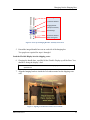
Figure 13. Eye Bolt Load Points for a Ceiling Installation............................................... 22
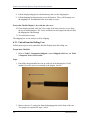
Figure 14. Close-up of Eye Bolt Assembly ...................................................................... 22
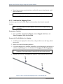
Figure 15. Hanging Bracket Load Points for a Wall Installation ..................................... 23
Figure 16. Close-up of Hanging Bracket Assembly Front View ...................................... 23
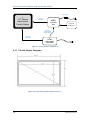
Figure 17: Overall System Configuration ......................................................................... 28
Figure 18: NanoLumens Flexible Display Front View..................................................... 28
Figure 19: NanoLumens Flexible Display Back View ..................................................... 29
Figure 20: NanoLumens Power Supply Front View......................................................... 30
Figure 21: NanoLumens Power Supply Rear View .......................................................... 31
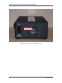
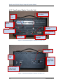
Figure 22: NanoLumens Display Controller Unit Front View ......................................... 32
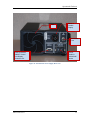
Figure 23: NanoLumens Display Controller Unit Rear View .......................................... 32
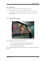
Figure 24: NanoLumens Flexible Display Hung from Ceiling ........................................ 33
Figure 25: Flexible Display Cable Connections ............................................................... 34
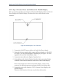
Figure 26: Basic Display Controller Unit Setup Configuration........................................ 35
Figure 27: Power Supply ON/OFF Configuration ............................................................ 38
Figure 28: Remote Management Configuration (for NanoLumens Personnel Only)....... 38
Figure 29: Flexible Display Status LEDs ......................................................................... 40
Tables
Table 1. Flexible Display Shipped Components................................................................. 7
Table 2. Required Tools Not Provided ............................................................................... 9
Table 3. Flexible Display Mounting Options ................................................................... 17
Table 4. Configuration Button Descriptions ..................................................................... 36
Table 5. Flexible Display Troubleshooting Colors ........................................................... 37
Table 6. Flexible Display Monitor Status LEDs ............................................................... 40
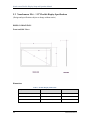
Table 7. Flexible Display Dimensions .............................................................................. 46
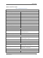
Table 8. Flexible Display Specifications .......................................................................... 47
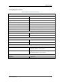
Table 9. Display Controller Specifications ....................................................................... 49
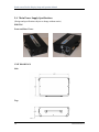
Table 10. Main Power Supply Specifications ................................................................... 51
DMAN-0001 REV B
v