1
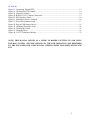
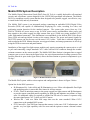
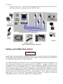
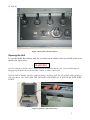
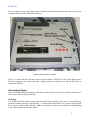
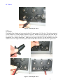
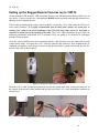
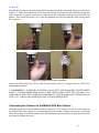
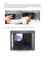
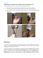
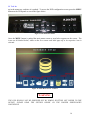
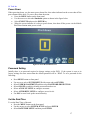
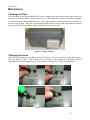
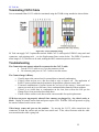
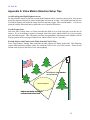
S4 Tech Inc
MOBILE DIGITAL OBSERVATION
GUARD (DOG) USER MANUAL
Version 1.0
Feb. 1, 2010
0
S4 Tech Inc
Table of Contents
Mobile DOG System Description............................................................................................................. 3
Setting up the Mobile Base Station .......................................................................................................... 4
Opening the Unit................................................................................................................................... 5
Connecting Power ................................................................................................................................. 6
AC Power.......................................................................................................................................... 6
DC Power.......................................................................................................................................... 7
Powering Up the Mobile DOG ............................................................................................................. 8
Setting up the Rugged Remote Cameras (up to 1500 ft) ........................................................................ 10
Connecting the Cameras to the Mobile DOG Base Station ................................................................ 11
Using the External PTZ Joystick ........................................................................................................ 13
Alignment of Cameras ........................................................................................................................ 14
Removing a connection from a Remote Camera Unit (Figure 17) ..................................................... 15
DVR Setup .............................................................................................................................................. 15
Power Down ....................................................................................................................................... 17
Password Setting................................................................................................................................. 17
Set the Date/Time ............................................................................................................................... 17
Set Recording Mode ........................................................................................................................... 18
Configure Motion Detection, Video Loss, and Alarms ...................................................................... 18
Exporting Video Clips to CD ............................................................................................................. 19
Changing/Focusing a Lens ..................................................................................................................... 20
Maintenance............................................................................................................................................ 21
Cleaning the Filters ............................................................................................................................. 21
Changing the Fuses ............................................................................................................................. 21
Terminating CAT-5 Cable ...................................................................................................................... 22
Troubleshooting ...................................................................................................................................... 22
Contact Info ............................................................................................................................................ 24
Replacement Parts .................................................................................................................................. 24
Appendix A: Video Motion Detection Setup Tips ................................................................................. 25
Table of Figures
Figure 1: Mobile DOG Base Station ........................................................................................................ 3
Figure 2: Mobile DOG System and Options ............................................................................................ 4
Figure 3: Rear panel of the Base Station. ................................................................................................. 5
Figure 4 Open Case and Caution Area. ................................................................................................... 5
Figure 5: The Front or User Panel. ........................................................................................................... 6
Figure 6: Connecting AC Power............................................................................................................... 7
Figure 7: Connecting DC Power............................................................................................................... 7
Figure 8: Power on the Unit...................................................................................................................... 8
Figure 9: Turn off the Battery Alarm. ...................................................................................................... 8
Figure 10: Powered Up Monitor View. .................................................................................................... 9
Figure 11: Prep CAT-5 for Camera Connection..................................................................................... 10
Figure 12: CAT-5 Cable through Watertight Connector Body .............................................................. 10
Figure 13: Complete CAT-5 Camera Connection .................................................................................. 11
Figure 14: Connect Camera to Base Station. .......................................................................................... 12
Figure 15: Live Camera Image on Monitor. ........................................................................................... 12
Figure 16: External PTZ Joystick. .......................................................................................................... 13
1
S4 Tech Inc
Figure 17: Connecting External PTZ...................................................................................................... 13
Figure 18: Checking the PTZ Channel. .................................................................................................. 14
Figure 19: Aligning a Camera. ............................................................................................................... 14
Figure 20: Remove CAT-5 Camera Connection .................................................................................... 15
Figure 22: DVR Interface Panel. ............................................................................................................ 16
Figure 21: Main Menu Screen - Labeled. ............................................................................................... 16
Figure 23: Power Down Menu Screen.................................................................................................... 17
Figure 24: Plug in USB Storage Device. ................................................................................................ 19
Figure 25: Changing//Focusing a Lens ................................................................................................... 20
Figure 26: Cleaning the Filters. .............................................................................................................. 21
Figure 27: Changing Fuses. .................................................................................................................... 21
Figure 28: CAT-5 Termination Wiring .................................................................................................. 22
NOTE: THIS MANUAL SERVES AS A GUIDE TO RAPIDLY SETTING UP AND USING
THE DOG SYSTEM. SPECIFIC DETAILS OF THE DVR OPERATION ARE DEFERRED
TO THE ENCLOSED DVR USER MANUAL WHICH COMES PACKAGED WITH EACH
KIT.
2
S4 Tech Inc
Mobile DOG System Description
The Mobile Digital Observation Guard (DOG) from S4 Tech is a rapidly deployable self-contained
security and surveillance system designed for the CENTCOM operational environment. The Mobile
DOG is a standalone security system that has been designed to be portable, rugged, cost effective, easy
to install in the field, and easy to maintain.
The Mobile DOG system is an integrated package containing an embedded H.264 Digital Video
Recorder (DVR) unit capable of simultaneously displaying live video, recording live video, and
performing motion detection for the attached cameras. The system takes power from any 110240VAC 50/60Hz AC power source or any 10-30 DC power source, and distributes video, power, and
data signals to the remote rugged low-light camera units up to 1500ft away using standard CAT-5
cable with standard connectors. This distribution is accomplished via the built-in DOG Video Power
Data (VPD) unit and specialized circuitry at the remote cameras. The power and control signals for
DOG PTZ cameras can also be sent over the same CAT-5 cables. Video data is collected, displayed,
and recorded at the DVR. Motion detection, user triggered alarms, and storage parameters are all set up
using the DVR screen menus and panel buttons.
Installation of the rugged low-light camera modules only requires mounting the camera unit to a wall
or pole and connecting a single standard CAT-5 cable with an RJ-45 connector through the weather
resistant connector on the camera module. The Mobile DOG Base Station is integrated into a rugged
transport case as seen is shown in the figure below. An active thermostat based cooling system (as seen
from the filtered air ports in the figure below) allows the Base Station to operate in temperatures up to
50 deg C.
Figure 1: Mobile DOG Base Station
The Mobile DOG system with its various options and configurations is shown in Figure 2 below.
Option kits for the DOG system are:
• IR Illuminator Kit - both visible and IR illumination to over 300m with adjustable flood light
and spotlight modes via removable filter lenses for all four cameras.
• PT Kit – Pan/Tilt units that connect to the remote rugged low-light cameras and IR illuminators
to provide remote controlled pan/tilt capability for both day and nighttime surveillance of large
areas. No additional cables are required to add the Pan/Tilt unit to a camera. It operates using
the same signal/power CAT-5 cable as a DOG Camera.
• Wireless Kit – with over 200m LOS range that uses the same standard 1500m CAT-5
connections as the standard DOG system.
• PTZ Camera Kit – Pan/Tilt/Zoom cameras that connect via the same CAT-5 infrastructure, and
provide very low light capability with 10x zoom and the option to mount a thermal camera
also.
3
S4 Tech Inc
•
Thermal Camera Kit – small form factor thermal cameras that run off the DOG CAT-5
infrastructure and can be integrated with the DOG PTZ unit.
Figure 2: Mobile DOG System and Options
Setting up the Mobile Base Station
WARNING
MAKE SURE THE MONITOR IS POWERED DOWN IF YOU ARE PLANNING ON OPERATING
THE MOBILE DOG BASE STATION WITH THE LID CLOSED. FAILURE TO DO SO MAY RESULT
IN TEMPERATURE DAMAGE TO THE MONITOR.
The connection panel on the back of the case as seen in the figure below is the main interface for all
power and camera connections. The connectors labeled “CAMERA 1” through “CAMERA 4” are
covered RJ-45 jacks used with the DOG’s CAT-5 cable infrastructure. The BNC connector labeled
“VIDEO OUT” is used with standard 75ohm coax cable to send the Mobile Base Station video to any
NTSC compatible monitor. The AC input is a standard IEC receptacle labeled “110-240VAC” and can
take any AC input within that range at 50 or 60 Hz. The DC input is labeled “12-24VDC” and uses the
special interface cable provided in the cable bin as discussed below. The DC input will tolerate an
input range of 10 to 30 volts DC. The connector labeled “Ethernet” is an RJ-45 jack used for
connecting the DOG to a LAN or the WEB for networking applications.
4
S4 Tech Inc
Figure 3: Rear panel of the Base Station.
Opening the Unit
To open the Mobile Base Station, undo the two latches on the outside of the case and lift up the lid as
shown in the figure below.
WARNING
As seen in the figure below, there is a gap between the open lid and the case. Do not stick fingers in
this gap to pick up the unit or for any other reason, as injury could result.
With the built in monitor the lid is relatively heavy, so please close the lid carefully while guiding it
with your hand. DO NOT PUSH THE LID DOWN UNGUIDED AS IT WILL SLAM WITH SOME
FORCE.
Figure 4 Open Case and Caution Area.
5
S4 Tech Inc
The user panel as seen in the figure below contains all the buttons and interfaces necessary for the
complete operation of the Mobile Base Station.
Figure 5: The Front or User Panel.
There is a small cable bin built into the user panel marked “CABLES” as seen in the figure above.
This bin contains power cables and fuses. Simply unscrew the finger-screw and lift the lid up to
expose the cable bin.
Connecting Power
Place the Mobile DOG Base Station on the table or desk where it is to be used. Connect either the AC
or DC power cable as described below.
AC Power
The Mobile DOG has built in surge protection and battery backup, so the use of an external surge
protector or battery backup is not necessary. To connect the mobile DOG to AC power simply remove
the AC power cord from the cable bin. Make sure the power switch is in the off position and then plug
in the cable as shown in the figure below.
6
S4 Tech Inc
Figure 6: Connecting AC Power
DC Power
The Mobile Base Station can be powered with a DC input range of 10-30 volts. This allows standard
12VDC batteries or 24VDC military batteries to be used. Remove the DC cable from the cable bin on
the user panel. Connect the back end to your DC source using terminal blocks, adapters, or other
appropriate low voltage connections. Make sure the power switch is off and attach the front end
connector to the DC input on the back panel of the Mobile Base Station as shown in the figure below.
Figure 7: Connecting DC Power
7
S4 Tech Inc
Powering Up the Mobile DOG
To power up the mobile dog after the power source is connected, simply flip on the power switch as
shown in the figure below.
Figure 8: Power on the Unit.
There is a battery alarm to indicate that the mobile dog has lost power and is running on the backup
battery. The battery may last from 5 to 20 minutes depending on charge state and conditions, and is
simply meant to allow for a smooth power down.
WARNING
DO NOT RUN THE MOBILE DOG WHILE ON BATTERY BACKUP, AS THE BATTERY CAN DRAIN
AND RESULT IN AN UNSAFE POWER DOWN OF THE UNIT. WHEN POWER IS LOST AND THE
BATTERY MODE KICKS ON, EXECUTE A PROPER POWER DOWN PROCEDURE.
To disable the audible battery alarm flip the switch as shown in the figure below.
Figure 9: Turn off the Battery Alarm.
8
S4 Tech Inc
Once the unit powers up and finishes booting, a blank quad channel display will show on the screen as
seen in the picture below.
Figure 10: Powered Up Monitor View.
9
S4 Tech Inc
Setting up the Rugged Remote Cameras (up to 1500 ft)
At this point the DVR, monitor, VPD, and alarm box are setup and the monitor shows a blank view as
seen above. If this is not the view, then push the MODE button repeatedly until the split channel view
showing all four channels is seen.
The first step in setting up the remote camera modules is to run the CAT-5 cables from the VPD out to
each camera location. It is highly recommended that all cables and cameras are tested prior to
running your cables to the final installation point. This will help reduce work if a bad cable or
connector is found prior to the running of the cable. The CAT-5 cables should not exceed 1500ft for
optimum performance and should be UV resistant if they are going to be outdoors for prolonged
periods of time (months).
Once the camera modules have been mounted and the cable has been run, the connection at each
camera end is made. First prep the CAT-5 cable by removing any protective boots around the RJ-45
connector and adding several wraps of electrical tape (to help ensure a good seal) around the first few
inches of the cable as shown below.
Figure 11: Prep CAT-5 for Camera Connection
Once the CAT-5 cable end has been prepared, unscrew the bottom half of the waterproof connector on
the bottom of the remote camera module and pass the end of the CAT-5 cable through the connector as
shown below.
Figure 12: CAT-5 Cable through Watertight Connector Body
10
S4 Tech Inc
Plug the RJ-45 connector into the female RJ-45 receptacle inside the waterproof connector as shown in
Figure 15. Make sure that the RJ-45 tab lines up with the connector tab hole and that it snaps into
place inside the receptacle. Once this is done, screw the watertight connector cover back on and
tighten. Then strain relieve the CAT-5 cable by tightening the lower nut until the cable is snug inside
the connector.
Figure 13: Complete CAT-5 Camera Connection
Back at the DVR station, the CAT-5 cable for that camera can now be plugged into the VPD in the
corresponding channel.
*** WARNING*** IN ORDER TO PREVENT CAPACITIVE OVERLOADING OF THE POWER
SUPPLY, IT IS RECOMMENDED TO PLUG THE VIDEO CABLES INTO THE VPD ONE AT A
TIME WHILE THE VPD IS ALREADY POWERED UP. THIS IS ESPECIALLY IMPORTANT IF
THE CAT-5 CABLES ARE SHORTER THAN A FEW HUNDRED FEET.
Connecting the Cameras to the Mobile DOG Base Station
Once the cameras have been connected to their respective CAT-5 cables, it is time to connect them to
the Mobile DOG Base Station. It is recommended to have the Base Station powered up as described
above and to plug each camera one at a time; this eliminates any potential power surge associated with
powering everything up at once.
11
S4 Tech Inc
To connect the camera first identify the channel connector on the back panel of the Base Station that
you would like to connect the given camera to. Then unscrew the connector cover to expose the RJ-45
receptacle underneath as shown in the figure below. Take the RJ-45 connector at the other end of the
CAT-5 camera cable and plug it in as shown in the figure below.
Figure 14: Connect Camera to Base Station.
Once inserted you should see the live video on the monitor as seen in the figure below.
Figure 15: Live Camera Image on Monitor.
12
S4 Tech Inc
Using the External PTZ Joystick
The Mobile DOG Base Station supports an external Pelco-D Joystick option as seen in the figure
below.
Figure 16: External PTZ Joystick.
To use the external joystick in place of the DVR panel buttons for PTZ camera control, remove the
CAT-5 jumper from the joystick ports on the front panel as seen in the figure below. Next plug the RJ45 cable from the joystick into the Joystick PTZ port as shown. The external joystick is now ready for
use with the Mobile DOG Base Station.
Figure 17: Connecting External PTZ
Set the channel on the joystick by typing the channel number (01, 02, 03, 04) and then push the CAM
button to set it in memory. This must be done every time the system is powered up. Make sure that
channel you set matches the channel setting on the back of the connected DOG PTZ camera as seen in
the figure below.
13
S4 Tech Inc
Figure 18: Checking the PTZ Channel.
Once the channel is set properly and matches the camera channel on the Base Station and the channel
sticker on the back of the PTZ unit, the joystick will pan and tilt the camera. The Mobile DOG Base
Station does not currently support diagonal movements, so pointing the joystick in a diagonal direction
will cause either a pan or tilt to occur – whichever motion is received first. Twist the joystick
clockwise to zoom in and counterclockwise to zoom out. The NEAR and FAR buttons on the joystick
will focus the PTZ camera. If a DOG thermal camera is mounted to the PTZ unit then the OPEN and
CLOSE buttons on the joystick will toggle the video display between the two cameras.
Alignment of Cameras
Camera alignment is accomplished by having a person at the camera loosen the thumb screw (as seen
in the first image of the figure below) on the tripod and move the camera around while a person
viewing the camera on the monitor communicates alignment instructions. If you have the optional
BNC viewing port and field monitor connect it up as seen in the second and third images. Once the
camera is aligned properly lock it down with the thumbscrew as seen in the first image.
Figure 19: Aligning a Camera.
14
S4 Tech Inc
Removing a connection from a Remote Camera Unit (Figure 17)
To remove the connection from a remote camera unit perform the following:
•
•
•
Loosen the lower waterproof connector nut until the cable is loose in the connector
Loosen the lower portion of the waterproof connector and remove from the main body
Put a screwdriver into the main body and push the RJ-45 tab up while simultaneously pulling
out the cord
Figure 20: Remove CAT-5 Camera Connection
DVR Setup
The DVR has been pre-configured at S4 for immediate operation. After the Mobile DOG system is set
up, the user may read through the DVR manual and configure the system as desired. Some important
configuration information is provided below.
The DVR is configured via menu items that are presented by pressing the MENU button on the DVR
panel and using various other panel buttons to make selections. To select an item use the up and down
arrows to scroll the cursor to the item and then push the ENTER. Once the item is highlighted use the
up/down arrows to select a new value for the item. Once the proper value is displayed, push the
ENTER button to select the new value and finalize the change. The ESC button takes you one layer
15
S4 Tech Inc
up in the menu tree each time it is pushed. To access the DVR configuration screen, press the MENU
button on the DVR panel as seen in the figure below.
Figure 21: DVR Interface Panel.
Once the MENU button is pushed the main menu screen as seen below appears on the screen. The
icons are all labeled below, while on the live screen each label pops up as its respective icon is
selected.
Figure 22: Main Menu Screen - Labeled.
WARNING
THE DVR SHOULD NOT BE POWERED OFF BY SIMPLY SHUTTING OFF POWER TO THE
DEVICE. PLEASE READ THE SECTION BELOW ON THE PROPER POWER-DOWN
PROCEDURE.
16
S4 Tech Inc
Power Down
When powering down, use the menu power down first, then when indicated on the screen shut off the
power button on the back. To power down from the menu:
• Press the MENU button on the front panel
• Use the arrows to select the Shutdown option as shown in the figure below
• Select EXECUTE and press the ENTER key
• When the screen indicates it is okay to power down, then shut off the power via the Mobile
DOG Base Station main power switch.
Figure 23: Power Down Menu Screen.
Password Setting
Initially there is no password required to change settings on the DVR. If the system is reset to its
factory settings for some reason then the default password will be “1234”. To set a password do the
following:
•
•
•
•
•
•
•
Press MENU button on front panel
Use arrows to select SYSTEM SETUP with cursor and push ENTER
Select USER MANAGEMENT and then select PASSWORD PROTECTION
Select ON/OFF to enable or disable password based access.
Select ACCOUNT SETUP to configure accounts.
Select AUTHORITY SETUP to configure access levels.
Use ESC to move back up the menu hierarchy.
Set the Date/Time
To set the Date/Time of the unit:
• Press the MENU button on the front panel
• Use the arrows to select SYSTEM SETUP and press ENTER
• Select DATE/TIME SETUP and then press ENTER
17
S4 Tech Inc
•
•
Select and assign the various parameters using the LEFT and RIGHT ARROWS to choose
options and the UP and DOWN ARROWS to change values.
Use ESC to move back up the menu hierarchy
Set Recording Mode
The recording mode is used to set resolution and preset configuration. The recommended option that
gives a good mix of resolution and frames/sec for 4 cameras is 720 X 240 @ 60PPS. The default and
recommended mode is Event Based which means that only motion detection and user triggered events
will be stored.
***WARNING***
IN ORDER TO CHANGE THE RECORD MODE ALL EXISTING
RECORDED CLIPS WILL BE PURGED SO MAKE SURE THAT ALL DESIRED VIDEO CLIP
DATA HAS BEEN TRANSFERRED TO CD’S IF YOU HAVE ALREADY RECORDED VIDEO
AND PLAN TO CHANGE THE RESOLUTION.
To reset the recording mode to the recommended settings use the following steps:
•
•
•
•
•
•
•
•
Press the MENU button on the front panel
Use the arrows to select RECORD SETUP and press ENTER
Select RECORD MODE and then press ENTER
Select 720X240 @60PPS and press ENTER
Press ESC to go back up to RECORD MODE menu
Select PRESET CONFIG and press ENTER
Select EVENT ONLY and press ENTER
Use ESC to move back up the menu hierarchy
Configure Motion Detection, Video Loss, and Alarms
The Event menu is where alarms are configured. If there is a loss-of-video alarm, motion detection
alarm, or input alarm triggered by the Alarm Button Box, then recording to the hard drive of the event
begins automatically. These alarms can be turned off during system setup as they can be annoying.
Once the system is setup the following alarm settings are recommended for normal use:
•
•
•
•
•
•
•
•
•
•
•
•
Press the MENU button on the front panel
Use the up/down arrows to select EVENT SETUP and press ENTER
Select INTERNAL BUZZER and select ON/OFF to set the audio alarms.
Select PER CHANNEL CONFIG and then press ENTER
Select CHANNEL SELECT and press ENTER
Select CH1 and press ENTER
Select VIDEO LOSS DETECT and press ENTER
Select ON and press ENTER to detect loss of video input.
Select MOTION DETECT and press ENTER
Select ON and press ENTER
Select DETECTION CONFIG and press ENTER
Select DETECTED AREA SETUP and press ENTER
18
S4 Tech Inc
•
•
•
•
•
•
•
Use the up/down arrows and the ENTER key to create a detection area profile on the screen.
Anything outside the defined area will not be detected.
Press ESC to go up one menu layer
Select SENSITIVITY and press ENTER
Use the up/down arrows to select a value that is suitable (88% is a good start)
Select BLOCK THRESHOLD and press ENTER. This value represents the percentage of the
screen area that a detected object must occupy before an alarm is declared.
Select an appropriate value (3-5% is a good start) and press ZOOM/ENTER
Repeat this process for channels 2-4
Exporting Video Clips to CD
Video clips may be exported to a USB storage device via the USB port on the front panel. If the
selected clips occupy more memory space than is available on the USB storage device then the backup
will be rejected and the process must be started over – so be conservative in selecting the number of
clips to be backed up. The figure below shows a USB stick and USB hard drive connected to the USB
port on the front panel. A USB CD/DVD burner with a standard device driver (does not require any
device driver software to operate) may also be used.
Figure 24: Plug in USB Storage Device.
To export clips to the installed USB storage media do the following:
•
•
•
•
•
•
•
Insert USB recording media (stick, harddrive, or CD/DVD burner) into USB port on front panel
Press the SEARCH button on the DVR panel
Select the SEARCH EVENTS option and then select a clip and start playing it back.
Press the COPY key and it will mark the start of the export.
When the playback has reached the point that you want to stop then:
Press the COPY key again and it will mark the stop the export.
Follow the screen menus to burn the selected export to USB media.
19
S4 Tech Inc
Changing/Focusing a Lens
The remote camera units are supplied with 3mm or 6mm lenses installed as indicated on the bottom of
each remote camera box. Additional 3mm and 12mm replacement lenses have been provided to
change the field of view and distance of two cameras as needed. The 3mm lens will provide a wider
field of view while the 12mm lens will provide a narrower field of view for longer range.
To change a lens the camera must be plugged in near the DVR so that the image may be focused while
the new lens is installed. With a short CAT-5 cable, plug the camera into the VPD near the DOG Base
Station so that the monitor is visible. Select the channel that the camera is plugged into by pressing the
corresponding number button on the DVR. This will put the camera view in full screen mode.
Unscrew the end cap on the camera as shown in the figures below. Be careful not to tip the cap when
removed as there are some small parts that may fall out. Once the cap is removed, locate the set screw
in the rim of the camera body and use a very small screwdriver (supplied with DOG Kit) to loosen it
slightly. Now unscrew the lens by fingertip until it comes out.
Screw in the replacement lens and turn it until the picture on monitor is in focus. Once in its best focus
position, tighten the lens down by turning the set screw with the small screwdriver. Screw the cap
back on by fingertip.
Figure 25: Changing//Focusing a Lens
20
S4 Tech Inc
Maintenance
Cleaning the Filters
The white filter covers for the Mobile DOG active cooling system can be seen on the sides of the case
as shown in the figure below. Inside each cover is a filter element that can be removed by pulling it
out from the opening underneath each cover. Once removed, rinse each filter with water and allow to
air dry for a few hours. Once dry, re-insert the filter into the filter cover; in the compartment closest to
the case wall. The filter should be right up against the transport case wall.
Figure 26: Cleaning the Filters.
Changing the Fuses
If the system does not power up then a fuse may be blown. There are two fuses on the front panel, a
20A fuse and a 2A fuse. The 20 amp fuse is removed by unscrewing the fuse holder with the
fingertips as shown in the figure below. A screwdriver is used on the 2A fuse as shown below.
Figure 27: Changing Fuses.
21
S4 Tech Inc
Terminating CAT-5 Cable
It is recommended that CAT-5 cables be terminated using the T568B wiring standard as shown below.
Figure 28: CAT-5 Termination Wiring
S4 Tech can supply CAT-5 options that include 1000ft CAT-5e cable spools, EZRJ-45 crimp tools and
connectors, and stripping tools – see the Replacement Parts section below. The EZRJ-45 products
allow longer (2-4”) lead wires to be used, making the RJ45 connection process much easier.
Troubleshooting
The Camera does not operate when first connected to the CAT-5 cable:
• Test the CAT-5 cable to see if it or the connector is bad
• Use a known good piece of CAT-5 cable to test the camera.
The Camera Image is Blurry.
• Visually inspect the camera lens for external dust or internal condensation.
• If there is dust on lens, use a lint free cloth or wipe to clean it off. The application of
RAIN-X water repellant may help minimize frequent dust collection on the lens.
• If internal condensation is present loosen the end cap of the camera 5 turns and leave
camera powered on for several hours. Once condensation has burned off then retighten.
• If there is no visible dust or condensation on the lens, then refocus the lens per the
Change/Focus Lens procedure described above.
• If none of these actions work, then send in camera module for repair/replacement
VPD does not power up properly when all four cameras are plugged in – the video is noisy or
black. Unplug all remote camera units and power up the VPD. With the VPD still powered on, plug
the remote cameras back in one at a time.
Video image comes and goes on the monitor. Try moving the CAT-5 cable around near the
connectors on both the camera end and the base station end. If the video fluctuates with the cable
movement then the cable is going bad.
22
S4 Tech Inc
I get motion alarms for no reason every 15 to 30 seconds. It has been observed on some DOG
DVR’s that having a Sequence Call Monitor Schedule enabled can cause false motion detection events.
To remedy this problem the following procedure should be followed:
•
•
•
•
•
•
•
Press the MENU button on the front panel
Use the up/down arrows to select SEQUENCE SETUP and press ZOOM/ENTER
Use the up/down arrows to select CALL MONITOR DWELL and then press
ZOOM/ENTER
Use the up/down arrows to select 120Sec and press ZOOM/ENTER
Use the up/down arrows to select CALL MONITOR SCHEDULE and press
ZOOM/ENTER
Use left arrow to delete all channels and press ZOOM/ENTER
Press ESC, ESC
When searching for an alarm clip the unit freezes up and the buttons on the front panel do not
respond. Sometimes a recorded event clip can be corrupted and it will cause the DVR to freeze up
when it enters the search window. The only current solution to this problem is to purge all the
recorded data. If there are important event clips on the DVR that are not on the same search screen as
the corrupted clip, then search them and burn them to a CD or USB stick. Then purge all data and start
over again.
•
•
•
Press the MENU button on the front panel
Use the up/down arrows to select RECORD SETUP and press ZOOM/ENTER
Select the PURGE DATA option and select ZOOM/ENTER
Some of the buttons on the front panel including the MENU button, do not respond when
pressed and there is a key shaped icon “
” near the bottom of the screen. This indicates that
the front panel has been locked. To unlock the front panel simply press and hold down the ESC button
on the front panel until the icon disappears from the bottom of the screen.
The camera images are dark even though it is not very dark outside. Turn up the brightness on the
monitor for each affected camera until the picture improves. If the picture does not improve up to the
point that the image washes out, then it is too dark and some illumination is necessary.
• Press the MENU button on the front panel
• Select CAMERA SETUP select CHANNEL press ZOOM/ENTER to change
• use the UP/DOWN arrows to select the desired channel and then ZOOM/ENTER to set
• Select BRIGHTNESS, then ZOOM/ENTER then use the UP/DOWN arrows to adjust.
• Select ZOOM/ENTER to set new level and ESC repeatedly to exit the menus.
Some of the CAT-5 connectors on the Remote Camera Modules seem to be corroding. Make sure
the seal around the CAT-5 cable coming into the Remote Module is tight. Wrap tape around the cable
before tightening the connector if necessary to get a tight seal. If available, consider applying a
silicone based dielectric grease to the contacts for extra corrosion protection.
23
S4 Tech Inc
Contact Info
For questions or support please see our website at: www.s4-tech.com or contact:
[email protected], 703-467-9034
For user manual or other technical downloads go to the customer tab on the website and login with the
following: user: customer password: 2004-S4Tech
Replacement Parts
The following replacement parts may be ordered for the DOG Base Kit (prices do not include
shipping). Credit card orders are accepted. Please contact S4 Tech for order information.
Part No.
DB-RC-xxx
DB-C5S-1000
DB-EZ-TS
DB-LPCC
DB-VPC-100
Description
Cost USD
Rugged Remote Camera Module (xxx – 3mm, 6mm, 12mm)
400.00
CAT-5e Cable 1000ft spool (outdoor grade)
240.00
CAT-5 EZRJ-45 termination set (tools & 50 connectors)
160.00
Low profile color camera.
200.00
Video Power Cable (100ft) for low profile color camera
150.00
* Prices are as of Aug. 1, 2008 and are subject to change based on availability and material costs.
24
S4 Tech Inc
Appendix A: Video Motion Detection Setup Tips
Avoid Looking into High Brightness Areas
Do not point the camera at the sun or towards the locations where sunrise or sunset occur. Also do not
point the cameras at directly at where bright lights will turn on at night. The bright light from the sun
or artificial lighting will make the image wash out and may trigger video motion alarms. It is best to
point the camera downward and to capture the area of interest from above.
Use the Proper Lens
Select the lens (3.6mm, 6mm, or 12mm) such that the field of view of the lens just covers the area of
interest. If you are looking at a gate for example, then select a lens whose field of view just covers the
gate and entrance path. This will greatly increase your probability of detection as the intruder will fill
a larger portion of the viewing area than a lens whose field of view is a lot wider.
Exclude Objects that Flutter in the Wind from the Field of View
Trees, flags, banners, laundry lines, and other movable objects will flutter in the wind. This fluttering
causes motion detection alarms if they are within the field of view of a DOG camera. Please do not
include such objects in the field of view when sighting.
Lens field of view matches
area of interest
Area of Interest
Objects that flutter in wind are
excluded from field of view
25