1
Enable-IT 868 Pro
Rev B Single Pair PoE+
Ethernet Extender
Quickstart Guide
All Rights Reserved 1997 -2014 ENABLE-IT - Proprietary and Confidential
INSTALLING THE 868 PRO SINGLE PAIR POE+ KIT
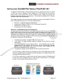
The Enable-IT 868 Pro PoE+ & Extended Ethernet Kit have a distance restriction of 1,000ft
or 305m over 1-pair of Category 3 up to Category 5e / CAT6 wiring from your LAN and
power source to the remote PoE+ device. Therefore quick, simple site surveys and
installation planning are highly recommended – This is ideal for installing PoE+ IP Security
cameras or PoE+ WiFi Access Points.
This chapter describes the recommended installation process for the Enable-IT 868 Pro
PoE+ & Extended Ethernet Kit. It covers the following topics:
Site Plan – Installation Design Considerations
Unpacking the Enable-IT 868 Pro PoE+ & Extended Ethernet Kit
Perform an out of the box Test
Performing the On-Site Installation
Site Plan - Installation Design Considerations
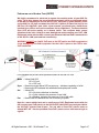
The planning process should involve a site walkthrough and discovery survey. Electrical
Cable measurement tools are the most reliable method to determine the longest run of
hidden wiring. Estimate the best locations to position the Broadband Concentrators to
adequately reach desired connectivity on each floor. Document your findings to use in
designing a network topology to support the Ethernet Switches and backbone connectivity.
Key points to remember in the Site Survey.
Total distance limitation of 1,000ft / 305m from end to end. 1-pair Cat5e .30 Gage or better cabling is required for the 868 Pro Interlink
transmission.
Cisco PoE+ single line injector support built in. Not compatible with any PoE+
switches as the PoE+ switches are not smart enough to understand Extender
Ethernet timing mechanisms and fail to set correct output voltage and will
subsequently disable the PoE+ switch port.
Transparent to single line 802.3af/802.3at PoE+ injectors and devices.
For CAT3 wiring (1-pair/2 wires) you will need to crimp a RJ-45 Male Head to each
end of the contiguous wire run and using the following pins (1,2) straight through. This
will deliver Ethernet Data and PoE+.
For CAT5e or better wiring (1-pair/2 wires) you will need to crimp a RJ-45 Male Head
to each end of the contiguous wire run and using the following pins (1,2) straight
through. This will deliver Ethernet Data and PoE+.
868 Pro CO
All Rights Reserved 1997 - 2014 Enable-IT, Inc.
868 Pro CPE
Page 2 of 7
Perform an out of the box Test (OOTBT)
We highly recommend a quick test to ensure the working order of your 868 Pro
units. To do this, please use one of the Ethernet patch cords provided and attach
to the 868 Pro Interlink port of each 868 Pro unit. Using the 5v power adapter, power
up the 868 Pro CO Unit and attach the 360 PoE+ Injector (P+Data Out port) to the
868 Pro CO LAN1/PoE+ port. After a few seconds you should see a solid Green
Interlink Sync LED on each unit to confirm a link is established. The Green Interlink
Sync LED will pulse rapidly as it detects traffic. This confirms basic proper
operation of the units. Next for a more detailed test and to confirm your PoE+ LAN
Equipment works with the 868, connect your Ethernet LAN and PoE+ remote device
to the 868 Pro LAN ports and test connectivity.
WARNING: DO NOT use LAN1/2 PoE+ port on the CPE end for non-PoE+ equipment as
it may damage any non-PoE+ equipment. Use the LAN 3-4 ports on the CPE for nonPoE+ equipment.
LED indicators will provide visual operational status of the 868 Pro units.
Mode – Yellow Solid LED
Off = CO unit
On = CPE unit
Sync – Green slow to fast flicker LED on power up – indicates negotiation of a link
– Green solid LED indicates link established and rapid pulse is traffic
Act
– Yellow LED
Off = No device attached or detected
On = Solid, indicates the presence of local LAN
On = Blinking, indicates the presence of local LAN traffic
Pwr – Green Solid LED indicates the unit is receiving 5v power
Next for a more detailed test and to confirm your PoE+ Equipment works with the
868, connect your PoE+ device to the 868 ProCPE LAN1/PoE+ port and your LAN to
the 360 PoE+ Injector Data IN port. For use with a Cisco PoE+ device such as
Aironet WiFi AP – Use the provided Cisco PoE+ patch cord or build one using it as
a guide.
All Rights Reserved 1997 - 2014 Enable-IT, Inc.
Page 3 of 7
Performing the On-Site Installation
After removing the Enable-IT 868 P r o PoE+ & Extended Ethernet Kit from the box
and performing the out of the box testing all that remains to install the unit on-site is to
mount the unit, build the interconnect wiring, add voice lines if needed and attach the
LAN device cabling with the provided Ethernet Patch cords.
Mounting the Enable-IT 868 Pro PoE+ & Extended Ethernet Units
The Enable-IT 868 Pro PoE+ & Extended Ethernet Kit is designed for quick wall
mounting. Choose a location to mount each of the Enable-IT 868’s where the
maximum distance does not exceed 3,500ft or 1,067m total between devices to be
connected. When mounting the Enable-IT 868 P r o PoE+ & Extended Ethernet Kit
it is recommended that you use the appropriate anchors for your mounting surface.
If mounting on plywood use wood screws; if mounting onto drywall or sheetrock, use
plastic drywall anchors or Velcro can also be used as the units are very lightweight.
Building the 868 Pro Interlink wiring
The most important aspect of the install is the correct wiring of the Interlink cabling. For
CAT3 wiring (1-pair/2 wires) you will need to crimp a RJ-45 Male Head to each end of
the contiguous wire run and using the following pins(1,2) straight through.
This will deliver Ethernet Data and PoE+.
For CAT5e or better wiring (1-pair/2 wires) you will need to crimp a RJ-45 Male Head to
each end of the contiguous wire run and using the following pins(1,2) straight through.
This will deliver Ethernet Data and PoE+.
Attaching cabling and devices to the Enable-IT 868 Pro Extended Ethernet Kit.
Attach your remote PoE+ device to the 868 Pro CPE unit LAN1/PoE+ port with Ethernet
patch cord provided. Attach your local LAN to the 360 PoE+ injector Data IN port. Attach
the power adapter to the 868 Pro CO unit. Attach the 360 PoE+ injector to the 868 Pro
CO LAN1/PoE+ port with Ethernet patch cord provided. The last step is to apply power
to the 360 PoE+ injector with the country power cord provided.
Your equipment should now be powered up and functioning properly.
The LED indicators will provide visual operational status of the 868 Pro units.
Mode – Yellow Solid LED
Off = CO unit
On = CPE unit
Sync – Green slow to fast flicker LED on power up – indicates negotiation of a link
– Green solid LED indicates link established and rapid pulse is traffic
Act – Yellow LED
Off = No device attached or detected
On = Solid, indicates the presence of local LAN
On = Blinking, indicates the presence of local LAN traffic
Pwr – Green Solid LED indicates the unit is receiving 5v power
For troubleshooting, first examine the backbone wiring pair and make sure you have solid
connections. The Interlink Sync LED will be lit on each 868 unit to show proper
connection and pairing. If the Interlink Sync LED Link is flashing – (Not pulsing)
All Rights Reserved 1997 - 2014 Enable-IT, Inc.
Page 4 of 7
1) Make sure your wiring is straight thorugh and not connected to any Telco
punch down blocks or as few as possible – they add interference. If your
wiring is spliced, use Telco butt clips or gel filled caps to bridge the wire into a
solid connection. A flashing Interlink Sync LED indicates the units are trying to
connect to each other and are looking to synchronize frequencies.
2) Check for a firm connection of the RJ-45 connections in each 868 Pro unit,
check any splice points in the Interlink wiring and that the 5V power adapter is
applied to the 868 Pro CO and the 360 PoE+ injector is powered on.
3) You can always perform anther out of the box test to prove out the equipment
and then focus on your interlink wiring.
Performance Settings (DIP Switch)
If you are experiencing performance issues with your Ethernet connection you may use the
following DIP switch settings to adjust your application. For DIP switch 2-4 you must toggle
both symmetrically, in other words the CO and CPE must match. If you turn DIP switch 3 Up
(Off) on the CO, then you must do so for the CPE and vice-versa.
Switch 1: CO / CPE Mode
CO Mode – Up / Off Position
CPE Mode – Down / On Position
Central Office Equipment (CO) is generally the equipment residing at the Carrier
Telephone office or the head end of a circuit. Customer Premise Equipment (CPE) is
generally the equipment residing on the customer side of a circuit. Typically you would
place the CO at the local end and the CPE at the remote end for reference only. CO’s only
communicate with CPE’s.
Switch 2: Error Correction Mode
Interleaved Error Correction Enabled – Up / Off Position – degrades performance
Fast Channel – Down / On Position (Default)
Interleaved Error Correction works better for file transfers, where the delivered data must
be error free but latency incurred by the retransmission of error packets is acceptable. Fast
channel is preferred for streaming multimedia, where an occasional dropped bit is not
noticeable or acceptable.
Switch 3: 17a (over 1,500ft) / 30a (under 1,500ft) Mode
17a Mode – Up / Off Position
30a Mode – Down / On Position (Default)
17a mode is only used for Interlink runs over 1,500ft to 6,000ft.
30a mode is only enabled for Interlink runs under 1,500ft.
Switch 4: Signal-to-noise Noise Ratio (SNR)
9dB – Up / Off Position
6dB – Down / On Position (Default)
Signal-to-noise ratio is a measurement that refers to how much noise is in the output of a
device, in relation to the signal level. If you experience issues of noise bleeding over the lines,
or high interference in your environment, it is suggested that you switch to 6dB SNR. This may
help clean up any noise bleeding over your cabling.
All Rights Reserved 1997 - 2014 Enable-IT, Inc.
Page 5 of 7
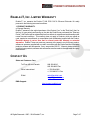
TECHNICAL SUPPORT
Enable-IT, Inc.’s Customer Care Team support is available directly to customers and
distributors. All support requests are processed through the online support portal. This allows
us to provide assigned support ticket numbers in order to bring closure to any technical issues.
Online Technical Services
The Enable-IT Support Portal is available 24/7 to open a ticket or check the status of one.
Please use this support website as your first source for help as it contains an on-line knowledge
base of articles, documentation, FAQ's and other problem-solving resources. This web-based
support resource provides the quickest solution to the most common technical support issues.
World Wide Web Site
http://support.enableit.com
Returning Products for Warranty Repair
Enable-IT, Inc. warrants to the original purchaser of the Product ("you" or the "End User") that,
for the four (4) year period commencing on the date the Product was purchased (the "Warranty
Period"), the Product will be substantially free from defects in materials and workmanship under
normal use and conditions. Electrical damage is not an item that is covered under this
warranty, extended warranties or Advanced Replacement Program (AREP).
In order to obtain an authorized RMA approval, the End User must complete the required
information online located at http://support.enableit.com. If you have questions or difficulty
completing this information you may contact the Customer Care Team at 888-309-0910
between the hours of 8:00 a.m. and 5:00 p.m. PT.
Please ship Authorized RMAs to:
Enable-IT Processing Facility
16600 Harbor Blvd, Suite I
Fountain Valley, CA 92708-1363
Returning Products for Refund
Enable-IT, Inc. offers a generous 45-Day refund on a single Ethernet Extender Kit only,
and is subject to a 15% Restocking Fee. Shipments without a valid or authorized RMA
number, or sent to our corporate Las Vegas address, can be refused and / or billed for
additional shipping.
All Rights Reserved 1997 - 2014 Enable-IT, Inc.
Page 6 of 7
ENABLE-IT, INC. LIMITED WARRANTY
Enable-IT, Inc. warrants the Enable-IT 868 PRO PoE & Ethernet Extender Kit solely
pursuant to the following terms and conditions.
1. PRODUCT WARRANTY.
a. Express Warranty.
Enable-IT warrants to the original purchaser of the Product ("you" or the "End User") that, for
the four (4) year period commencing on the date the Product was purchased (the "Warranty
Period"), the Product will be substantially free from defects in materials and workmanship under
normal use and conditions. This warranty does not apply to Products, which are resold as
used, repaired or reconditioned, or consumables (such as batteries) supplied with the Product.
Electrical damage is not an item that is covered under this warranty or extended
warranties. Enable-IT does not make any warranty with respect to any third party product,
software or accessory supplied with or used in connection with the Product and such third party
products, software and accessories, if any, are provided "AS IS." Warranty claims related to
such third party products, software and accessories must be made to the applicable third party
manufacturer.
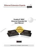
CONTACT US
Sales and Customer Care:
Toll Free US and Canada
888 309-0910
866 389-8605 Fax
Other International
+1 702 924-0402
+1 702 800-2711 Fax
E Mail
[email protected]
[email protected]
RMA Support:
http://support.enableit.com
All Rights Reserved 1997 - 2014 Enable-IT, Inc.
Page 7 of 7