1
Enable-IT 850 CPE
Ethernet Extender
Quickstart Guide
All Rights Reserved 1997 - 2014 ENABLE-IT - Proprietary and Confidential
INSTALLING THE 850 CPE ETHERNET EXTENDER
Installation
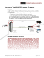
The Enable-IT 850 CPE Extended Ethernet Units have a distance restriction of 8,000ft or
2,440m over 1-pair of Category 2 up to Category 5e / CAT6 wiring from device extension
to device extension.
Total distance limitation of 8,000ft or 2,440m from end to end.
1 Pair CAT-2 wiring or 4-pair Cat5e .30 Gage or better cabling is required.
For the Interlink port use an RJ-11 connector. Crimp a RJ-11 Male Head to each
end of the contiguous wire run and using the following pins (1 & 2) straight through.
This will deliver 1 Voice line, 100Mbps Full Duplex Ethernet Data.
Perform an out of the box Test (OOTBT)
We highly recommend a quick test to ensure the working order of you 850 CPE
units. To do this, please use one of the Telephone patch cords provided and
attach to the 850 CPE Interlink port and then to the 8950 DSLAM Interlink port.
Power up both 850 CPE units and the 8950 DSLAM Concentrator. The Green Sync
LEDs will start flickering slowly and then fast as the units talk to each other. After
a few seconds you should see a solid Green Interlink Sync LED on each 850 CPE
unit to confirm a link is established. The 8950 DSLAM will take about 30 seconds
to startup then link will be established with the 850 CPE. This confirms basic
proper operation of the units. Next for a more detailed test and to confirm your
LAN Equipment works with the 850 CPE, connect your Ethernet LAN to the 8950
DSLAM and remote device to the 850 CPE LAN ports and test connectivity. The
Green Interlink Sync LED will pulse rapidly as it detects traffic.
All Rights Reserved 1997 - 2014 Enable-IT, Inc.
Page 2 of 6
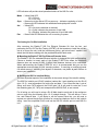
LED indicators will provide visual operational status of the 860 Pro units.
Mode – Yellow Solid LED
Off = CO unit
On = CPE unit
Sync – Green slow to fast flicker LED on power up – indicates negotiation of a link
– Green solid LED indicates link established and rapid pulse is traffic
Act
– Yellow LED
Off = No device attached or detected
On = Solid, indicates the presence of local LAN
On = Blinking, indicates the presence of local LAN traffic
Pwr – Green Solid LED indicates the unit is receiving 5v power
Performing the On-Site Installation
After removing the Enable-IT 850 Pro Ethernet Extender Kit from the box, and
performing the Out Of The Box Testing (OOTBT), all that remains to install the unit onsite is to mount the unit, build the interconnect wiring, add voice lines if needed, and
attach the LAN device cabling with the provided Ethernet Patch cords.
Mounting the Enable-IT 850 Pro Ethernet Extender Units
The Enable-IT 850 Pro extended Ethernet solution is designed for quick wall mounting.
Choose a location to mount each of the Enable-IT 850 Pro’s where the maximum
distance does not exceed 8,000ft (2,400m) total between devices to be connected.
When wall-mounting the Enable-IT 850 Pro unit it is recommended that you use the
appropriate screw anchors for your mounting surface. If mounting on existing plywood
use wood screws; if mounting onto drywall or sheetrock, use plastic drywall anchors to
secure your installation.
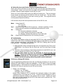
Building the 850 Pro Interlink Wiring
The most important aspect of the installation is the correct wiring of the Interlink cabling.
The 850 Pro Interlink port (RJ-45 interface) carries this 1-pair signaling over the RJ-45
(pins 1 & 2) - used as transport for both voice and data. If you use more than 1-pair of
wiring, such as a CAT5 segment, the RJ-45 (pins 3 & 4) are used for voice line 2, and
the remaining pins (4,5,7 & 8) can transport native 802.3af PoE, or are unused.
For all wiring you will need to crimp a RJ-45 Male head to each end of the contiguous
wire run and using the following (pins 1 & 2) straight through. This will deliver 1 voice
line, and Ethernet data. If you desire to use the second voice line, you will need to
request our optional dongle that will allow for connecting telephone lines to this interlink
wiring. Insert the completed RJ-45 ends into the 850 Pro Interlink port on each 860 Pro
unit.
All Rights Reserved 1997 - 2014 Enable-IT, Inc.
Page 3 of 6
Cabling Devices to the Enable-IT 850 Pro Extended Ethernet Kit
Attach your remote LAN device to the 850 Pro CPE unit LAN ports with Ethernet patch
cord provided. Attach your local LAN to the 8950 LAN ports with Ethernet patch cord
provided. Attach the power adapters to both 850 Pro units.
Attach your local Interlink cabling end to the 8950 unit Interlink port – Then do the same
for the remote end and plug into the 850 Pro CPE unit Interlink port. The Sync LED’s
will flicker in a sequence talking to each other until they go solid. Your equipment should
now be powered up and functioning.
LED indicators will provide visual operational status of the 850 Pro units.
Mode – Yellow Solid LED
Off = CO unit
On = CPE unit
Sync – Green slow to fast flicker LED on power up – indicates negotiation of a link
– Green solid LED indicates link established and rapid pulse is traffic
Act
– Yellow LED
Off = No device attached or detected
On = Solid, indicates the presence of local LAN
On = Blinking, indicates the presence of local LAN traffic
Pwr – Green Solid LED indicates the unit is receiving 5v power
Troubleshooting
First examine the backbone wiring pair and make sure you have solid connections. The
Interlink Sync LED will be lit solid Green with rapid pulsing on each 850 Pro unit to show
proper connection and pairing. If the Interlink Sync LED Link is flashing slow to fast and
never goes solid…. Then follow the steps below:
1) Make sure your wiring is straight through and not connected to any Telco punch
down blocks; If so remove from the block and use Telco butt clips to bridge
wire.
2) Check for a firm connection of the RJ-45 connections in each 860 Pro unit, and
power is applied to the 850 Pro CO & CPE units.
3) You can easily isolate any issue by performing an Out Of the Box Test
(OOTBT). This test will confirm the correct working order of your Enable-IT 860
Pro Ethernet Extender Kit. This will point to a possible issue with your long
distance Interlink wiring being affected by possible outside interference.
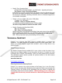
Performance Settings (DIP Switch)
If you are experiencing performance issues with your Ethernet connection you may use the
following DIP switch settings to adjust your application. For DIP switch 2-4 you must toggle
both symmetrically, in other words the CO and CPE must match. If you turn DIP switch 3 Up
(Off) on the CO, then you must do so for the CPE and vice-versa.
Switch 1: CO / CPE Mode
CO Mode – Up / Off Position
CPE Mode – Down / On Position
Central Office Equipment (CO) is generally the equipment residing at the Carrier
Telephone office or the head end of a circuit. Customer Premise Equipment (CPE) is
generally the equipment residing on the customer side of a circuit. Typically you would
place the CO at the local end and the CPE at the remote end for reference only. CO’s
only communicate with CPE’s.
All Rights Reserved 1997 - 2014 Enable-IT, Inc.
Page 4 of 6
Switch 2: Error Correction Mode
Interleaved Error Correction Enabled – Up / Off Position – degrades performance
Fast Channel – Down / On Position (Default)
Interleaved Error Correction works better for file transfers, where the delivered data must
be error free but latency incurred by the retransmission of error packets is acceptable.
Fast channel is preferred for streaming multimedia, where an occasional dropped bit is
not noticeable or acceptable.
Switch 3: 17a (over 1,500ft) / 30a (under 1,500ft) Mode
17a Mode – Up / Off Position
30a Mode – Down / On Position (Default)
17a mode is only used for Interlink runs over 1,500ft to 6,000ft.
30a mode is only enabled for Interlink runs under 1,500ft.
Switch 4: Signal-to-noise Noise Ratio (SNR)
9dB – Up / Off Position
6dB – Down / On Position (Default)
Signal-to-noise ratio is a measurement that refers to how much noise is in the output of a
device, in relation to the signal level. If you experience issues of noise bleeding over the
lines, or high interference in your environment, it is suggested that you switch to 6dB
SNR. This may help clean up any noise bleeding over your cabling.
TECHNICAL SUPPORT
Enable-IT, Inc.’s Customer Care Team support is available directly to customers and
distributors. All support requests are processed through the online support portal. This
allows us to provide assigned support ticket numbers in order to bring closure to any
technical issues.
Online Technical Services
The Enable-IT Support Portal is available 24/7 to open a ticket or check the status of one.
Please use this support website as your first source for help as it contains an on-line
knowledge base of articles, documentation, FAQ's and other problem-solving resources.
This web-based support resource provides the quickest solution to the most common
technical support issues.
World Wide Web Site
http://support.enableit.com
Returning Products for Warranty Repair
Enable-IT, Inc. warrants to the original purchaser of the Product ("you" or the "End User")
that, for the four (4) year period commencing on the date the Product was purchased (the
"Warranty Period"), the Product will be substantially free from defects in materials and
workmanship under normal use and conditions. Electrical damage is not an item that is
covered under this warranty, extended warranties or Advanced Replacement Program
(AREP).
All Rights Reserved 1997 - 2014 Enable-IT, Inc.
Page 5 of 6
In order to obtain an authorized RMA approval, the End User must complete the required
information online located at http://support.enableit.com. If you have questions or difficulty
completing this information you may contact the Customer Care Team at 888-309-0910
between the hours of 8:00 a.m. and 5:00 p.m. PT.
Please ship Authorized RMAs to:
Enable-IT Processing Facility
16600 Harbor Blvd, Suite I
Fountain Valley, CA 92708-1363
ENABLE-IT, INC. LIMITED WARRANTY
Enable-IT, Inc. warrants the Enable-IT 8950 Ethernet Extender Kit solely pursuant to the
following terms and conditions.
1. PRODUCT WARRANTY.
a. Express Warranty.
Enable-IT warrants to the original purchaser of the Product ("you" or the "End User") that, for
the four (4) year period commencing on the date the Product was purchased (the "Warranty
Period"), the Product will be substantially free from defects in materials and workmanship
under normal use and conditions. This warranty does not apply to Products, which are resold
as used, repaired or reconditioned, or consumables (such as batteries) supplied with the
Product. Electrical damage is not an item that is covered under this warranty or
extended warranties. Enable-IT does not make any warranty with respect to any third party
product, software or accessory supplied with or used in connection with the Product and such
third party products, software and accessories, if any, are provided "AS IS." Warranty claims
related to such third party products, software and accessories must be made to the
applicable third party manufacturer.
CONTACT US
Sales and Customer Care:
Toll Free US and Canada
888 309-0910
866 389-8605 Fax
Other International
+1 702 924-0402
+1 702 800-2711 Fax
E Mail
[email protected]
[email protected]
RMA Support:
http://support.enableit.com
All Rights Reserved 1997 - 2014 Enable-IT, Inc.
Page 6 of 6