1
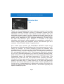
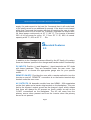
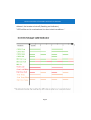
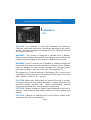
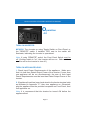
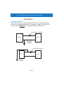
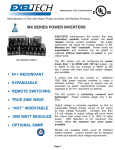
MCX/ICX INSTALLATION AND OPERATION MANUAL
MCX/ICX INSTALLATION AND OPERATION MANUAL
Copyright © 2010 Exeltech Inc. All rights reserved. This Document may not be
copied, photocopied, reproduced, translated or converted to any electronic or
machine-readable form in whole or in part without prior written approval of
Exeltech Inc.
Exeltech, Inc.
7317 Jack Newell Blvd North
Fort Worth, Texas 76118-7100
Page 1
MCX/ICX INSTALLATION AND OPERATION MANUAL
Table of Contents
Introduction 1.0
page 3
Standard Features 2.0
page 5
Installation / Operation 3.0
page 8
Appendix A
page 12
Appendix B
page 13
Appendix C
page 14
Page 2
MCX/ICX INSTALLATION AND OPERATION MANUAL
Introduction
1.0
Thank you for purchasing the finest sine-wave inverter in the power
conversion industry. Exeltech’s journey to excellence includes the first
affordable sine wave inverter, first modular inverter system, first N+1
redundant inverter system, and the cleanest sine wave output in the
industry. Exeltech strives to manufacture products of the highest possible
quality, and is dedicated to 100% customer satisfaction. Proudly built in
the USA with American parts, Exeltech is committed to TL 9000
standards and beyond, adding people and procedures continually to
further improve quality and customer service. We welcome you as a
customer to the Exeltech family. Congratulations!
.
As a stand alone inverter, the EXELTECH MCX/ICX meets all of
the power and distortion specifications that have been proven by our XP
Family of products. XP series inverters provide the cleanest, best
regulated sine wave output over the widest DC input of any inverter on
the market today. They are extremely low in Total Distortion; specified to
2%, and typically better than 1.5%. Total Harmonic Distortion is typically
0.8 to 0.9%. Remaining distortion is a result of residual switching noise,
which amounts to a very clean 25 kHz sine wave superimposed on the
fundamental output. No significant harmonics of 25 kHz exist. This
spectral purity will exist over the inverter's entire operating envelope,
including non-linear and reactive loads. As long as peak output current
remains less than 200% of rated current for XP-2000 total harmonic
distortion will remain within the 2% spec. Peak current capability of the
inverter is key to understanding it's operational envelope. As long as the
inverter is supplying less than this amount, it will function properly and
operate virtually any load.
.
Page 3
MCX/ICX INSTALLATION AND OPERATION MANUAL
The EXELTECH MCX/ICX Inverter/Charger has 1000 Watts of rated
DC power available to keep your batteries charged to their optimum
level, when power to run your critical load is available from a primary
source. However, when the primary source is interrupted, your
EXELTECH MCX/ICX stands ready to deliver 2000 Watts of rated power,
and 4000 Watts of surge power within 4mS. Then, once the primary
source of power has been restored, the Inverter/Charger will sense it’s
presence, lock on to it’s frequency, and seamlessly transfer your critical
load back to its primary source.
.
Many inverters are rated in Volt-Amps (VA), as opposed to Watts. This is
in an attempt to make an inverter or UPS (Uninterruptible Power Supply)
appear larger than it really is. The only fair way to specify these products
is in watts (W), which is power the inverter can actually deliver. If
Exeltech inverters were specified in VA, our 2000 watt inverter could be
rated at 2500 VA @ 0.8 pf., 2857 VA @ 0.7 pf, or an incredible 4000 VA
@ 0.5 pf. It is confusing to specify a product in VA, because the power
factor must also be specified. Exeltech's inverters can output their full
.
rated power continuously at 30° C (86° F)
The inverter will maintain a spectrally pure output with any load, due to a
specially designed non-linear control loop in the primary DC to DC
converter. This circuitry is one of three circuits which protect the inverter
from any overload condition.
.
EXELTECH 2KW INVERTERS
.
These inverters can supply twice their rated output power for 3 seconds,
in order to start motors or supply in-rush currents to electronic loads. If
output power is exceeded for greater than 3 seconds, output voltage is
reduced to a level which will provide the inverter’s rated power to the load
by clipping tops of the waveform. Should the overload condition clear, the
inverter will again provide the cleanest Sine Wave in the industry. If the
overload condition persists, requiring the user to cycle the power button
to turn the inverter on again. The inverter will disable its output within 7
seconds. This over-current circuitry insures maximum current does not
exceed 200% of rated RMS current for XP-2000. The third protection
mechanism is short circuit. Similar to overload condition, the inverter will
Page 4
MCX/ICX INSTALLATION AND OPERATION MANUAL
supply it’s peak current to the load for 3 seconds then it will scale back
to it’s rated current for an additional 4 seconds. If the short is not cleared
within that 7 seconds the inverter will shut off requiring the user to cycle
the power button to turn it back on. Exeltech’s inverters can output their
full rated power continuously at 30° C (86° F). The inverter is derated
20% of its full power for every 10° C over 30° C. IE; 80% of normal
.
capacity at 40° C, 60% at 50° C . . . Etc.
Standard Features
2.0
In addition to the Standard features offered by the XP family of inverters,
there are features specific to the charger and transfer switch functionality.
DC INPUTS: Positive (+) and Negative (-) input terminals are 5/6" studs
with brass hardware. They are accessed under the rear cover. Use
“Appendix A” to choose the appropriate gauge wire for your specific
.
model.
REMOTE ON/OFF: Provides the user with a remote method to turn the
inverter on and off. “REMOTE” connection is on the barrier terminal strip
.
located under the rear cover.
AC OUTPUTS: All domestic models have two NEMA - 20A receptacles
on the front plate and a barrier strip terminal on the backplane. They are
tied to the inverter’s output as well as the charger’s input, which means
that there will always be AC present on these outlets as well as the
“LOAD” connections on the backplane. The AC will come from the
primary source when present and from the inverter when the primary
.
source is not present.
Page 5
MCX/ICX INSTALLATION AND OPERATION MANUAL
EXTERNAL THERMISTOR: Supplied with unit and a required part.
It is able to sense the temperature of a battery when charging. The
“Float Voltage” will be automatically adjusted in order to avoid overcharging a hot battery.
.
BAD BATTERY PROTECTION: Will shut down the charging
function of the MCX/ICX if there is to much resistance between the
positive and negative battery connection indicating that the battery
is bad or that there is a bad connection.
.
COOLING: Provided by a thermostatically controlled brushless fan
located on the front panel.
.
DC POWER ON LED: Located on the front panel, will be "ON” when
inverter is powered up, and DC power is available.
.
LOW BATT / THERM BUZZER: Produces an audible alarm if DC
input voltage falls to a level within 2% to 4% of the low limit of
inverter, or, if there is an over temperature condition.
.
ON/OFF SWITCH: Located on front panel; turns the inverter on and
off.
.
OVER VOLTAGE PROTECTION: When the battery voltage exceeds
set limits, the inverter/charger will immediately and without warning
shut off. This will require the user to cycle the on/off switch to turn the
inverter back on. This fault can usually be attributed to a poor battery
connection or faulty battery.
.
UNDER VOLTAGE PROTECTION: When battery voltage falls to
within 5% of low line voltage, the LOW BAT/THERM buzzer will
sound. If the condition continues without reducing load to the
Inverter or adding charge to the battery, the inverter will shut off.
When voltage rises to approximately 90% of nominal battery voltage
the inverter will turn back on and the alarm condition will clear. The
inverter can be manually reset by cycling the on/off switch. This will
reset the protection circuit and turn the inverter on at any voltage
above minimum voltage.
.
Page 6
MCX/ICX INSTALLATION AND OPERATION MANUAL
OVER TEMPERATURE PROTECTION: The inverter is also
protected against overheating. It will provide its full rated output up
to the temperature listed in the specification sheet. If it is subjected
to higher ambient temperatures or air circulation is blocked, the
inverter may overheat. If the LOWBATT/THERM buzzer sounds,
immediate action is required or the inverter will shut down. Either
reduce load, or provide more cooling in the immediate environment.
If no action is taken, the inverter will likely shut down within 2
minutes. When the inverter shuts down, the alarm condition will
persist and the cooling fan will continue to run. Since the inverter
has eliminated its load, it will cool fairly quickly. It will automatically
restart when it has cooled sufficiently, and the LOW BATT/THERM
alarm will clear. “105° C internal temperature. Warning buzz 5° C
.
before shut off”.
OVERPOWER, SHORT CIRCUIT PROTECTION: The inverter has
three levels of overpower protection. The first
limits peak
instantaneous current. The second system limits absolute power
coming from the module. Both of these circuits act to reduce output
voltage as required, to limit current to a safe level. The overpower
protection circuit will recover instantly if the overpower condition
clears within 3-5 seconds. The third, is short circuit protection. If the
over current condition is so severe that it causes output voltage to
collapse for more than 5 seconds, the inverter will shut down and
not automatically restart. The LED will flash red and the fan will be
on. This requires the user to clear the short circuit safely, and
guarantee that hazardous voltage will not come back on line until
desired. To reset the inverter from this condition, cycle power switch
.
“OFF” then “ON” again.
Exeltech 2kw inverters will provide peak current (45 A at 117VAC or
22A at 230VAC) or maximum surge (4000W) for 3 seconds when
o
the inverter’s internal temperature is at or below 30 C. The output
power is then reduced to 2000W (rated power) for 4 secs. If the
inverter cannot restore a full sine wave due to overload, the LED will
be red. If the overload condition does not clear in the 7 secs.
Page 7
MCX/ICX INSTALLATION AND OPERATION MANUAL
allowed, the inverter shuts off (flashing red indicator).
* LED will be red in overload and /or short circuit conditions. *
Page 8
MCX/ICX INSTALLATION AND OPERATION MANUAL
Installation
3.0
CAUTION: It is essential to read and understand all Warnings,
Cautions, and Notes before any connections are made to the unit or
system. If further assistance is needed call (817) 595-4969 and ask
.
for Customer Service.
WARNING: The inverter is designed to operate from a Battery.
Performance cannot be guaranteed, and damage can result when a
.
charger or power supply is used without a battery in the circuit.
WARNING: The AC neutral lead is bonded to chassis through the
barrier terminal strip connector located on the back of unit. Chassis
must be bonded to earth ground through the external ground
.
connector located on the rear of the unit. (See Appendix C)
The Negative or Positive terminal of the battery (DC Source) must
be bonded to earth ground. It's recommended that it be to the same
.
earth ground used for AC ground.
CAUTION: Before any connections are made to the unit or system,
be sure to disconnect the battery terminals. Always disconnect the
grounded battery terminal first. When reconnecting, connect
.
ungrounded terminal first, and grounded terminal last.
CAUTION: Polarity of leads is critical to avoid damage to the unit or
system. Check batteries and battery cables for correct polarity and
.
voltage.
CAUTION: Observe all National and Local Electric Codes when
connecting AC Power Connections.
Page 9
MCX/ICX INSTALLATION AND OPERATION MANUAL
INSTALLATION (Location)
.
Mounting location is critical to performance and life span of the
inverter. Heat and moisture are the two worst enemies of any
electronic device. Therefore, when choosing a mounting location,
consider the following requirements listed in order of importance:
1. Inverter must be sheltered from the elements. Select a clean, dry
.
location.
2. Inverter requires adequate ventilation for cooling. With proper
cooling, the inverter will operate efficiently and meet its published
ratings. All models can be mounted in several positions. Best
position, with fan down. Second best, horizontal. Third, vertical
.
with fan up. Least preferred, upside down.
3. Inverter should be mounted as close to the battery as possible.
Shorter wire has less resistance, which translates to increased
.
efficiencies.
.
INSTALLATION (Wiring)
An in line fuse is recommended, to protect the battery and wiring to
the inverter. This fuse should be located very close to the battery
positive (+) terminal. To select appropriate size fuse, consult the
.
"Rated and Peak Current" table in appendix "A".
1. Disconnect the grounded terminal of battery and make sure the
.
charger and inverter are off.
2. Make DC input connections to the inverter as illustrated in
.
“Appendix C”.
3. (Optional) Using 12-18 AWG wire, make Remote On/Off
connection from the rear panel terminal labeled “REMOTE” to one
pole of a small toggle switch. Then from the other pole of toggle
switch, make a connection to battery negative (-).Make sure the
.
toggle switch is in the off position.
4. Reconnect grounded terminal of the battery.
Page 10
.
MCX/ICX INSTALLATION AND OPERATION MANUAL
Operation
4.0
TURN ON INVERTER:
.
MCX/ICX: Turn inverter on using Toggle Switch on Front Panel, or
the "REMOTE" switch if installed. LED next to the switch will
illuminate, indicating the inverter is operational.
.
Note: If using "REMOTE" switch, the Front Panel Switch must be
off. (If either switch is "on", the inverter will turn on. Both switches
must be off for the inverter to turn off.)
.
TURN ON APPLIANCE/LOAD:
.
1. Check Input Power Requirements of the appliance. Make sure
that it is less than Rated Output Power of the inverter. If more than
one appliance will be run simultaneously, the sum of their Input
Power Requirements must be less than Rated Output Power of the
.
inverter.
2. If Appliance/Load has been hard wired to the barrier terminal strip
as illustrated in Appendix "C", then turn appliance on. Otherwise,
plug the appliance into the provided receptacle on Front Panel, then
.
turn appliance on.
Note: It is recommend that the inverter be turned ON before the
.
appliance/load.
Page 11
MCX/ICX INSTALLATION AND OPERATION MANUAL
APPENDIX A
Input Power Requirements:
MODEL
NORMAL
VDC
MINIMUM VDC
CUT-OFF / ALARM
MAXIMUM
VDC
RATED
PEAK
CURRENT CURRENT
MCX-ICX / 12VDC
13.8 VDC
10.5 VDC
15 VDC
222 A @
13.8 Vdc
450 A @
13.25 Vdc
MCX-ICX / 24VDC
27.6 VDC
21 VDC
30 VDC
171 A @
27.6 Vdc
224 A @
21 Vdc
MCX-ICX / 48VDC
55.2 VDC
42 VDC
60 VDC
85 A @
55.2 Vdc
112 A @
42 Vdc
MCX-ICX / 66VDC
75.9 VDC
57.8 VDC
82.5 VDC
62 A @
75.9 Vdc
81 A @
57.8 Vdc
MCX-ICX / 108VDC
124.2 VDC
95 VDC
135 VDC
38 A @
124 Vdc
50 A @
95 Vdc
Note: for the XP-2000, 12VDC input only! 4000W @ minimum battery voltage of 13.3VDC measured @ back plane lugs.
Recommended Input Wire Sizes (For Variable Distances from the Battery):
MODEL
LESS THAN 5’
LESS THAN 10’
LESS THAN 15’
LESS THAN 20’
MCX-ICX / 12VDC
2/0 AWG
3/0 AWG
250mcm AWG
250mcm AWG
MCX-ICX / 24VDC
4 AWG
0 AWG
2/0 AWG
3/0 AWG
MCX-ICX / 48VDC
8 AWG
6 AWG
4 AWG
0 AWG
MCX-ICX / 66VDC
12 AWG
8 AWG
6 AWG
4 AWG
MCX-ICX / 108VDC
16 AWG
12 AWG
12 AWG
10 AWG
Note: The table specifies standard wire sizes (not smaller than 18 AWG) that will provide less than a
2% voltage drop at Low-line Input voltage and Rated Output Power.
CHARGER MODE - CHARGING CURRENT
FLOAT VOLTAGE
BATTERY VOLTAGE
I MAX
MINIMUM
TYPICAL
MAXIMUM
12V
50A*
10.6V
13.4V
15.2V
24V
33.3A
21V
26.8V
30V
48V
16.6A
42V
53.6V
60V
66V
12.1A
57.8V
80.4V
82.5V
INPUT POWER FACTOR
> 0.98
*Specifications subject to change.
Page 12
MCX/ICX INSTALLATION AND OPERATION MANUAL
MCX/ICX
TOP
17.678
15.420
13.420
R.133
3/4” KNOCK-OUT
2.410
0
9.017
9.417
0
.400
.266
3.39
FRONT
SIDE
MCX/ICX Rear View with access cover removed
(AC/DC Connections):
TO LOAD
FROM UTILITY
BAT (+)
UTILITY LINE
GROUND
UTILITY NEUTRAL
REMOTE
NEUTRAL
LINE
BAT (-)
GROUND
Page 13
BATTERY TEMPERATURE
SENSOR
MCX/ICX INSTALLATION AND OPERATION MANUAL
APPENDIX C
.
I N S TA L L AT I O N
CAUTION: Be sure to disconnect all DC power to installation wiring.
Be sure to disconnect batteries and chargers. Make all connections
.
to the inverter BEFORE connecting DC leads to the battery.
Appropriately rated fuse.
+
+
Battery
Inverter
-
Negative
Ground
Appropriately rated fuse.
+
+
Battery
Inverter
-
-
Positive
Ground
Page 14
MCX/ICX INSTALLATION AND OPERATION MANUAL
Made in the USA
7317 Jack Newell Blvd. North
Fort Worth, Texas 76118-7100
817-595-4969 voice, 817-595-1290 fax
800-886-4683 toll free
website www.exeltech.com
Document subject to change without notice.
931-XICM*-*0B